JP4117825B2 - Bicycle with gearbox - Google Patents

Bicycle with gearbox Download PDF

Info

Publication number
JP4117825B2
JP4117825B2 JP2002159334A JP2002159334A JP4117825B2 JP 4117825 B2 JP4117825 B2 JP 4117825B2 JP 2002159334 A JP2002159334 A JP 2002159334A JP 2002159334 A JP2002159334 A JP 2002159334A JP 4117825 B2 JP4117825 B2 JP 4117825B2
Authority
JP
Japan
Prior art keywords
transmission
shaft
gear
link
speed
Prior art date
Legal status (The legal status is an assumption and is not a legal conclusion. Google has not performed a legal analysis and makes no representation as to the accuracy of the status listed.)
Expired - Fee Related
Application number
JP2002159334A
Other languages
Japanese (ja)
Other versions
JP2003170885A5 (en
JP2003170885A (en
Inventor
健二 森田
真也 松本
直樹 井上
善昭 塚田
Current Assignee (The listed assignees may be inaccurate. Google has not performed a legal analysis and makes no representation or warranty as to the accuracy of the list.)
Honda Motor Co Ltd
Original Assignee
Honda Motor Co Ltd
Priority date (The priority date is an assumption and is not a legal conclusion. Google has not performed a legal analysis and makes no representation as to the accuracy of the date listed.)
Filing date
Publication date
Application filed by Honda Motor Co Ltd filed Critical Honda Motor Co Ltd
Priority to JP2002159334A priority Critical patent/JP4117825B2/en
Priority to FR0211773A priority patent/FR2829992B1/en
Priority to US10/252,948 priority patent/US6948730B2/en
Publication of JP2003170885A publication Critical patent/JP2003170885A/en
Publication of JP2003170885A5 publication Critical patent/JP2003170885A5/ja
Application granted granted Critical
Publication of JP4117825B2 publication Critical patent/JP4117825B2/en
Anticipated expiration legal-status Critical
Expired - Fee Related legal-status Critical Current

Links

Images

Classifications

    • BPERFORMING OPERATIONS; TRANSPORTING
    • B62LAND VEHICLES FOR TRAVELLING OTHERWISE THAN ON RAILS
    • B62MRIDER PROPULSION OF WHEELED VEHICLES OR SLEDGES; POWERED PROPULSION OF SLEDGES OR SINGLE-TRACK CYCLES; TRANSMISSIONS SPECIALLY ADAPTED FOR SUCH VEHICLES
    • B62M11/00Transmissions characterised by the use of interengaging toothed wheels or frictionally-engaging wheels
    • B62M11/04Transmissions characterised by the use of interengaging toothed wheels or frictionally-engaging wheels of changeable ratio
    • B62M11/10Transmissions characterised by the use of interengaging toothed wheels or frictionally-engaging wheels of changeable ratio with bevel gear wheels
    • BPERFORMING OPERATIONS; TRANSPORTING
    • B62LAND VEHICLES FOR TRAVELLING OTHERWISE THAN ON RAILS
    • B62MRIDER PROPULSION OF WHEELED VEHICLES OR SLEDGES; POWERED PROPULSION OF SLEDGES OR SINGLE-TRACK CYCLES; TRANSMISSIONS SPECIALLY ADAPTED FOR SUCH VEHICLES
    • B62M11/00Transmissions characterised by the use of interengaging toothed wheels or frictionally-engaging wheels
    • B62M11/04Transmissions characterised by the use of interengaging toothed wheels or frictionally-engaging wheels of changeable ratio
    • B62M11/06Transmissions characterised by the use of interengaging toothed wheels or frictionally-engaging wheels of changeable ratio with spur gear wheels

Description

【0001】
【発明の属する技術分野】
本発明は、変速機付き自転車に係り、特に、車体フレームの設計の自由度を高めるのに好適な変速機付き自転車に関する。
【0002】
【従来の技術】
クランク軸と同軸に配置された内装変速機を備えた変速機付き自転車が知られる。例えば、特開平6−48368号公報に記載された自転車では、クランク軸上に配置された変速機の切換レバーにモータを連結させ、このモータで変速機が切り換えられる。
【0003】
【発明が解決しようとする課題】
上記変速機付き自転車には、次の解決課題がある。まず、踏力を後輪に伝達するための変速機の出力位置がクランク軸上またはその直近に限定されるため、車体の設計自由度が小さい。例えば、後輪を支持するスイングアームを車体のメインフレームに対して揺動自在に構成する場合、揺動軸(スイングアームピボット)と変速機の出力軸(以下、変速機軸と表現する)とが離れていると、スイングアームの揺動によってチェーンが振動しやすい(ばたつきまたは揺動が大きい)ので、揺動軸と変速機の軸とはできるだけ近接している方がよい。したがって、変速機の出力位置がクランク軸上に限定されていると揺動軸の位置も限定されて設計の自由度が小さくなる。
【0004】
また、クランク軸上に変速機を配置すると、クランク軸の幅(車体左右方向寸法)が変速機の幅によって制約を受けることから、左右のペダル間の距離も制限される。
【0005】
本発明の目的は、上記従来の課題を解決し、車体フレームの設計の自由度を向上させることができるように部材を配置した変速機付き自転車を提供することにある。
【0006】
【課題を解決するための手段】
前記目的を達成するために、本発明は、内装多段式の変速機を備える自転車において、前記変速機の変速機軸が、クランク軸とは別に設けられ、クランク軸に平行に配置されており、前記変速機は、クランク軸により回動される入力軸と、前記入力軸に偏心して連結され、入力軸の回転角度に応じて揺動運動する少なくとも一つのリンク機構と、前記リンク機構を前記変速機軸に連結し、前記リンク機構の揺動運動に連動して前記変速機軸を一方方向へ脈動させる一方向クラッチと、入力軸の回転角度に対するリンク機構の揺動角度を調整して、入力軸の回転角度に対する変速機軸の回転角度を変更する変速操作手段とを含み、前記クランク軸と入力軸とが不等速回転伝達機構を介して噛合された点に第1の特徴がある。また、本発明は、複数の前記リンク機構を備え、前記各リンク機構が入力軸に対して周方向に等角度の間隔で連結され、各リンク機構が入力軸の回転に同期して異なる位相で揺動運動する点に第2の特徴がある。さらに、本発明は、前記クランク軸と入力軸とが増速機構を介して噛合された点に第3の特徴がある。
【0011】
第1の特徴によれば、変速機軸を、クランク軸と同軸上に配置せず、車体の形状に応じて自由な位置を選択することができる。また、クランク軸により回転駆動される入力軸と変速機軸を連結する変速機機構が、ギヤを使用しないリンク機構から構成されるので、騒音の発生が抑制され、変速機構が軽量化される。さらに、クランク軸と入力軸との間に不等速回転伝達機構が配置されるので、各変速比において、変速機軸の回転速度が最大となるタイミングで入力軸の回転速度が最小となり、変速機軸の回転速度が最小となるタイミングで入力軸が回転速度が最大となるように各ギヤを組み合わせれば、変速機軸の回転速度の脈動を一層低減することができる。
【0012】
第2の特徴によれば、入力軸と変速機軸とが複数のリンク機構を介して連結されるので、クランク軸や変速機軸の配置自由度が大きくなる。また、第3の特徴によれば、クランク軸と入力軸との間に増速機構が設けられるので、変速機軸の回転速度の脈動の周期が短縮される。したがって、重量増および大型化を抑制しつつ、運転者が回転速度の脈動を殆ど感じることがないような快適な走行性を実現することができる。
【0016】
【発明の実施の形態】
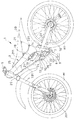
以下、図面を参照して本発明の一実施形態を説明する。図1は、本発明の一実施形態に係る変速機付き自転車の側面図である。自転車1の車体フレーム2は、ヘッドパイプ20およびヘッドパイプ20から斜め下後方に、左右二股に延びるメインフレーム21と、メインフレーム21の後部に設けられる揺動軸22で上下に揺動自在に支持されるスイングアーム23とからなる。メインフレーム21の下方には、補強パイプ24が設けられ、この補強パイプ24とメインフレーム21との間はブラケット25、26で結合される。前記スイングアーム23は二股状のスイングアームとすることができる。
【0017】
スイングアーム23の後端には後輪WRが支持される。ヘッドパイプ20には自転車1を操向可能なようにフロントフォーク4が枢支される。フロントフォーク4はアウタチューブとインナチューブとの組み合わせからなり、かつアウタチューブがインナチューブの上方に位置する倒立タイプである。フロントフォーク4の上部には、操向ハンドル5が設けられ、下部には前輪WFが支持される。
【0018】
メインフレーム21の下端には車体幅方向に延びるクランク軸7が設けられ、クランク軸7には、クランク8を介してペダル9が取り付けられる。クランク8およびペダル9はクランク軸7に対して左右一対設けられる。前記ブラケット26には変速機軸(シャフト)11および該シャフト11の周りに配置されたギヤの組立体(後述)を有する内装多段式の変速機10が設けられる。シャフト11はクランク軸7と平行にかつ揺動軸22に近接して配置される。
【0019】
クランク軸7には原動スプロケット12が設けられ、変速機10には入力スプロケット13と出力スプロケット14とが設けられる。また、後輪WRには後輪スプロケット(図示せず)が設けられる。クランク軸7のスプロケット12と変速機10の入力スプロケット13とはチェーン15で連結され、変速機10の出力スプロケット14と後輪スプロケットとはチェーン16で連結される。
【0020】
スイングアーム23にはブラケット231が設けられ、メインフレーム21にはブラケット211が設けられ、これらブラケット231および211間には、スイングアーム23が上方に回動されるときの衝撃を緩和するクッション装置18が設けられる。クッション装置18にはリザーバタンク19から作動流体が供給される。
【0021】
メインフレーム21にはリヤフェンダ30が取り付けられ、リヤフェンダ30とメインフレーム21とにまたがってサドル31が装着される。リヤフェンダ30は炭素繊維等、軽量素材で形成できる。前輪WFおよび後輪WRにはそれぞれディスクブレーキ32F,32Rが設けられる。また、操向ハンドル5に設けられる図示しない変速レバーから延びる変速機操作ケーブル101が前記補強パイプ24に沿って変速機10に延びている。
【0022】
図2は、クランク軸7およびシャフト11を含む位置における自転車1の要部断面図である。同図において、原動スプロケット12が固定されるクランク軸7は軸受34,35によりメインフレーム21に対して回転自在に取り付けられる。一方、変速機10のシャフト11は両端に形成されるねじに螺着されるナット36,37によってブラケット26、26に固定される。変速機10はシャフト11に対して回転自在な入力駆動体102を有し、この入力駆動体102に入力スプロケット13が結合される。
【0023】
さらに、シャフト11にはハウジング103が回動自在に設けられ、前記入力駆動体102の回転は変速ギヤ部(後述)を介して変速され、ハウジング103に伝達される。ハウジング103には出力スプロケット14が固定される。変速ギヤ部には、シャフト11に対してギヤを係合させるワンウェイクラッチ(後述)が複数設けられ、このワンウェイクラッチを各変速段毎に作動または非作動状態に切り換える。ワンウェイクラッチを切り換える操作カム104が設けられる。操作カム104は円筒状でシャフト11と同軸に該シャフト11の外周に沿って設けられる。
【0024】
操作カム104は、前記操作ケーブル101の操作によってシャフト11に対して各変速段毎に設定された予定の位置に回動させられる。そして、各変速段に対応する位置において、複数のワンウェイクラッチのうち予定のものの係止部材(爪)が、該ワンウェイクラッチに対応するギヤとシャフト11とに係合される。
【0025】
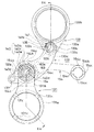
図3は、ワンウェイクラッチの操作カム104の展開図であり、円周の1/3つまり中心角120°の部分を示す。操作カム104には、ワンウェイクラッチの爪が貫通できる貫通孔104aが形成される。ワンウェイクラッチの爪はその保持器に対して回動するように構成され、この爪の一端が貫通孔104aを貫通してシャフト11に係合すると、爪の他端は変速用のギヤに形成される溝に係合される。したがって、各変速段に対応して貫通孔104aの位置を設定しておくことにより、各変速段毎に予定の変速ギヤをシャフト11に係合させることができる。
【0026】
図3において、円筒状操作カム104に変速段(1速〜7速)とワンウェイクラッチの番号を付して示したように、各変速段毎に、作動するワンウェイクラッチ、つまりシャフト11と変速ギヤとの双方に係合し得るワンウェイクラッチが設定される。例えば、第1速では、シャフト11と予定の変速ギヤとを係合させるワンウェイクラッチのうち第1のもののみが作動し得る状態(以下、「オン」という)になっていて、他のワンウェイクラッチが作動し得ない状態(以下「オフ」という)になっている。
【0027】
第2速では第1および第2のワンウェイクラッチがオン、第3速では第1と第3のワンウェイクラッチがオンである。また、第4速では、第1,第2と第4のワンウェイクラッチがオンであり、第5速では第1〜第3のワンウェイクラッチがオンである。さらに、第6速では、第4のワンウェイクラッチがオンであり、第7速では第3のワンウェイクラッチがオンである。
【0028】
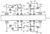
次に、上記操作カム104による変速ギヤの切り換えを図4を参照して説明する。この図において、シャフト11には、それぞれ第1のワンウェイクラッチ40を介して第1の太陽歯車(サンギヤ)50が、第2のワンウェイクラッチ41を介して第2のサンギヤ51が、第3のワンウェイクラッチ42を介して第3のサンギヤ52が、第4のワンウェイクラッチ43を介して第4のサンギヤ53設けられる。
【0029】
サンギヤ50には遊星ギヤ(キャリヤ)54が噛み合わされ、サンギヤ51にはキャリヤ55が噛み合わされる。キャリヤ54とキャリヤ55とは一体であり、小径のキャリヤ54には内歯車(リングギヤ)58が噛み合わされる。
【0030】
入力スプロケット13が外周に固定される入力駆動体102は、一対の軸受38によってシャフト11に支持される。前記リングギヤ58はワンウェイクラッチ44を介して入力駆動体102に連結される。
【0031】
サンギヤ52にはキャリヤ56が噛み合わされ、サンギヤ53にはキャリヤ57が噛み合わされる。キャリヤ56とキャリヤ57とは一体であり、小径のキャリヤ56にはリングギヤ59が噛み合わされる。キャリヤ54,55はキャリヤプレート27で枢支され、キャリヤ56,57はキャリヤプレート28で枢支される。これらキャリヤプレート27,28は互いに係合し、シャフト11を中心に、つまりサンギヤ50,51,52,53の周囲に一体で回転できるように設けられる。
【0032】
さらに、キャリアプレート27はワンウェイクラッチ45を介して入力駆動体102に連結されるとともに、キャリアプレート28はワンウェイクラッチ46を介してハウジング103に連結される。さらに、ハウジング103は、キャリア56に噛み合わされるリングギヤ59にワンウェイクラッチ47を介して連結される。また、ハウジング103の外周には出力スプロケット14が固定されるとともに、該ハウジング103は軸受38でシャフト11支持される。
【0033】
上記構成において、各変速段毎の動力(踏力)の伝達動作を図4に従って説明する。第1速では、ワンウェイクラッチ40がオンで、ワンウェイクラッチ41〜43がオフである。動力は、入力スプロケット13から入力駆動体102を介して入力され、ワンウェイクラッチ44を介してリングギヤ58に伝達される。さらにリングギヤ58の回転はキャリア54に伝達される。また、動力は、入力駆動体102からワンウェイクラッチ45を介してキャリアプレート27に伝達される。
【0034】
キャリヤ54はリングギヤ58の歯数Z58およびサンギヤ50の歯数Z50に従って、算出式{Z58/(Z58+Z50)}で計算される回転数でシャフト11の周囲を周回し、この周回はキャリアプレート27および28に伝達される。キャリアプレート28の周回運動はワンウェイクラッチ46を介してさらにハウジング103に伝達され、結果的に出力スプロケット14の回転に変換される。
【0035】
第2速では、ワンウェイクラッチ40,41がオンで、ワンウェイクラッチ42,43がオフである。この第2速では、入力駆動体102に入力された動力が、第1速と同一経路で出力スプロケット14に伝達される。しかし、ワンウェイクラッチ40,41がオンになっているので、キャリアプレート27の周回回転数はキャリア54(歯数Z54)およびキャリア55(歯数Z55)に噛み合うサンギヤ51(歯数Z51)、ならびにリングギヤ58(歯数Z58)の組み合わせから、算出式{(Z58・Z55)/((Z54・Z51)+(Z58・Z55))}で算出され、第1速より減速比は小さい。なお、第2速ではワンウェイクラッチ40,41がオンになっているが高速側に接続されるワンウェイクラッチ41のみが実質的にはオン状態として作用する。
【0036】
第3速では、ワンウェイクラッチ40,42がオンで、ワンウェイクラッチ41,43がオフである。第3速ではキャリアプレート27に第1速と同じ減速比で入力駆動体102の回転が伝達される。しかし、この第3速ではワンウェイクラッチ42がオンになっているのでキャリアプレート28の周回は、ワンウェイクラッチ46を介してではなく、キャリア56およびリングギヤ59の回転を通じてワンウェイクラッチ47からハウジング103に伝達される。すなわち、キャリアプレート28の周回は、リングギヤ59(歯数Z59)およびサンギヤ52(歯数Z52)の組み合わせから、算出式{(Z59+Z52)/Z59}に従って増速されてリングギヤ59に伝達され、出力スプロケット14に出力される。
【0037】
第4速では、ワンウェイクラッチ40,41,43がオンで、ワンウェイクラッチ42がオフである。第4速ではキャリアプレート27に第2速と同じ減速比で入力駆動体102の回転が伝達される。しかし、この第4速ではワンウェイクラッチ43がオンになっているのでキャリアプレート28の周回は、ワンウェイクラッチ46を介してではなく、キャリア57、56およびリングギヤ59の回転を通じてワンウェイクラッチ47からハウジング103に伝達される。すなわち、キャリアプレート28の周回は、リングギヤ59(歯数Z59)、キャリア56(歯数Z56)、キャリア57(歯数Z57)およびサンギヤ53(歯数Z53)の組み合わせから、算出式{1+((Z56・Z53)/(Z59・Z57))}に従って増速されてリングギヤ59に伝達され、出力スプロケット14に出力される。
【0038】
第5速では、ワンウェイクラッチ40,41,42がオンで、ワンウェイクラッチ43がオフである。したがって、第5速ではキャリアプレート27に第2速と同じ減速比で入力駆動体102の回転が伝達される。そして、第3速と同様、キャリアプレート28の周回は、キャリア56およびリングギヤ59の回転を通じてワンウェイクラッチ47からハウジング103に伝達される。すなわち、第2速と同じ減速比に基づくキャリアプレート28の周回は、リングギヤ59(歯数Z59)およびサンギヤ52(歯数Z52)の組み合わせから、算出式{(Z59+Z52)/Z59}に従って増速されてリングギヤ59に伝達され、出力スプロケット14に出力される。
【0039】
第6速では、ワンウェイクラッチ43がオンで、ワンウェイクラッチ40〜42がオフである。第6速では、サンギヤ50,51はいずれも自由に回転できるので、キャリア54,55は空転する。したがって、入力駆動体102の回転はワンウェイクラッチ44ではなく、ワンウェイクラッチ45からキャリアプレート27に伝達される。すなわち、入力回転数は減速されることなくキャリアプレート28に伝達され、それからキャリア56、リングギヤ59を介して増速されてハウジング103に伝達される。
【0040】
第7速では、ワンウェイクラッチ42がオンで、ワンウェイクラッチ40,41,43がオフである。第7速でも第6速と同様、サンギヤ50,51はいずれも自由に回転できるので、キャリア54,55は空転する。したがって、入力駆動体102の回転はワンウェイクラッチ44ではなく、ワンウェイクラッチ45からキャリアプレート27に伝達される。すなわち、入力回転数は減速されることなくキャリアプレート28に伝達され、それからキャリア56、リングギヤ59を介して増速されてハウジング103に伝達される。但し、サンギヤ52とキャリア56との組み合わせにより、第6速よりさらに増速される。
【0041】
上述の実施形態では、クランク軸7の回転をチェーン15で変速機10の入力スプロケット13に伝達したが、この伝達機構は次のように変形し得る。すなわち、クランク軸7に駆動ギヤを設けるとともに、前記変速機10の入力駆動体102にスプロケット103に代えて従動ギヤを固定し、これら双方のギヤを直接またはレイアウトの必要によってはアイドルギヤを介する等して連結することによってクランク軸7から変速機10へ回転を伝達できる。
【0042】
図5は、ギヤによる動力伝達機構を適用した変速機付き自転車の要部側面図であり、図1と同符号は同一または同等部分を示す。同図において、メインフレーム21と補強パイプ24とは連結部材39によって下部で連結され、この連結部材39とメインフレーム21に設けられるブラケット90とによって踏力伝達装置91が支持される。踏力伝達装置91はクランク軸7の回転を変速機10に伝達するギヤ列(後述)と、変速機10の出力を後輪WRに伝達する駆動スプロケットと、変速機10の出力を出力スプロケット92に伝達するギヤ列(後述)とからなる。
【0043】
図6は、クランク軸7、変速機10のシャフト、および出力スプロケット92を含む位置における自転車1の要部断面図であり、図2と同符号は同一または同等部分である。同図において、踏力伝達装置91に含まれるクランク軸7には、原動ギヤ93が固定され、この原動ギヤ93は変速機10の入力駆動体102に固定される入力ギヤ94に噛み合わされる。伝達装置91のケース911には軸受95,96によって出力軸97が支持され、この出力軸97には出力ギヤ48が固定される。変速機10のハウジング103には、中間ギヤ49が固定され、中間ギヤ49は出力ギヤ48と噛み合わされる。出力軸97はケース911から外方に突出されており、この突出端には出力スプロケット92が固定される。
【0044】
この構成により、クランク軸7から入力される踏力は原動ギヤ93および入力ギヤ94に伝達される。入力ギヤ94の回転は変速機10で変速され、中間ギヤ49を介して出力ギヤ48に伝達される。出力ギヤ48が回転すると、このギヤを支持する出力軸97および出力スプロケット92が回転し、出力スプロケット92に掛けられるチェーン16を介して後輪WRに動力が伝達される。
【0045】
図7は、本発明を適用した変速機付き自転車の他の実施形態の側面図であり、前記と同一の符号は同一または同等部分を表している。
【0046】
車体フレームは、下端部で前輪WFを軸支する左右1対のフロントフォーク4を操舵可能に支持するヘッドパイプ20と、ヘッドパイプ20から後方斜め下方に延びる左右1対のメインフレーム21と、両メインフレーム21の前端部下方から後方斜め下方に延びるダウンチューブ3と、各メインフレーム21の中央部から延びてサドル31を支持するサドルフレーム6とを備える。
【0047】
両メインフレーム21の後部に取り付けられた揺動軸22には、後端部で後輪WRを回転可能に支持する左右1対のスイングアーム23の前端部が揺動可能に支持される。スイングアーム23は、サスペンション18を介してメインフレーム21の中央部に連結され、揺動軸22を中心に上下方向に揺動可能である。両メインフレーム21の後部およびダウンチューブ3の後部の間には無段変速装置29が配置される。
【0048】
図8を併せて参照すると、無段変速装置29のケース61内に収納された変速機軸17は、ケース61外に突出した右端部が駆動スプロケット33と結合され、この駆動スプロケット33と後輪WRの被動スプロケット60(図16参照)との間にチェーン16が掛け渡される。無段変速装置29は、揺動軸22および後輪軸64の各中心軸線を含む仮想平面Hの近傍に変速機軸17が位置するように、車体フレームに対して配置される。
【0049】
クランク軸7に入力されたトルクは、無段変速装置29の変速機軸17、駆動スプロケット33、チェーン16および被動スプロケット60を介して駆動輪である後輪WRに伝達され、これを回転駆動させる。
【0050】
図8,図9を参照して無段変速装置29について説明する。ボルトにより結合される左右1対のケース部分61a,61bから構成されるケース61に、クランク軸7の両端部寄りの部分、アイドル軸62の両端部および変速機軸17の左端部と右端部寄りの部分が、左右1対の軸受120a,120b;120c,120d;120e,120fを介して回転可能に支持される。クランク軸7には、右軸受120b側から順に第1駆動ギヤ122および第2被動ギヤ124が設けられる。第1駆動ギヤ122は、クランク軸7が正転方向A0(自転車を前進させる方向。以下、クランク軸7が正転するときの各軸およびスプロケットの回転方向を符号A0で示す)のトルクのみを第1駆動ギヤ122に伝達する一方向クラッチ128を介してクランク軸7に駆動連結される。一方向クラッチ128は、図示しないキー部材によりクランク軸7に結合される。第2被動ギヤ124は、軸受129を介してクランク軸7に回転可能に支持される。
【0051】
アイドル軸62には、第1駆動ギヤ122と噛合する第1被動ギヤ123、および第2被動ギヤ124と噛合する第2駆動ギヤ125が設けられる。第2被動ギヤ124には、第3駆動ギヤ126が隣接して一体に固定され、該第3駆動ギヤ126は、入力軸63にスプライン結合された第3被動ギヤ127と噛合する。入力軸63は、その両端を両ケース部分61a,61bに対して軸受130a,130bにより回転可能に支持される。
【0052】
各駆動ギヤ122,125,126は、それに噛合する被動ギヤ123,124,127よりも大径なので、相互に噛合する駆動ギヤ122,125,126および被動ギヤ123,124,127により3つの増速段が構成される。それゆえ、3つの増速段を有する増速機構M1を介してクランク軸7により回転駆動される入力軸63は、クランク軸7の回転速度よりも増速された回転速度、本実施形態では約11倍に増速された回転速度で回転する。
【0053】
第3駆動ギヤ126および第3被動ギヤ127は、図10に示したように、非円形ギヤから構成され、入力軸63に不等速回転運動を行わせるための不等速回転伝達機構M2を構成する。具体的には、第3被動ギヤ127は、本実施形態において無段変速装置29に設けられる後述するリンクユニットU1〜U4の数と等しい数の山部127aおよび谷部127b、本実施形態ではそれぞれ4つの山部127aおよび谷部127bを有するギヤである。第3駆動ギヤ126は、第3被動ギヤ127の山部127aおよび谷部127bのそれぞれの数の整数倍、本実施形態では4倍の16の山部126aおよび谷部126bを有するギヤである。
【0054】
そして、第3駆動ギヤ126の谷部126bと第3被動ギヤ127の山部127aとが噛合するタイミングおよび第3駆動ギヤ126の山部126aと第3被動ギヤ127の谷部127bとが噛合するタイミングは、後述するように、脈動する変速機軸17の回転速度が最大となるタイミングおよび最小となるタイミングにそれぞれ合うように設定される。すなわち、クランク軸7と入力軸63とは、増速機構M1に組み込まれて変速機軸17の回転速度の脈動を低減するための不等速回転伝達機構M2を介して駆動連結される。
【0055】
図8,図9を参照し、入力軸63は、変速機構M3を構成する複数の、本実施形態では4つのリンクユニットU1〜U4を介して変速機軸17に連結される。変速機構M3は、運転者が変速操作部材としての変速レバー(図示せず)を操作することにより動作する変速操作機構M4により操作され、クランク軸7の回転速度に対する変速機軸17の回転速度の比である変速比を無段階に変更する。
【0056】
さらに図11,図12を併せて参照すると、各リンクユニットU1〜U4は、入力軸63に偏心して枢着された駆動リンク131と、変速機軸17に一方向クラッチ136を介して連結された揺動体133と、第1枢支部を構成する第1枢軸134で駆動リンク131に枢着されると共に第2枢支部を構成する第2枢軸135で揺動体133に枢着された伝達リンク132とを備える。
【0057】
駆動リンク131は、円環状の第1結合部131aと、第1結合部131aに連なると共に1対のプレート部131b1を有する二股状の第2結合部131bとから構成される。伝達リンク132は、その一端部132aをリベット137により所定の間隔を保って連結された1対のプレー卜132cから構成される。揺動体133は、伝達リンク132の両プレート132cの間に挟まれて配置される第1結合部133aと、第1結合部133aに連なる円環状の第2結合部133bとから構成される。
【0058】
駆動リンク131は、その第1結合部131aが、入力軸63とスプライン結合されて一体に回転する偏心リング138の外周にすべり軸受139を介して回転可能に支持されることにより、入力軸63に対して偏心して枢着される。偏心リング138の回転軸線、すなわち駆動リンク131の中心軸線は、入力軸63の回転軸線に対して所定量だけ偏心している。第1結合部131aには、図11,図12に示したように、周方向に等間隔で複数の、例えば4つの油溝131cが径方向に延びて形成され、ケース61内の潤滑油が油溝131cを通じてすべり軸受139に供給される。
【0059】
第2結合部131bの両プレート部131b1に固定されて支持される第1枢軸134に、両プレート部131b1の間に配置されたニードル軸受140を介して、伝達リンク132が回動可能に支持される。ニードル軸受140は、第1枢軸134の外周に嵌合される内輪140aと、内輪140aの径方向外方に配置されて両プレート132cの一端部132aに形成された孔にインローにて結合される外輪140bと、内輪40aと外輪40bとの間に配置される多数の二ードル140cとから構成される。
【0060】
ニードル140cの軸線方向への移動は、ニードル軸受140の両端側に配置された1対のスラストワッシャ143により規制され、隙間無くニードル140cをつめるのでリテーナは不要である。外輪40bには、周方向に間隔をおいて複数、本実施形態では周方向に等間隔に4つの油孔140dが形成される。
【0061】
伝達リンク132は、揺動体133の第1結合部133aが第2枢軸135により、ニードル軸受141からなる軸受を介して回動可能に支持されることで揺動体133に枢着される。ニードル軸受141は、第2枢軸135の外周に配置されて揺動体133の第1結合部133aに囲まれて保持される多数のニードル141aから構成される。ニードル141aの軸線方向での移動は、ニードル141aの両端側に配置された1対のスラストワッシャ144により規制され、隙間無くニードル140cをつめるので、ニードル軸受141は、前記ニードル軸受140と同様にリテーナを有していない。第1結合部133aの両側面には、図12に示したように、周方向に間隔をおいて複数の、例えば3つの油溝133cが径方向に延びて形成されている。ケース61内の潤滑油は、油溝133cを通じてニードル軸受141に供給される。
【0062】
揺動体133は、第2結合部133bにおいて、変速機軸17を正転方向A0に回転させるトルクのみを伝達する一方向クラッチ136を介して変速機軸17に連結される。したがって、一方向クラッチ136は、揺動体133が変速機軸17の正転方向A0での角速度ω(図21参照)、すなわち回転速度よりも大きな角速度で正転方向A0に揺動するときにのみ、揺動体133から変速機軸17にトルクを伝達する。
【0063】
図8に示したように、4つのリンクユニットU1〜U4は、入力軸63および変速機軸17に対して軸線方向(車幅方向でもある。)に等間隔で配列される。具体的には、入力軸63には、隣接するリンクユニットU2,U3;U3,U4の間隔を保持する2つの円環状のカラー146が駆動リンク131の第1結合部131の側方で嵌合される。入力軸63の右端部近傍で隣接するリンクユニットU1,U2の間隔は、両リンクユニットU1,U2の間に配置された第3被動ギヤ127により保持される。
【0064】
このように、本実施形態の無段変速装置29では、アイドル軸62の車幅方向での長さを極力短くすると共に、クランク軸7に装着される第2被動ギヤ124および第3駆動ギヤ126の軽量小型化のために、第3駆動ギヤ126と噛合する第3被動ギヤ127が、右端のリンクユニットU1およびそれに隣接するリンクユニットU2の間で入力軸63に装着される。
【0065】
さらに、図8,図9を参照すると、右端のリンクユニットU1の駆動リンク131が、車幅方向で第1駆動ギヤ122と第3駆動ギヤ126との間に配置され、しかもその往復運動により、クランク軸7の径方向で第1駆動ギヤ122および第3駆動ギヤ126と重なり得る位置に配置される。
【0066】
一方、変速機軸17には、隣接するリンクユニットU1,U2;U2,U3;U3,U4の間隔を保持する部材であるスペーサとしての3つの円環状のカラーが、揺動体133の第2結合部133bの側方で嵌合される。
【0067】
そして、図13に示したように、4つのリンクユニットU1〜U4の駆動リンク131は、異なる位相で入力軸63に枢着されており、本実施形態では、全ての駆動リンク131の回転軸線が入力軸63の周方向に90°の等角度で分布するように入力軸63に枢着される。なお、図13には、後述する変速リンク154が最小変速比位置を占めているときの第3枢軸153、支持軸159、第4枢軸161および中間リンク162が示されている。
【0068】
なお、図8に示したように、各リンクユニットU1〜U4において、偏心リング138およびすべり軸受139の軸線方向での両端部側は、入力軸63にスプライン結合される1対の円板状の被覆プレート149により覆われる。そして、被覆プレート149は、カラー146,148および第3被動ギヤ127により、入力軸63上での軸線方向の移動が阻止される。
【0069】
図8,図9,図14を参照すると、両ケース部分61a,61bに軸受150を介して回動可能に支持される支持部材151と、第1枢軸134で各リンクユニットU1〜U4に枢着されると共に第3枢支部を構成する第3枢軸153で支持部材151に枢着される変速リンク154とを備える。
【0070】
変速操作機構M4はさらに、前記変速レバーに接続される操作ワイヤ155の端部が係止されたドラム156と、このドラム156と一体に回動する操作軸157と、操作軸157にダボにより連結される支持軸159と、支持軸159と一体に回動するレバー160と、第3枢軸153で支持部材151に枢着されると共に第4枢支部を構成する第4枢軸レバー160に枢着される中間リンク162とを備える。
【0071】
図8,図9,図11,図12を参照すると、変速リンク154は、その円環状の先端部154aを、ニードル軸受140の外周において伝達リンク132の両プレート132cの間で挟まれて配置されたニードル軸受163を介して回動可能に支持されることにより、第1枢軸134で枢着される。ニードル軸受163は、外輪140bの外周に配置されて先端部154aにより囲まれて保持される多数のニードル163aから構成される。それゆえ、駆動リンク131の両プレート部131b1の間には、第1枢軸134に対して径方向に直列に配置された二段のニードル軸受140,163が配置される。ニードル163aの軸線方向での移動は、ニードル163aの両端側に配置された1対のスラストワッシャ164により規制され、隙間無くニードルをつめるので、ニードル軸受163は、ニードル軸受140と同様にリテーナを有していない。
【0072】
図11,図12に示したように、先端部154aの両側面にはそれぞれ、周方向に間隔をおいて複数、本実施形態では周方向に等間隔に4つの油溝154cが設けられる。ケース61内に充填された潤滑油は、油溝154cを通ってニードル軸受163に供給され、さらに外輪140bの油孔140dを通ってニードル軸受140に供給される。なお、図9に示したように、右ケース部分61bには,ブリーザ管165およびケース61内の潤滑油を排出するためのドレインボルト166が設けられる。
【0073】
図8,図9,図14を参照すると、支持部材151は、U字形状に屈曲されて形成された板材からなる支持リンク151aと、支持リンク151aの両端部に結合されて車幅方向での間隔を保持するスペーサとしての連結軸151bとを備える。支持リンク151aは、車幅方向で対面する互いに平行な1対の側部151a1と、両側部151a1に連なる連結部151a2とから構成される。支持部材151は、各ケース部分61a,61bに保持された軸受150に支持された中心軸152が固着されるので、ケース61に回動自在に支持される。さらに、支持リンク151aの一方の側部である右側の側部151a1には、右ケース部分61bの内面に突出して形成された第1,第2ストッパ167,168(図9参照)にそれぞれ当接する1対の当接面151a3,151a4がそれぞれ形成される。第1,第2ストッパ167,168は、変速リンク154の最小変速比位置および最大変速比位置をそれぞれ規定する。
【0074】
図14を参照すると、支持部材151の両側部151a1には、その連結部151a2付近に両側部151aに渡って第3枢軸153が固定されて支持される。その先端部154aにて4つのリンクユニットU1〜U4にそれぞれ枢着される4つの変速リンク154は、その円環状の基端部154bにて、多数のニードル169aを有するニードル軸受169を介して第3枢軸153で枢着されることにより、支持部材151に枢着される。基端部154bの両側面には、それぞれ、周方向に間隔をおいて複数、本実施形態では周方向に等間隔に4つの油溝154cが設けられる。ケース61内に充填された潤滑油は、油溝154cを通ってニードル軸受169に供給される。
【0075】
変速リンク154は、第3枢軸153に軸線方向(車幅方向)に等間隔で配列され、そのためにカラー170および中間リンク162が使用される。すなわち、中央で互いに隣接する変速リンク154(これら変速リンク154はリンクユニットU2,U3に枢着される。)の間にはスペーサとしてのカラー170が配置される。そして、両端部の変速リンク154(この変速リンク154はリンクユニットU1,U4にそれぞれ枢着される。)とそれに隣接する変速リンク154との間には、二股に分岐した中間リンク162の両先端部162aがそれぞれすべり軸受171を介して第3枢軸153に回動可能に支持される。それゆえ、支持部材151の両側部151a1の間に配置される両先端部162aが、カラー170と同様の機能を有するスペーサとして利用される。
【0076】
図14,図15を参照すると、支持軸159は、その一端を左ケース部分61aに軸受172を介して回動可能に支持される。支持軸159の他端は、各リンクユニットU1〜U4の駆動リンク131に作用する入力軸163からの駆動力の分力(図20参照)が、第1枢軸134、変速リンク154、支持部材151、第3枢軸153、中間リンク162、レバー160および支持軸159を通じてドラム156を回動させることを阻止するための二方向クラッチ158を介して、右ケース部分61bに保持される。
【0077】
一方向クラッチ158は、右ケース部分61bに固定されたアウタレース158aと、支持軸159と一体に回転するインナレース158bと、両レース158a,158bの径方向での間の収容空間に配置された偶数、本実施形態では8つのローラ158cと、1対のローラ158cの周方向での間で前記収容空間に配置された圧縮スプリングからなるクラッチスプリング158dと、クラッチスプリング158dとは反対側で2つのローラ158cの周方向での間に配置されたリテーナ158eとから構成される。
【0078】
操作軸157に一体形成されたリテーナ158eは、操作軸157がシフトアップをするための回動方向A2(以下、アップ方向A2)およびシフトダウンをするための回動方向A3(以下、ダウン方向A3)へ回動したときにローラ158cと当接する。リテーナ158eは、操作軸157の直径方向で対向してインナレース158bに形成された凹部158b1からなる係合部と係合可能な突部158e3からなる係合部を有する1対の第1保持部158e1と、周方向で両第1保持部158e1の間に位置する第2保持部158e2とを有する。
【0079】
凹部158b1と突部158e3との間には、リテーナ158eとインナレース158bとの相対回動を可能とするための間隙158fが形成される。そして、凹部158b1と突部158e3とが係合するまでの相対回動により、第1,第2保持部158e1,158e2が、クラッチスプリング158dの弾発力に抗してローラ158cを押圧し、ローラ158cを、アウタレース158aとインナレース158bの間に食い込むこと(すなわちロックすること)ことがない状態、すなわちロック解除状態にする。
【0080】
インナレース158bの外周にはカム面158b2が形成される。このカム面158b2は、クラッチスプリング158dを介して互いに対向する1対のローラ158cのうち、アップ方向A2側のローラ158c1は、アップ方向A2への支持軸159の回動を許容する一方でダウン方向A3への支持軸159の回動を阻止する。ダウン方向A3側のローラ158c2は、ダウン方向A3への支持軸159の回動を許容する一方で、アップ方向A2への支持軸159の回動を阻止するように、前記収容空間の径方向での幅を周方向で異ならせるように形成される。
【0081】
それゆえ、前記変速レバーに加えられた操作力が操作ワイヤ155を介してドラム156をアップ方向A2に回動させると、図15に二点鎖線で示したように、第1,第2保持部158e1,158e2がアップ方向A2に相対回動し、ローラ158c2に当接して該ローラ158c2をロック解除状態にした後、突部158e3と凹部158b1とが係合することで第1保持部158e1がインナレース158bに係合して、支持軸159と一緒にアップ方向A2に回動する。
【0082】
これとは逆に、操作力が操作ワイヤ155を介してドラム156をダウン方向A3に回動させると、第1,第2保持部158e1,158e2がダウン方向A3に相対回動してローラ158c1に当接して該ローラ158c1をロック解除状態にした後、突部158c3と凹部158b1とが係合することで第1保持部158e1が、インナレース158bに係合し、支持軸159と一緒にダウン方向A3に回動する。
【0083】
ところで、図9を参照すると、クランク軸7の回転中、揺動体133および一方向クラッチ136を介して変速機軸17にトルクを伝達し、変速機軸17を回転駆動しているリンクユニットU1〜U4についてみると、リンクユニットU1〜U4の駆動リンク131を往復運動させる入力軸63からの駆動力は、伝達リンク132を介して揺動体133に作用する一方、変速リンク154を介して第3枢軸153の方向に作用する。
【0084】
この第3枢軸153に作用する駆動力の分力Fにより、リンクを介して支持軸159に発生するトルクTは、図20に示したように、変速機軸17を回転駆動してしいるリンクユニットU1〜U4の駆動リンク131に作用する駆動力の変化に対応する大きさおよび向きを有しており、第4リンクおよびレバー160を介して支持軸159を回動させようとする。なお、図20において、符号U1〜U4は変速機軸17を回転駆動しているリンクユニットを示し、符号F0は、該分力Fの大きさ目安を示すための値を示している。
【0085】
このとき、操作ワイヤ155を通じて操作力がリテーナ158eに作用していなければ、トルクTがアップ方向A2およびダウン方向A3のいずれの方向に支持軸159を回動させようとしても、ローラ158cがロック状態になって支持軸159は回動しない。また、シフトアップ(シフトダウン。以下、括弧内には、シフトダウンに対応する説明を記す。)をさせる操作力がリテーナ158eに作用しているときに、トルクTが支持軸159をアップ方向A2(ダウン方向A3)に回動させるように作用すると、トルクTがアシスト力となって操作力が軽減される。一方、分力Fが支持軸159をダウン方向A3(アップ方向A2)に回動させるように作用するときには、ローラ158cがロック状態になって、支持軸159がダウン方向A3(アップ方向A2)に回動することが阻止される。
【0086】
それゆえ、操作軸157、二方向クラッチ158、支持軸159、レバー160、第4枢軸161および中間リンク162は、前記操作レバーによる操作力を第3枢軸153に伝達する伝達機構M5を構成する。
【0087】
図16,図17を参照して、リヤハブ80および被動スプロケット60に関連して説明する。後輪軸64に軸受81を介して回転可能に支持されるリヤハブ80の右端部には、一方向クラッチ82を介して被動スプロケット60が設けられる。そして、一方向クラッチ82の右端部は、被動スプロケット60と後輪軸64との間に設けられたカバー83により覆われる。
【0088】
一方向クラッチ82は、被動スプロケット60により構成されるアウタレース82aと、リヤハブ80にネジ結合されたインナレース82bと、両レース82a,82bの径方向での間の収容空間に配置された複数のローラ82cと、前記複数のローラ82cの周方向での間隔を保持するリテーナ82dと、アウタレース82aとリテーナ82dとの間に配置された圧縮スプリングからなるクラッチスプリング82eとから構成される。
【0089】
リテーナ82dは、車幅方向に離隔した円環状の大径リング82d1および小径リング82d2と、両リング82d1,82d2に連結されて車幅方向に延びて周方向で隣接するローラ82cの間に位置する保持部82d3と、直径方向で対向する位置にある1対の保持部82d3に一体形成されて被動スプロケット60に形成された長孔60aを右方に貫通して突出する突起82d4からなる位置決め部とを有する。突起82d4がカバー83に形成された凹部83aからなる係合部と係合することにより、カバー83とリテーナ82dとが一体に回転可能になる。
【0090】
クラッチスプリング82eは、直径方向で対向する位置にある1対の保持部82d3とアウタレース82aとの間に配置されて、該1対の保持部82d3を、その弾発力により正転方向A0に付勢している。
【0091】
カバー83は、後輪軸64に嵌合されて固定された車筒84に固定された線材からなる円環状のフリクションスプリング85の弾発力により径方向外方に付勢される。また、カバー83の外周とアウタレース82aとの間は、シール85により、カバー83の内周と車筒84との間は、シール86により、それぞれ密閉にされる。
【0092】
フリクションスプリング85のセット荷重は、遮断状態にある一方向クラッチ82が接続状態に移行するとき、クラッチスプリング82eが正転する被動スプロケット60により圧縮されて、ローラ82cがアウタレース82a(被動スプロケット60)の内周面に形成されたカム面82a1とインナレース82bとの間でロック状態になる(図17に二点鎖線で示される。)ように、後輪軸64とリテーナ82dとの間で相対回転が生じさせない摩擦力をカバー83とフリクションスプリング85との間に生じさせる大きさであって、しかも、一方向クラッチ82が接続状態になったとき、カバー83がリテーナ82d、被動スプロケット60(アウタレース82a)およびインナレース82bと共に回転することができるような大きさに設定される。
【0093】
このような一方向クラッチ82により、被動スプロケット60が正転方向A0に回転するとき、ローラ82cがロック状態になって、被動スプロケット60とリヤハブ80とが一体に回転する。また、自転車の走行中に運転者がペダル9を漕ぐことを止めたとき、もしくは運転者が降車した状態で、自転車を前進させるときは、クラッチスプリング82eの弾発力によりチェーンの弛み分だけ被動スプロケットが正転方向A0と逆の方向に回転し、ローラ82cがロック解除状態になって、一方向クラッチ82が遮断状態になり、被動スプロケット60が停止した状態で、後輪WRのみ、すなわちリヤハブ80のみが正転方向A0に回転する。さらに、例えば運転者が降車した状態で、自転車を後進させるときは、クラッチスプリング85の弾発力により、ローラ82cは図17に示したロック解除状態にあって、一方向クラッチ82が遮断状態になるため、被動スプロケット60が停止した状態で、後輪WR、すなわちリヤハブ80のみが逆転方向に回転する。
【0094】
つぎに、この無段変速装置29の動作について説明する。図9に示したように、無段変速装置29が最小変速比にある状態で自転車が走行しているとき、支持部材151が第1ストッパ167に当接した状態で第3枢軸153の位置が固定されている。このとき、入力軸63が1回転する間に、図18(A)で示したように、入力軸63からの駆動力により、入力軸63の1回転あたり各駆動リンク131は図示される両位置P1,P2の間で往復運動し、各リンクユニットU1〜U4は、順次、揺動角度範囲θ1で揺動体133を揺動させる。そして、各リンクユニットU1〜U4が一方向クラッチ136を介して変速機軸17に連結されていることから、4つのリンクユニットU1〜U4を有する無段変速装置29において、入力軸63の1回転の間に、変速機軸17は、図13(A)に示したように、4つのリンクユニットU1〜U4のうち、正転方向A0での最大角速度(回転速度)で変速機軸17を回転駆動するリンクユニットU1〜U4により順次回転駆動される。
【0095】
このとき、変速機軸17の回転速度が最大となるタイミングでは、第3駆動ギヤ26および第3被動ギヤ127からなる非円形ギヤを使用した不等速回転伝達機構M2により入力軸63の回転速度が最小となり、例えばリンクユニットU1が変速機軸17を駆動している状態から、リンクユニットU1に対して90°の位相を有するリンクユニットU2が変速機軸17を駆動する状態に移行するタイミング、すなわち変速機軸17の回転速度が最小となるタイミングでは、不等速回転伝達機構M2により、入力軸63の回転速度が最大となって、変速機軸17の回転速度の変動幅が減少して、その脈動が低減される。なお、図19において、符号U1〜U4は変速機軸17を回転駆動しているリンクユニットを示し、符号ω0は、変速機軸17の角速度ωの大きさ目安を示すための値を示している。
【0096】
この最小変速比での運転状態から、シフトアップするために運転者が前記変速レバーを操作すると、操作力が操作ワイヤ155、ドラム156および操作軸157を介して二方向クラッチ158(図15参照)のリテーナ158eをアップ方向A2に回動させる。このとき、図20(A)に示したように、各リンクユニットU1〜U4に対する入力軸63からの駆動力により変速機軸17が加速されるときの該駆動力の分力F(図20においてプラス側の分力)によりリンクを介して支持軸159に発生するトルクTが、アシスト力として変速リンク154、中間リンク162およびレバー160を介して支持軸159に作用する。そして、支持軸159の回動により、第3枢軸153が、支持部材151を支持する中心軸152を中心とする円形の変速軌道上を、図21に示される最大変速比での位置に向けて移動して、より大きな変速比で後輪WRが回転駆動される。
【0097】
図18(B)を参照すると、変速リンク154および第3枢軸153が最大変速比にある状態(図21参照)で、入力軸63が1回転する間に、入力軸63の1回転あたり各駆動リンク131は図示される両位置P3,P4の間で往復運動し、各リンクユニットU1〜U4は、最小変速比での揺動角度範囲θ1よりも大きい揺動角度範囲θ2で揺動体133を揺動させる。そして、4つのリンクユニットU1〜U4により、入力軸63の1回転の間に、変速機軸17は、図19(B)に示したように、正転方向A0での最大角速度(回転速度)で変速機軸17を回転駆動するリンクユニットU1〜U4により順次回転駆動される。このときも、前述の最小変速比のときと同様に、不等速回転伝達機構M2により、変速機軸17の回転速度の変動幅が減少して、その脈動が低減される。
【0098】
この最大速度比での運転状態から、シフトダウンするために運転者が前記操作レバーを操作することにより、操作力が操作ワイヤ155、ドラム156および操作軸157を介して一方向クラッチ158(図14参照)のリテーナ158eをダウン方向A3に回動させる。このとき、図20(B)に示したように、各リンクユニットU1〜U4に対する入力軸63からの駆動力により変速機軸17が減速される方向の該駆動力の分力F(図20においてマイナス側の分力)によりリンクを介して支持軸159に発生するトルクTが、アシスト力として支持軸159に作用する。そして、支持軸159の回動により、第3枢軸153が、最大変速比での位置から最小変速比での位置に向けて前記変速軌道上を移動して、より小さい変速比で後輪WRが回転駆動される。
【0099】
このようにして、変速操作機構M4での変速操作により、第3枢軸153が、最小変速比での位置と最大変速比での位置との間の任意の位置を無段階に占めることかできるので、クランク軸7の回転が無段階に変速されて後輪WRに伝達される。
【0100】
次に、前述のように構成された実施形態の作用および効果について説明する。クランク軸7により回転駆動される入力軸63と変速機軸17を駆動連結する変速機機構M3は、ギヤを使用しない複数のリンクユニットU1〜U4から構成されるので、前記従来技術とは異なり、騒音の発生が抑制され、変速機構M3が計量化される。また、入力軸63と変速機軸17とが複数のリンクから構成されるリンクユニットU1〜U4を介して駆動連結されるので、クランク軸7、ひいては車体フレームに対する変速機軸17の配置の自由度が大きくなる。そのため、後輪WRが上下方向に揺動可能なスイングアーム23により支持される場合にも、車体フレームに対して揺動軸22を含む仮想平面Hの近傍に変速機軸17を配置することかできる。
【0101】
クランク軸7と入力軸63との間に増速機構M1が設けられることにより、変速機軸17の回転速度の脈動の周期が短縮されるので、重量増および大型化を抑制しつつ、運転者が回転速度の脈動を感じることが少ない快適な走行性を実現することができる。
【0102】
また、クランク軸7と入力軸63との間に、非円形ギヤである第3駆動ギヤ126および第3被動ギヤ127から構成される不等速回転伝達機構M2が配置されて、各変速比において、変速機軸17の回転速度が最大となるタイミングで入力軸63の回転速度が最小となり、変速機軸17の回転速度が最小となるタイミングで入力軸63が回転速度が最大となるよう両ギヤ126,127を噛合させることにより、変速機軸17の回転速度の脈動を一層低減することができる。
【0103】
変速操作のための操作力を第3枢軸153に伝達する伝達機構M5により、変速リンク154を介して伝達される、リンクユニットU1〜U4を駆動する駆動力の分力Fが操作力のアシスト力とされるので、クランク軸7により入力軸63が回転駆動されて、その駆動力により駆動される駆動リンク131の往復運動を利用することにより、運転者がペダル9を漕いでクランク軸7を回転させているときの変速操作の操作力が軽減されて、軽快な変速操作が可能になる。
【0104】
しかも、伝達機構M5には、変速機構M3側から作用する力による支持軸159の回動を阻止し、前記操作レバーから作用する操作力による支持軸159の回動を許容する二方向クラッチ158が設けられるので、自転車の停止時はもちろん、走行中であっても確実に変速操作ができる。
【0105】
入力軸63に枢着される駆動リンク131の一つである右端のリンクユニットU1の駆動リンク131が、車幅方向で、増速機構M1の1対の増速段をそれぞれ構成するギヤである第1駆動ギヤ122と第3駆動ギヤ126との間に配置され、しかも第1駆動ギヤ122および第3駆動ギヤ126とクランク軸7の径方向で重なり得る位置に配置されることにより、車幅方向で無段変速装置29を小型化でき、さらにクランク軸7と入力軸63との軸間距離を小さくすることができて、この点でも無段変速装置29の小型化に寄与できる。
【0106】
また、増速機構M1の最終ギヤである第3被動ギヤ127は、両端がケース61に支持された入力軸63の一端部寄りに装着されることにより、第3駆動ギヤ126から第3被動ギヤ127を通じて入力軸63が受ける荷重による入力軸63のたわみを極力抑制することができると共に、第3被動ギヤ127を、入力軸63に等間隔に配列されるリンクユニットU1〜U4のスペーサとして利用できることにより、入力軸63の車幅方向での長さを抑制でき、無段変速装置29を車幅方向で小型化できる。
【0107】
駆動リンク131と伝達リンク132とを枢着し、各リンクユニットU1〜U4に変速リンク154を枢着するために、第1枢軸134に対して径方向に直列に二段のニードル軸受140,163が配置され、各ニードル軸受140,163がリテーナレスの軸受とされることにより、ニードル軸受140,163の摩擦が低減される。しかも、ニードル軸受140,163の第1枢軸134の軸線方向でのそれらリンク131,132,154の幅を減少させることができるので、変速機構M3、ひいては無段変速装置29を車幅方向で小型化できる。
【0108】
変速リンク154を回動自在に支持する第3枢軸153は、支持部材151の、対面する互いに平行な1対の側部151a1により支持される。しかも、各側部151a1がケース61に支持されることにより、伝達機構M5および第3枢軸153を通じてそれぞれの側部151a1に作用する変速操作のための操作力に基づく荷重が小さくなることと相まって、各側部151a1の変形や倒れが抑制され、しかも軽量化ができる。さらに、両側部151a1において第3枢軸153が支持される部分付近は、連結部151a2により連結されることにより、支持部材151の剛性が高められるので、側部151a1の変形や倒れが一層少なくなる。
【0109】
第3枢軸153に支持される全ての変速リンク154を車幅方向に等間隔に配列するために、カラー170のほかに第3枢軸153に支持される中間リンク162を利用して隣接する変速リンク154の間隔を保持していることにより、同様に、入力軸63に枢着される全てのリンクユニットU1〜V4を車幅方向に等間隔に配列するために、カラー146のほかに第3被動ギヤ127を利用して隣接するリンクユニットU1〜U4の間隔を保持していることにより、スペーサとしてのカラーの個数を削減できると共に、第3枢軸153を支持する支持部材151および入力軸63の車幅方向での幅を減少させて、支持部材151および入力軸63ひいては無段変速装置29を車幅方向で小型化できる。
【0110】
以下、前述した実施形態の一部の構成を変更した実施形態について、変更した構成に関して説明する。
前記実施形態では、不等速回転伝達機構M2は非円形ギヤから構成されたが、不等速回転伝達機構M2は、偏心ギヤ等の他の不等速回転を生じさせる部材で構成されてもよい。増速機構M1は、3を除く複数の増速段または1つの増速段を有するものであってもよい。さらに、自転車はダウンヒル用以外の自転車であってもよく、また、2輪車あるいは3輪車であってもよい。
【0111】
支持リンク151aは、前記実施形態では1対の側部151a1および連結部151a2を構成する単一の部材から構成されたが、1対の側部および連結部を別個の3つの部材として、それら部材を結合することにより構成することもできる。
【0112】
【発明の効果】
本発明によれば、以下のような高価が達成される。
(1)請求項1〜5の発明によれば、変速機軸を、クランク軸と同軸上に配置しないことにより、車体の形状に応じて変速機とクランク軸との位置を自由に設定することができる。
(2)請求項2の発明によれば、スイングアームの揺動軸に近接させて変速機軸を配置できる。したがって、クランク軸と同軸上に変速機軸が配置されるのと違い、揺動軸をクランク軸に近接しなくても、リヤディレーラを設けないで後輪に駆動力を伝達するチェーンの動揺を小さくすることができる。
(3)請求項3の発明によれば、変速機軸を揺動軸の後方に配置するよりも、スイングアームの揺動に伴う前記チェーンの動揺を小さくすることができる。
(4)請求項4の発明によれば、変速機やギヤ装置をケース内にコンパクトに収納することができる。
(5)請求項5の発明によれば、クランク軸と変速機との相対位置の選択の自由度を高められる。
(6)請求項6の発明によれば、クランク軸により回転駆動される入力軸と出力軸としての変速機軸とが、ギヤを使用しないリンクユニットを介して連結されるので、騒音の発生が抑制され、変速機構が軽量化される。
(7)請求項7の発明によれば、入力軸と変速機軸とが複数のリンク機構を介して連結されるので、クランク軸や変速機軸の配置自由度が大きくなる。
(8)請求項8の発明によれば、クランク軸と入力軸との間に増速機構が設けられるので、変速機軸の回転速度の脈動の周期が短縮されると共に、その変動幅が減少するので、重量増および大型化を抑制しつつ、簡単な構造により脈動が低減されて、運転者が回転速度の脈動を殆ど感じることがないような快適な走行性を実現することができる。
(9)請求項9の発明によれば、クランク軸と入力軸との間に不等速回転伝達機構が配置されるので、各変速比において、変速機軸の回転速度が最大となるタイミングで入力軸の回転速度が最小となり、変速機軸の回転速度が最小となるタイミングで入力軸が回転速度が最大となるように各ギヤを組み合わせれば、変速機軸の回転速度の脈動を一層低減することができる。
【図面の簡単な説明】
【図1】本発明の一実施形態に係る変速機付き自転車の側面図である。
【図2】踏力の伝達装置を示す自転車の要部断面図である。
【図3】ワンウェイクラッチ用操作カムの展開図である。
【図4】内装多段式変速機の構成を示す模式図である。
【図5】第2実施形態に係る自転車の要部側面図である。
【図6】第2実施形態に係る踏力伝達装置の要部断面図である。
【図7】本発明を適用した変速機付き自転車の他の実施形態の左側面図である。
【図8】図9のX1−X1線およびX2−X2線での断面図である。
【図9】最小変速比の状態にあるときの図7の無段変速装置について、右ケース部分を外し、各種の軸を断面としたときの右側面図である。
【図10】図7の無段変速装置の不等速回転伝達機構を構成するギヤの正面図である。
【図11】図12のX4−X4線での断面図である。
【図12】図7の無段変速装置の変速機構を構成するリンクユニットの右側面図である。
【図13】図7の無段変速装置の変速機構を構成する4つのリンクユニットの入力軸への枢着の形態を説明する模式図である。
【図14】図9のX3−X3線およびX5−X5線での断面図である。
【図15】図14のX6−X6線での断面図である。
【図16】図7の自転車のリヤハブおよび被動スプロケットについて、図17のX−X線での断面図である。
【図17】図16のX7−X7線での断面図である。
【図18】図7の無段変速装置の揺動体の揺動角度範囲を説明する模式図であり、(A)は最小変速比でのものであり、(B)は最大変速比でのものである。
【図19】図7の無段変速装置の変速機軸の角速度を説明する図であり、(A)は最小変速比でのものであり、(B)は最大変速比でのものである。
【図20】図7の無段変速装置の入力軸の1回転における駆動力の分力を説明する図であり、(A)は最小変速比でのものであり、(B)は最大変速比でのものである。
【図21】図9と同様の右側面図であり、無段変速装置が最小変速比の状態にあるときのものである。
【符号の説明】
1…自転車、2…車体フレーム、7…クランク軸、10…変速機、11…シャフト(変速機軸)、16…チェーン、17…変速機軸、21…メインフレーム、22…揺動軸、23…スイングアーム、29…無段変速装置、33…駆動スプロケット、61…ケース、63…入力軸、104…操作カム、M1…増速機構、M2…不等速回転伝達機構、M3…変速機構、M4…変速操作機構、U1〜U4…リンクユニット
[0001]
BACKGROUND OF THE INVENTION
The present invention relates to a bicycle with a transmission, and more particularly to a bicycle with a transmission suitable for increasing the degree of freedom in designing a body frame.
[0002]
[Prior art]
There is known a bicycle with a transmission provided with an internal transmission arranged coaxially with a crankshaft. For example, in a bicycle described in JP-A-6-48368, a motor is connected to a transmission switching lever arranged on a crankshaft, and the transmission is switched by this motor.
[0003]
[Problems to be solved by the invention]
The bicycle with a transmission has the following problems to be solved. First, since the output position of the transmission for transmitting the pedaling force to the rear wheels is limited to the crankshaft or in the immediate vicinity thereof, the degree of freedom in designing the vehicle body is small. For example, when a swing arm that supports a rear wheel is configured to be swingable with respect to a main frame of a vehicle body, a swing shaft (swing arm pivot) and an output shaft of a transmission (hereinafter referred to as a transmission shaft) are provided. If they are separated, the chain is likely to vibrate due to the swing of the swing arm (fluctuation or swing is large). Therefore, it is preferable that the swing shaft and the shaft of the transmission be as close as possible. Therefore, if the output position of the transmission is limited on the crankshaft, the position of the swing shaft is also limited, and the degree of freedom in design is reduced.
[0004]
Further, when the transmission is arranged on the crankshaft, the distance between the left and right pedals is also limited because the width of the crankshaft (the vehicle body lateral dimension) is restricted by the width of the transmission.
[0005]
An object of the present invention is to provide a bicycle with a transmission in which members are arranged so as to solve the above-described conventional problems and improve the degree of freedom in designing a body frame.
[0006]
[Means for Solving the Problems]
In order to achieve the above object, according to the present invention, in a bicycle including an internal multistage transmission, the transmission shaft of the transmission is provided separately from the crankshaft and is arranged in parallel to the crankshaft.The transmission includes an input shaft that is rotated by a crankshaft, at least one link mechanism that is eccentrically connected to the input shaft and that swings according to a rotation angle of the input shaft, and the link mechanism. A one-way clutch connected to the transmission shaft and pulsating the transmission shaft in one direction in conjunction with the swing motion of the link mechanism, and adjusting the swing angle of the link mechanism with respect to the rotation angle of the input shaft A first feature is that the crankshaft and the input shaft are engaged with each other via an inconstant speed rotation transmission mechanism, including a speed change operation means for changing the rotation angle of the transmission shaft with respect to the rotation angle of the shaft. Further, the present invention includes a plurality of the link mechanisms, wherein each link mechanism is connected to the input shaft at equal angular intervals in the circumferential direction, and each link mechanism has a different phase in synchronization with the rotation of the input shaft. A second feature is that the rocking movement is performed. Furthermore, the present invention has a third feature in that the crankshaft and the input shaft are meshed via a speed increasing mechanism.
[0011]
FirstAccording to the feature, the transmission shaft is not arranged coaxially with the crankshaft, and a free position can be selected according to the shape of the vehicle body.In addition, since the transmission mechanism that connects the input shaft that is rotationally driven by the crankshaft and the transmission shaft is composed of a link mechanism that does not use gears, the generation of noise is suppressed, and the transmission mechanism is reduced in weight. Further, since the inconstant speed rotation transmission mechanism is disposed between the crankshaft and the input shaft, the rotation speed of the input shaft is minimized at the timing when the rotation speed of the transmission shaft is maximized in each gear ratio. If the gears are combined so that the rotational speed of the input shaft is maximized at the timing when the rotational speed of the transmission shaft becomes the minimum, the pulsation of the rotational speed of the transmission shaft can be further reduced.
[0012]
According to the second feature, since the input shaft and the transmission shaft are connected via the plurality of link mechanisms, the degree of freedom of arrangement of the crankshaft and the transmission shaft is increased. According to the third feature, since the speed increasing mechanism is provided between the crankshaft and the input shaft, the cycle of the pulsation of the rotational speed of the transmission shaft is shortened. Therefore, it is possible to realize a comfortable traveling property in which the driver hardly feels the pulsation of the rotation speed while suppressing the increase in weight and the increase in size.
[0016]
DETAILED DESCRIPTION OF THE INVENTION
Hereinafter, an embodiment of the present invention will be described with reference to the drawings. FIG. 1 is a side view of a bicycle with a transmission according to an embodiment of the present invention. The body frame 2 of the bicycle 1 is supported so as to be swingable up and down by a head frame 20 and a main frame 21 that extends diagonally downward and rearward from the head pipe 20 and a swing shaft 22 provided at the rear of the main frame 21. And a swing arm 23. A reinforcement pipe 24 is provided below the main frame 21, and the reinforcement pipe 24 and the main frame 21 are connected by brackets 25 and 26. The swing arm 23 may be a bifurcated swing arm.
[0017]
A rear wheel WR is supported at the rear end of the swing arm 23. A front fork 4 is pivotally supported on the head pipe 20 so that the bicycle 1 can be steered. The front fork 4 is an inverted type that includes a combination of an outer tube and an inner tube, and the outer tube is positioned above the inner tube. A steering handle 5 is provided at the upper part of the front fork 4, and a front wheel WF is supported at the lower part.
[0018]
A crankshaft 7 extending in the vehicle body width direction is provided at the lower end of the main frame 21, and a pedal 9 is attached to the crankshaft 7 via a crank 8. A pair of left and right cranks 8 and pedals 9 are provided with respect to the crankshaft 7. The bracket 26 is provided with an internal multistage transmission 10 having a transmission shaft (shaft) 11 and a gear assembly (described later) arranged around the shaft 11. The shaft 11 is disposed in parallel to the crankshaft 7 and close to the swing shaft 22.
[0019]
The crankshaft 7 is provided with a driving sprocket 12, and the transmission 10 is provided with an input sprocket 13 and an output sprocket 14. The rear wheel WR is provided with a rear wheel sprocket (not shown). The sprocket 12 of the crankshaft 7 and the input sprocket 13 of the transmission 10 are connected by a chain 15, and the output sprocket 14 of the transmission 10 and the rear wheel sprocket are connected by a chain 16.
[0020]
The swing arm 23 is provided with a bracket 231, the main frame 21 is provided with a bracket 211, and the cushion device 18 between the brackets 231 and 211 reduces the impact when the swing arm 23 is rotated upward. Is provided. A working fluid is supplied from a reservoir tank 19 to the cushion device 18.
[0021]
A rear fender 30 is attached to the main frame 21, and a saddle 31 is mounted across the rear fender 30 and the main frame 21. The rear fender 30 can be formed of a lightweight material such as carbon fiber. Disc brakes 32F and 32R are provided on the front wheel WF and the rear wheel WR, respectively. A transmission operation cable 101 extending from a transmission lever (not shown) provided on the steering handle 5 extends to the transmission 10 along the reinforcing pipe 24.
[0022]
FIG. 2 is a cross-sectional view of a main part of the bicycle 1 at a position including the crankshaft 7 and the shaft 11. In the figure, the crankshaft 7 to which the driving sprocket 12 is fixed is rotatably attached to the main frame 21 by bearings 34 and 35. On the other hand, the shaft 11 of the transmission 10 is fixed to the brackets 26 and 26 by nuts 36 and 37 that are screwed to screws formed at both ends. The transmission 10 has an input drive body 102 that is rotatable with respect to the shaft 11, and an input sprocket 13 is coupled to the input drive body 102.
[0023]
Further, a housing 103 is rotatably provided on the shaft 11, and the rotation of the input drive body 102 is shifted via a transmission gear portion (described later) and transmitted to the housing 103. An output sprocket 14 is fixed to the housing 103. A plurality of one-way clutches (described later) for engaging the gear with the shaft 11 are provided in the transmission gear portion, and the one-way clutch is switched between the operating state and the non-operating state for each gear position. An operation cam 104 for switching the one-way clutch is provided. The operation cam 104 is cylindrical and is provided along the outer periphery of the shaft 11 coaxially with the shaft 11.
[0024]
The operation cam 104 is rotated to a predetermined position set for each shift stage with respect to the shaft 11 by the operation of the operation cable 101. Then, at a position corresponding to each gear position, a predetermined locking member (claw) of the plurality of one-way clutches is engaged with the gear corresponding to the one-way clutch and the shaft 11.
[0025]
FIG. 3 is a development view of the operation cam 104 of the one-way clutch, and shows a portion of 1/3 of the circumference, that is, a central angle of 120 °. The operation cam 104 is formed with a through hole 104a through which a one-way clutch claw can pass. The one-way clutch pawl is configured to rotate with respect to the retainer. When one end of the pawl penetrates the through hole 104a and engages the shaft 11, the other end of the pawl is formed as a gear for shifting. Engaged with the groove. Therefore, by setting the position of the through-hole 104a corresponding to each gear stage, it is possible to engage the planned transmission gear with the shaft 11 for each gear stage.
[0026]
As shown in FIG. 3, the cylindrical operation cam 104 is assigned with a shift speed (1st to 7th speed) and a one-way clutch number, and the one-way clutch that operates at each shift speed, that is, the shaft 11 and the transmission gear. A one-way clutch that can be engaged with both is set. For example, at the first speed, only the first one-way clutch that engages the shaft 11 and the planned transmission gear is operable (hereinafter referred to as “on”), and the other one-way clutch Is unable to operate (hereinafter referred to as “off”).
[0027]
At the second speed, the first and second one-way clutches are on, and at the third speed, the first and third one-way clutches are on. In the fourth speed, the first, second and fourth one-way clutches are on, and in the fifth speed, the first to third one-way clutches are on. Further, at the sixth speed, the fourth one-way clutch is on, and at the seventh speed, the third one-way clutch is on.
[0028]
Next, switching of the transmission gear by the operation cam 104 will be described with reference to FIG. In this figure, the shaft 11 has a first sun gear (sun gear) 50 via a first one-way clutch 40, a second sun gear 51 via a second one-way clutch 41, and a third one-way. A third sun gear 52 is provided via a clutch 42 and a fourth sun gear 53 is provided via a fourth one-way clutch 43.
[0029]
A planetary gear (carrier) 54 is engaged with the sun gear 50, and a carrier 55 is engaged with the sun gear 51. The carrier 54 and the carrier 55 are integrated, and an internal gear (ring gear) 58 is meshed with the small-diameter carrier 54.
[0030]
The input drive body 102 on which the input sprocket 13 is fixed to the outer periphery is supported on the shaft 11 by a pair of bearings 38. The ring gear 58 is connected to the input driver 102 via the one-way clutch 44.
[0031]
A carrier 56 is engaged with the sun gear 52, and a carrier 57 is engaged with the sun gear 53. The carrier 56 and the carrier 57 are integrated, and a ring gear 59 is meshed with the small-diameter carrier 56. The carriers 54 and 55 are pivotally supported by the carrier plate 27, and the carriers 56 and 57 are pivotally supported by the carrier plate 28. The carrier plates 27 and 28 are engaged with each other, and are provided so as to rotate integrally around the shaft 11, that is, around the sun gears 50, 51, 52 and 53.
[0032]
Further, the carrier plate 27 is connected to the input drive body 102 via the one-way clutch 45, and the carrier plate 28 is connected to the housing 103 via the one-way clutch 46. Further, the housing 103 is connected to a ring gear 59 meshed with the carrier 56 via a one-way clutch 47. The output sprocket 14 is fixed to the outer periphery of the housing 103, and the housing 103 is supported by the shaft 11 with a bearing 38.
[0033]
In the above configuration, the power (stepping force) transmission operation for each gear position will be described with reference to FIG. In the first speed, the one-way clutch 40 is on and the one-way clutches 41 to 43 are off. Power is input from the input sprocket 13 via the input driver 102 and transmitted to the ring gear 58 via the one-way clutch 44. Further, the rotation of the ring gear 58 is transmitted to the carrier 54. Power is transmitted from the input driver 102 to the carrier plate 27 via the one-way clutch 45.
[0034]
The carrier 54 circulates around the shaft 11 at the rotational speed calculated by the calculation formula {Z58 / (Z58 + Z50)} according to the number of teeth Z58 of the ring gear 58 and the number of teeth Z50 of the sun gear 50. Is transmitted to. The circular motion of the carrier plate 28 is further transmitted to the housing 103 via the one-way clutch 46, and as a result is converted into rotation of the output sprocket 14.
[0035]
In the second speed, the one-way clutches 40 and 41 are on and the one-way clutches 42 and 43 are off. At the second speed, the power input to the input driver 102 is transmitted to the output sprocket 14 through the same path as the first speed. However, since the one-way clutches 40 and 41 are on, the rotational speed of the carrier plate 27 is the sun gear 51 (tooth number Z51) meshing with the carrier 54 (tooth number Z54) and the carrier 55 (tooth number Z55), and the ring gear. 58 (number of teeth Z58) is calculated by the calculation formula {(Z58 · Z55) / ((Z54 · Z51) + (Z58 · Z55))}, and the reduction ratio is smaller than the first speed. In the second speed, the one-way clutches 40 and 41 are turned on, but only the one-way clutch 41 connected to the high speed side substantially acts as an on state.
[0036]
In the third speed, the one-way clutches 40 and 42 are on, and the one-way clutches 41 and 43 are off. At the third speed, the rotation of the input drive body 102 is transmitted to the carrier plate 27 at the same reduction ratio as the first speed. However, since the one-way clutch 42 is turned on at the third speed, the rotation of the carrier plate 28 is transmitted from the one-way clutch 47 to the housing 103 not through the one-way clutch 46 but through the rotation of the carrier 56 and the ring gear 59. The That is, the rotation of the carrier plate 28 is increased according to the calculation formula {(Z59 + Z52) / Z59} from the combination of the ring gear 59 (number of teeth Z59) and the sun gear 52 (number of teeth Z52), and is transmitted to the ring gear 59. 14 is output.
[0037]
In the fourth speed, the one-way clutches 40, 41, 43 are on and the one-way clutch 42 is off. At the fourth speed, the rotation of the input drive body 102 is transmitted to the carrier plate 27 at the same reduction ratio as the second speed. However, since the one-way clutch 43 is turned on at the fourth speed, the rotation of the carrier plate 28 does not go through the one-way clutch 46 but from the one-way clutch 47 to the housing 103 through the rotation of the carriers 57 and 56 and the ring gear 59. Communicated. That is, the rotation of the carrier plate 28 is calculated from the combination of the ring gear 59 (number of teeth Z59), the carrier 56 (number of teeth Z56), the carrier 57 (number of teeth Z57) and the sun gear 53 (number of teeth Z53) {1 + (( Z56 · Z53) / (Z59 · Z57))} is transmitted to the ring gear 59 and output to the output sprocket 14.
[0038]
In the fifth speed, the one-way clutches 40, 41, 42 are on, and the one-way clutch 43 is off. Accordingly, at the fifth speed, the rotation of the input driver 102 is transmitted to the carrier plate 27 at the same reduction ratio as that at the second speed. Similar to the third speed, the rotation of the carrier plate 28 is transmitted from the one-way clutch 47 to the housing 103 through the rotation of the carrier 56 and the ring gear 59. That is, the rotation of the carrier plate 28 based on the same reduction ratio as the second speed is increased according to the calculation formula {(Z59 + Z52) / Z59} from the combination of the ring gear 59 (number of teeth Z59) and the sun gear 52 (number of teeth Z52). Is transmitted to the ring gear 59 and output to the output sprocket 14.
[0039]
In the sixth speed, the one-way clutch 43 is on and the one-way clutches 40 to 42 are off. At the sixth speed, since the sun gears 50 and 51 can freely rotate, the carriers 54 and 55 idle. Therefore, the rotation of the input driver 102 is transmitted from the one-way clutch 45 to the carrier plate 27 instead of the one-way clutch 44. In other words, the input rotational speed is transmitted to the carrier plate 28 without being decelerated, and then accelerated through the carrier 56 and the ring gear 59 and transmitted to the housing 103.
[0040]
In the seventh speed, the one-way clutch 42 is on and the one-way clutches 40, 41, 43 are off. Since the sun gears 50 and 51 can freely rotate at the seventh speed as well as the sixth speed, the carriers 54 and 55 idle. Therefore, the rotation of the input driver 102 is transmitted from the one-way clutch 45 to the carrier plate 27 instead of the one-way clutch 44. In other words, the input rotational speed is transmitted to the carrier plate 28 without being decelerated, and then accelerated through the carrier 56 and the ring gear 59 and transmitted to the housing 103. However, the speed is further increased from the sixth speed by the combination of the sun gear 52 and the carrier 56.
[0041]
In the above-described embodiment, the rotation of the crankshaft 7 is transmitted to the input sprocket 13 of the transmission 10 by the chain 15, but this transmission mechanism can be modified as follows. That is, a drive gear is provided on the crankshaft 7 and a driven gear is fixed to the input drive body 102 of the transmission 10 in place of the sprocket 103, both of these gears being directly or via an idle gear depending on the layout needs. Thus, rotation can be transmitted from the crankshaft 7 to the transmission 10.
[0042]
FIG. 5 is a side view of an essential part of a bicycle with a transmission to which a power transmission mechanism using gears is applied. The same reference numerals as those in FIG. 1 denote the same or equivalent parts. In the figure, the main frame 21 and the reinforcing pipe 24 are connected at the lower part by a connecting member 39, and the pedaling force transmission device 91 is supported by the connecting member 39 and a bracket 90 provided on the main frame 21. The pedal force transmission device 91 includes a gear train (described later) that transmits the rotation of the crankshaft 7 to the transmission 10, a drive sprocket that transmits the output of the transmission 10 to the rear wheel WR, and an output of the transmission 10 to the output sprocket 92. It consists of a gear train (described later) for transmission.
[0043]
FIG. 6 is a cross-sectional view of the main part of the bicycle 1 at a position including the crankshaft 7, the shaft of the transmission 10, and the output sprocket 92, and the same reference numerals as those in FIG. In the figure, a driving gear 93 is fixed to the crankshaft 7 included in the pedaling force transmission device 91, and the driving gear 93 is engaged with an input gear 94 fixed to the input drive body 102 of the transmission 10. An output shaft 97 is supported on the case 911 of the transmission device 91 by bearings 95 and 96, and an output gear 48 is fixed to the output shaft 97. An intermediate gear 49 is fixed to the housing 103 of the transmission 10, and the intermediate gear 49 is engaged with the output gear 48. The output shaft 97 protrudes outward from the case 911, and an output sprocket 92 is fixed to the protruding end.
[0044]
With this configuration, the pedaling force input from the crankshaft 7 is transmitted to the driving gear 93 and the input gear 94. The rotation of the input gear 94 is shifted by the transmission 10 and transmitted to the output gear 48 via the intermediate gear 49. When the output gear 48 rotates, the output shaft 97 and the output sprocket 92 that support the gear rotate, and power is transmitted to the rear wheel WR via the chain 16 that is hung on the output sprocket 92.
[0045]
FIG. 7 is a side view of another embodiment of the bicycle with a transmission to which the present invention is applied. The same reference numerals as those described above represent the same or equivalent parts.
[0046]
The vehicle body frame includes a head pipe 20 that supports a pair of left and right front forks 4 that pivotally support a front wheel WF at a lower end portion thereof, a pair of left and right main frames 21 that extend obliquely rearward and downward from the head pipe 20, The down tube 3 extends obliquely rearward and downward from the lower front end of the main frame 21, and the saddle frame 6 that extends from the center of each main frame 21 and supports the saddle 31.
[0047]
Front ends of a pair of left and right swing arms 23 that rotatably support the rear wheel WR at the rear end portions are supported on the swing shafts 22 attached to the rear portions of both main frames 21 so as to be swingable. The swing arm 23 is connected to the central portion of the main frame 21 via the suspension 18 and can swing up and down about the swing shaft 22. A continuously variable transmission 29 is disposed between the rear portions of the main frames 21 and the rear portion of the down tube 3.
[0048]
Referring also to FIG. 8, the transmission shaft 17 housed in the case 61 of the continuously variable transmission 29 is coupled to the drive sprocket 33 at the right end protruding outside the case 61, and this drive sprocket 33 and the rear wheel WR The chain 16 is stretched between the driven sprocket 60 (see FIG. 16). The continuously variable transmission 29 is arranged with respect to the vehicle body frame so that the transmission shaft 17 is positioned in the vicinity of a virtual plane H including the central axes of the swing shaft 22 and the rear wheel shaft 64.
[0049]
Torque input to the crankshaft 7 is transmitted to the rear wheel WR, which is a drive wheel, via the transmission shaft 17 of the continuously variable transmission 29, the drive sprocket 33, the chain 16, and the driven sprocket 60, and rotates it.
[0050]
The continuously variable transmission 29 will be described with reference to FIGS. A case 61 composed of a pair of left and right case portions 61a and 61b coupled by bolts is provided near portions at both ends of the crankshaft 7, at both ends of the idle shaft 62, and at the left and right ends of the transmission shaft 17. The portion is rotatably supported via a pair of left and right bearings 120a, 120b; 120c, 120d; 120e, 120f. The crankshaft 7 is provided with a first drive gear 122 and a second driven gear 124 in order from the right bearing 120b side. In the first drive gear 122, only the torque of the crankshaft 7 in the forward rotation direction A0 (the direction in which the bicycle moves forward; hereinafter, the rotation direction of each shaft and the sprocket when the crankshaft 7 rotates forward is indicated by the symbol A0). It is drivingly connected to the crankshaft 7 via a one-way clutch 128 that transmits to the first drive gear 122. The one-way clutch 128 is coupled to the crankshaft 7 by a key member (not shown). The second driven gear 124 is rotatably supported on the crankshaft 7 via a bearing 129.
[0051]
The idle shaft 62 is provided with a first driven gear 123 that meshes with the first drive gear 122 and a second drive gear 125 that meshes with the second driven gear 124. A third drive gear 126 is fixed to the second driven gear 124 adjacently and integrally, and the third drive gear 126 meshes with a third driven gear 127 splined to the input shaft 63. The input shaft 63 is rotatably supported at both ends by bearings 130a and 130b with respect to both case portions 61a and 61b.
[0052]
Since each drive gear 122, 125, 126 has a larger diameter than the driven gears 123, 124, 127 meshing with the drive gears 122, 125, 126, three speeds are increased by the drive gears 122, 125, 126 and the driven gears 123, 124, 127 meshing with each other. A stage is constructed. Therefore, the input shaft 63 that is rotationally driven by the crankshaft 7 via the speed increasing mechanism M1 having three speed increasing stages has a rotational speed that is higher than the rotational speed of the crankshaft 7, which in the present embodiment is about It rotates at a rotation speed increased by 11 times.
[0053]
As shown in FIG. 10, the third drive gear 126 and the third driven gear 127 are configured by non-circular gears, and include an inconstant speed rotation transmission mechanism M <b> 2 for causing the input shaft 63 to perform inconstant speed rotational motion. Constitute. Specifically, the third driven gear 127 has the same number of peak portions 127a and trough portions 127b as the number of link units U1 to U4, which will be described later, provided in the continuously variable transmission 29 in the present embodiment, respectively in the present embodiment. A gear having four peak portions 127a and valley portions 127b. The third drive gear 126 is a gear having 16 crests 126a and troughs 126b that are integral multiples of the respective numbers of crests 127a and troughs 127b of the third driven gear 127, four times in this embodiment.
[0054]
Then, the timing at which the valley 126b of the third drive gear 126 and the peak 127a of the third driven gear 127 mesh, and the peak 126a of the third drive gear 126 and the valley 127b of the third driven gear 127 mesh. As will be described later, the timing is set to match the timing at which the rotational speed of the pulsating transmission shaft 17 is maximized and the timing at which it is minimized. That is, the crankshaft 7 and the input shaft 63 are drivingly connected via an inconstant speed rotation transmission mechanism M2 that is incorporated in the speed increasing mechanism M1 and reduces the pulsation of the rotational speed of the transmission shaft 17.
[0055]
8 and 9, the input shaft 63 is connected to the transmission shaft 17 via a plurality of link units U1 to U4 in the present embodiment that constitute the transmission mechanism M3. The speed change mechanism M3 is operated by a speed change operation mechanism M4 that operates when a driver operates a speed change lever (not shown) as a speed change operation member, and the ratio of the rotation speed of the transmission shaft 17 to the rotation speed of the crankshaft 7 The gear ratio is changed continuously.
[0056]
11 and 12 together, each of the link units U1 to U4 includes a drive link 131 eccentrically attached to the input shaft 63, and a rocker connected to the transmission shaft 17 via a one-way clutch 136. A moving body 133 and a transmission link 132 pivotally attached to the drive link 131 by the first pivot 134 constituting the first pivot part and pivotally attached to the swinging body 133 by the second pivot 135 constituting the second pivot part. Prepare.
[0057]
The drive link 131 includes an annular first coupling portion 131a and a bifurcated second coupling portion 131b that is connected to the first coupling portion 131a and has a pair of plate portions 131b1. The transmission link 132 includes a pair of play rods 132c whose one end 132a is connected by a rivet 137 at a predetermined interval. The oscillating body 133 includes a first coupling portion 133a that is disposed between the plates 132c of the transmission link 132, and an annular second coupling portion 133b that is continuous with the first coupling portion 133a.
[0058]
The drive link 131 is supported on the input shaft 63 by the first coupling portion 131a being rotatably supported by a slide bearing 139 on the outer periphery of an eccentric ring 138 that is spline coupled to the input shaft 63 and rotates integrally therewith. In contrast, it is eccentric and pivotally attached. The rotation axis of the eccentric ring 138, that is, the center axis of the drive link 131 is eccentric by a predetermined amount with respect to the rotation axis of the input shaft 63. As shown in FIGS. 11 and 12, the first coupling portion 131a is formed with a plurality of, for example, four oil grooves 131c extending in the radial direction at equal intervals in the circumferential direction. The oil is supplied to the slide bearing 139 through the oil groove 131c.
[0059]
The transmission link 132 is rotatably supported on the first pivot 134 that is fixed and supported by the two plate portions 131b1 of the second coupling portion 131b via the needle bearing 140 disposed between the two plate portions 131b1. The The needle bearing 140 is coupled with an inner ring 140a fitted to the outer periphery of the first pivot shaft 134 and a hole formed in the one end portion 132a of both plates 132c arranged radially outward of the inner ring 140a. The outer ring 140b includes a plurality of needles 140c arranged between the inner ring 40a and the outer ring 40b.
[0060]
The movement of the needle 140c in the axial direction is regulated by a pair of thrust washers 143 disposed at both ends of the needle bearing 140, and the needle 140c is pinched without a gap, so that a retainer is unnecessary. A plurality of oil holes 140d are formed in the outer ring 40b at intervals in the circumferential direction. In the present embodiment, four oil holes 140d are formed at equal intervals in the circumferential direction.
[0061]
The transmission link 132 is pivotally attached to the oscillating body 133 by the first coupling portion 133a of the oscillating body 133 being pivotally supported by the second pivot 135 via a bearing including the needle bearing 141. The needle bearing 141 is composed of a large number of needles 141 a disposed on the outer periphery of the second pivot 135 and surrounded and held by the first coupling portion 133 a of the rocking body 133. The movement of the needle 141a in the axial direction is regulated by a pair of thrust washers 144 arranged at both ends of the needle 141a, and the needle 140c is pinched without a gap. Therefore, the needle bearing 141 is a retainer similar to the needle bearing 140. Does not have. As shown in FIG. 12, a plurality of, for example, three oil grooves 133c are formed on both side surfaces of the first coupling portion 133a so as to extend in the radial direction at intervals in the circumferential direction. The lubricating oil in the case 61 is supplied to the needle bearing 141 through the oil groove 133c.
[0062]
The oscillator 133 is connected to the transmission shaft 17 at the second coupling portion 133b via a one-way clutch 136 that transmits only the torque that rotates the transmission shaft 17 in the forward rotation direction A0. Therefore, the one-way clutch 136 is used only when the oscillator 133 swings in the forward rotation direction A0 at an angular velocity ω (see FIG. 21) in the forward rotation direction A0 of the transmission shaft 17, that is, an angular velocity larger than the rotational speed. Torque is transmitted from the rocking body 133 to the transmission shaft 17.
[0063]
As shown in FIG. 8, the four link units U <b> 1 to U <b> 4 are arranged at equal intervals in the axial direction (also in the vehicle width direction) with respect to the input shaft 63 and the transmission shaft 17. Specifically, two annular collars 146 that hold the distance between adjacent link units U2, U3; U3, U4 are fitted to the input shaft 63 at the side of the first coupling portion 131 of the drive link 131. Is done. The interval between the link units U1 and U2 adjacent in the vicinity of the right end portion of the input shaft 63 is held by a third driven gear 127 disposed between the link units U1 and U2.
[0064]
As described above, in the continuously variable transmission 29 according to the present embodiment, the length of the idle shaft 62 in the vehicle width direction is shortened as much as possible, and the second driven gear 124 and the third drive gear 126 that are mounted on the crankshaft 7. Therefore, the third driven gear 127 that meshes with the third drive gear 126 is attached to the input shaft 63 between the link unit U1 at the right end and the link unit U2 adjacent thereto.
[0065]
8 and 9, the drive link 131 of the rightmost link unit U1 is disposed between the first drive gear 122 and the third drive gear 126 in the vehicle width direction, and by the reciprocating motion thereof, The first drive gear 122 and the third drive gear 126 are arranged at positions that can overlap with the radial direction of the crankshaft 7.
[0066]
On the other hand, the transmission shaft 17 is provided with three annular collars as spacers, which are members for maintaining the distance between the adjacent link units U1, U2; U2, U3; U3, U4. It is fitted on the side of 133b.
[0067]
As shown in FIG. 13, the drive links 131 of the four link units U1 to U4 are pivotally attached to the input shaft 63 with different phases. In this embodiment, the rotation axes of all the drive links 131 are It is pivotally attached to the input shaft 63 so as to be distributed at an equal angle of 90 ° in the circumferential direction of the input shaft 63. FIG. 13 shows the third pivot 153, the support shaft 159, the fourth pivot 161, and the intermediate link 162 when a later-described shift link 154 occupies the minimum gear ratio position.
[0068]
As shown in FIG. 8, in each link unit U <b> 1 to U <b> 4, both ends in the axial direction of the eccentric ring 138 and the plain bearing 139 are formed as a pair of disk-like members that are splined to the input shaft 63. Covered by a covering plate 149. The covering plate 149 is prevented from moving in the axial direction on the input shaft 63 by the collars 146 and 148 and the third driven gear 127.
[0069]
Referring to FIGS. 8, 9, and 14, a support member 151 that is rotatably supported by both case portions 61 a and 61 b via a bearing 150, and a first pivot 134 is pivotally attached to each link unit U <b> 1 to U <b> 4. And a transmission link 154 pivotally attached to the support member 151 by a third pivot 153 constituting a third pivot.
[0070]
The speed change operation mechanism M4 is further connected to the drum 156 with the end of the operation wire 155 connected to the speed change lever locked, the operation shaft 157 rotating integrally with the drum 156, and the operation shaft 157 by a dowel. The support shaft 159, the lever 160 that rotates integrally with the support shaft 159, and the fourth pivot lever 160 that is pivotally attached to the support member 151 by the third pivot 153 and that constitutes the fourth pivot support portion. Intermediate link 162.
[0071]
Referring to FIGS. 8, 9, 11, and 12, the transmission link 154 is disposed with its annular tip 154 a sandwiched between the plates 132 c of the transmission link 132 on the outer periphery of the needle bearing 140. Further, the first pivot 134 is pivotally supported by being supported rotatably via the needle bearing 163. The needle bearing 163 is composed of a large number of needles 163a that are disposed on the outer periphery of the outer ring 140b and are surrounded and held by the tip portion 154a. Therefore, between the two plate portions 131 b 1 of the drive link 131, two-stage needle bearings 140 and 163 are arranged in series in the radial direction with respect to the first pivot shaft 134. The movement of the needle 163a in the axial direction is regulated by a pair of thrust washers 164 disposed on both ends of the needle 163a, and the needle is squeezed without a gap. Not done.
[0072]
As shown in FIGS. 11 and 12, a plurality of oil grooves 154c are provided on both side surfaces of the distal end portion 154a at intervals in the circumferential direction, and in the present embodiment, four oil grooves 154c are equally spaced in the circumferential direction. The lubricating oil filled in the case 61 is supplied to the needle bearing 163 through the oil groove 154c, and further supplied to the needle bearing 140 through the oil hole 140d of the outer ring 140b. As shown in FIG. 9, the right case portion 61b is provided with a breather pipe 165 and a drain bolt 166 for discharging the lubricating oil in the case 61.
[0073]
8, 9, and 14, the support member 151 includes a support link 151 a made of a plate material formed by bending in a U shape, and coupled to both ends of the support link 151 a in the vehicle width direction. And a connecting shaft 151b as a spacer for maintaining a gap. The support link 151a includes a pair of parallel side portions 151a1 facing each other in the vehicle width direction, and a connecting portion 151a2 connected to both side portions 151a1. The support member 151 is rotatably supported by the case 61 because the central shaft 152 supported by the bearing 150 held by each case portion 61a, 61b is fixed. Furthermore, the right side portion 151a1 which is one side portion of the support link 151a abuts on first and second stoppers 167 and 168 (see FIG. 9) formed to protrude from the inner surface of the right case portion 61b. A pair of contact surfaces 151a3 and 151a4 are formed respectively. The first and second stoppers 167 and 168 define the minimum speed ratio position and the maximum speed ratio position of the speed change link 154, respectively.
[0074]
Referring to FIG. 14, the third pivot 153 is fixed and supported on both sides 151 a 1 of the support member 151 in the vicinity of the connecting portion 151 a 2 and across the sides 151 a. The four speed change links 154 that are pivotally attached to the four link units U1 to U4 at the distal end portion 154a are provided at the annular base end portion 154b via a needle bearing 169 having a large number of needles 169a. It is pivotally attached to the support member 151 by being pivotally attached to the three pivots 153. A plurality of oil grooves 154c are provided on both side surfaces of the base end portion 154b at intervals in the circumferential direction, and in this embodiment, four oil grooves 154c are equally spaced in the circumferential direction. The lubricating oil filled in the case 61 is supplied to the needle bearing 169 through the oil groove 154c.
[0075]
The transmission links 154 are arranged on the third pivot 153 at equal intervals in the axial direction (vehicle width direction), and for this purpose, the collar 170 and the intermediate link 162 are used. That is, a collar 170 as a spacer is disposed between the shift links 154 adjacent to each other at the center (the shift links 154 are pivotally attached to the link units U2 and U3). Further, the both ends of the intermediate link 162 bifurcated between the transmission link 154 at both ends (the transmission link 154 is pivotally attached to the link units U1 and U4) and the adjacent transmission link 154. The parts 162a are rotatably supported by the third pivot 153 via the slide bearings 171, respectively. Therefore, both end portions 162 a arranged between both side portions 151 a 1 of the support member 151 are used as spacers having the same function as the collar 170.
[0076]
Referring to FIGS. 14 and 15, the support shaft 159 is rotatably supported at one end by the left case portion 61 a via a bearing 172. At the other end of the support shaft 159, the component force of the drive force from the input shaft 163 (see FIG. 20) acting on the drive link 131 of each link unit U1 to U4 is the first pivot 134, the transmission link 154, and the support member 151. The drum 156 is prevented from rotating through the third pivot 153, the intermediate link 162, the lever 160, and the support shaft 159, and is held by the right case portion 61b.
[0077]
The one-way clutch 158 includes an outer race 158a fixed to the right case portion 61b, an inner race 158b that rotates integrally with the support shaft 159, and an even number disposed in the accommodating space between the races 158a and 158b in the radial direction. In this embodiment, eight rollers 158c, a clutch spring 158d composed of a compression spring disposed in the accommodating space between the pair of rollers 158c in the circumferential direction, and two rollers on the opposite side of the clutch spring 158d 158c and a retainer 158e disposed in the circumferential direction.
[0078]
The retainer 158e integrally formed with the operation shaft 157 includes a rotation direction A2 for shifting up the operation shaft 157 (hereinafter referred to as an up direction A2) and a rotation direction A3 for shifting down (hereinafter referred to as a down direction A3). ) Abuts on the roller 158c. The retainer 158e has a pair of first holding portions each having an engaging portion made of a protruding portion 158e3 and an engaging portion made of a recessed portion 158b1 formed on the inner race 158b so as to face each other in the diameter direction of the operation shaft 157. 158e1 and a second holding portion 158e2 located between the first holding portions 158e1 in the circumferential direction.
[0079]
A gap 158f is formed between the recess 158b1 and the protrusion 158e3 to enable relative rotation between the retainer 158e and the inner race 158b. The first and second holding portions 158e1 and 158e2 press the roller 158c against the elastic force of the clutch spring 158d by the relative rotation until the concave portion 158b1 and the protrusion 158e3 are engaged, and the roller 158c is brought into a state where it does not bite (that is, lock) between the outer race 158a and the inner race 158b, that is, an unlocked state.
[0080]
A cam surface 158b2 is formed on the outer periphery of the inner race 158b. Of the pair of rollers 158c facing each other via the clutch spring 158d, the cam surface 158b2 is configured such that the roller 158c1 on the up direction A2 side allows the support shaft 159 to rotate in the up direction A2 while down. The rotation of the support shaft 159 to A3 is prevented. The roller 158c2 on the down direction A3 side allows the support shaft 159 to rotate in the down direction A3, while preventing the support shaft 159 from rotating in the up direction A2 in the radial direction of the accommodation space. Are formed so as to have different widths in the circumferential direction.
[0081]
Therefore, when the operation force applied to the speed change lever rotates the drum 156 in the up direction A2 via the operation wire 155, the first and second holding portions are shown in FIG. 158e1 and 158e2 rotate relative to each other in the up direction A2, contact the roller 158c2 to bring the roller 158c2 into the unlocked state, and then the protrusion 158e3 and the recess 158b1 engage with each other so that the first holding portion 158e1 It engages with the race 158b and rotates together with the support shaft 159 in the up direction A2.
[0082]
On the other hand, when the operating force rotates the drum 156 in the down direction A3 via the operation wire 155, the first and second holding portions 158e1 and 158e2 rotate relative to the down direction A3 to the roller 158c1. After the roller 158c1 is brought into the unlocked state by contact, the first holding portion 158e1 engages with the inner race 158b by engaging the projection 158c3 and the recess 158b1, and in the down direction together with the support shaft 159 Rotate to A3.
[0083]
By the way, referring to FIG. 9, during rotation of the crankshaft 7, the link units U <b> 1 to U <b> 4 that transmit torque to the transmission shaft 17 via the rocking body 133 and the one-way clutch 136 and rotationally drive the transmission shaft 17. As seen, the driving force from the input shaft 63 that reciprocates the driving link 131 of the link units U1 to U4 acts on the rocking body 133 via the transmission link 132, while the third pivot 153 is driven via the transmission link 154. Acts on direction.
[0084]
The torque T generated on the support shaft 159 via the link by the component force F of the driving force acting on the third pivot 153 is a link unit that rotationally drives the transmission shaft 17 as shown in FIG. It has a size and direction corresponding to a change in driving force acting on the driving links 131 of U1 to U4, and tries to rotate the support shaft 159 via the fourth link and the lever 160. In FIG. 20, reference symbols U1 to U4 indicate link units that rotationally drive the transmission shaft 17, and reference symbol F0 indicates a value for indicating a magnitude of the component force F.
[0085]
At this time, if the operating force does not act on the retainer 158e through the operating wire 155, the roller 158c is locked regardless of whether the torque T attempts to rotate the support shaft 159 in either the up direction A2 or the down direction A3. Thus, the support shaft 159 does not rotate. Further, when an operating force for shifting up (shifting down, hereinafter, description corresponding to the shifting down is described) is acting on the retainer 158e, the torque T moves the support shaft 159 in the up direction A2. When acting so as to be rotated in the (down direction A3), the torque T becomes an assist force and the operation force is reduced. On the other hand, when the component force F acts to rotate the support shaft 159 in the down direction A3 (up direction A2), the roller 158c is locked and the support shaft 159 is in the down direction A3 (up direction A2). Rotation is prevented.
[0086]
Therefore, the operation shaft 157, the two-way clutch 158, the support shaft 159, the lever 160, the fourth pivot shaft 161, and the intermediate link 162 constitute a transmission mechanism M <b> 5 that transmits the operation force by the operation lever to the third pivot shaft 153.
[0087]
The rear hub 80 and the driven sprocket 60 will be described with reference to FIGS. 16 and 17. A driven sprocket 60 is provided via a one-way clutch 82 at the right end portion of the rear hub 80 that is rotatably supported by the rear wheel shaft 64 via a bearing 81. The right end portion of the one-way clutch 82 is covered with a cover 83 provided between the driven sprocket 60 and the rear wheel shaft 64.
[0088]
The one-way clutch 82 includes an outer race 82a constituted by the driven sprocket 60, an inner race 82b screwed to the rear hub 80, and a plurality of rollers disposed in a housing space between the races 82a and 82b in the radial direction. 82c, a retainer 82d that maintains a circumferential interval between the plurality of rollers 82c, and a clutch spring 82e that is a compression spring disposed between the outer race 82a and the retainer 82d.
[0089]
The retainer 82d is located between the annular large-diameter ring 82d1 and the small-diameter ring 82d2 that are separated in the vehicle width direction, and the rollers 82c that are connected to both the rings 82d1 and 82d2 and extend in the vehicle width direction and adjacent in the circumferential direction. A holding portion 82d3 and a positioning portion formed of a protrusion 82d4 that is integrally formed with a pair of holding portions 82d3 that are opposed to each other in the diametrical direction and protrudes rightwardly through a long hole 60a formed in the driven sprocket 60. Have By engaging the protrusion 82d4 with the engaging portion formed of the recess 83a formed in the cover 83, the cover 83 and the retainer 82d can rotate together.
[0090]
The clutch spring 82e is disposed between the pair of holding portions 82d3 and the outer race 82a that are opposed to each other in the diametrical direction, and attaches the pair of holding portions 82d3 in the forward rotation direction A0 by its elastic force. It is fast.
[0091]
The cover 83 is urged radially outward by the elastic force of an annular friction spring 85 made of a wire material fixed to a cylinder 84 that is fitted and fixed to the rear wheel shaft 64. Further, the outer periphery of the cover 83 and the outer race 82 a are sealed with a seal 85, and the inner periphery of the cover 83 and the vehicle casing 84 are sealed with a seal 86, respectively.
[0092]
The set load of the friction spring 85 is compressed by the driven sprocket 60 in which the clutch spring 82e rotates forward when the one-way clutch 82 in the disconnected state shifts to the connected state, and the roller 82c is compressed by the outer race 82a (driven sprocket 60). Relative rotation occurs between the rear wheel shaft 64 and the retainer 82d so that the cam surface 82a1 formed on the inner peripheral surface and the inner race 82b are locked (shown by a two-dot chain line in FIG. 17). When the one-way clutch 82 is in a connected state, the cover 83 is retained by the retainer 82d and the driven sprocket 60 (outer race 82a). And a size that can be rotated together with the inner race 82b. It is.
[0093]
By such a one-way clutch 82, when the driven sprocket 60 rotates in the forward rotation direction A0, the roller 82c is locked, and the driven sprocket 60 and the rear hub 80 rotate integrally. In addition, when the driver stops pedaling while the bicycle is running, or when the driver moves forward while the driver gets off, the chain spring is moved by the elastic force of the clutch spring 82e. The sprocket rotates in the direction opposite to the forward rotation direction A0, the roller 82c is unlocked, the one-way clutch 82 is disconnected, and the driven sprocket 60 is stopped, and only the rear wheel WR, that is, the rear hub Only 80 rotates in the forward rotation direction A0. Further, for example, when the bicycle is moved backward with the driver getting off, the elastic force of the clutch spring 85 causes the roller 82c to be in the unlocked state shown in FIG. Therefore, only the rear wheel WR, that is, the rear hub 80 rotates in the reverse direction with the driven sprocket 60 stopped.
[0094]
Next, the operation of the continuously variable transmission 29 will be described. As shown in FIG. 9, when the bicycle is running with the continuously variable transmission 29 at the minimum speed ratio, the position of the third pivot 153 is in a state where the support member 151 is in contact with the first stopper 167. It is fixed. At this time, as shown in FIG. 18 (A), while the input shaft 63 makes one rotation, the driving links 131 are rotated at both positions shown in the figure by the driving force from the input shaft 63. Reciprocating between P1 and P2, the link units U1 to U4 sequentially swing the swinging body 133 within the swinging angle range θ1. And since each link unit U1-U4 is connected with the transmission shaft 17 via the one-way clutch 136, in the continuously variable transmission 29 which has four link units U1-U4, one rotation of the input shaft 63 is carried out. In the meantime, as shown in FIG. 13A, the transmission shaft 17 is a link that rotationally drives the transmission shaft 17 at the maximum angular velocity (rotational speed) in the normal rotation direction A0 among the four link units U1 to U4. The units are sequentially rotated by units U1 to U4.
[0095]
At this time, at the timing when the rotational speed of the transmission shaft 17 becomes maximum, the rotational speed of the input shaft 63 is controlled by the inconstant speed rotational transmission mechanism M2 using the non-circular gear composed of the third drive gear 26 and the third driven gear 127. For example, when the link unit U1 drives the transmission shaft 17, the timing at which the link unit U2 having a phase of 90 ° with respect to the link unit U1 shifts to the state of driving the transmission shaft 17, that is, the transmission shaft. At the timing at which the rotational speed of 17 becomes the minimum, the rotational speed of the input shaft 63 is maximized by the inconstant speed rotation transmission mechanism M2, the fluctuation range of the rotational speed of the transmission shaft 17 is reduced, and the pulsation is reduced. Is done. In FIG. 19, reference symbols U <b> 1 to U <b> 4 indicate link units that rotationally drive the transmission shaft 17, and reference symbol ω <b> 0 indicates a value for indicating a measure of the angular velocity ω of the transmission shaft 17.
[0096]
When the driver operates the shift lever to shift up from the driving state at the minimum speed ratio, the operating force is transmitted to the two-way clutch 158 via the operation wire 155, the drum 156 and the operation shaft 157 (see FIG. 15). The retainer 158e is rotated in the up direction A2. At this time, as shown in FIG. 20A, the component force F of the driving force when the transmission shaft 17 is accelerated by the driving force from the input shaft 63 with respect to each link unit U1 to U4 (plus in FIG. 20). The torque T generated on the support shaft 159 via the link by the component force on the side acts on the support shaft 159 via the transmission link 154, the intermediate link 162 and the lever 160 as an assist force. Then, by the rotation of the support shaft 159, the third pivot shaft 153 is directed toward the position at the maximum gear ratio shown in FIG. 21 on the circular speed change track centering on the central shaft 152 that supports the support member 151. The rear wheel WR is driven to rotate with a larger gear ratio.
[0097]
Referring to FIG. 18B, each drive per rotation of the input shaft 63 is performed while the input shaft 63 makes one rotation while the transmission link 154 and the third pivot 153 are at the maximum gear ratio (see FIG. 21). The link 131 reciprocates between the illustrated positions P3 and P4, and each link unit U1 to U4 swings the rocking body 133 in a rocking angle range θ2 that is larger than the rocking angle range θ1 at the minimum speed ratio. Move. Then, by the four link units U1 to U4, during one rotation of the input shaft 63, the transmission shaft 17 has a maximum angular velocity (rotational speed) in the forward rotation direction A0 as shown in FIG. The transmission shaft 17 is rotationally driven sequentially by link units U1 to U4 that rotationally drive the transmission shaft 17. Also at this time, as in the case of the above-described minimum speed ratio, the fluctuation range of the rotational speed of the transmission shaft 17 is reduced by the non-uniform speed transmission mechanism M2, and the pulsation is reduced.
[0098]
When the driver operates the operating lever to shift down from the driving state at the maximum speed ratio, the operating force is transmitted through the operating wire 155, the drum 156 and the operating shaft 157 (FIG. 14). The retainer 158e of reference) is rotated in the down direction A3. At this time, as shown in FIG. 20B, a component force F of the driving force in the direction in which the transmission shaft 17 is decelerated by the driving force from the input shaft 63 with respect to each link unit U1 to U4 (minus in FIG. 20). Torque T generated on the support shaft 159 via the link by the component force on the side acts on the support shaft 159 as an assist force. Then, by the rotation of the support shaft 159, the third pivot 153 moves on the shift track from the position at the maximum gear ratio toward the position at the minimum gear ratio, and the rear wheel WR is moved at a smaller gear ratio. Driven by rotation.
[0099]
In this way, the third pivot 153 can continuously occupy any position between the position at the minimum speed ratio and the position at the maximum speed ratio by the speed change operation by the speed change operation mechanism M4. The rotation of the crankshaft 7 is continuously shifted and transmitted to the rear wheel WR.
[0100]
Next, operations and effects of the embodiment configured as described above will be described. The transmission mechanism M3 that drives and connects the input shaft 63 that is rotationally driven by the crankshaft 7 and the transmission shaft 17 is composed of a plurality of link units U1 to U4 that do not use gears. Is suppressed, and the speed change mechanism M3 is measured. In addition, since the input shaft 63 and the transmission shaft 17 are drivingly connected via link units U1 to U4 composed of a plurality of links, the degree of freedom of arrangement of the transmission shaft 17 with respect to the crankshaft 7 and thus the vehicle body frame is great. Become. Therefore, even when the rear wheel WR is supported by the swing arm 23 that can swing in the vertical direction, the transmission shaft 17 can be disposed in the vicinity of the virtual plane H including the swing shaft 22 with respect to the vehicle body frame. .
[0101]
Since the speed increasing mechanism M1 is provided between the crankshaft 7 and the input shaft 63, the period of the pulsation of the rotational speed of the transmission shaft 17 is shortened, so that the driver can suppress the increase in weight and increase in size. It is possible to realize a comfortable running performance with less pulsation of the rotational speed.
[0102]
In addition, an inconstant speed rotation transmission mechanism M2 composed of a third drive gear 126 and a third driven gear 127, which are non-circular gears, is disposed between the crankshaft 7 and the input shaft 63, and at each gear ratio. Both the gears 126, so that the rotational speed of the input shaft 63 is minimized at the timing when the rotational speed of the transmission shaft 17 is maximized, and the rotational speed of the input shaft 63 is maximized at the timing when the rotational speed of the transmission shaft 17 is minimized. By meshing 127, the pulsation of the rotational speed of the transmission shaft 17 can be further reduced.
[0103]
The component force F of the driving force for driving the link units U1 to U4, which is transmitted through the transmission link 154 by the transmission mechanism M5 that transmits the operation force for the speed change operation to the third pivot 153, is the assist force of the operation force. Therefore, when the input shaft 63 is rotationally driven by the crankshaft 7 and the reciprocating motion of the drive link 131 driven by the driving force is utilized, the driver rotates the crankshaft 7 by stroking the pedal 9. The operating force of the shifting operation during the operation is reduced, and a light shifting operation becomes possible.
[0104]
In addition, the transmission mechanism M5 includes a two-way clutch 158 that prevents the support shaft 159 from rotating due to the force acting from the speed change mechanism M3 side and allows the support shaft 159 to rotate due to the operating force acting from the operation lever. Since it is provided, the gear shifting operation can be surely performed not only when the bicycle is stopped but also during traveling.
[0105]
The drive link 131 of the rightmost link unit U1, which is one of the drive links 131 pivotally attached to the input shaft 63, is a gear that constitutes a pair of speed increasing stages of the speed increasing mechanism M1 in the vehicle width direction. The vehicle is disposed between the first drive gear 122 and the third drive gear 126 and at a position where the first drive gear 122 and the third drive gear 126 can overlap with the crankshaft 7 in the radial direction. The continuously variable transmission 29 can be downsized in the direction, and the distance between the crankshaft 7 and the input shaft 63 can be reduced. This also contributes to the downsizing of the continuously variable transmission 29.
[0106]
Further, the third driven gear 127, which is the final gear of the speed increasing mechanism M1, is mounted from the third drive gear 126 to the third driven gear by mounting both ends closer to one end of the input shaft 63 supported by the case 61. The deflection of the input shaft 63 due to the load received by the input shaft 63 through 127 can be suppressed as much as possible, and the third driven gear 127 can be used as a spacer for the link units U1 to U4 arranged on the input shaft 63 at equal intervals. Thus, the length of the input shaft 63 in the vehicle width direction can be suppressed, and the continuously variable transmission 29 can be reduced in size in the vehicle width direction.
[0107]
In order to pivotally connect the drive link 131 and the transmission link 132 and pivotally link the speed change link 154 to each of the link units U1 to U4, two-stage needle bearings 140 and 163 are arranged in series in the radial direction with respect to the first pivot 134. And the needle bearings 140 and 163 are made into retainerless bearings, whereby the friction of the needle bearings 140 and 163 is reduced. In addition, since the width of the links 131, 132, 154 in the axial direction of the first pivot 134 of the needle bearings 140, 163 can be reduced, the speed change mechanism M3, and hence the continuously variable transmission 29, can be reduced in the vehicle width direction. Can be
[0108]
The third pivot 153 that rotatably supports the transmission link 154 is supported by a pair of side portions 151a1 of the support member 151 that face each other and are parallel to each other. In addition, since each side portion 151a1 is supported by the case 61, the load based on the operation force for the speed change operation acting on each side portion 151a1 through the transmission mechanism M5 and the third pivot 153 is reduced. The deformation and falling of each side portion 151a1 is suppressed, and the weight can be reduced. Further, the vicinity of the portion where the third pivot 153 is supported on both side portions 151a1 is connected by the connecting portion 151a2, thereby increasing the rigidity of the support member 151, so that the side portion 151a1 is further prevented from being deformed or collapsed.
[0109]
In order to arrange all the shift links 154 supported by the third pivot 153 at equal intervals in the vehicle width direction, adjacent shift links are utilized by using an intermediate link 162 supported by the third pivot 153 in addition to the collar 170. Similarly, in order to arrange all the link units U1 to V4 pivotally attached to the input shaft 63 at equal intervals in the vehicle width direction, the third driven in addition to the collar 146 is maintained. By using the gear 127 to maintain the distance between the adjacent link units U1 to U4, the number of collars as spacers can be reduced, and the support member 151 supporting the third pivot 153 and the vehicle of the input shaft 63 can be reduced. By reducing the width in the width direction, the support member 151 and the input shaft 63 and thus the continuously variable transmission 29 can be downsized in the vehicle width direction.
[0110]
Hereinafter, an embodiment in which a part of the configuration of the above-described embodiment is changed will be described with respect to the changed configuration.
In the above-described embodiment, the inconstant speed rotation transmission mechanism M2 is configured by a non-circular gear, but the inconstant speed rotation transmission mechanism M2 may be configured by a member that causes other inconstant speed rotation such as an eccentric gear. Good. The speed increasing mechanism M1 may have a plurality of speed increasing stages excluding 3 or one speed increasing stage. Further, the bicycle may be a bicycle other than for downhill, and may be a two-wheeled vehicle or a three-wheeled vehicle.
[0111]
The support link 151a is composed of a single member constituting the pair of side portions 151a1 and the connecting portion 151a2 in the above embodiment, but the pair of side portions and the connecting portion are separated into three members. Can also be configured.
[0112]
【The invention's effect】
According to the present invention, the following high costs are achieved.
(1) According to the inventions of claims 1 to 5, by not arranging the transmission shaft coaxially with the crankshaft, the positions of the transmission and the crankshaft can be freely set according to the shape of the vehicle body. it can.
(2) According to the invention of claim 2, the transmission shaft can be arranged close to the swing shaft of the swing arm. Therefore, unlike the transmission shaft coaxially arranged with the crankshaft, even if the swinging shaft is not close to the crankshaft, the rear derailleur is not provided and the chain that transmits the driving force to the rear wheels is reduced. can do.
(3) According to the invention of claim 3, it is possible to reduce the swing of the chain accompanying the swing of the swing arm, rather than disposing the transmission shaft behind the swing shaft.
(4) According to invention of Claim 4, a transmission and a gear apparatus can be accommodated compactly in a case.
(5) According to the invention of claim 5, the degree of freedom in selecting the relative position between the crankshaft and the transmission can be increased.
(6) According to the invention of claim 6, since the input shaft that is rotationally driven by the crankshaft and the transmission shaft as the output shaft are connected via the link unit that does not use a gear, the generation of noise is suppressed. Thus, the transmission mechanism is reduced in weight.
(7) According to the invention of claim 7, since the input shaft and the transmission shaft are connected via the plurality of link mechanisms, the degree of freedom of arrangement of the crankshaft and the transmission shaft is increased.
(8) According to the invention of claim 8, since the speed increasing mechanism is provided between the crankshaft and the input shaft, the cycle of the pulsation of the rotational speed of the transmission shaft is shortened and the fluctuation range is reduced. Therefore, while suppressing an increase in weight and an increase in size, the pulsation can be reduced by a simple structure, and a comfortable traveling performance can be realized in which the driver hardly feels the pulsation of the rotational speed.
(9) According to the ninth aspect of the present invention, since the inconstant speed rotation transmission mechanism is arranged between the crankshaft and the input shaft, the input at the timing when the rotational speed of the transmission shaft becomes maximum at each speed ratio. If the gears are combined so that the rotation speed of the transmission shaft becomes the minimum and the rotation speed of the transmission shaft becomes the minimum, the rotation speed of the transmission shaft can be further reduced. it can.
[Brief description of the drawings]
FIG. 1 is a side view of a bicycle with a transmission according to an embodiment of the present invention.
FIG. 2 is a cross-sectional view of a main part of a bicycle showing a pedal force transmission device.
FIG. 3 is a development view of an operation cam for a one-way clutch.
FIG. 4 is a schematic diagram showing a configuration of an internal multistage transmission.
FIG. 5 is a side view of an essential part of a bicycle according to a second embodiment.
FIG. 6 is a cross-sectional view of a main part of a pedal force transmission device according to a second embodiment.
FIG. 7 is a left side view of another embodiment of a bicycle with a transmission to which the present invention is applied.
8 is a cross-sectional view taken along lines X1-X1 and X2-X2 in FIG.
9 is a right side view of the continuously variable transmission of FIG. 7 in the state of the minimum gear ratio, with the right case portion removed and various shafts taken as cross sections.
10 is a front view of gears constituting an inconstant speed rotation transmission mechanism of the continuously variable transmission of FIG. 7;
11 is a cross-sectional view taken along line X4-X4 of FIG.
12 is a right side view of a link unit constituting the speed change mechanism of the continuously variable transmission of FIG. 7;
13 is a schematic diagram illustrating a form of pivotal attachment of four link units that constitute the speed change mechanism of the continuously variable transmission apparatus of FIG. 7 to the input shaft.
14 is a cross-sectional view taken along lines X3-X3 and X5-X5 in FIG.
15 is a cross-sectional view taken along line X6-X6 of FIG.
16 is a sectional view of the rear hub and driven sprocket of the bicycle shown in FIG.
17 is a cross-sectional view taken along line X7-X7 in FIG.
18 is a schematic diagram for explaining a swing angle range of the swing body of the continuously variable transmission of FIG. 7, in which (A) is at the minimum speed ratio, and (B) is at the maximum speed ratio. It is.
19 is a diagram for explaining the angular speed of the transmission shaft of the continuously variable transmission of FIG. 7, in which (A) shows the minimum speed ratio and (B) shows the maximum speed ratio.
20 is a diagram for explaining the component force of the driving force in one rotation of the input shaft of the continuously variable transmission of FIG. 7, where (A) shows the minimum gear ratio, and (B) shows the maximum gear ratio. It is a thing.
FIG. 21 is a right side view similar to FIG. 9 and shows a state in which the continuously variable transmission is in a state of a minimum gear ratio.
[Explanation of symbols]
DESCRIPTION OF SYMBOLS 1 ... Bicycle, 2 ... Body frame, 7 ... Crankshaft, 10 ... Transmission, 11 ... Shaft (transmission shaft), 16 ... Chain, 17 ... Transmission shaft, 21 ... Main frame, 22 ... Swing shaft, 23 ... Swing Arm 29 ... Continuously variable transmission 33 33 Drive sprocket 61 Case Case 63 Input shaft 104 Operation cam M1 Speed increasing mechanism M2 Unequal speed rotation transmission mechanism M3 Speed changing mechanism M4 Shifting operation mechanism, U1 to U4 ... Link unit

Claims (3)

内装多段式の変速機を備える自転車において、
前記変速機の変速機軸が、クランク軸とは別に設けられ、クランク軸に平行に配置されており、
前記変速機は、クランク軸により回動される入力軸と、前記入力軸に偏心して連結され、入力軸の回転角度に応じて揺動運動する少なくとも一つのリンク機構と、前記リンク機構を前記変速機軸に連結し、前記リンク機構の揺動運動に連動して前記変速機軸を一方方向へ脈動させる一方向クラッチと、入力軸の回転角度に対するリンク機構の揺動角度を調整して、入力軸の回転角度に対する変速機軸の回転角度を変更する変速操作手段とを含み、
前記クランク軸と入力軸とが不等速回転伝達機構を介して噛合されたことを特徴とする変速機付き自転車。
In a bicycle equipped with an internal multistage transmission,
The transmission shaft of the transmission is provided separately from the crankshaft, and is disposed parallel to the crankshaft,
The transmission includes an input shaft that is rotated by a crankshaft, at least one link mechanism that is eccentrically connected to the input shaft and swings in accordance with a rotation angle of the input shaft, and the link mechanism that shifts the link mechanism. A one-way clutch connected to the axle and pulsating the transmission shaft in one direction in conjunction with the swinging motion of the link mechanism, and adjusting the swing angle of the link mechanism with respect to the rotation angle of the input shaft, Shift operation means for changing the rotation angle of the transmission shaft with respect to the rotation angle,
A bicycle with a transmission, wherein the crankshaft and the input shaft are meshed with each other via an inconstant speed rotation transmission mechanism.
複数の前記リンク機構を備え、前記各リンク機構が入力軸に対して周方向に等角度の間隔で連結され、各リンク機構が入力軸の回転に同期して異なる位相で揺動運動することを特徴とする請求項に記載の変速機付き自転車。Comprising a plurality of said link mechanism, said each of the link mechanisms are connected at equal angular intervals in the circumferential direction with respect to the input shaft, swings in synchronism with different phases for the rotation of the link mechanism input shaft The bicycle with a transmission according to claim 1 . 前記クランク軸と入力軸とが増速機構を介して噛合されたことを特徴とする請求項1または2に記載の変速機付き自転車。The bicycle with a transmission according to claim 1 or 2 , wherein the crankshaft and the input shaft are meshed with each other via a speed increasing mechanism.
JP2002159334A 2001-09-25 2002-05-31 Bicycle with gearbox Expired - Fee Related JP4117825B2 (en)

Priority Applications (3)

Application Number Priority Date Filing Date Title
JP2002159334A JP4117825B2 (en) 2001-09-25 2002-05-31 Bicycle with gearbox
FR0211773A FR2829992B1 (en) 2001-09-25 2002-09-24 BICYCLE WITH CHANGE OF SPEED
US10/252,948 US6948730B2 (en) 2001-09-25 2002-09-24 Bicycle with speed change gear

Applications Claiming Priority (3)

Application Number Priority Date Filing Date Title
JP2001-291298 2001-09-25
JP2001291298 2001-09-25
JP2002159334A JP4117825B2 (en) 2001-09-25 2002-05-31 Bicycle with gearbox

Publications (3)

Publication Number Publication Date
JP2003170885A JP2003170885A (en) 2003-06-17
JP2003170885A5 JP2003170885A5 (en) 2005-09-29
JP4117825B2 true JP4117825B2 (en) 2008-07-16

Family

ID=26622801

Family Applications (1)

Application Number Title Priority Date Filing Date
JP2002159334A Expired - Fee Related JP4117825B2 (en) 2001-09-25 2002-05-31 Bicycle with gearbox

Country Status (3)

Country Link
US (1) US6948730B2 (en)
JP (1) JP4117825B2 (en)
FR (1) FR2829992B1 (en)

Families Citing this family (8)

* Cited by examiner, † Cited by third party
Publication number Priority date Publication date Assignee Title
DE10339207B4 (en) * 2003-08-21 2008-01-10 Nicolai, Karlheinz, Dipl.-Ing. (TU) Bicycle frame with integrated gear housing and gear housing for a bicycle frame
JP4494034B2 (en) * 2004-02-10 2010-06-30 本田技研工業株式会社 Transmission cable arrangement structure
TWI283219B (en) * 2004-02-10 2007-07-01 Honda Motor Co Ltd Chain tension structure
US20060063624A1 (en) * 2004-09-20 2006-03-23 Darrell Voss Transmission systems and methods
US7361109B2 (en) * 2005-05-31 2008-04-22 Kilshaw Richard J Bicycle gear set
JP2007015642A (en) * 2005-07-11 2007-01-25 Yamaha Motor Co Ltd Power-assisted bicycle
WO2011014915A1 (en) * 2009-08-04 2011-02-10 Ryan Burke A torsion cushioning sprocket
CN107792293A (en) * 2017-09-19 2018-03-13 安徽信息工程学院 The preposition gear-shift mechanism of bicycle

Family Cites Families (13)

* Cited by examiner, † Cited by third party
Publication number Priority date Publication date Assignee Title
US4039200A (en) * 1976-03-29 1977-08-02 Mcgonegle James C Rear wheel suspension system for a motorcycle
US4955247A (en) * 1988-11-21 1990-09-11 Marshall Ernest H Transmission
JPH0648368A (en) 1992-07-27 1994-02-22 Yamaha Motor Co Ltd Motor-driven transmission for bicycle
DE9316748U1 (en) * 1993-11-03 1994-03-31 Metzinger Arnold Bicycle with gear shift
KR0141512B1 (en) * 1994-06-14 1998-07-15 마재열 Advanced operating travelling system of bicycle
US5577749A (en) * 1994-07-11 1996-11-26 Ross; Thomas Twin gear drive assembly for a bicycle
US5522612A (en) * 1995-02-06 1996-06-04 Considine; Daniel B. Variable speed drive shaft bicycle
US5975266A (en) * 1996-02-21 1999-11-02 Balhorn; Alan C. Multi-speed transmission
US5979924A (en) * 1997-03-13 1999-11-09 Cannoncale Corporation Crank assembly for a bicycle
US6079726A (en) * 1997-05-13 2000-06-27 Gt Bicycles, Inc. Direct drive bicycle
US5983751A (en) * 1997-08-26 1999-11-16 Decloux; Richard Joseph Single gear train bicycle drive mechanism
JP2000142539A (en) * 1998-11-09 2000-05-23 Bridgestone Cycle Co Canti-lever drive unit
US6585278B1 (en) * 2001-01-30 2003-07-01 Joule Cycles, Inc. Recumbent bicycle with concentric mid-drive and pivot

Also Published As

Publication number Publication date
FR2829992B1 (en) 2009-05-22
US6948730B2 (en) 2005-09-27
FR2829992A1 (en) 2003-03-28
US20030080529A1 (en) 2003-05-01
JP2003170885A (en) 2003-06-17

Similar Documents

Publication Publication Date Title
JP4115166B2 (en) Bicycle with continuously variable transmission
US6468178B1 (en) Rear wheel hub with drive train gear assembly, spindle and cranks for use on a bicycle
WO2011102275A1 (en) Electric bicycle
CN103043171A (en) Bicycle drive unit
US20030213318A1 (en) Transmission for vehicle
JP4117825B2 (en) Bicycle with gearbox
JPH06263080A (en) Transmission for bicycle
US4715246A (en) Three speed chainless planetary transmission for pedal-powered vehicles
US4702121A (en) Multiple speed driving wheel for pedal powered vehicles
JP4115178B2 (en) Continuously variable transmission for bicycle
JP4115167B2 (en) Continuously variable transmission
JP4115168B2 (en) Continuously variable transmission for bicycle
JP4172954B2 (en) Bicycle clutch
JP3156790B2 (en) Bicycle transmission
JPH07205874A (en) Gear shifter for bicycle
TW200306929A (en) Power unit for small-size vehicle
JPH06234388A (en) Speed change gear for bicycle
JP2006510858A (en) Variable transmission device
WO2006060874A1 (en) A drive assembly for a crank mechanism
JPH1170889A (en) Pedaling mechanism for bicycle
JP2004058687A (en) Assembly type non-chain drive device for bicycle
JP2008143420A (en) Driving mechanism of bicycle
JP3294135B2 (en) Seedling planting mechanism
JPH10164932A (en) Seedling planting mechanism
JP3112247B2 (en) Rear wheel drive for tricycle with gearbox

Legal Events

Date Code Title Description
A521 Written amendment

Free format text: JAPANESE INTERMEDIATE CODE: A523

Effective date: 20050510

A621 Written request for application examination

Free format text: JAPANESE INTERMEDIATE CODE: A621

Effective date: 20050510

A977 Report on retrieval

Free format text: JAPANESE INTERMEDIATE CODE: A971007

Effective date: 20061222

A131 Notification of reasons for refusal

Free format text: JAPANESE INTERMEDIATE CODE: A131

Effective date: 20070307

A521 Written amendment

Free format text: JAPANESE INTERMEDIATE CODE: A523

Effective date: 20070426

TRDD Decision of grant or rejection written
A01 Written decision to grant a patent or to grant a registration (utility model)

Free format text: JAPANESE INTERMEDIATE CODE: A01

Effective date: 20080416

A61 First payment of annual fees (during grant procedure)

Free format text: JAPANESE INTERMEDIATE CODE: A61

Effective date: 20080418

R150 Certificate of patent or registration of utility model

Free format text: JAPANESE INTERMEDIATE CODE: R150

FPAY Renewal fee payment (event date is renewal date of database)

Free format text: PAYMENT UNTIL: 20110502

Year of fee payment: 3

FPAY Renewal fee payment (event date is renewal date of database)

Free format text: PAYMENT UNTIL: 20110502

Year of fee payment: 3

LAPS Cancellation because of no payment of annual fees