JP4113177B2 - X-ray generator - Google Patents
X-ray generator Download PDFInfo
- Publication number
- JP4113177B2 JP4113177B2 JP2004327926A JP2004327926A JP4113177B2 JP 4113177 B2 JP4113177 B2 JP 4113177B2 JP 2004327926 A JP2004327926 A JP 2004327926A JP 2004327926 A JP2004327926 A JP 2004327926A JP 4113177 B2 JP4113177 B2 JP 4113177B2
- Authority
- JP
- Japan
- Prior art keywords
- protective case
- ray tube
- ray
- power supply
- output window
- Prior art date
- Legal status (The legal status is an assumption and is not a legal conclusion. Google has not performed a legal analysis and makes no representation as to the accuracy of the status listed.)
- Expired - Lifetime
Links
Images


Landscapes
- X-Ray Techniques (AREA)
- Elimination Of Static Electricity (AREA)
Description
本発明は、X線発生装置に係り、特に、保護ケース内に小型の軟X線管を収容したX線発生装置に関するものである。 The present invention relates to an X-ray generator, and more particularly to an X-ray generator in which a small soft X-ray tube is accommodated in a protective case.
従来から存在するX線管の一例として、特公平7−50594号公報がある。この公報に開示されたX線管において、フィラメントが通電により熱せられると、電子ビームが放出され、この電子ビームは、フォーカス用グリッドなどにより加速され、ターゲットに高速で衝突し、ターゲットからは、その材料固有のX線が放射される。そして、このX線は、ターゲットの前方に離間して設けられたX線透過窓から外部に放出される。このタイプのX線管は高温になるため、その冷却は、ターゲットに固定されて外囲器(バルブ)から突出するターゲットリングからの自然空冷により達成され、X線の発生効率の維持やターゲットの破損を防止している。さらに、このタイプのX線管は、+9.5kVの電圧を発生する電源部をもった保護ケース内に収められ、X線発生装置内に組み込まれている。 Japanese Patent Publication No. 7-50594 is an example of a conventional X-ray tube. In the X-ray tube disclosed in this publication, when the filament is heated by energization, an electron beam is emitted. This electron beam is accelerated by a focusing grid or the like and collides with the target at a high speed. X-rays specific to the material are emitted. And this X-ray | X_line is discharge | released outside from the X-ray transmissive window provided apart in front of the target. Since this type of X-ray tube becomes hot, its cooling is achieved by natural air cooling from a target ring that is fixed to the target and protrudes from the envelope (valve), thereby maintaining the X-ray generation efficiency and the target. Prevents damage. Further, this type of X-ray tube is housed in a protective case having a power supply unit that generates a voltage of +9.5 kV, and is incorporated in the X-ray generator.
しかしながら、従来のX線発生装置は、上述したように構成されているため、次のような課題が存在していた。すなわち、ターゲットとX線透過窓とが離れているタイプのX線管は、外囲器自体が大きく、自然空冷を目的としているため、外囲器の周囲に大きな空間を必要し、その結果、保護ケースが大型化していた。これに対して、ターゲットとX線透過窓(出力窓)とが一体になった超小型のX線管が開発され、このタイプのX線管は、超小型ゆえに外囲器の径が小さく自然空冷を実現し難く、既存の保護ケースを適用し難いといった問題点を有している。 However, since the conventional X-ray generator is configured as described above, the following problems exist. In other words, the X-ray tube of the type in which the target and the X-ray transmission window are separated from each other has a large envelope itself and is intended for natural air cooling, and therefore requires a large space around the envelope. The protective case was upsized. On the other hand, an ultra-small X-ray tube was developed in which a target and an X-ray transmission window (output window) are integrated. This type of X-ray tube has a small envelope diameter due to its ultra-small size. It is difficult to realize air cooling, and it is difficult to apply an existing protective case.
本発明は、特に、空冷構造をもつと同時にコンパクト化をも可能にしたX線発生装置を提供することを目的とする。 In particular, an object of the present invention is to provide an X-ray generator that has an air cooling structure and can be made compact.
本発明に係るX線発生装置は、バルブの先端に設けられた導電性で且つ熱伝導性の出力窓保持部に固定された出力窓の内面に、接地電位をなすターゲットが固着され、ターゲットに向けて電子ビームを照射するカソードを有し、軟X線を発生するX線管と、このX線管を駆動させる電源部とを保護ケース内に並列に収容した静電気除去用のX線発生装置であって、電源部は鋼製の電源ケースに収納され、電源ケースは保護ケースに固定されるとともに、出力窓保持部に一体的に形成されて外方に突出するフランジ部を、熱伝導性を有し且つアース可能で、且つ内部に冷却機構を備えることのない保護ケースの内側に接触固定させて熱的及び電気的に連結させ、フランジ部を介して保護ケースから熱及び電気を外部に逃がすことを可能としたことを特徴とする。
In the X-ray generator according to the present invention, a target having a ground potential is fixed to an inner surface of an output window fixed to a conductive and thermally conductive output window holding portion provided at a tip of a valve. X-ray generator for removing static electricity having a cathode that irradiates an electron beam toward the surface, and an X-ray tube that generates soft X-rays and a power supply unit that drives the X-ray tube are housed in parallel in a protective case The power supply unit is housed in a steel power supply case, the power supply case is fixed to the protective case, and the flange portion that is integrally formed with the output window holding portion and protrudes outward is thermally conductive. a chromatic and and ground permit, and inside in contact fixed to the inside of it without protective case provided with a cooling mechanism thermally and electrically ligated, heat and electricity from the protective case through the flange portion to the outside this was it possible to escape The features.
このX線発生装置においては、ターゲットが接地電位となっているため、保護ケース内の電源部からマイナスの高電位(例えば−9.5kV)がフィラメントに供給される。この状態で、カソードから電子ビームが照射され、接地電位のターゲットに電子ビームが衝突し、ターゲットからX線が放射され、このX線が出力窓から外部に放出される。そして、X線の発生効率の維持やターゲットの破損防止のために、高温のターゲットやバルブ等を冷却する必要がある。この場合、高温のターゲットは出力窓を介して出力窓保持部に固定され、バルブもまた出力窓保持部に固定されているため、これらの熱が、出力窓保持部に形成されたフランジ部を加熱させ、フランジ部を高温にする。そこで、このフランジ部は、熱伝導性をもつ保護ケースに熱的及び電気的に連結させ且つ固定させているため、この熱及び電気は保護ケースを伝って外部に逃げることになり、この保護ケース自体が冷却器として機能することになる。その結果、ターゲットやバルブ等に発生する熱は、保護ケースを伝って外部に放出され、最適な空冷環境が保護ケース自体で作り出される。従って、保護ケース内部にX線管の冷却環境を作り出す必要がないので、保護ケースを小さくすることができ、X線発生装置の小型化が可能になる。 In this X-ray generator, since the target is at the ground potential, a negative high potential (for example, -9.5 kV) is supplied to the filament from the power supply unit in the protective case. In this state, the electron beam is irradiated from the cathode, the electron beam collides with the target at the ground potential, X-rays are emitted from the target, and the X-rays are emitted to the outside from the output window. In order to maintain the X-ray generation efficiency and prevent damage to the target, it is necessary to cool a high-temperature target, a valve, or the like. In this case, the high-temperature target is fixed to the output window holding part through the output window, and the valve is also fixed to the output window holding part. Heat the flange to a high temperature. Therefore, since this flange portion is thermally and electrically connected and fixed to a protective case having thermal conductivity, the heat and electricity will escape to the outside through the protective case. It will function as a cooler. As a result, heat generated in the target, the valve, etc. is released to the outside through the protective case, and an optimal air cooling environment is created in the protective case itself. Accordingly, since it is not necessary to create a cooling environment for the X-ray tube inside the protective case, the protective case can be made small, and the X-ray generator can be miniaturized.
この場合、電源部を収容する電源ケースにX線管収容部を設け、このX線管収容部の前端に形成された第1保持板と、保護ケースの前端に設けられて第1保持板に対峙する第2保持板とで、フランジ部を挟持すると好ましい。このような構成を採用した場合、X線管を保護ケースに簡単に組み込むことができるので、X線発生装置の組立て効率がよく、装置の製造コスト低減を可能にする。 In this case, an X-ray tube housing portion is provided in the power supply case that houses the power supply portion, and the first holding plate formed at the front end of the X-ray tube housing portion and the first holding plate provided at the front end of the protective case It is preferable that the flange portion is sandwiched between the opposing second holding plates. When such a configuration is adopted, the X-ray tube can be easily incorporated into the protective case, so that the assembly efficiency of the X-ray generator is good and the manufacturing cost of the apparatus can be reduced.
また、第1保持板と第2保持板との間に熱伝導性をもつ中間部材を配置し、この中間部材を介して、フランジ部を第1保持板と第2保持板とで挟持すると好ましい。このような構成を採用した場合、第1保持板と第2保持板とでフランジ部を挟持するにあたって、中間部材が保護ケースの第2保持板に接触することで、フランジ部から第2保持板に伝わる熱伝達経路が実質的に拡張されることになり、保護ケースでの放熱が一層促進される。 Further, it is preferable that an intermediate member having thermal conductivity is disposed between the first holding plate and the second holding plate, and the flange portion is sandwiched between the first holding plate and the second holding plate via the intermediate member. . When such a configuration is adopted, when the flange portion is sandwiched between the first holding plate and the second holding plate, the intermediate member comes into contact with the second holding plate of the protective case, so that the second holding plate is moved from the flange portion. Thus, the heat transfer path that is transmitted to is substantially expanded, and heat dissipation in the protective case is further promoted.
また、中間部材は、シリコンラバーであると好ましい。このシリコンラバーは熱伝導性が高く柔軟性をもっている。 The intermediate member is preferably silicon rubber. This silicon rubber has high thermal conductivity and flexibility.
また、電源部とX線管を収容するX線管収容部とが並列に配置され、X線管収容部内にX線管のバルブが収容されていると好ましい。このような構成を採用すると、保護ケースの長さを短くすることができる。 In addition, it is preferable that the power supply unit and the X-ray tube storage unit that stores the X-ray tube are arranged in parallel, and the valve of the X-ray tube is stored in the X-ray tube storage unit. When such a configuration is adopted, the length of the protective case can be shortened.
本発明によれば、空冷構造をもつと同時にコンパクト化をも可能にしている。 According to the present invention, the air cooling structure can be achieved, and at the same time, the size can be reduced.
以下、図面と共に本発明によるX線発生装置の好適な実施形態について詳細に説明する。 Hereinafter, preferred embodiments of an X-ray generator according to the present invention will be described in detail with reference to the drawings.
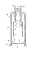
図1は、本実施形態に係るX線発生装置を示す断面図であり、図2は、X線発生装置の分解斜視図である。これら図面に示すX線発生装置1は、ボックスタイプからなる保護ケース2を有し、この保護ケース2は、熱伝導性の高い材料、例えばアルミニウムからなり、4分割されている。すなわち、保護ケース2は、断面コ字状の上蓋3と断面コ字状の下蓋4と平板状の正面パネル5と平板状の背面パネル6とからなり、4分割型のボックスを構成している。また、上蓋3の前端及び後端には、正面パネル5及び背面パネル6の上端を差し込むためのパネル支持溝3a及び3bが形成され、下蓋4の前端及び後端には、正面パネル5及び背面パネル6の下端を差し込むためのパネル支持溝4a及び4bが形成されている。
FIG. 1 is a cross-sectional view showing the X-ray generator according to the present embodiment, and FIG. 2 is an exploded perspective view of the X-ray generator. The X-ray generator 1 shown in these drawings has a
そこで、保護ケース2を組み立てる場合、補強板29の下側を下蓋4の内面にネジ固定した後、下蓋4のパネル支持溝4a,4bに正面パネル5及び背面パネル6の下端をそれぞれ差し込み、上蓋3のパネル支持溝3a,3bに正面パネル5及び背面パネル6の上端を上蓋3のパネル支持溝3a,3bに差し込むようにして、上蓋3と下蓋4とを合わせ、補強板29の上側を上蓋3の内面にネジ固定することで、下蓋4に対して上蓋3をしっかりと固定する。すなわち、保護ケース2は、正面パネル5及び背面パネル6を上蓋3と下蓋4とで挟み込む構造になっているので、この組立て作業性が極めて良い。
Therefore, when assembling the
この保護ケース2内には、軟X線を発生させて静電気の除去等に利用されるX線管8が配置されている。このX線管8は、図3に示すように、コバールガラス製の円筒状バルブ9を有し、このバルブ9の末端には、排気管10をもったステム11が形成され、バルブ9の開放端には、円筒状をなすコバール金属製の出力窓保持部12が融着接続されている。この出力窓保持部12には、その中央開口12aを塞ぐように円板状の出力窓13がAgろう付けにより固定され、出力窓13の内面側には、電子ビームの衝突によりX線を発生させるターゲット14が蒸着されている。
In the
更に、ステム11には2本のステムピン15が固定され、バルブ9内には、所定の電圧で電子ビームを放出するカソードとしてのフィラメント16が設けられ、このフィラメント16は、ステムピン15の先端に固定されている。また、一方のステムピン15には、円筒状をなすステンレス製フォーカス17が固定されている。そして、この出力窓保持部12は、コバール金属からなるので、熱伝導性及び導電性をもち、アースされた保護ケース2に電気的に接続されることで接地電位となり、ターゲット14を接地電位にしている。
Further, two
そこで、X線管8のステムピン15に、後述する電源部21から−9.5kVの高電位を供給し、フィラメント16から接地電位のターゲット14に向けて電子ビームを照射する。このとき、電子ビームの衝突によりターゲット14からX線が放射され、このX線が出力窓13から外部に放出される。このようにX線管8を構成することで直径15mm、長さ30mm程度のバルブ9が可能になり、X線管8は、その全長が40mm程度の超小型になっている。なお、超小型のX線管8のターゲット14は高温になっており、X線の発生効率の維持やターゲットの破損防止のためにターゲット14を冷却する必要がある。
Therefore, a high potential of −9.5 kV is supplied to the
この冷却対策について以下説明する。前述したX線管8には、コバール金属製の出力窓保持部12に一体形成されて、外部に突出するフランジ部18が設けられている。このフランジ部18は、ターゲット14に対して熱的及び電気的に導通状態にあるため、ターゲット14で発生し続ける熱により、出力窓保持部12が100℃前後の高温になり、フランジ部18が加熱されることになる。そこで、図1及び図4に示すように、このフランジ部18は、アルミ製の正面パネル5の内面側に接触固定されている。フランジ部18の熱を保護ケース2に伝えることができ、フランジ部18を接地電位にすることができる。この場合、保護ケース2の正面パネル5には円形のX線照射口5aが設けられ、このX線照射口5aにX線管8の出力窓13を位置合わせすることで、保護ケース2内からのX線の放射を可能にしている。
This cooling measure will be described below. The
また、保護ケース2内には、低電圧発生部19と高電圧発生部20とからなる電源部21が収容されている。この電源部21は、−9.5kVの高電位をステムピン15に供給して、X線管8を駆動させるためのものであり、先ず、低電圧発生部19で、−1kVまで電位を上げ、次に高電圧発生部20で−9.5kVまで電位を上げている。このような電源部21は、鋼製の電源ケース22に固定され、この電源ケース22には、電源部21を収容する部分とは別に、X線管8のバルブ9を収納するためのX線管収容部23が設けられている。このX線管収容部23は、電源部21の側方でこれに隣接する位置に設けられている。その結果、電源部21とX線管収容部23とが並列に配置され、保護ケース2の長さを短くしている。
In the
図4に示すように、電源ケース22には、X線管収容部23の前端を形成し且つ正面パネル5に対して平行に対峙する板状の第1保持板24が設けられ、この第1保持板24には、X線管8のバルブ9を挿入するための開口部24aが形成されている。そこで、この開口部24aにX線管8のバルブ9を挿入した場合、X線管8のフランジ部18は、第1保持板24の前面と第2保持板としての正面パネル5の背面とで挟持される。この場合、電源ケース22は、保護ケース2の下蓋4にネジ固定されているので、X線管8のフランジ部18は、電源ケース22の第1保持板24と、保護ケース2のパネル支持溝3a,4aに固定された正面パネル5とでしっかり挟み付けられることになり、保護ケース2内でしっかりと固定される。
As shown in FIG. 4, the
ここで、第1保持板24と正面パネル(第2保持板)5との間には、熱伝導性を有する中間部材25が設けられ、この中間部材25は、熱伝導性が高く柔軟性をもったシリコンラバーからなる。この中間部材25は、第1保持板24と正面パネル5との間を略埋めるような形状を有すると共に、X線管8のバルブ9を挿入させるための開口部25aを有している。このように、開口部25aに挿入されたX線管8のフランジ部18を、第1保持板24の開口部24aの周縁と正面パネル5の開口部5aの周縁とで挟持した場合、中間部材25の開口部25aの周縁が、X線管8のフランジ部18に接触すると同時に、中間部材25の略全面が、保護ケース2の正面パネル5及び第1保持板24に接触する。その結果、フランジ部18から正面パネル5に伝わる熱伝達経路が実質的に拡張されることになり、アルミ製の保護ケース2での放熱が一層促進されることになる。また、中間部材25は、柔軟性をもっているので、フランジ部18を正面パネル5に圧着させることができ、X線管8に対する衝撃吸収性を高めている。
Here, an
図1及び図2に示すように、X線管収容部23内には、X線管8を保護ケース2内で保持するための振れ止め部材26が設けられ、この振れ止め部材26は、ウレタン樹脂からなると共に、円弧状の押圧面26aでX線管8のバルブ9を挟み込むように2分割されている。そこで、保護ケース2の側壁に固定された保護板29と電源ケース22内の隔壁22aとに各振れ止め部材26を当接させ、円弧状の各押圧面26aでX線管8のバルブ9を挟み込むことで、X線管8を、保護ケース2内にしっかりと保持させることができる。なお、X線発生装置1は、電源部21の低電圧発生部19に所定の電圧を供給するための外部リード線31を有している。この外部リード線31はゴム製のキャップ30をもち、このキャップ30を背面パネル6の開口部6aに嵌め込むことで、外部リード線31は保護ケース2に固定される。また、高電圧発生部20にはカソード用リード線32が設けられ、このリード線32をX線管8のステムピン15に接続することで、−9.5kVの高電圧をフィラメント16に供給している。
As shown in FIGS. 1 and 2, an
次に、第2の実施形態に係るX線発生装置41について説明する。なお、前述したX線発生装置1と同一又は同等の構成については同一の符号を付し、その説明は省略する。
Next, an
図5及び図6に示すように、保護ケース42は細長く形成され、この保護ケース42内には、細長い電源ケース43が収容されている。電源ケース43の前部は、X線管8及び振れ止め部材26を収容するX線管収容部44を有し、電源ケース43の後部は電源部21を有している。このように、電源部21とX線管収容部44とを直列に配置することで、保護ケース42を細長くすることができ、X線発生装置41を狭い場所に設置させる場合に有効である。なお、これ以外の構成、例えば正面パネル5や中間部材25等は、保護ケース42の形状に合わせて小さくなっているだけで、これらの機能や材質は図1に示されたX線発生装置1と同じである。
As shown in FIGS. 5 and 6, the
本発明は、前述した実施形態に限定されるものではなく、例えば、図7に示すように、正面パネル5において、X線照射口5aを形成する周縁部には、フランジ部18を収容させる環状の凹部5bが形成されている。従って、この凹部5bにフランジ部18を嵌め込むことで、正面パネル5に対するフランジ部18の着座性が良くなると同時に、X線管8の出力窓13と正面パネル5のX線照射口5aとの位置合わせが容易となる。また、図示しないが、X線管8のフランジ部18は、正面パネル5に対して接触するようにネジ固定又は接着剤固定されてもよい。
The present invention is not limited to the above-described embodiment. For example, as shown in FIG. 7, in the
1,41…X線発生装置、2,42…保護ケース、5…正面パネル(第2保持板)、8…X線管、9…バルブ、12…出力窓保持部、13…出力窓、14…ターゲット、16…フィラメント(カソード)、18…フランジ部、21…電源部、22,43…電源ケース、23,44…X線管収容部、24…第1保持板、25…中間部材。
DESCRIPTION OF
Claims (3)
前記電源部は鋼製の電源ケースに収納され、前記電源ケースは前記保護ケースに固定されるとともに、
前記出力窓保持部に一体的に形成されて外方に突出するフランジ部を、熱伝導性を有し且つアース可能で、且つ内部に冷却機構を備えることのない前記保護ケースの内側に接触固定させて熱的及び電気的に連結させ、フランジ部を介して前記保護ケースから熱及び電気を外部に逃がすことを可能としたことを特徴とするX線発生装置。 A target that forms a ground potential is fixed to an inner surface of an output window fixed to a conductive and heat conductive output window holding portion provided at the tip of the bulb, and a cathode that irradiates an electron beam toward the target. An X-ray generator for removing static electricity , which contains an X-ray tube that generates soft X-rays and a power supply unit that drives the X-ray tube in parallel in a protective case,
The power supply unit is housed in a steel power supply case, the power supply case is fixed to the protective case,
A flange portion that is integrally formed with the output window holding portion and protrudes outward is fixed to the inside of the protective case that has thermal conductivity, can be grounded, and does not have a cooling mechanism inside. The X-ray generator is characterized in that it can be thermally and electrically connected to release heat and electricity from the protective case to the outside through the flange portion.
Priority Applications (1)
| Application Number | Priority Date | Filing Date | Title |
|---|---|---|---|
| JP2004327926A JP4113177B2 (en) | 2004-11-11 | 2004-11-11 | X-ray generator |
Applications Claiming Priority (1)
| Application Number | Priority Date | Filing Date | Title |
|---|---|---|---|
| JP2004327926A JP4113177B2 (en) | 2004-11-11 | 2004-11-11 | X-ray generator |
Related Parent Applications (1)
| Application Number | Title | Priority Date | Filing Date |
|---|---|---|---|
| JP25678096A Division JP3839528B2 (en) | 1996-09-27 | 1996-09-27 | X-ray generator |
Related Child Applications (1)
| Application Number | Title | Priority Date | Filing Date |
|---|---|---|---|
| JP2007334697A Division JP4391561B2 (en) | 2007-12-26 | 2007-12-26 | X-ray generator |
Publications (3)
| Publication Number | Publication Date |
|---|---|
| JP2005116534A JP2005116534A (en) | 2005-04-28 |
| JP2005116534A5 JP2005116534A5 (en) | 2008-02-14 |
| JP4113177B2 true JP4113177B2 (en) | 2008-07-09 |
Family
ID=34545267
Family Applications (1)
| Application Number | Title | Priority Date | Filing Date |
|---|---|---|---|
| JP2004327926A Expired - Lifetime JP4113177B2 (en) | 2004-11-11 | 2004-11-11 | X-ray generator |
Country Status (1)
| Country | Link |
|---|---|
| JP (1) | JP4113177B2 (en) |
Families Citing this family (15)
| Publication number | Priority date | Publication date | Assignee | Title |
|---|---|---|---|---|
| JP4664025B2 (en) * | 2004-09-02 | 2011-04-06 | 浜松ホトニクス株式会社 | X-ray source |
| JP4889979B2 (en) * | 2005-08-30 | 2012-03-07 | 浜松ホトニクス株式会社 | X-ray source |
| JP4781156B2 (en) * | 2006-04-18 | 2011-09-28 | 株式会社日立メディコ | Transmission X-ray tube |
| KR100823990B1 (en) * | 2007-03-19 | 2008-04-22 | (주)선재하이테크 | A photo ionizer |
| JP2010185665A (en) * | 2009-02-10 | 2010-08-26 | Kobe Steel Ltd | Material for x-ray transmission window, and x-ray transmission window with the material |
| US20120132309A1 (en) | 2010-11-30 | 2012-05-31 | Morris David D | Woven textile fabric and innerduct having multiple-inserted filling yarns |
| JP5796990B2 (en) * | 2011-04-13 | 2015-10-21 | キヤノン株式会社 | X-ray generator and X-ray imaging apparatus using the same |
| JP5580843B2 (en) | 2012-03-05 | 2014-08-27 | 双葉電子工業株式会社 | X-ray tube |
| JP5721681B2 (en) * | 2012-10-02 | 2015-05-20 | 双葉電子工業株式会社 | X-ray tube |
| JP5763032B2 (en) | 2012-10-02 | 2015-08-12 | 双葉電子工業株式会社 | X-ray tube |
| US10254498B2 (en) | 2015-11-24 | 2019-04-09 | Milliken & Company | Partial float weave fabric |
| JP2019075325A (en) * | 2017-10-18 | 2019-05-16 | 浜松ホトニクス株式会社 | X-ray generator |
| CN211151397U (en) | 2018-12-20 | 2020-07-31 | 美利肯公司 | Multi-cavity folding inner conduit structure |
| CN211151396U (en) | 2018-12-20 | 2020-07-31 | 美利肯公司 | Multi-cavity inner conduit structure |
| US11913593B2 (en) | 2021-12-07 | 2024-02-27 | Milliken & Company | Blowable flexible innerduct |
-
2004
- 2004-11-11 JP JP2004327926A patent/JP4113177B2/en not_active Expired - Lifetime
Also Published As
| Publication number | Publication date |
|---|---|
| JP2005116534A (en) | 2005-04-28 |
Similar Documents
| Publication | Publication Date | Title |
|---|---|---|
| JP3839528B2 (en) | X-ray generator | |
| JP4113177B2 (en) | X-ray generator | |
| JP5730497B2 (en) | X-ray generator | |
| WO2018198518A1 (en) | X-ray tube and x-ray generation device | |
| WO2001091160A1 (en) | Light source | |
| KR102470380B1 (en) | X-ray tube and X-ray generator | |
| JP4223863B2 (en) | X-ray generator | |
| JP4391561B2 (en) | X-ray generator | |
| JP2007005319A (en) | X-ray generation device and static eliminator using the same | |
| JP7089396B2 (en) | X-ray generator | |
| JP2007250328A (en) | X-ray tube and x-ray tube device | |
| JP2009021032A (en) | X-ray generating tube | |
| JP2003123999A (en) | X-ray tube device | |
| JP2017168216A (en) | X-rat target and x-ray generating apparatus having the same | |
| JP4829535B2 (en) | X-ray generator and irradiation unit | |
| JP4345447B2 (en) | Light source device | |
| JP4907852B2 (en) | Gas discharge tube | |
| JP4995648B2 (en) | Lamp house and light source device for deuterium lamp | |
| JP2016177922A (en) | Fluorescent light source device | |
| JP2007042434A (en) | X-ray tube | |
| JP7538613B2 (en) | Electron beam source, electron beam irradiation device, and X-ray irradiation device | |
| JP5194261B2 (en) | X-ray tube device | |
| JP2008135397A5 (en) | ||
| JP2022112958A (en) | X-ray module | |
| JP2024115937A (en) | X-ray tube |
Legal Events
| Date | Code | Title | Description |
|---|---|---|---|
| A521 | Written amendment |
Free format text: JAPANESE INTERMEDIATE CODE: A523 Effective date: 20070807 |
|
| A521 | Written amendment |
Free format text: JAPANESE INTERMEDIATE CODE: A523 Effective date: 20071226 |
|
| RD03 | Notification of appointment of power of attorney |
Free format text: JAPANESE INTERMEDIATE CODE: A7423 Effective date: 20071226 |
|
| A131 | Notification of reasons for refusal |
Free format text: JAPANESE INTERMEDIATE CODE: A131 Effective date: 20080129 |
|
| A521 | Written amendment |
Free format text: JAPANESE INTERMEDIATE CODE: A523 Effective date: 20080312 |
|
| TRDD | Decision of grant or rejection written | ||
| A01 | Written decision to grant a patent or to grant a registration (utility model) |
Free format text: JAPANESE INTERMEDIATE CODE: A01 Effective date: 20080408 |
|
| A61 | First payment of annual fees (during grant procedure) |
Free format text: JAPANESE INTERMEDIATE CODE: A61 Effective date: 20080410 |
|
| R150 | Certificate of patent or registration of utility model |
Free format text: JAPANESE INTERMEDIATE CODE: R150 |
|
| FPAY | Renewal fee payment (event date is renewal date of database) |
Free format text: PAYMENT UNTIL: 20110418 Year of fee payment: 3 |
|
| FPAY | Renewal fee payment (event date is renewal date of database) |
Free format text: PAYMENT UNTIL: 20110418 Year of fee payment: 3 |
|
| FPAY | Renewal fee payment (event date is renewal date of database) |
Free format text: PAYMENT UNTIL: 20120418 Year of fee payment: 4 |
|
| FPAY | Renewal fee payment (event date is renewal date of database) |
Free format text: PAYMENT UNTIL: 20140418 Year of fee payment: 6 |
|
| R250 | Receipt of annual fees |
Free format text: JAPANESE INTERMEDIATE CODE: R250 |
|
| EXPY | Cancellation because of completion of term |