JP4111179B2 - Chemical analyzer and chemical analysis system - Google Patents
Chemical analyzer and chemical analysis system Download PDFInfo
- Publication number
- JP4111179B2 JP4111179B2 JP2004231780A JP2004231780A JP4111179B2 JP 4111179 B2 JP4111179 B2 JP 4111179B2 JP 2004231780 A JP2004231780 A JP 2004231780A JP 2004231780 A JP2004231780 A JP 2004231780A JP 4111179 B2 JP4111179 B2 JP 4111179B2
- Authority
- JP
- Japan
- Prior art keywords
- reagent
- analysis
- reaction
- chemical analyzer
- sample
- Prior art date
- Legal status (The legal status is an assumption and is not a legal conclusion. Google has not performed a legal analysis and makes no representation as to the accuracy of the status listed.)
- Expired - Fee Related
Links
Images


Description
本発明は、血液や尿などの生体液や水などの成分分析を行う化学分析装置に係り、特に手術室や救急現場等における緊急検査や、在宅やベッドサイドでの検査や、一般診療所での患者の近くでの迅速検査等、いわゆるPOC(Point-of-Care)テスティングに適した化学分析装置に関する。 The present invention relates to a chemical analyzer that analyzes components such as biological fluids such as blood and urine and water, and in particular, emergency tests in operating rooms and emergency sites, home and bedside tests, and general clinics. The present invention relates to a chemical analyzer suitable for so-called POC (Point-of-Care) testing such as rapid examination near a patient.
従来の血液等の生体液の化学分析装置としては、米国特許第4、451、433号公報に記載の化学分析装置がある。この装置は、血液中の蛋白質、酵素、尿中の成分などを分析・定量するための比色測定部と、血液中のイオンを分析するイオン分析部から構成される装置である。この装置は、一時間に数百テストから、大形の装置になると9000テスト以上の処理速度を持つ。特に、比色測定部では処理速度を上げるために、化学分析装置の本体上面には多数の反応容器がターンテーブルの円周上に設けられ、オーバーラップ処理により順次血液サンプルを混合・反応・計測するシステムである。 As a conventional chemical analyzer for biological fluids such as blood, there is a chemical analyzer described in US Pat. No. 4,451,433. This apparatus is composed of a colorimetric measuring unit for analyzing and quantifying proteins, enzymes, components in urine, and the like, and an ion analyzing unit for analyzing ions in blood. This device has a processing speed of more than 9000 tests when it becomes a large device from several hundred tests per hour. In particular, in order to increase the processing speed in the colorimetric measurement unit, a number of reaction vessels are provided on the circumference of the turntable on the upper surface of the chemical analyzer, and blood samples are sequentially mixed, reacted, and measured by overlap processing. System.
この装置の主要な構成要素は、検体液と試薬を反応容器に供給するための自動サンプル・試薬供給機構と、数十種類の試薬容器を保持しておくための保持部と、反応容器内の血液サンプル・試薬を撹拌するための自動撹拌機構と、反応中あるいは反応が終了した血液サンプルの物性を計測するための計測器と、計測の終了した血液サンプルを吸引・排出し、反応容器を洗浄するための自動洗浄機構や、血液サンプルの持ち越しによる検体間の相互汚染や異なる試薬間の汚染を低減するための自動検体液、試薬供給機構の自動洗浄機構と、これらの動作をコントロールする制御部などを有する。 The main components of this apparatus are an automatic sample / reagent supply mechanism for supplying the sample liquid and the reagent to the reaction container, a holding part for holding several tens of kinds of reagent containers, Automatic stirring mechanism for stirring blood samples and reagents, measuring instrument for measuring physical properties of blood samples during or after reaction, and blood samples that have been measured are aspirated and discharged, and the reaction container is washed Automatic cleaning mechanism for reducing the amount of cross-contamination between samples due to carry-over of blood samples and contamination between different reagents, automatic cleaning mechanism for reagent supply mechanism, and control unit that controls these operations Etc.
対象とする比色測定項目としては数十種類あり、通常の検査項目においても1つの検体に対し、最低でも十種類程度の項目について分析を行う。これらの項目を一つの装置でこなすために、試薬供給機構として、複数の試薬容器から試薬を選択し、所定の試薬量で順次反応容器に供給する、試薬ピペッティング機構と呼ばれる機構が設けられている。試薬ピペッティング機構は主に内部に試薬を吸引して保持するノズルと、そのノズルを3次元的に移動させる機構、試料をノズル内に吸引吐出させるための吸引吐出制御ポンプから構成される。 There are several tens of kinds of colorimetric measurement items to be analyzed, and analysis is performed on at least about ten types of items for one specimen even in normal inspection items. In order to carry out these items with a single device, a mechanism called a reagent pipetting mechanism is provided as a reagent supply mechanism, which selects reagents from a plurality of reagent containers and sequentially supplies them to a reaction container with a predetermined amount of reagent. Yes. The reagent pipetting mechanism mainly includes a nozzle that sucks and holds the reagent inside, a mechanism that moves the nozzle three-dimensionally, and a suction / discharge control pump that sucks and discharges the sample into the nozzle.
また、POCテスティング用の従来技術として、特表平9−504732号公報に記載の血液分析装置がある。本分析装置は、光検知器と制御・信号処理・信号の入出力等を行う分析装置本体と、検体液を導入させて試薬との前処理調整を自動的に行う使い捨て型の遠心式試薬ローター部からなる。まず、検体として血液を円盤の中央部にある導入口に注入する。ローターを本体にセットした後、本体の動作でローターが回転駆動される。この際、遠心作用で血清成分が分離され、かつ所定量の血清が定量されて、ローター内部に予め仕込まれていた希釈液と混合される。さらに停止・回転を繰り返してこの希釈液は周囲に設けられた12個の反応セルに導入される。この反応セルの中には、それぞれ異なる測定項目に対応した乾燥試薬と攪拌用のボールが入れてあり、これにより試薬と希釈液が混合されて所定の反応を開始する。約12分後に、この周囲のセル内の吸光度を本体に内蔵された光検知器が計測する。試薬ローターは、測定項目の組み合わせに応じて何種類か用意されている。 Further, as a conventional technique for POC testing, there is a blood analyzer described in JP-T-9-504732. This analyzer includes an optical detector and an analyzer main body that performs control, signal processing, signal input / output, and the like, and a disposable centrifugal reagent rotor that automatically introduces a sample liquid and performs pretreatment adjustment with a reagent. Consists of parts. First, blood as a specimen is injected into the inlet in the center of the disk. After setting the rotor to the main body, the rotor is driven to rotate by the operation of the main body. At this time, serum components are separated by centrifugal action, and a predetermined amount of serum is quantified and mixed with a diluent previously charged in the rotor. Further, stop and rotation are repeated, and this diluted solution is introduced into 12 reaction cells provided around. In this reaction cell, a dry reagent and a stirring ball corresponding to different measurement items are placed, whereby the reagent and diluent are mixed to start a predetermined reaction. After about 12 minutes, the absorbance in the surrounding cell is measured by a photodetector built in the main body. Several types of reagent rotors are prepared according to combinations of measurement items.
POCテスティングに用いる分析装置には、小型・可搬であること、分析結果が迅速に得られること、扱いが容易であること、いつでも分析可能とするためにメンテナンスがほとんど必要ないこと、さらに診療所など患者に近いところでルーチン検査に用いる場合、検査センタに有償依頼する場合と比較しても十分にコスト競争力のあることが必要となる。 The analyzer used for POC testing is small and portable, that analysis results can be obtained quickly, that it is easy to handle, that little maintenance is required to enable analysis at any time, and that medical care is required. When used for routine examinations near patients such as offices, it is necessary to be sufficiently cost-competitive as compared to the case of requesting a fee from an examination center.
そのため、上記従来技術の分析装置をPOCテスティングに適用する場合、以下に挙げる問題点がある。 Therefore, when the above-described conventional analysis apparatus is applied to POC testing, there are the following problems.
まず第1番目の従来技術では、装置が大型のため、一般にスペースの限られている救急現場や手術室等に設置することが困難である。また、洗浄液や廃液の配管で固定設置されるため、在宅患者やベッドサイドへ移動・持ち運ぶことは不可能である。また、診療所などで利用するには装置コスト、メンテナンスを含めたランニングコストが多大であり経済的ではない。 First, in the first prior art, since the apparatus is large, it is difficult to install it in an emergency site or an operating room where space is generally limited. In addition, since it is fixedly installed with piping for cleaning liquid and waste liquid, it cannot be moved or carried to a home patient or bedside. In addition, when used in a clinic or the like, the apparatus cost and running cost including maintenance are enormous, which is not economical.
次に、第2の従来技術では、第1の従来技術の大型の化学分析装置と比較すると、小型のため手術室等でも設置可能である。また、検体液が連通する部分は全て使い捨てになっているため、洗浄液の供給配管は不要である。そのため、持ち運びも比較的容易で、メンテナンス性も良好である。また、装置コストも低いという特徴がある。ところで、試薬ローターには予めメーカーが決めた測定項目用の試薬が封入されており、実際には不必要な測定項目を同時に計測する場合が多い。従って以下に述べる通り、迅速性とコストの面でPOCテスティングに対して課題となる。 Next, the second prior art can be installed in an operating room or the like because of its small size as compared with the large chemical analyzer of the first prior art. In addition, since all the parts where the sample liquid communicates are disposable, no supply pipe for the cleaning liquid is necessary. Therefore, it is relatively easy to carry and has good maintainability. Also, the device cost is low. By the way, a reagent rotor is filled with a reagent for measurement items determined in advance by a manufacturer, and in practice, unnecessary measurement items are often measured simultaneously. Therefore, as described below, this is a problem for POC testing in terms of speed and cost.
まず第1に、緊急検査において症状に応じて測定したい項目の組み合わせがあっても、上記試薬ローター内にその組み合わせの試薬が入っていなければ、いくつかの試薬ローターを差し替え、入れ替えて順次分析を行う必要があり、結果的に余分な時間がかかってしまう。迅速な検査結果の導出を要求される、緊急検査では大きな問題となる。 First of all, even if there is a combination of items that you want to measure according to symptoms in an emergency test, if there is no reagent in that combination in the reagent rotor, you can replace several reagent rotors and replace them to analyze sequentially. This must be done and results in extra time. This is a major problem in emergency inspections that require quick derivation of inspection results.
第2に予め分析項目が固定化されているために、本来分析する必要のない項目まで分析することや、不要な分析をしない場合でも、一度他の測定に使用した試薬ロータは廃棄される。このため、余分に費用をかけることになり、コスト競争力のある検査センタへの依頼費用に対して、経済性の点で劣っている。医療費の削減により、より一層の検査コストの圧縮が重要となっている現在、在宅・ベッドサイド、診療所等での普及に対して隘路となる。 Secondly, since the analysis items are fixed in advance, the reagent rotor used once for other measurements is discarded even if the analysis is performed up to the items that do not need to be analyzed or the unnecessary analysis is not performed. For this reason, extra costs are incurred, which is inferior in terms of economy with respect to the cost for requesting a cost-competitive inspection center. At present, it is important to further reduce the cost of examination due to the reduction of medical costs.
以上から本発明の目的は、分析項目に応じた試薬を、ユーザーが任意に設定可能で、小型・可搬かつ洗浄液・廃液等の配管を必要としないメンテナンス容易な化学分析装置を提供することにある。 From the above, an object of the present invention is to provide a chemical analyzer that can be arbitrarily set by a user according to an analysis item, is small and portable, and does not require piping such as cleaning liquid and waste liquid, and is easy to maintain. is there.
上記課題を解決するために、本発明は、試薬と検体液を混合し、前記検体液中の成分と前記試薬を反応させ、その成分の濃度を計測する化学分析装置において、前記検体液が注入される導入部と、前記導入部から注入された前記検体液を分配する分岐流路と、前記分岐流路の各々に対応して設けられた複数の流路と、前記複数の流路上に設けられ、前記検体液の検査に使用する量を規定する定量部と、前記複数の流路の各々に対応して設けられ、前記定量部で定量化された前記検体液を保持し前記試薬と混合し反応させる複数の反応部とを有する保持担体と、前記保持担体を搭載して移動させる駆動部と、前記複数の反応部の各々に異なる種類の試薬を順次吐出する試薬吐出手段と、前記試薬と前記検体液とを混合後、成分を検出する検出部とを備え、前記定量部は、前記定量部を移動させることで前記規定された量が前記複数の反応部の各々へ送られるように構成され、前記分岐流路と前記複数の流路とが各々分離して構成される。
In order to solve the above problems, the present invention is to mix reagent and the specimen solution, the component with the reagent of the test solution is reacted, in a chemical analysis apparatus for measuring the concentration of that component, wherein the specimen liquid injection and introducing part is a branch channel for distributing the sample fluid injected from the inlet portion, and a plurality of flow passages provided corresponding to each of the branch flow path, provided in the plurality of flow path A quantification unit for defining an amount to be used for the test of the sample liquid , and the sample liquid quantified by the quantification unit, provided corresponding to each of the plurality of flow paths, and mixed with the reagent A holding carrier having a plurality of reaction parts to be reacted, a driving part for mounting and moving the holding carrier, a reagent discharge means for sequentially discharging different types of reagents to each of the plurality of reaction parts, and the reagent Detection unit that detects components after mixing the sample liquid Wherein the quantifying section is configured such that the amount of the defined by moving the quantitative portion is sent to each of the plurality of reaction sections, the branch flow path and the plurality of flow paths each Configured separately.
本発明により、分析項目に応じた試薬を、ユーザーが任意に設定可能で、小型・可搬かつ洗浄液・廃液等の配管を必要としないメンテナンス容易な化学分析装置を提供することが可能となる。 According to the present invention, it is possible to provide a chemical analyzer that can be arbitrarily set by a user according to an analysis item, is small and portable, and does not require piping such as a cleaning liquid and a waste liquid, and is easy to maintain.
本発明の一実施形態を図1〜図3を用いて説明する。図1は本発明の化学分析装置の実施例の全体構成図、図2は本発明で用いる試薬秤量吐出ポンプの説明図、図3は使い捨て型の分析カセットの構成図、図4から図6は本発明の別の分析カセットの形態を示す構成図、また図7、8は本発明の別の実施例の全体構成図を示す。 An embodiment of the present invention will be described with reference to FIGS. FIG. 1 is an overall configuration diagram of an embodiment of a chemical analyzer of the present invention, FIG. 2 is an explanatory diagram of a reagent weighing discharge pump used in the present invention, FIG. 3 is a configuration diagram of a disposable analysis cassette, and FIGS. The block diagram which shows the form of another analysis cassette of this invention, and FIG. 7, 8 show the whole block diagram of another Example of this invention.
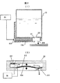
図1〜図3を用いて本発明の化学分析装置の構成について説明する。図1は本化学分析装置の要素全体構成配置を斜め上方から見た図を示している。 The configuration of the chemical analyzer of the present invention will be described with reference to FIGS. FIG. 1 is a diagram showing the overall configuration of the chemical analyzer as viewed from obliquely above.
本実施例の分析装置は、大きく2つの要素から成る。使い捨ての試薬や検体液を一時的に保持するための領域を備えた保持担体である分析カセット1と、分析カセット1を装填する分析装置本体2である。分析装置本体2は、分析カセット1を一時的に係止する保持担体係止手段を備えた位置調整を行う位置調整手段であるリニア駆動部21と、リニア駆動部21の上部にあって、分析カセット1に所定量の試薬を吐出する試薬吐出手段である試薬秤量吐出ポンプ22を備えた試薬ボトル23列と、リニア駆動部21の最も左側に設けられている光検出器24と、分析項目等の設定、試薬ボトル23の設置順序等の情報を記録し、かつ分析結果の表示・記録を行う信号処理部25と、信号処理部25からの動作手順の指示を受けてリニア駆動部21や試薬秤量吐出ポンプ22および光検出器24に制御信号を送出するコントローラ26とから成る。試薬秤量吐出ポンプ22から試薬3が後述する分析カセット1に設けた反応セルに供給される。
The analyzer of this embodiment is mainly composed of two elements. An
次に、図2を用いて本実施例の試薬秤量吐出ポンプ22および本ポンプを付加した試薬ボトル23の構成を説明する。試薬ボトル23の底部には孔231が設けてある。その孔231に連通するように、図2(2)に示すダイヤフラム型の試薬秤量吐出ポンプ22が設けられている。試薬秤量吐出ポンプ22には入口と出口に、一方向のみ流れるチェック弁221、222が設けられている。また、ポンプ室にはダイヤフラム223があり、外側の面に振動板224が貼り付けられている。この振動板224の両端には、電圧を印加するための配線が設けられている。ダイヤフラム型の試薬秤量吐出ポンプ22の出口は、下方に向かって開放しており、吐出流れをスムーズにするためのノズル225が設けられている。振動板224の配線は、試薬秤量吐出ポンプ22を保持するホルダー226内に設けられた電気接点227と駆動用配線で接続されている。
Next, the configuration of the reagent weighing and discharging
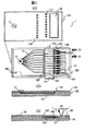
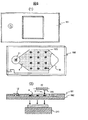
次に、図3を用いて本発明の分析カセット1の構成について説明する。分析カセット1は大きく分けて2つの基板から構成されている。1つは反応セル16等を備えた検出用基板182と、検出用基板182の上部に設けられる上部基板181とからなる。この分析カセットの大きさは、幅約55mm長さ約90mmの名刺サイズである。
Next, the configuration of the
上部基板181には検体液を導入するための注射器41と契合する導入孔11´と、後述の各微少流路13、145の端部に設けた空気抜き用の微少孔131、142に連通する空気孔131´、142´と、反応部に試薬を供給したり、分析を行うため検出用の切欠き部19からなる。この上部基板181は、検出用基板182に接着剤等で固定される。
In the
本実施例の分析カセット1の検出用基板182には、検体液を導入するための一つの検体の導入部11が設けてある。導入部11は上部基板181の導入孔11´と連通している。導入部11の下方には血球成分に対して流動抵抗を与え、
血清成分を優先的に通過させるフィルター12が設けられている。フィルター12の後に設けられた流路は、分岐して10本の細い微小流路13に別れている。各々の微少流路13の末端は第1の微小孔131が設けられており、上部基板8に設けた微少孔131´を介して大気に開放されている。
The
A
これらの微少流路13の途中には、スライドさせることで一定量の血清を切り取りすることができるスライド式定量バルブ14が組み込まれている。バルブ内の微小流路141は、血清が注入されスライド式定量バルブ14の微少流路141内に血清が充満されるまでは微少流路13に連結している。血清が充満すると、全体がスライドしてもう一方の微小流路145に嵌め込まれる。この微小流路145の上流側の末端は、第2の微小孔142から上部基板8の微少孔142´を介して大気に開放されている。もう一方の下流端には液体を保持する領域又は部位に試験紙15が設けられている。ここで、試験紙15とは紙あるいは繊維状の物質で形成されていても良く、血清や試薬を担持でき、白色のある面積を持つ吸湿性の物質であれば良い。試験紙15はそのまま延長して反応セル16内に展開されている。
In the middle of these
反応セル16の上部は開放された窓になっている。なお、本実施例では、上部基板8の反応セル16に対向する部分は切欠かれて窓19になっている。分析カセット1が未使用のときはこの上部基板8側の切欠き部はシール部材でふさがれており、塵埃等が反応セルに入り込まないようにして有り、使用時にシールをはがす構成としている。この上部基板8の反応セル16に対向する部分をスライドして開口できる窓としても良いことは言うまでもない。この窓19を通して、試薬3が試験紙15に吐出される。10個ある反応セル16の内、図中で最も下側にあるセルには血清中の電解質を計測するための電極161が設けられており、コネクタ部162との間をカセット内部の信号線で繋がれている。
The upper part of the
以上の構成で本装置は以下のように動作する。 With the above configuration, the present apparatus operates as follows.
まず血球を含んだ血液4(全血)を注射器41を用いて分析カセット1の導入部11から内部に送出する。その際フィルター12によって血球成分より血清成分が優先的に内部の流路に入る。血清成分は分岐した10本の微小流路13内を注射器41の圧力と毛細管力によって加圧され、スライド式定量バルブ14の微少流路141を通って第1の微小孔131まで満たされる。この状態で手操作又は自動によってスライド式定量バルブ14の一端を図3中矢印143の方向に押す。これにより、微小流路141の部分がもう一方の微少流路145に嵌め込まれる。スライド式定量バルブ14内の微小流路141の容積は一定であり、高精度な定量採取が行われる。本実施例では定量バルブ内の微小流路の寸法は0.2mm角、長さ7.5mmの流路が形成されており、これにより0.3μlの微量血清が高精度に定量採取される。当然ながら採取量は前記微小流路141の寸法を調整することで任意に設定可能である。
First,
スライド式定量バルブ14内の微小流路141に嵌め込まれた一定量の血清は、もう一方の出口にある試験紙15端によって吸引され、反応セル16内の試験紙15部分までまんべんなく広がる。この時点で分析カセット1内の各試験紙15には定量された血清4が浸透した状態となる。この分析カセット1を装置本体2のリニア駆動部21にセットする。
A certain amount of serum fitted in the
信号処理部25からスタートの入力を与えると、予め設定しておいた測定項目の順に試薬ボトル群の中から試薬ボトル23が順次選定され、その下部に分析カセット1の反応セル16がリニア駆動部21により移動する。その後、コントローラ26の制御信号により試薬ボトル23の下部に設けられた試薬秤量吐出ポンプ22が動作して、所定量の試薬3が反応セル16の試験紙15片を狙って吐出される。同様の動作で、順次隣の反応セル16に対しても異なる試薬3が吐出されていく。
When the start input is given from the
9番目と10番目の反応セル16には希釈液が所定量吐出される。試験紙15では、毛細管現象により試薬3がまんべんなく試験紙15片に広がるため、ほぼ均一に斑なく試薬3と血清4が混合・反応する。この状態で放置すると、各試験紙15では反応が進行し、発色あるいは発光が始まる。一定時間毎にリニア駆動部21が作動して分析カセット1の各試験紙15部分を光検知器24下部に移動させる。光検知器24では試験紙15上のスペクトル強度や発光強度を随時測定する。また9番目のセルについては希釈された血清自体の吸収スペクトルが測定される。10番目のセルは電解質センサ161により血清中のイオン濃度が検出される。
A predetermined amount of diluent is discharged into the ninth and
以上のように、適宜リニア駆動部21が並行移動して各反応セル16での反応過程をモニタすることで、大型の自動分析装置と同等の精度で計測が可能である。計測が終了した分析カセット1は使い捨てとする。
As described above, the
先に述べたように、従来の化学分析装置で、使い捨て型のユニットを利用しているものでは、測定項目が既にメーカーによって決められている。そのため、本当に必要な分析項目の組み合わせの結果を得るまでに複数のユニットに亙って繰り返し分析したり、あるいは不必要な項目まで計測することになり、不経済である。 As described above, in a conventional chemical analyzer using a disposable unit, the measurement items are already determined by the manufacturer. For this reason, it is uneconomical to repeatedly perform analysis over a plurality of units until a result of a combination of analysis items that are really necessary is obtained, or to measure unnecessary items.
それに対して、本実施例の化学分析装置では、使い捨ての分析カセット1を使用しているため、メンテナンス性、取り扱い性、可搬性等を損なうことなく、かつユーザーが独自に検査項目を任意に選択することができる。すなわち、まずユーザーの使用環境に応じて頻繁に利用される項目の試薬ボトル23を分析装置本体2に選定・装着する。次に、分析の前に装着された試薬ボトル23の中から更に最適な組み合わせを選択して測定することができる。また、血液を使用する部品(分析カセット)は、全て使い捨てとなっているため洗浄液・廃液等の処理を行うこともなく、メンテナンスが容易である。さらに、本実施例の効果として分析カセット1の構造は同じ形状・大きさ・仕様のため大量生産によりカセットコストも著しく低減可能となる。
In contrast, the chemical analyzer of the present embodiment uses a
次に図4を用いて本発明の第2の実施例について説明する。 Next, a second embodiment of the present invention will be described with reference to FIG.
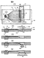
分析装置本体2は図1の実施例と同様である。第1の実施例とは、分析カセット1での血清4の定量採取方法および試薬供給方法・検出方式が異なる。図4(1)に示すように本実施例の分析カセット1は血液4の導入部11に続いてロータリーバルブ17を設け、スライド式定量バルブ14を不要にして有る。すなわち、ロータリーバルブ17に放射状に分配流路171を形成して、ここで分岐を行うと共に定量計測もここで行うようにしている。血液の導入時はロータリーバルブ17は微少流路13とは連結されていない状態とし、ロータリーバルブ17中に設けた分岐路中に血液が充満してから回転させて微少流路13と連結させる。
The analyzer
図4(2)に示すように、微小流路13の途中には段差を持って拡大する部分132が設けて有る。拡大部分132に連結して反応セル16が設けられている。反応セル16の上部には薄い膜162が形成されており、注射針226によって容易に穿孔できるようになっている。また反応セル16の前後には反応セル16への光の導入・出射用の反射部163が設けられている。前記ロータリーバルブ17は放射状の分配流路171の他に、それと対称の位置に圧縮空気を送るための通路172も設けてある。さらに、圧縮空気を送るための空気注入用の注射器も用意されている。但し、ロータリーバルブ17の回転は本実施例では手操作で行うことになっているが、装置本体に自動的に回転させる機構を持たせてもかまわない。また前記圧縮空気の供給も装置本体から自動で行ってもよい。本実施例では試薬秤量吐出ポンプ22にはノズル225の代わりに、穿孔用の注射針226を備えている。また装置本体のリニア駆動部21には分析カセット1を昇降させるための機構も備えている。
As shown in FIG. 4 (2), a
以上の構成で次のように動作する。まず、分析カセット1を装置本体2のリニア駆動部21にセットする。リニア駆動部21は、所定の試薬ボトル23の下方位置に分析カセット1の反応セル16が位置するように移動する。次に上昇して、前記穿孔用の注射針226を反応セル16の上部の膜162に突き刺す。この状態で試薬秤量吐出ポンプ22を動作させ、所定量の試薬3を注射針226を通して反応セル16内に注入する。この動作を、他の9個の反応セル16についても同様に行う。
With the above configuration, the operation is as follows. First, the
その後、図4(3)に示すように、分析カセット1を装置本体2から取り出し、検体の導入部11に検体液である血液4の入った注射器41を充て、滴下する。フィルタ12経て血清のみが微小流路13に分配される。血清は微小流路13の段差部分132まで毛細管現象により進入するが、段差のためのその場所で進行が停止する。
Thereafter, as shown in FIG. 4 (3), the
その後、図4(3)に示すように、ロータリーバルブ17を回転させ微小流路13の上流側を圧縮空気用の通路172に連結するように切り替える。これにより、微小流路13内の血清4が一定量採取される。さらに、圧縮空気を送り込むための注射器を導入部11に充て、空気を通路に送り込むことで、血清は各反応セル16内に放出される。この血清の放出流れと、それに続く空気の勢いで血清と試薬3の混合が促進される。
Thereafter, as shown in FIG. 4 (3), the rotary valve 17 is rotated so that the upstream side of the
次に、この分析カセット1を再び装置本体2のリニア駆動部21に装填する。
混合が前の動作で不十分であれば、場合によっては図4(4)に示すように、反応セル内に超音波を放射する攪拌器164に接触させて音響的に混合させてもかまわない。反応が進み、発色を呈するようになると、第1の実施例と同様、逐次反応セル16内の吸収スペクトル、あるいは発光を検出する。
Next, the
If mixing is insufficient in the previous operation, in some cases, as shown in FIG. 4 (4), the mixing may be carried out acoustically by contacting an
この場合、図4(5)に示すように、光検知器24を分析カセット1の下側に配置し、反応セル16の前後に設けられた反射部163に光を照射することで、反応セル16内の液面下に光を透過させることができ、液面での泡などの影響を受けない高精度な計測が可能となる。
In this case, as shown in FIG. 4 (5), the
次に、図5を用いて第3の実施例の説明する。本実施例の装置構成は第1の実施例と概略同じである。異なるのは、分析カセット1の第2の微小孔142位置で試薬秤量吐出ポンプ22のノズル225が直接密着するように、リニア駆動部21に昇降機構を設けた点である。このため、分析カセット1の上部基板の検査用基板の反応部に対応する個所に切欠き窓を設ける必要がない。
Next, a third embodiment will be described with reference to FIG. The apparatus configuration of this embodiment is substantially the same as that of the first embodiment. The difference is that an elevating mechanism is provided in the
図5(2)に示すように、第1の実施例と同様、分析カセット1においてスライド式定量バルブ14で所定量の血清を採取した後、分析カセット1を装置本体2のリニア駆動部21に装填する。本実施例では試薬秤量吐出ポンプ22のノズル225が直接分析カセット1の第2の微小孔142に密着する。この状態で試薬3を吐出すると図5(3)に示すように、試薬3は血清を押し出しながら反応セル16内に放出される。この放出時の流れで試薬3と血清が混合される。反応セル16内の空気は空気孔165により外部に放出されるようになっているため、圧縮されることはない。その後は、第1及び2の実施例と同様、反応セル16前後の反射部163を利用してスペクトル強度や発光強度が計測される。
As shown in FIG. 5 (2), as in the first embodiment, after a predetermined amount of serum is collected with the slide-
図6を用いて第4の実施例の説明する。第4の実施例では分析カセット1に一枚の平面状の反応セル18が設けている。また第1の実施例における分析装置本体2の光検知器24に代えて、高精度なテレビカメラ241を設けてある。さらに、リニア駆動部21は、分析カセット1を2次元的に平面移動させる機構としている。上部基板8はこの反応セル18に対向する部分が切欠かれている。
A fourth embodiment will be described with reference to FIG. In the fourth embodiment, a single
まず、導入部11から注入された血液4はフィルター12を通過して血清のみが前記平面状セル18に広がる。この状態で、分析カセットを装置本体2のリニア駆動部21に装填する。リニア駆動部21は分析カセット1を2次元的に移動させて、平面状の反応セル18の所定の位置に所定の試薬秤量吐出ポンプ22のノズル225を位置せしめる。この状態で、試薬3を一定量吐出させる。同様の動作を行って図6(1)に示すように、一定の間隔を保ったままマトリックス状に異なる試薬を吐出していく。各吐出位置185では打ち込まれた試薬3と周りの血清との境界において徐々に拡散混合が進行していく。微小領域であれば、この進行は濃度勾配に依存した分子拡散のみが支配しており、再現性の良い混合が達成される。
First, the
この試薬3と血清の境界面で発生する混合反応を、テレビカメラ241で捕らえて反応過程を測定する。予め時間と拡散の度合いを検定しておけば、混合比を規定することができ、そこでの発色・発光状態から溶存物質の濃度を推定することができる。本実施例の分析カセット1は、他の実施例と比較して簡易な構造であり、製造コストを抑えることができる。また、マトリックス状に吐出する間隔を狭め、試薬の吐出量を微量化することで極めて多くのスポットを形成させることができ、一度に多くの項目を同時に計測できるという特徴が得られる。
The mixing reaction occurring at the interface between the
前記第1から第4の実施例では、分析カセット1を大きく2の基板から構成されることで説明をしてきたが、上部基板は必ずしも必要ではなく検査用基板だけで構成しても良い。この場合、検査用基板の血液注入用の導入部11の形状を注射器の吐出口と合わせた形状とし、反応セル16の部分は未使用時はシール等でカバーをしておく必要がある。なお、これら各基板はプラスチック等の樹脂材料で形成することができる。
In the first to fourth embodiments, the
図7に本発明の第5の実施例に関する化学分析システムの構成図を示す。本発明のシステムは、第1の実施例の分析装置本体を、分析カセットに試薬を装填する試薬装填専用装置5(試薬ボトル、試薬秤量吐出ポンプ群とリニア駆動部および信号処理部、コントローラから成る)と、分析カセットの分析を専用で行う分析端末装置6(リニア駆動部と光検知器から成る)に分けたものである。分析端末装置6は複数セット以上設置される。 FIG. 7 shows a configuration diagram of a chemical analysis system according to the fifth embodiment of the present invention. The system of the present invention comprises the analyzer main body of the first embodiment, and a reagent loading dedicated device 5 (reagent bottle, reagent weighing discharge pump group, linear drive unit, signal processing unit, and controller) for loading a reagent into an analysis cassette. ) And an analysis terminal device 6 (consisting of a linear drive unit and a light detector) that performs the analysis of the analysis cassette exclusively. A plurality of sets of analysis terminal devices 6 are installed.
本システムは以下のように使用される。まず、各ユーザーの希望に応じて試薬装填専用装置5を用いて分析カセット1に予め試薬3を装填する。こうすることで、ユーザーの検査業務に近いところで、希望の分析項目にカスタマイズされた分析カセット1が多数製作できる。各ユーザーの手元には分析端末装置5のみがあり、予め充填され準備した分析カセット1に血液4を導入し分析のみを行う。
このような分析システムでは、分析端末装置6自体のコストは低減され、より多くのユーザーに配備することが可能となる。当然のことながら、これらの端末6間、試薬装填装置5間をネットワークで結ぶことで、分析カセット1の過不足情報、製造状況等をモニタすること、さらに計測データの相互通信による分析値の信頼性向上等に役立てることが可能となる。
The system is used as follows. First, the
In such an analysis system, the cost of the analysis terminal device 6 itself is reduced, and it can be deployed to more users. Naturally, by connecting the terminals 6 and the
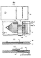
図8に本発明の第6の実施例を示す。基本的な構成は第1の実施例と同じである。第1から第5の実施例では分析カセット1は長方形形状しているが、本実施例では分析カセット1を円盤形状とした点が異なる。本実施例では、当然ながら中央に血液の導入部11を持たせ、放射状に微小流路13を設けている。本構成とすることで、試薬容器23と試薬秤量吐出ポンプ22とをリニア駆動し、分析カセット1は回転駆動すれば良く、光検知の高速化が図れる。
FIG. 8 shows a sixth embodiment of the present invention. The basic configuration is the same as in the first embodiment. In the first to fifth embodiments, the
1…分析カセット、2…分析装置本体、3…試薬、4…血液、5…試薬装填専用装置、6…分析端末装置、11…導入部、13…微小流路、14…スライド式定量バルブ、15…試験紙、16…反応セル、17…ロータリーバルブ、18…反応セル、21…リニア駆動部、22…試薬秤量吐出ポンプ、23…試薬ボトル、24…光検知器、25…信号処理器、26…コントローラ、161…電解質センサ、225…ノズル。
DESCRIPTION OF
Claims (4)
前記検体液が注入される導入部と、前記導入部から注入された前記検体液を分配する分岐流路と、前記分岐流路上に設けられ、前記検体液の検査に使用する量を規定する定量部と、前記分岐流路の各々に対応して設けられた複数の流路と、前記複数の流路の各々に対応して設けられ、前記定量部で定量化された前記検体液を保持し前記試薬と混合し反応させる複数の反応部とを有する保持担体と、
前記保持担体を搭載して移動させる駆動部と、
前記複数の反応部の各々に異なる種類の試薬を順次吐出する試薬吐出手段と、
前記試薬と前記検体液とを混合後、成分を検出する検出部とを備え、
前記定量部は、前記定量部を移動させることで前記規定された量が前記複数の反応部の各々へ送られるように構成され、
前記分岐流路と前記複数の流路とが各々分離して構成されたことを特徴とする化学分析装置。 In a chemical analyzer that mixes a reagent and a sample solution, reacts the component in the sample solution with the reagent, and measures the concentration of the component,
And introducing part the sample fluid is injected, and the branch flow path for distributing the sample fluid injected from the inlet portion, provided in the branch flow path, quantitative defining the amount to be used for inspection of the sample fluid A plurality of flow paths provided corresponding to each of the branch flow paths, and the sample liquid quantified by the quantification section provided corresponding to each of the plurality of flow paths. A holding carrier having a plurality of reaction parts mixed and reacted with the reagent;
A drive unit for mounting and moving the holding carrier;
Reagent discharge means for sequentially discharging different types of reagents to each of the plurality of reaction units;
A detector for detecting a component after mixing the reagent and the sample liquid;
The quantitative unit is configured such that the defined amount is sent to each of the plurality of reaction units by moving the quantitative unit.
A chemical analyzer characterized in that the branch channel and the plurality of channels are separated from each other.
前記反応部には吸湿性のある繊維状物質を設けたことを特徴とする化学分析装置。 In claim 1,
A chemical analyzer characterized in that a hygroscopic fibrous material is provided in the reaction part.
前記導入部と前記分岐流路との間あるいは、前記分岐流路の途中にあって前記検体液中の固形成分を分離除去するフィルターを備えたことを特徴とする化学分析装置。 In claim 1,
A chemical analyzer comprising a filter that separates and removes a solid component in the sample liquid between the introduction part and the branch channel or in the middle of the branch channel.
前記反応部の少なくとも一つに前記検体液中のイオン濃度を計測するイオンセンサを備えたことを特徴とする化学分析装置。 In claim 1,
A chemical analyzer comprising an ion sensor for measuring an ion concentration in the sample liquid in at least one of the reaction units.
Priority Applications (1)
| Application Number | Priority Date | Filing Date | Title |
|---|---|---|---|
| JP2004231780A JP4111179B2 (en) | 2004-08-09 | 2004-08-09 | Chemical analyzer and chemical analysis system |
Applications Claiming Priority (1)
| Application Number | Priority Date | Filing Date | Title |
|---|---|---|---|
| JP2004231780A JP4111179B2 (en) | 2004-08-09 | 2004-08-09 | Chemical analyzer and chemical analysis system |
Related Parent Applications (1)
| Application Number | Title | Priority Date | Filing Date |
|---|---|---|---|
| JP07141599A Division JP3984748B2 (en) | 1999-03-17 | 1999-03-17 | Chemical analyzer and chemical analysis system |
Publications (3)
| Publication Number | Publication Date |
|---|---|
| JP2004325462A JP2004325462A (en) | 2004-11-18 |
| JP2004325462A5 JP2004325462A5 (en) | 2006-04-27 |
| JP4111179B2 true JP4111179B2 (en) | 2008-07-02 |
Family
ID=33509462
Family Applications (1)
| Application Number | Title | Priority Date | Filing Date |
|---|---|---|---|
| JP2004231780A Expired - Fee Related JP4111179B2 (en) | 2004-08-09 | 2004-08-09 | Chemical analyzer and chemical analysis system |
Country Status (1)
| Country | Link |
|---|---|
| JP (1) | JP4111179B2 (en) |
Families Citing this family (25)
| Publication number | Priority date | Publication date | Assignee | Title |
|---|---|---|---|---|
| WO2008053751A1 (en) * | 2006-11-01 | 2008-05-08 | Shimadzu Corporation | Reaction container plate and its reaction processing equipment |
| JP4771225B2 (en) * | 2006-12-14 | 2011-09-14 | セイコーエプソン株式会社 | Dispensing device |
| JP5012817B2 (en) * | 2007-02-05 | 2012-08-29 | 株式会社島津製作所 | Reaction vessel plate and reaction processing method |
| US9308530B2 (en) | 2007-03-02 | 2016-04-12 | Shimadzu Corporation | Reaction container plate and reaction treatment apparatus |
| US20100062446A1 (en) * | 2007-04-13 | 2010-03-11 | Nobuhiro Hanafusa | Reactor plate and reaction processing method |
| WO2008132871A1 (en) * | 2007-04-13 | 2008-11-06 | Shimadzu Corporation | Reaction container plate and reaction treatment method |
| JP4947140B2 (en) * | 2007-04-13 | 2012-06-06 | 株式会社島津製作所 | Reaction vessel plate and reaction processing method |
| JP4894684B2 (en) * | 2007-08-31 | 2012-03-14 | 株式会社島津製作所 | Reaction vessel plate and reaction processing method |
| JP4962227B2 (en) * | 2007-08-31 | 2012-06-27 | 株式会社島津製作所 | Reaction vessel plate and reaction processing method using the reaction vessel plate |
| JP4962248B2 (en) * | 2007-10-02 | 2012-06-27 | 株式会社島津製作所 | Reaction vessel plate and reaction processing method |
| JP4962249B2 (en) * | 2007-10-02 | 2012-06-27 | 株式会社島津製作所 | Reaction vessel plate and reaction processing method |
| JP4900485B2 (en) * | 2007-11-15 | 2012-03-21 | 株式会社島津製作所 | Reaction vessel plate and reaction processing method |
| JP4883188B2 (en) * | 2007-12-04 | 2012-02-22 | 株式会社島津製作所 | Reaction vessel and reaction processing method |
| JP4872922B2 (en) * | 2008-01-07 | 2012-02-08 | 株式会社島津製作所 | Reaction vessel |
| WO2009087857A1 (en) * | 2008-01-07 | 2009-07-16 | Shimadzu Corporation | Reaction container |
| JP4872923B2 (en) * | 2008-01-07 | 2012-02-08 | 株式会社島津製作所 | Reaction vessel |
| JP4872921B2 (en) * | 2008-01-07 | 2012-02-08 | 株式会社島津製作所 | Reaction vessel |
| JP4946918B2 (en) * | 2008-02-28 | 2012-06-06 | 株式会社島津製作所 | Reaction vessel plate and reaction processing method |
| JP4924516B2 (en) * | 2008-04-02 | 2012-04-25 | 株式会社島津製作所 | Reaction vessel plate and reaction processing method |
| JP5136225B2 (en) * | 2008-06-04 | 2013-02-06 | 株式会社島津製作所 | Reaction vessel plate and reaction processing method |
| JP5239552B2 (en) * | 2008-06-26 | 2013-07-17 | 株式会社島津製作所 | Reaction vessel plate and reaction processing method |
| FR2938062B1 (en) * | 2008-11-05 | 2014-02-28 | Biomerieux Sa | DEVICE FOR PREPARING AND / OR PROCESSING A BIOLOGICAL SAMPLE |
| CN107764825A (en) * | 2017-11-17 | 2018-03-06 | 三诺生物传感股份有限公司 | Centrifuge reagent disc and the detection means containing the centrifugation reagent disc |
| JP7219093B2 (en) * | 2019-01-09 | 2023-02-07 | 株式会社フコク | microfluidic chip |
| CN113970626B (en) * | 2021-09-30 | 2024-04-02 | 武汉新烽光电股份有限公司 | Water quality detection equipment and detection method |
-
2004
- 2004-08-09 JP JP2004231780A patent/JP4111179B2/en not_active Expired - Fee Related
Also Published As
| Publication number | Publication date |
|---|---|
| JP2004325462A (en) | 2004-11-18 |
Similar Documents
| Publication | Publication Date | Title |
|---|---|---|
| JP3984748B2 (en) | Chemical analyzer and chemical analysis system | |
| JP4111179B2 (en) | Chemical analyzer and chemical analysis system | |
| JP5433139B2 (en) | Microchemical analyzer, measuring method thereof, and microcassette | |
| US9091699B2 (en) | Microfluid testing system with a multiple-channel disc and utility thereof | |
| US8114351B2 (en) | Analysis system and method for the analysis of a body fluid sample for an analyte contained therein | |
| JP4969060B2 (en) | Automatic analyzer | |
| US20050220668A1 (en) | Disposable test device with sample volume measurement and mixing methods | |
| JP2006518449A (en) | Microfluidic biochip with a breakable seal | |
| JP2007155491A (en) | Micro reactor system and liquid feed method | |
| US7318359B2 (en) | Sampling means and system for testing a sample liquid | |
| AU2016295622B2 (en) | Fluidic system for performing assays | |
| JP6723409B2 (en) | Analysis chip and sample analyzer | |
| JP6590795B2 (en) | Sample analyzer | |
| WO2015174431A1 (en) | Sample analysis device | |
| CN113278509B (en) | Chip device for nucleic acid detection | |
| JP2008101984A (en) | Chip having measurement section and method of measuring liquid sample using the chip | |
| CN114453037A (en) | Homogeneous test micro-fluidic chip and detection system | |
| KR20210155460A (en) | Rt-pcr device | |
| US20050100922A1 (en) | Fluid analyzing apparatus | |
| JP2009085818A (en) | Liquid reagent built-in type microchip | |
| JP2022107553A (en) | Inspection chip measuring device | |
| KR20220112960A (en) | Volumetric chip and method for detecting analyte using the same | |
| TW201600601A (en) | A multiple-channel microfluid disc testing method | |
| JP2008286733A (en) | Sealed-type reactor and reaction detector |
Legal Events
| Date | Code | Title | Description |
|---|---|---|---|
| A521 | Written amendment |
Free format text: JAPANESE INTERMEDIATE CODE: A523 Effective date: 20060314 |
|
| A621 | Written request for application examination |
Free format text: JAPANESE INTERMEDIATE CODE: A621 Effective date: 20060314 |
|
| RD01 | Notification of change of attorney |
Free format text: JAPANESE INTERMEDIATE CODE: A7421 Effective date: 20060421 |
|
| A131 | Notification of reasons for refusal |
Free format text: JAPANESE INTERMEDIATE CODE: A131 Effective date: 20070918 |
|
| A521 | Written amendment |
Free format text: JAPANESE INTERMEDIATE CODE: A523 Effective date: 20071119 |
|
| A131 | Notification of reasons for refusal |
Free format text: JAPANESE INTERMEDIATE CODE: A131 Effective date: 20071218 |
|
| A521 | Written amendment |
Free format text: JAPANESE INTERMEDIATE CODE: A523 Effective date: 20080218 |
|
| TRDD | Decision of grant or rejection written | ||
| A01 | Written decision to grant a patent or to grant a registration (utility model) |
Free format text: JAPANESE INTERMEDIATE CODE: A01 Effective date: 20080318 |
|
| A61 | First payment of annual fees (during grant procedure) |
Free format text: JAPANESE INTERMEDIATE CODE: A61 Effective date: 20080331 |
|
| FPAY | Renewal fee payment (event date is renewal date of database) |
Free format text: PAYMENT UNTIL: 20110418 Year of fee payment: 3 |
|
| FPAY | Renewal fee payment (event date is renewal date of database) |
Free format text: PAYMENT UNTIL: 20120418 Year of fee payment: 4 |
|
| FPAY | Renewal fee payment (event date is renewal date of database) |
Free format text: PAYMENT UNTIL: 20120418 Year of fee payment: 4 |
|
| FPAY | Renewal fee payment (event date is renewal date of database) |
Free format text: PAYMENT UNTIL: 20130418 Year of fee payment: 5 |
|
| FPAY | Renewal fee payment (event date is renewal date of database) |
Free format text: PAYMENT UNTIL: 20130418 Year of fee payment: 5 |
|
| FPAY | Renewal fee payment (event date is renewal date of database) |
Free format text: PAYMENT UNTIL: 20140418 Year of fee payment: 6 |
|
| LAPS | Cancellation because of no payment of annual fees |