JP4110940B2 - Liquid storage container with nozzle - Google Patents
Liquid storage container with nozzle Download PDFInfo
- Publication number
- JP4110940B2 JP4110940B2 JP2002334082A JP2002334082A JP4110940B2 JP 4110940 B2 JP4110940 B2 JP 4110940B2 JP 2002334082 A JP2002334082 A JP 2002334082A JP 2002334082 A JP2002334082 A JP 2002334082A JP 4110940 B2 JP4110940 B2 JP 4110940B2
- Authority
- JP
- Japan
- Prior art keywords
- nozzle
- liquid storage
- liquid
- storage container
- tip
- Prior art date
- Legal status (The legal status is an assumption and is not a legal conclusion. Google has not performed a legal analysis and makes no representation as to the accuracy of the status listed.)
- Expired - Fee Related
Links
Images


Landscapes
- Bag Frames (AREA)
Description
【0001】
【発明の属する技術分野】
本発明は、袋状に形成したノズル付き液体収納容器に関する。
【0002】
【従来の技術】
液体注出部付き液体収納容器の一種類として、液体洗剤、液体柔軟剤、液体石鹸等の詰め替え用内容物に使用される袋状柔軟性包装体(パウチ)が数々市場に提供されている。その中で、スタンディングパウチ、即ち、立て置き式液体収納容器において、詰め替え時の注ぎ易さを改良した技術として、プラスチックフィルムをヒートシールして形成したノズル部を有する注出機能付き包装袋において、ノズル部に膨らみ部5を設け、ノズル部5の両側の下端部、或いはその近傍から包装袋の内方に向かう第1谷折り線6を設け、第1谷折り線6の交点或いはその近傍から下方に第2谷折り線7を設けると共に、第2谷折り線7の両側に山折り線8を設けた構成がある(特許文献1参照)。
【0003】
【特許文献1】
特開2000−177756号公報(第2〜3頁、図1〜2)
【0004】
【発明が解決しようとする課題】
特許文献1は、それ以前のものからすれば、ノズル部の開口状態の改善は見られるが、ノズル部の開口を十分に保つという観点から、第1谷折り線6、第2谷折り線7、山折り線8はかなり深く形成され、各折り線部分での破損防止のために、包装袋のフィルムを厚くする等の改善とそれに伴うコストアップ等の問題がある。また山折れ線と谷折れ線の複数の折り線形成のために加工が複雑である。更に、各折り線部分が際立って目立ち、包装袋のノズル部分に皺が寄った状態になって見栄えが悪くなる問題がある。
【0005】
本発明は、このような点に鑑みて、特定された単純な折れ線によって、特別に厚いプラスチック製フィルム又はシートでなくても、ノズル部が良好に開き、外観上も良好なノズル付き液体収納容器を提供するものである。
【0006】
【課題を解決するための手段】
本発明の立て置き式のノズル付き液体収納容器は、表裏一対のプラスチック製フィルム又はシートの上辺部、左右の側辺部および底部を巡る周辺部をシールして内部に液体収納部を形成し、前記上辺部と前記左右側辺部の一方の側辺部とのコーナ部に斜め上方に向くように両側のサイドシールにて液体注出用ノズルを形成して下部が膨らみ上部が窄んだ立て置き式のノズル付き液体収納容器において、前記ノズルの表面及び裏面の相対する位置には、前記ノズルの先端部から前記液体収納部方向へ向かう経路に前記ノズルの中央部を外側に膨らます直線状の凸状筋と、前記凸状筋の下側の前記ノズル部分のみに前記ノズルの先端部から前記液体収納部方向へ向かう経路に内側へ窪ませる凹状筋とを形成し、前記凹状筋は、前記ノズルの先端部から前記ノズルの下側の前記サイドシールの根元部へ向かって、このサイドシールの長さよりも短い長さでもって前記凸状筋との間隔が次第に大きくなるように形成されたものである。
【0007】
この構成において、液体詰め替えのために詰め替え先の容器の口にノズルを差し込むことにより、ノズル両側のサイドシール部が詰め替え先の容器の口縁によって接近する方向へ押される。ノズルはその中央部分の凸状筋によって外方へ膨らむが、ノズルの下側には凹状筋が存在することによって、この凹状筋とその近傍部分がノズル内方へ突出し易く、そのためにノズルの下側のサイドシール部が詰め替え先容器の口縁で押されることによって、凹状筋とその近傍部分がノズル内方へ差し込まれつつ凸状筋を中心とした外方への屈曲が形成され、ノズルの開きが良好となる。この場合、詰め替え先容器の口縁によってサイドシール部が真っ直ぐの方向に押される場合は表裏一対の凹状筋とその近傍部分がノズル内方へ差し込むが、サイドシール部が詰め替え先容器の口縁によって倒れた状態となる場合は、その倒れた側の凹状筋とその近傍部分がノズル内方へ差し込むようになり、いずれの場合も、ノズルを良好に開く作用をする。
【0008】
また、前記凸状筋は直線状に形成され、前記凹状筋は、前記ノズルの先端部から前記ノズルの下側の前記サイドシールの根元部へ向かって、このサイドシールの長さよりも短い長さでもって前記凸状筋との間隔が次第に大きくなるように形成されることによって、ノズルの先端が詰め替え先容器の口縁によって押されるとき、注出口部がその後方部に比して広く開きやすくなり、結果として液体の良好な注出が達成される。
【0011】
また、前記凸状筋の下側の前記サイドシールの根元部の近傍から前記凸状筋の延長下方部の前記液体収納部へ向かう経路に内側へ窪ませる上弦湾曲の凹状筋を形成したことを特徴とする。
【0012】
この構成によって、ノズルの下側のサイドシール部が詰め替え先の容器の口縁によって押されて、凸状筋を中心とした外方への屈曲が形成されるとき、この上弦湾曲の凹状筋に沿った谷が形成され、これによって、ノズル根元部分の開き具合が良好となる。
【0013】
【発明の実施の形態】
次に、本発明の実施の形態について説明する。各図は本発明のノズル付き液体収納容器の実施形態を示しており、図1は本発明のノズル付き液体収納容器の正面図、図2は本発明のノズル部分の斜視図、図3は本発明のノズル部分の変化状態の説明図、図4は本発明のノズルに形成した凸状エンボスの断面図、図5は本発明のノズル付き液体収納容器の液体詰め替え状態説明図、図6は図1のA−A断面図である。
【0014】
先ず、本発明のノズル付き液体収納容器の構成を図に基づき説明する。液体収納容器1は、その中に充填される液体内容物としては、液体洗剤、液体柔軟剤、液体石鹸、その他があり、他のプラスチックス容器等の容器へ液体内容物を詰め替える詰め替え用として用いられる袋状柔軟性包装体(パウチ)であり、底部を下にしてテーブル等の上に立てて置くことができる、スタンディングパウチと称される立て置き式のノズル付き液体収納容器である。この液体収納容器1は、面対応に位置された一対のプラスチック製フィルム又はシートの周辺部をシールして一部分に液体注出用ノズルを形成した構成である。その具体的な構成は、面対応に位置された表面材2と裏面材3、及び底面材4を後述のように周辺部でヒートシールして袋状に構成したものであり、表面材2、裏面材3及び底面材4はそれぞれ透明材、不透明材、半透明材のいずれかのプラスチック製フィルム又はシートで構成される。
【0015】
このフィルム又はシートの構成は、例えば、外側層がナイロンフィルム、内側層が線状低密度ポリエチレンフィルムからなる二層構造のもの、また外側層が二軸延伸ナイロンフィルム、中間層が一軸延伸ポリオレフィンフィルム、内側層が線状低密度ポリオレフィンからなる三層構造のもの、また外側層がナイロンフィルム、中間層がアルミニウム真空蒸着ポリエチレンテレフタレートフィルム、内側層が線状低密度ポリエチレンフィルムからなる三層構造のもの、また、外側層が酸化アルミニウム蒸着ポリエチレンテレフタレートフィルム、中間層がナイロンフィルム、内側層が線状低密度ポリエチレンフィルムからなる三層構造のもの、また、外側層がポリエチレンテレフタレートフィルム、外側中間層がアルミニウム箔、内側中間層がナイロンフィルム、内側層が線状低密度ポリエチレンフィルムからなる四層構造等の構成である。
【0016】
表面材2と裏面材3相互の周辺接合シール部5と、表面材2と裏面材3のそれぞれの下部と前後に広がった底面材4の接合シール部6とは、それぞれヒートシールされ、表面材2と裏面材3の間には、底部が前後に広がった液体収納部7を液体収納容器1の内部に形成している。この構成によって液体収納部7の底面6Aは図1に示すように上弦の湾曲形状をなす。また、前記フィルム又はシートの構成として、外側層を透明とし、中間層をアルミニウム又はその他の無機化合物を真空蒸着法等の方法によって蒸着して無機化合物蒸着層を設けたバリア性フィルムとし、外観が銀色等を呈する液体収納容器1とすることもできる。
【0017】
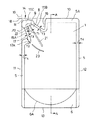
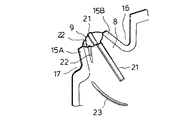
このように、液体収納容器1は、表面材2と裏面材3を構成するプラスチック製フィルム又はシートの上辺部10、左側辺部11、右側辺部12および底部13を巡る周辺部をシールして内部に液体収納部7を形成し、上辺部の一方コーナ部14(以下、図のように左上コーナ部に設けた形態で説明する)に先端の注出口部9に向かって先細り形状をなす液体注出用ノズル8を形成した下部が膨らみ上部が窄んだ立て置き式ノズル付き液体収納容器である。ノズル8の根本部の両側には上方へV字状に開いた上部窪み16と側方へV字状に開いた側部窪み17が形成された状態である。窪み16、17は、その底部に丸みを持たせることによって、この底部から裂けることを防止している。
【0018】
次に、本発明に係るノズル付き液体収納容器1の具体的な構成を図に基づき説明する。液体収納容器1は、上辺部10、左側辺部11、右側辺部12および底部13を巡る周辺部と、ノズル8の周辺部、即ち両側のサイドシール15A、15B及び先端シール部15Cとをシールして、底部が前後に広がった形状の液体収納部7を形成するが、この場合、液体収納容器1内への液体の充填のために、上部窪み16と右側辺部12の上端部との間の部分5Aを残して他の周辺接合シール部5と6がシールされる。この状態で液体収納容器1内への液体の充填は、通常、工場において、未シール部5Aに形成される表面材2と裏面材3間の開口へ液体注入ノズルを挿入して行われる。この充填の後に、内容物充填用収納部7の脱気を行い、未シール部5Aはヒートシールされる。このようにして液体が充填された液体収納容器1は、立て置き状態において、底部が前後に膨らんだ形状をなし、図6のように上辺部は脱気によって表面材2と裏面材3とが密着または接触状態となる。
【0019】
表面材2と裏面材3は、ノズル部、即ち、ノズル8とその両側のサイドシール15A、15B及び先端シール部15Cとを含めたノズル部分が、シール上辺部10の端部延長線18と左側辺部11の端部延長線19が交差する領域R内に収まるような形態に形成されている。若しこの領域Rから突出する長さであれば、表面材2と裏面材3の材料取りが悪くなる。また、液体を充填した状態の液体収納容器1を多数梱包する場合や取り扱い上からしてノズル8が邪魔になり、梱包箱が大きくなったり、箱詰めする場合の取り扱いが不便となるが、ノズル8が領域R内に収まる長さに形成されているため、そのようなことはない。
【0020】
ノズル8の先端部に注出口部9を形成する場合は、図1に点線で示すようにノズル8周辺のシール部を切断する。このためにサイドシール15A、15Bの一方を切り込んで形成したノッチ20から表面材2と裏面材3を手で引き裂くことによって注出口部9を形成でき、はさみ等の工具なしに注出口部9を切断形成できる構成である。
【0021】
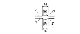
表面材2と裏面材3には、ノズル8の表面及び裏面の相対する位置に、ノズル8の先端部から(詳しくは注出口部9から)液体収納部7方向へ向かう経路にノズル8の中央部を外側に膨らます凸状筋21を形成している。凸状筋21は、ノズル8の内側から外側へ向けてV字状又はU字状に膨らむ山型筋(山型すじ)に形成する形態でもよいが、図4に示すようにノズル8の内側から外側に向けて幅が狭くなる台形状をなす凸状エンボス形態とすることもできる。この凸状エンボスは、その幅T5が3〜10mm、T6は5〜10mmでもってノズル8の良好な開きを得ることができる。
【0022】
また、凸状筋21の下側のノズル部分には、ノズル8の先端部(詳しくは注出口部9から)から液体収納部7方向へ向かう経路にノズル8の内側へV字状又はU字状に窪ませる凹状筋(凹状すじ)22を形成している。
【0023】
この構成において、注出口部9を切断形成した後、液体詰め替えのために詰め替え先の容器30の口にノズル8を差し込む。これにより、ノズル8両側のサイドシール部15A、15Bが詰め替え先の容器30の口縁31によって接近する方向へ押される。ノズル8はその中央部分の凸状筋21によって図3の矢印のように外方へ膨らむが、ノズル8の下側には凹状筋22が存在することによって、この凹状筋22とその近傍部分がノズル8内方へ突出し易くなる。そのため、ノズル8の下側のサイドシール部15Aが詰め替え先容器30の口縁31で押されることによって、凹状筋22とその近傍部分が図3の矢印のようにノズル8内方へ差し込まれつつ凸状筋21を中心とした外方への屈曲が形成され、ノズル8の開きが良好となる。
【0024】
この場合、詰め替え先容器30の口縁31によってサイドシール部15A、15Bが真っ直ぐの方向に押される場合は表裏一対の凹状筋22とその近傍部分がノズル8内方へ差し込むが、通常、ノズル8のサイドシール部15Aが下側になるようにして詰め替え先容器30の口にノズル8が差し込まれるため、サイドシール部15Aが詰め替え先容器30の口縁31によって倒れることがある。また口の小さい詰め替え先容器30の場合は、サイドシール部15Aが詰め替え先容器30の口縁31によって倒れることがある。その倒れた側、例えば図3で右側へ倒れた場合は図3の右側の凹状筋22とその近傍部分がノズル内方へ差し込むようになる。いずれの場合も、ノズルを良好に開く作用をする。
【0025】
また、本発明のノズル付き液体収納容器は、凸状筋21は直線状に形成され、凸状筋21の下側のノズル部分に形成する凹状筋22は、ノズル8の先端部(詳しくは注出口部9から)からサイドシール15Aの根元部へ向かって凸状筋21との間隔Tが次第に大きくなるように形成している。このため、ノズル8の先端が詰め替え先容器30の口縁31によって押されるとき、注出口部9がその後方部に比して広く開きやすくなり、結果として液体の良好な注出が達成される。
【0026】
また、本発明のノズル付き液体収納容器のノズル8は、両側のサイドシール15A、15Bの根元部に形成した側辺部側の窪み17と上辺部側の窪み16とによってコーナ部14に斜め上方に向くように区画形成され、ノズル8の表面及び裏面の相対する位置には、ノズル8の先端部から液体収納部7方向へ直線状に向かう経路にノズル8の中央部を外側に膨らます凸状筋21と、凸状筋21の下側のノズル部分にあってノズル8の先端部(詳しくは注出口部9から)から液体収納部7方向へ向かう経路に内側へ窪ませる凹状筋22とを形成し、側辺部側窪み17の底シール部17Aのシール幅T2をノズル8両側のサイドシール15A、15Bのシール幅T3及び一方の側辺部11のシール幅T4よりも広くしている。なお、T3≦T4である。
【0027】
このように、側辺部側窪み17の底部のシール面積が大きく取れることによって、上記の作用効果に加えて、サイドシール部15A、15Bが詰め替え先容器30の口縁31によって倒れるとき、この側辺部側窪み17底部のシール幅T2の広い部分が突っ張り作用をなし、サイドシール部15Aは、このシール幅T2の広い部分を支点としてその先側(注出口部9側)が凹状筋22を軸とした倒れ状態となる。この場合、その倒れた側、例えば図3で右側へ倒れた場合は図3の右側の凹状筋22とその近傍部分がノズル8内方へ差し込み易くなり、ノズル8の開きが更に良好となる。このため、口の小さい詰め替え先容器30への詰め替えも良好となる。
【0028】
また、本発明のノズル付き液体収納容器は、サイドシール15Aの根元部から液体収納部7へ向かう経路に液体収納容器1の内側へV字状又はU字状に窪ませる上弦湾曲の凹状筋(凹状すじ)23を形成している。
【0029】
この構成によって、ノズル8下側のサイドシール部15Aが詰め替え先の容器30の口縁31によって押されて、凸状筋21を中心とした外方への屈曲が形成されるとき、この下方へ膨らむ形状の上弦湾曲の凹状筋23に沿った谷が形成され、これによって、ノズル8の根元部分の開き具合が良好となる。
【0030】
本発明のノズル付き液体収納容器は、従来技術で述べたような複雑な折り線を形成することなく、表裏のフィルム又はシートの密着によるノズルの閉塞を防止してノズルの良好な開きを達成できるため、表裏のフィルム又はシートへのダメージが少なく、外観デザイン的にも好ましい形態となる。
【0031】
上記において、直線状の凸状筋21、直線状の凹状筋22及び上弦湾曲の凹状筋23は、いずれも型押しによって形成することができる。
【0032】
本発明は、上記実施形態に限定されず、本発明の技術的範囲を逸脱しない限り種種の変更が考えられ、それに係る種種の実施形態を包含するものである。
【0033】
【発明の効果】
請求項1の発明によると、ノズルの下側のサイドシール部が詰め替え先容器の口縁で押されることによって、凹状筋とその近傍部分がノズル内方へ差し込まれつつ凸状筋を中心とした外方への屈曲が形成され、ノズルの開きが良好となる。そして、詰め替え先容器の口縁によってノズル両側のサイドシール部が相互に接近する真っ直ぐの方向に押される場合は、表裏一対の凹状筋とその近傍部分がノズル内方へ差し込むが、通常、ノズル下方のサイドシール部が下側になるようにして詰め替え先容器の口にノズルが差し込まれるため、このサイドシール部が詰め替え先容器の口縁によって倒れることがある。また口の小さい詰め替え先容器の場合は、このサイドシール部が詰め替え先容器の口縁によって倒れることがある。その場合、倒れた側の凹状筋とその近傍部分がノズル内方へ差し込むようになり、ノズルを良好に開く作用をする。更に、凸状筋は直線状に形成され、凹状筋は、ノズルの先端部からノズルの下側のサイドシールの根元部へ向かって、このサイドシールの長さよりも短い長さでもって凸状筋との間隔が次第に大きくなるように形成されることによって、ノズルの先端が詰め替え先容器の口縁によって押されるとき、注出口部がその後方部に比して広く開きやすくなり、結果として液体の良好な注出が達成される。
【0036】
また、請求項2の発明によると、ノズル下側のサイドシール部が詰め替え先の容器の口縁によって押されて、凸状筋を中心とした外方への屈曲が形成されるとき、この下方へ膨らむ形状の上弦湾曲の凹状筋に沿った谷が形成され、ノズルの根元部分の開き具合が良好となる。
【0037】
本発明のノズル付き液体収納容器は、従来技術で述べたような複雑な折り線を形成することなく、表裏のフィルム又はシートの密着によるノズルの閉塞を防止してノズルの良好な開きを達成できるため、表裏のフィルム又はシートへのダメージが少なく、外観デザイン的にも好ましい形態となる。
【図面の簡単な説明】
【図1】本発明のノズル付き液体収納容器の正面図である。
【図2】本発明のノズル部分の斜視図である。
【図3】本発明のノズル部分の変化状態の説明図である。
【図4】本発明のノズルに形成した凸状エンボスの断面図である。
【図5】本発明のノズル付き液体収納容器の液体詰め替え状態説明図である。
【図6】図1のA−A断面図である。
【符号の説明】
1・・・・液体収納容器
2・・・・表面材
3・・・・裏面材
4・・・・底面材
5・・・・周辺接合シール部
6・・・・接合シール部
7・・・・液体収容部
8・・・・ノズル
9・・・・注出口部
10・・・・上辺部
11・・・・左側辺部
12・・・・右側辺部
13・・・・底部
14・・・・コーナ部
15A、15B・・・・サイドシール部
16・・・・上辺部側窪み
17・・・・側辺部側窪み
17A・・・・側辺部側窪みの底シール部
18・・・・窪みのノズル側の壁
20・・・・ノッチ
21・・・・凸状筋
22・・・・凹状筋
23・・・・上弦湾曲の凹状筋[0001]
BACKGROUND OF THE INVENTION
The present invention relates to a liquid storage container with a nozzle formed in a bag shape.
[0002]
[Prior art]
As one type of liquid storage container with a liquid pouring part, a lot of bag-like flexible packaging bodies (pouches) used for refilling contents such as liquid detergents, liquid softeners, liquid soaps, etc. are provided on the market. Among them, as a technique for improving the ease of pouring at the time of refilling in a standing pouch, that is, a standing-type liquid storage container, in a packaging bag with a dispensing function having a nozzle portion formed by heat sealing a plastic film, A bulging
[0003]
[Patent Document 1]
Japanese Unexamined Patent Publication No. 2000-177756 (
[0004]
[Problems to be solved by the invention]
In
[0005]
In view of these points, the present invention provides a liquid container with a nozzle that has a nozzle that opens well and has a good appearance, even if it is not a specially thick plastic film or sheet, due to the specified simple broken line. Is to provide.
[0006]
[Means for Solving the Problems]
The standing-type nozzle-equipped liquid storage container of the present invention forms a liquid storage part inside by sealing the peripheral part around the upper side part, the left and right side parts and the bottom part of a pair of front and back plastic films or sheets, A liquid pouring nozzle is formed by side seals on both sides so as to face obliquely upward at the corner portion of the upper side portion and one of the left and right side portions, and the lower portion is swollen and the upper portion is narrowed In a stationary liquid storage container with a nozzle, a linear shape in which the central portion of the nozzle swells outward in a path from the tip of the nozzle toward the liquid storage portion is opposed to the front and back surfaces of the nozzle . a convex muscles, to form a concave muscle recessing inward path towards the liquid containing portion direction from the tip of the nozzle only in the nozzle portion of the lower side of the convex muscle, the concave muscle, the Nozzle tip Toward the root portion of the side seal of the lower al the nozzle, a distance between the convex muscle with a length shorter than the length of the side seal and is formed so as gradually increases.
[0007]
In this configuration, by inserting the nozzle into the mouth of the refill destination container for liquid refilling, the side seal portions on both sides of the nozzle are pushed in a direction approaching the mouth of the refill destination container. The nozzle bulges outward due to the convex streaks in its central part, but the presence of concave streaks on the lower side of the nozzle makes it easy for the concave streaks and its neighboring parts to protrude inwardly. By pushing the side seal part on the side at the mouth of the refilling destination container, the concave stripe and the vicinity thereof are inserted inward of the nozzle, and an outward bend around the convex stripe is formed. Opening is good. In this case, when the side seal part is pushed in a straight direction by the mouth of the refill destination container, the pair of front and back concave stripes and the vicinity thereof are inserted into the nozzle, but the side seal part is pushed by the mouth of the refill destination container. In a fallen state, the recessed streaks on the fallen side and the vicinity thereof are inserted into the inside of the nozzle, and in either case, the nozzle opens favorably.
[0008]
The convex streak is formed in a straight line, and the concave streak is shorter than the length of the side seal from the tip of the nozzle toward the root of the side seal below the nozzle. Therefore, when the tip of the nozzle is pushed by the lip of the refill destination container, the spout portion is easier to open than the rear portion thereof by forming the gap with the convex streaks gradually larger. As a result, good liquid dispensing is achieved.
[0011]
In addition, a concave streak of an upper chord curve that is recessed inwardly in a path from the vicinity of the base portion of the side seal below the convex streak to the liquid storage part in the extended lower part of the convex streak is formed. Features.
[0012]
With this configuration, when the side seal portion on the lower side of the nozzle is pushed by the mouth of the container to be refilled to form an outward bend centered on the convex muscle, A valley along the line is formed, whereby the degree of opening of the nozzle base portion is improved.
[0013]
DETAILED DESCRIPTION OF THE INVENTION
Next, an embodiment of the present invention will be described. Each figure shows an embodiment of a liquid storage container with a nozzle of the present invention, FIG. 1 is a front view of the liquid storage container with a nozzle of the present invention, FIG. 2 is a perspective view of a nozzle portion of the present invention, and FIG. FIG. 4 is a cross-sectional view of a convex emboss formed on the nozzle of the present invention, FIG. 5 is a liquid refill state explanatory diagram of a liquid container with a nozzle of the present invention, and FIG. It is AA sectional drawing of 1. FIG.
[0014]
First, the structure of the liquid storage container with a nozzle of the present invention will be described with reference to the drawings. The
[0015]
This film or sheet is composed of, for example, a two-layer structure in which the outer layer is a nylon film and the inner layer is a linear low density polyethylene film, the outer layer is a biaxially stretched nylon film, and the intermediate layer is a uniaxially stretched polyolefin film. Three-layer structure with inner layer made of linear low-density polyolefin, outer layer with nylon film, intermediate layer with aluminum vacuum-deposited polyethylene terephthalate film, inner layer with three-layer structure made of linear low-density polyethylene film Also, the outer layer is an aluminum oxide-deposited polyethylene terephthalate film, the intermediate layer is a nylon film, the inner layer is a three-layer structure consisting of a linear low density polyethylene film, the outer layer is a polyethylene terephthalate film, and the outer intermediate layer is aluminum. Foil, inner middle layer Nylon film, a configuration of a four-layer structure in which the inner layer is made of linear low density polyethylene film.
[0016]
The peripheral
[0017]
As described above, the
[0018]
Next, a specific configuration of the nozzle-containing
[0019]
The
[0020]
When the spout 9 is formed at the tip of the
[0021]
The
[0022]
Further, the lower nozzle portion of the
[0023]
In this configuration, after the spout portion 9 is cut and formed, the
[0024]
In this case, when the
[0025]
Further, in the liquid storage container with a nozzle according to the present invention, the
[0026]
Further, the
[0027]
Thus, when the
[0028]
In addition, the liquid storage container with a nozzle according to the present invention has an upper-curved curved streak that is recessed in a V shape or U shape inside the
[0029]
With this configuration, when the
[0030]
The liquid storage container with a nozzle according to the present invention can achieve a good opening of the nozzle by preventing the nozzle from being blocked by the adhesion of the front and back films or sheets without forming a complicated folding line as described in the prior art. For this reason, there is little damage to the film or sheet on the front and back sides, and this is a preferable form in terms of appearance design.
[0031]
In the above, the straight
[0032]
The present invention is not limited to the above-described embodiments, and various modifications can be considered without departing from the technical scope of the present invention, and the various embodiments related thereto are included.
[0033]
【The invention's effect】
According to the invention of
[0036]
According to the invention of
[0037]
The liquid storage container with a nozzle according to the present invention can achieve a good opening of the nozzle by preventing the nozzle from being blocked by the adhesion of the front and back films or sheets without forming a complicated folding line as described in the prior art. For this reason, there is little damage to the film or sheet on the front and back sides, and this is a preferable form in terms of appearance design.
[Brief description of the drawings]
FIG. 1 is a front view of a liquid container with a nozzle according to the present invention.
FIG. 2 is a perspective view of a nozzle portion of the present invention.
FIG. 3 is an explanatory diagram of a change state of a nozzle portion according to the present invention.
FIG. 4 is a cross-sectional view of a convex emboss formed on the nozzle of the present invention.
FIG. 5 is an explanatory diagram of a liquid refill state of the liquid storage container with a nozzle according to the present invention.
6 is a cross-sectional view taken along the line AA in FIG.
[Explanation of symbols]
DESCRIPTION OF
Claims (2)
Priority Applications (1)
| Application Number | Priority Date | Filing Date | Title |
|---|---|---|---|
| JP2002334082A JP4110940B2 (en) | 2002-11-18 | 2002-11-18 | Liquid storage container with nozzle |
Applications Claiming Priority (1)
| Application Number | Priority Date | Filing Date | Title |
|---|---|---|---|
| JP2002334082A JP4110940B2 (en) | 2002-11-18 | 2002-11-18 | Liquid storage container with nozzle |
Publications (2)
| Publication Number | Publication Date |
|---|---|
| JP2004168333A JP2004168333A (en) | 2004-06-17 |
| JP4110940B2 true JP4110940B2 (en) | 2008-07-02 |
Family
ID=32698623
Family Applications (1)
| Application Number | Title | Priority Date | Filing Date |
|---|---|---|---|
| JP2002334082A Expired - Fee Related JP4110940B2 (en) | 2002-11-18 | 2002-11-18 | Liquid storage container with nozzle |
Country Status (1)
| Country | Link |
|---|---|
| JP (1) | JP4110940B2 (en) |
Cited By (4)
| Publication number | Priority date | Publication date | Assignee | Title |
|---|---|---|---|---|
| JP2011184065A (en) * | 2010-03-08 | 2011-09-22 | Toppan Printing Co Ltd | Refilling container |
| WO2014054694A1 (en) | 2012-10-03 | 2014-04-10 | 凸版印刷株式会社 | Refillable container |
| JP2014201040A (en) * | 2013-04-09 | 2014-10-27 | 凸版印刷株式会社 | Package and method for manufacturing the same |
| JP7439678B2 (en) | 2020-07-27 | 2024-02-28 | 日本精機株式会社 | position detection device |
Families Citing this family (12)
| Publication number | Priority date | Publication date | Assignee | Title |
|---|---|---|---|---|
| JP4612391B2 (en) * | 2004-10-20 | 2011-01-12 | 大日本印刷株式会社 | Self-supporting bag with spout |
| JPWO2007011009A1 (en) * | 2005-07-22 | 2009-02-05 | 味の素株式会社 | Liquid storage bag |
| JP5272288B2 (en) * | 2006-03-23 | 2013-08-28 | 凸版印刷株式会社 | Pouch with spout |
| JP5128463B2 (en) * | 2008-12-26 | 2013-01-23 | 株式会社吉野工業所 | Thin container |
| JP5702056B2 (en) * | 2009-06-19 | 2015-04-15 | 凸版印刷株式会社 | Refill container |
| JP5957808B2 (en) * | 2011-05-27 | 2016-07-27 | 凸版印刷株式会社 | Refill container |
| JP6316533B2 (en) * | 2012-05-01 | 2018-04-25 | 大日本印刷株式会社 | Refillable pouch |
| JP5854160B2 (en) * | 2014-03-27 | 2016-02-09 | 凸版印刷株式会社 | Refillable packaging bag and method for manufacturing the same |
| WO2016129129A1 (en) * | 2015-02-13 | 2016-08-18 | 凸版印刷株式会社 | Refilling package bag |
| JP6911887B2 (en) * | 2015-06-08 | 2021-07-28 | 凸版印刷株式会社 | Storage container |
| JP6554920B2 (en) * | 2015-06-08 | 2019-08-07 | 凸版印刷株式会社 | Storage container |
| JP7119513B2 (en) * | 2018-04-05 | 2022-08-17 | 凸版印刷株式会社 | liquid pouch |
Family Cites Families (2)
| Publication number | Priority date | Publication date | Assignee | Title |
|---|---|---|---|---|
| JP2000043902A (en) * | 1998-07-27 | 2000-02-15 | Lion Corp | Liquid storage pouch |
| JP3307363B2 (en) * | 1998-10-05 | 2002-07-24 | 東洋製罐株式会社 | Packaging bag with pouring function |
-
2002
- 2002-11-18 JP JP2002334082A patent/JP4110940B2/en not_active Expired - Fee Related
Cited By (6)
| Publication number | Priority date | Publication date | Assignee | Title |
|---|---|---|---|---|
| JP2011184065A (en) * | 2010-03-08 | 2011-09-22 | Toppan Printing Co Ltd | Refilling container |
| WO2014054694A1 (en) | 2012-10-03 | 2014-04-10 | 凸版印刷株式会社 | Refillable container |
| KR20150066529A (en) | 2012-10-03 | 2015-06-16 | 도판 인사츠 가부시키가이샤 | Refillable container |
| US10040609B2 (en) | 2012-10-03 | 2018-08-07 | Toppan Printing Co., Ltd. | Refill container |
| JP2014201040A (en) * | 2013-04-09 | 2014-10-27 | 凸版印刷株式会社 | Package and method for manufacturing the same |
| JP7439678B2 (en) | 2020-07-27 | 2024-02-28 | 日本精機株式会社 | position detection device |
Also Published As
| Publication number | Publication date |
|---|---|
| JP2004168333A (en) | 2004-06-17 |
Similar Documents
| Publication | Publication Date | Title |
|---|---|---|
| JP4110940B2 (en) | Liquid storage container with nozzle | |
| JP5887695B2 (en) | Bag with spout | |
| JPH05330561A (en) | Simple container substituted for bottle | |
| JP3336966B2 (en) | Packaging bag with pouring function | |
| JPH0577838A (en) | Simple vessel substituted for bottle | |
| JPH1159704A (en) | Liquid-packaging bag with reinforced spout | |
| JP5789969B2 (en) | Refill container | |
| JP4887576B2 (en) | Liquid storage container with nozzle | |
| JP3422093B2 (en) | Simple self-standing bag | |
| JP4876561B2 (en) | Bag with spout | |
| JP2007210629A (en) | Bag with spout | |
| JP4060930B2 (en) | Refillable pouch | |
| JP3912083B2 (en) | Standing liquid storage bag | |
| JP3932807B2 (en) | Liquid storage container with nozzle | |
| JP4011736B2 (en) | Deformed gusset pouch | |
| JP4028079B2 (en) | Refillable pouch | |
| JP2000177749A (en) | Pouch for replacement | |
| JP4736178B2 (en) | Self-supporting bag | |
| JP7383223B2 (en) | packaging bag | |
| JP7408943B2 (en) | packaging bag | |
| JP7484409B2 (en) | Packaging bags and packages | |
| JP2002179100A (en) | Standing pouch for filling contents and pouring method of the same | |
| JP2003160150A (en) | Liquid storage vessel with nozzle | |
| JP2017222390A (en) | Refilling container | |
| JP2002284199A (en) | Liquid storage container with nozzle |
Legal Events
| Date | Code | Title | Description |
|---|---|---|---|
| A621 | Written request for application examination |
Free format text: JAPANESE INTERMEDIATE CODE: A621 Effective date: 20050916 |
|
| A977 | Report on retrieval |
Free format text: JAPANESE INTERMEDIATE CODE: A971007 Effective date: 20070608 |
|
| A131 | Notification of reasons for refusal |
Free format text: JAPANESE INTERMEDIATE CODE: A131 Effective date: 20070612 |
|
| A521 | Written amendment |
Free format text: JAPANESE INTERMEDIATE CODE: A523 Effective date: 20070726 |
|
| TRDD | Decision of grant or rejection written | ||
| A01 | Written decision to grant a patent or to grant a registration (utility model) |
Free format text: JAPANESE INTERMEDIATE CODE: A01 Effective date: 20080318 |
|
| A61 | First payment of annual fees (during grant procedure) |
Free format text: JAPANESE INTERMEDIATE CODE: A61 Effective date: 20080331 |
|
| R150 | Certificate of patent or registration of utility model |
Free format text: JAPANESE INTERMEDIATE CODE: R150 |
|
| FPAY | Renewal fee payment (event date is renewal date of database) |
Free format text: PAYMENT UNTIL: 20110418 Year of fee payment: 3 |
|
| FPAY | Renewal fee payment (event date is renewal date of database) |
Free format text: PAYMENT UNTIL: 20110418 Year of fee payment: 3 |
|
| FPAY | Renewal fee payment (event date is renewal date of database) |
Free format text: PAYMENT UNTIL: 20120418 Year of fee payment: 4 |
|
| FPAY | Renewal fee payment (event date is renewal date of database) |
Free format text: PAYMENT UNTIL: 20120418 Year of fee payment: 4 |
|
| FPAY | Renewal fee payment (event date is renewal date of database) |
Free format text: PAYMENT UNTIL: 20130418 Year of fee payment: 5 |
|
| FPAY | Renewal fee payment (event date is renewal date of database) |
Free format text: PAYMENT UNTIL: 20130418 Year of fee payment: 5 |
|
| FPAY | Renewal fee payment (event date is renewal date of database) |
Free format text: PAYMENT UNTIL: 20140418 Year of fee payment: 6 |
|
| LAPS | Cancellation because of no payment of annual fees |