JP4110109B2 - Imaging apparatus and imaging control method - Google Patents
Imaging apparatus and imaging control method Download PDFInfo
- Publication number
- JP4110109B2 JP4110109B2 JP2004091827A JP2004091827A JP4110109B2 JP 4110109 B2 JP4110109 B2 JP 4110109B2 JP 2004091827 A JP2004091827 A JP 2004091827A JP 2004091827 A JP2004091827 A JP 2004091827A JP 4110109 B2 JP4110109 B2 JP 4110109B2
- Authority
- JP
- Japan
- Prior art keywords
- value
- light emission
- ratio value
- weighting coefficient
- photometric
- Prior art date
- Legal status (The legal status is an assumption and is not a legal conclusion. Google has not performed a legal analysis and makes no representation as to the accuracy of the status listed.)
- Expired - Fee Related
Links
- 238000003384 imaging method Methods 0.000 title claims description 39
- 238000000034 method Methods 0.000 title claims description 13
- 238000004364 calculation method Methods 0.000 claims description 25
- 238000000605 extraction Methods 0.000 claims description 16
- 238000001514 detection method Methods 0.000 description 34
- 238000005375 photometry Methods 0.000 description 26
- 230000010354 integration Effects 0.000 description 19
- 230000003287 optical effect Effects 0.000 description 17
- 229910052724 xenon Inorganic materials 0.000 description 16
- FHNFHKCVQCLJFQ-UHFFFAOYSA-N xenon atom Chemical compound [Xe] FHNFHKCVQCLJFQ-UHFFFAOYSA-N 0.000 description 16
- 101100191136 Arabidopsis thaliana PCMP-A2 gene Proteins 0.000 description 12
- 101100048260 Saccharomyces cerevisiae (strain ATCC 204508 / S288c) UBX2 gene Proteins 0.000 description 12
- 230000006870 function Effects 0.000 description 11
- 239000003990 capacitor Substances 0.000 description 10
- 238000004891 communication Methods 0.000 description 8
- 238000010586 diagram Methods 0.000 description 8
- 238000012545 processing Methods 0.000 description 8
- 230000006835 compression Effects 0.000 description 6
- 238000007906 compression Methods 0.000 description 6
- 230000007423 decrease Effects 0.000 description 6
- 238000006243 chemical reaction Methods 0.000 description 4
- 239000011521 glass Substances 0.000 description 4
- 230000007246 mechanism Effects 0.000 description 4
- 230000000694 effects Effects 0.000 description 3
- 230000002159 abnormal effect Effects 0.000 description 2
- 230000005540 biological transmission Effects 0.000 description 2
- 238000007796 conventional method Methods 0.000 description 2
- 238000012937 correction Methods 0.000 description 2
- 239000000284 extract Substances 0.000 description 2
- 239000004973 liquid crystal related substance Substances 0.000 description 2
- GGCZERPQGJTIQP-UHFFFAOYSA-N sodium;9,10-dioxoanthracene-2-sulfonic acid Chemical compound [Na+].C1=CC=C2C(=O)C3=CC(S(=O)(=O)O)=CC=C3C(=O)C2=C1 GGCZERPQGJTIQP-UHFFFAOYSA-N 0.000 description 2
- BSFODEXXVBBYOC-UHFFFAOYSA-N 8-[4-(dimethylamino)butan-2-ylamino]quinolin-6-ol Chemical compound C1=CN=C2C(NC(CCN(C)C)C)=CC(O)=CC2=C1 BSFODEXXVBBYOC-UHFFFAOYSA-N 0.000 description 1
- 238000009825 accumulation Methods 0.000 description 1
- 239000005357 flat glass Substances 0.000 description 1
- 239000003365 glass fiber Substances 0.000 description 1
- 238000005286 illumination Methods 0.000 description 1
- 238000012544 monitoring process Methods 0.000 description 1
- 230000010355 oscillation Effects 0.000 description 1
- 238000002310 reflectometry Methods 0.000 description 1
- 230000011514 reflex Effects 0.000 description 1
- 230000004044 response Effects 0.000 description 1
- 230000001360 synchronised effect Effects 0.000 description 1
Images


Classifications
-
- G—PHYSICS
- G03—PHOTOGRAPHY; CINEMATOGRAPHY; ANALOGOUS TECHNIQUES USING WAVES OTHER THAN OPTICAL WAVES; ELECTROGRAPHY; HOLOGRAPHY
- G03B—APPARATUS OR ARRANGEMENTS FOR TAKING PHOTOGRAPHS OR FOR PROJECTING OR VIEWING THEM; APPARATUS OR ARRANGEMENTS EMPLOYING ANALOGOUS TECHNIQUES USING WAVES OTHER THAN OPTICAL WAVES; ACCESSORIES THEREFOR
- G03B15/00—Special procedures for taking photographs; Apparatus therefor
- G03B15/02—Illuminating scene
- G03B15/03—Combinations of cameras with lighting apparatus; Flash units
- G03B15/05—Combinations of cameras with electronic flash apparatus; Electronic flash units
-
- G—PHYSICS
- G03—PHOTOGRAPHY; CINEMATOGRAPHY; ANALOGOUS TECHNIQUES USING WAVES OTHER THAN OPTICAL WAVES; ELECTROGRAPHY; HOLOGRAPHY
- G03B—APPARATUS OR ARRANGEMENTS FOR TAKING PHOTOGRAPHS OR FOR PROJECTING OR VIEWING THEM; APPARATUS OR ARRANGEMENTS EMPLOYING ANALOGOUS TECHNIQUES USING WAVES OTHER THAN OPTICAL WAVES; ACCESSORIES THEREFOR
- G03B2215/00—Special procedures for taking photographs; Apparatus therefor
- G03B2215/05—Combinations of cameras with electronic flash units
Landscapes
- Physics & Mathematics (AREA)
- General Physics & Mathematics (AREA)
- Exposure Control For Cameras (AREA)
- Stroboscope Apparatuses (AREA)
- Studio Devices (AREA)
Description
本発明は、撮像装置及び撮像制御方法に関し、特に、露光動作を行うために用いて好適なものである。 The present invention relates to an imaging device and an imaging control method, and is particularly suitable for use in performing an exposure operation.
従来より、被写体に向けて発光を行う際に、適正な露光が自動的に得られるように発光量の調節を行って露光動作を行う種々のストロボカメラシステムが提案されている。
その中でも露光動作に先立ってプリ発光を行い、プリ発光時の被写体からの反射光を、撮像画面内の分割されたそれぞれ領域毎に測光し、その測光した結果をもとに本発光の発光量の制御を行うものは、撮影画面のさまざまな状況に対応することができるので優れた方法といえる。
2. Description of the Related Art Conventionally, various strobe camera systems have been proposed in which an exposure operation is performed by adjusting a light emission amount so that proper exposure is automatically obtained when light is emitted toward a subject.
Among them, pre-emission is performed prior to the exposure operation, and the reflected light from the subject at the time of pre-emission is measured for each divided area in the imaging screen, and the main flash emission based on the result of the photometry What controls this is an excellent method because it can cope with various situations of the shooting screen.
特許文献1では、撮像画面内の分割された複数の領域のそれぞれにおいて、プリ発光時の被写体からの反射光を測光し、その測光値のうち、特定のレベルの範囲内に入らない領域については、本発光の発光量を決める演算の領域から除外することや、プリ発光時の被写体からの反射光の測光値によって所定の補正値を加えて本発光時における発光量を決定すること等が提案されている。
In
また、特許文献2では、プリ発光時の被写体からの反射光の測光値レベルによって、撮像画面内の分割された複数の領域毎に重み付け係数を決定し、決定した重み付け係数を用いて本発光時における発光量の重み付け平均演算を行い、発光量を決定することが提案されている。
In
しかしながら、これら従来の技術は、例えば、撮像画面に対して窓ガラス等の反射物が正対している場合、ストロボから発光された光に対する被写体からの正反射光が測光値に大きくのってしまう。このため、ストロボから発光される光量を制御する際に、その光量が小さく(アンダーに)なるように制御してしまう。
また、撮像画面内での主被写体の大きさが小さすぎる場合、ストロボから発光された光に対する被写体からの反射光が測光値としては小さくなってしまう。このため、ストロボから発光される光量を制御する際に、その光量が大きく(オーバーに)なるように制御してしまう。
以上のように、従来の技術では、撮影シーンによっては、安定した信頼性の高い適切な露光量を得ることが困難であるという問題点があった。
However, in these conventional techniques, for example, when a reflecting object such as a window glass is facing the imaging screen, the specular reflection light from the subject with respect to the light emitted from the strobe increases to the photometric value. . For this reason, when the amount of light emitted from the strobe is controlled, the amount of light is controlled to be small (under).
Further, when the size of the main subject in the imaging screen is too small, the reflected light from the subject with respect to the light emitted from the strobe becomes small as a photometric value. For this reason, when the amount of light emitted from the strobe is controlled, the amount of light is controlled to be large (over).
As described above, the conventional technique has a problem that it is difficult to obtain an appropriate exposure amount that is stable and highly reliable depending on the shooting scene.
本発明は、前述の問題点に鑑みてなされたものであり、安定した信頼性の高い適切な露光量を可及的に確実に得ることができるようにすることを目的とする。 The present invention has been made in view of the above-described problems, and an object thereof is to make it possible to obtain an appropriate exposure amount that is stable and highly reliable as much as possible.
本発明の撮像装置は、露光動作に先立ち、被写体に向けてプリ発光を行うプリ発光制御手段と、前記プリ発光制御手段によりプリ発光が行われていないときの第1のタイミングと、前記プリ発光制御手段によりプリ発光が行われているときの第2のタイミングとのそれぞれで、複数に分割された撮影画面内の各領域の被写体輝度を測光する測光手段と、前記測光手段により第2のタイミングで測光された結果に基づく第2の輝度値を、前記測光手段により第1のタイミングで測光された結果に基づく第1の輝度値で割ることで、前記各領域のそれぞれについて比の値を演算する第1の演算手段と、前記第1の演算手段により演算された各領域における比の値を比較し、該各領域における比の値の中で最も大きな比の値を、基準となる比の値として抽出する抽出手段と、前記抽出手段により抽出された基準となる比の値と、前記第1の演算手段により演算された各領域における比の値とを比較し、該基準となる比の値に近い比の値を有する領域ほど重み付け係数が大きくなるように、重み付け係数を設定する重み付け係数設定手段と、前記重み付け係数設定手段により設定された各領域における重み付け係数を用いて、該各領域における第2の測光情報の重み付け平均を算出し、算出した重み付け平均の結果に基づいて、前記露光動作が行われているときの本発光量を演算する本発光演算手段とを有することを特徴とする。
また、本発明の他の特徴とするところは、露光動作に先立ち、被写体に向けてプリ発光を行うプリ発光制御手段と、前記プリ発光制御手段によりプリ発光が行われていないときの第1のタイミングと、前記プリ発光制御手段によりプリ発光が行われているときの第2のタイミングとのそれぞれで、複数に分割された撮影画面内の各領域の被写体輝度を測光する測光手段と、前記測光手段により第2のタイミングで測光された結果に基づく第2の輝度値を、前記測光手段により第1のタイミングで測光された結果に基づく第1の輝度値で割ることで、前記各領域のそれぞれについて比の値を演算する第1の演算手段と、前記第1の演算手段により演算された各領域における比の値の頻度級数をとり、最大の頻度をとった比の値を、基準となる比の値として抽出する抽出手段と、前記抽出手段により抽出された基準となる比の値と、前記第1の演算手段により演算された各領域における比の値とを比較し、該基準となる比の値に近い比の値を有する領域ほど重み付け係数が大きくなるように、重み付け係数を設定する重み付け係数設定手段と、前記重み付け係数設定手段により設定された各領域における重み付け係数を用いて、該各領域における第2の測光情報の重み付け平均を算出し、算出した重み付け平均の結果に基づいて、前記露光動作が行われているときの本発光量を演算する本発光演算手段とを有することを特徴とする。
The imaging apparatus of the present invention includes a pre-emission control unit that performs pre-emission toward a subject prior to an exposure operation, a first timing when pre-emission is not performed by the pre-emission control unit, and the pre-emission A metering unit for metering subject luminance in each region in the photographing screen divided into a plurality of times at each of the second timings when the pre-flash is performed by the control unit, and a second timing by the metering unit. By dividing the second luminance value based on the result measured in
Another feature of the present invention is that a pre-emission control unit that performs pre-emission toward an object prior to an exposure operation, and a first mode when pre-emission is not performed by the pre-emission control unit. Metering means for metering subject brightness in each region in the photographing screen divided into a plurality of timings at a timing and a second timing when pre-flash is being performed by the pre-flash control means; and the photometry By dividing the second luminance value based on the result measured at the second timing by the means by the first luminance value based on the result measured at the first timing by the photometric means , first calculating means for calculating the value of the ratio for taking the frequency series of the first ratio value in each region calculated by the calculating means, the value of the ratio taking the maximum frequency as a reference ratio Extraction means for extracting as a value, the value of the reference and a ratio extracted by the extraction means compares the value of the ratio in each region computed by the first computing means, the ratio to be the reference The weighting coefficient setting means for setting the weighting coefficient so that the weighting coefficient becomes larger as the area having a ratio value close to the value, and the weighting coefficient in each area set by the weighting coefficient setting means, And a main light emission calculation means for calculating a main light emission amount when the exposure operation is performed based on a result of the calculated weighted average. To do.
本発明の撮像制御方法は、露光動作に先立ち、被写体に向けてプリ発光を行うプリ発光制御ステップと、前記プリ発光制御ステップによりプリ発光が行われていないときの第1のタイミングと、前記プリ発光制御ステップによりプリ発光が行われているときの第2のタイミングとのそれぞれで、複数に分割された撮影画面内の各領域の被写体輝度を測光する測光ステップと、前記測光ステップにより第2のタイミングで測光された結果に基づく第2の輝度値を、前記測光ステップにより第1のタイミングで測光された結果に基づく第1の輝度値で割ることで、前記各領域のそれぞれについて比の値を演算する第1の演算ステップと、前記第1の演算ステップにより演算された各領域における比の値を比較し、該各領域における比の値の中で最も大きな比の値を、基準となる比の値として抽出する抽出ステップと、前記抽出ステップにより抽出された基準となる比の値と、前記第1の演算ステップにより演算された各領域における比の値とを比較し、該基準となる比の値に近い比の値を有する領域ほど重み付け係数が大きくなるように、重み付け係数を設定する重み付け係数設定ステップと、前記重み付け係数設定ステップにより設定された各領域における重み付け係数を用いて、該各領域における第2の測光情報の重み付け平均を算出し、算出した重み付け平均の結果に基づいて、前記露光動作が行われているときの本発光量を演算する本発光演算ステップとを有することを特徴とする。
また、本発明の他の特徴とするところは、露光動作に先立ち、被写体に向けてプリ発光を行うプリ発光制御ステップと、前記プリ発光制御ステップによりプリ発光が行われていないときの第1のタイミングと、前記プリ発光制御ステップによりプリ発光が行われているときの第2のタイミングとのそれぞれで、複数に分割された撮影画面内の各領域の被写体輝度を測光する測光ステップと、前記測光ステップにより第2のタイミングで測光された結果に基づく第2の輝度値を、前記測光ステップにより第1のタイミングで測光された結果に基づく第1の輝度値で割ることで、前記各領域のそれぞれについて比の値を演算する第1の演算ステップと、前記第1の演算ステップにより演算された各領域における比の値の頻度級数をとり、最大の頻度をとった比の値を、基準となる比の値として抽出する抽出ステップと、前記抽出ステップにより抽出された基準となる比の値と、前記第1の演算ステップにより演算された各領域における比の値とを比較し、該基準となる比の値に近い比の値を有する領域ほど重み付け係数が大きくなるように、重み付け係数を設定する重み付け係数設定ステップと、前記重み付け係数設定ステップにより設定された各領域における重み付け係数を用いて、該各領域における第2の測光情報の重み付け平均を算出し、算出した重み付け平均の結果に基づいて、前記露光動作が行われているときの本発光量を演算する本発光演算ステップとを有することを特徴とする。
The imaging control method of the present invention includes a pre-emission control step for performing pre-emission toward a subject prior to an exposure operation, a first timing when pre-emission is not performed in the pre-emission control step, and the pre-emission control step. A metering step for metering subject brightness in each region in the shooting screen divided into a plurality of times at each of the second timings when the pre-flash is performed by the light emission control step ; By dividing the second luminance value based on the result measured at the timing by the first luminance value based on the result measured at the first timing by the photometric step, the ratio value for each of the regions is obtained. a first calculation step of calculating, comparing the value of the ratio in the first respective region calculated by the calculating step, most in the ratio of the values in respective regions The value of the high specific, an extraction step of extracting as a value in relation to the standard ratio, the extraction and the value of the ratio to be extracted reference by step, the first ratio value in each region calculated by the calculating step And a weighting coefficient setting step for setting a weighting coefficient so that a region having a ratio value close to the reference ratio value has a larger weighting coefficient, and each of the weighting coefficient setting steps set by the weighting coefficient setting step A weighted average of the second photometric information in each region is calculated using a weighting coefficient in the region, and a main light emission amount when the exposure operation is performed is calculated based on the calculated weighted average result. And a main light emission calculation step.
Another feature of the present invention is that a pre-emission control step for performing pre-emission toward the subject prior to the exposure operation, and a first emission when pre-emission is not performed by the pre-emission control step. A metering step for metering subject luminance in each region in the shooting screen divided into a plurality of timings at a timing and a second timing when pre-flash is performed in the pre-flash control step; and the photometry By dividing the second luminance value based on the result measured at the second timing by the step by the first luminance value based on the result measured at the first timing by the photometric step , for a first calculation step of calculating the value of the ratio, taking the frequency series of the first value of the ratio in each region calculated by the calculating step, the maximum frequent An extraction step of extracting the value of the ratio, taken as a value in relation to the standard ratios, and values in relation to the standard ratio extracted by the extraction step, the ratio in each region computed by the first computation step Are set by the weighting coefficient setting step and the weighting coefficient setting step so that the weighting coefficient becomes larger in the region having the ratio value close to the reference ratio value. The weighted average of the second photometric information in each area is calculated using the weighting coefficient in each area, and the main light emission amount when the exposure operation is performed is calculated based on the calculated weighted average result. And a main light emission calculating step for calculating.
本発明によれば、撮影画面内の主被写体が存在するエリアを可及的に適切に抽出することができる。これにより、安定した信頼性の高い適切な露光量を可及的に確実に得ることができ、撮影の失敗を可及的に防止することができる。 According to the present invention, an area where a main subject exists in a shooting screen can be extracted as appropriately as possible. This makes it possible to obtain an appropriate exposure amount that is stable and highly reliable as much as possible, and to prevent shooting failures as much as possible.
(第1の実施形態)
次に、図面を参照しながら、本発明の第1の実施形態について説明する。
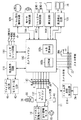
図1は、本発明の第1の実施形態を示し、ストロボカメラシステムの構成の一例を示した図である。なお、本実施形態では、1眼レフレックスカメラの場合を例に挙げて説明する。また、図1では、ストロボカメラシステムの光学的な構成を主に示している。
(First embodiment)
Next, a first embodiment of the present invention will be described with reference to the drawings.
FIG. 1 shows the first embodiment of the present invention and is a diagram showing an example of the configuration of a strobe camera system. In the present embodiment, a single lens reflex camera will be described as an example. FIG. 1 mainly shows the optical configuration of the strobe camera system.
1はカメラ本体であり、このカメラ本体1の中に光学部品、メカ部品、電気回路、フィルムなどが収納され、写真撮影が行えるようになっている。2は主ミラーであり、観察状態と撮影状態とに応じて、撮影光路へ斜設されたり、撮影光路から退去されたりする。また、主ミラー2は、ハーフミラーとなっており、斜設されているときであっても、被写体からの光線の約半分を後述する焦点検出光学系に透過させることができるように構成されている。
3は撮影レンズ12〜14の予定結像面に配置されたピント板である。4はファインダー光路変更用のペンタプリズムである。5はファインダーであり、撮影者はこのファインダー(窓)5よりピント板3を観察することで、撮影画面を観察することが出来る。
6及び7は、それぞれ、撮影画面内の被写体輝度を測定するための結像レンズと多分割測光センサである。結像レンズ6は、ペンタプリズム4内の反射光路を介してピント板3と多分割測光センサ7とを共役に関係付けている。
図4は、撮影画面上の測光エリアの一例を示す図である。撮影画面400は、23個の測光エリアA0〜A22に分割されている。多分割測光センサ7は、撮影画面400と共役に関係付けられたそれぞれの測光エリアA0〜A22の輝度を測定することが出来る。
FIG. 4 is a diagram illustrating an example of a photometric area on the photographing screen. The photographing
図1に説明を戻し、8はシャッターである。9は感光部材であり、銀塩フィルム等より成っている。
前述したように、主ミラー2は、斜設されているときであっても、被写体からの光線の約半分を透過させている。
25はサブミラーであり、被写体からの光線を下方に折り曲げて、焦点検出ユニット26の方に導く。焦点検出ユニット26内には、2次結像ミラー27、2次結像レンズ28、焦点検出ラインセンサ29等が設けられている。
Returning to FIG. 1, 8 is a shutter. A photosensitive member 9 is made of a silver salt film or the like.
As described above, the
A
本実施形態では、2次結像ミラー27と、2次結像レンズ28とにより焦点検出光学系が構成されており、これら2次結像ミラー27と、2次結像レンズ28とにより、撮影光学系の2次結像面を焦点検出ラインセンサ29上に結んでいる。焦点検出ユニット26は、後述する電気回路の処理で行われる、既知の位相差検出法により撮影画面400内の被写体の焦点状態を検出し、検出した被写体の焦点状態に基づいて、撮影レンズ12〜14の焦点調節機構を制御する。このように、本実施形態では、焦点検出ユニット26が自動焦点検出装置を実現するようにしている。
この焦点検出ユニット(自動焦点検出装置)26は、図4に示した撮影画面400内の測光エリアA0〜A6における7点の焦点状態を検出するものである。
In the present embodiment, a focus detection optical system is configured by the
The focus detection unit (automatic focus detection device) 26 detects seven focus states in the photometric areas A0 to A6 in the photographing
23は、フィルム面を測光するための測光レンズであり、24はフィルム面測光センサである。これらは、露光中にフィルム面に到達した光の拡散反射を利用して露光量を測定して、ストロボの適正光量を得る、いわゆるTTL調光に使用される。
10は、カメラと撮影レンズとのインターフェースとなるマウント接点であり、11はカメラ本体1に据え付けられるレンズ鏡筒である。12〜14は撮影レンズである。具体的に12は1群レンズであり、光軸上を左右に可動することで、撮影画面400のピント位置を調整することが出来る。13は2群レンズであり、光軸上を左右に可動することで、撮影画面400の倍率が変わり(変倍となり)、撮影レンズの焦点距離が変更される。14は3群固定レンズである。15は撮影レンズ絞りである。
16は1群レンズ駆動モータであり、自動焦点調節動作に従って1群レンズ12を左又は右に移動させることにより自動的にピント位置を調整することが出来る。17はレンズ絞り駆動モータであり、これにより撮影レンズ絞り15を開放したり、絞ったりすることが出来る。
18は外付けストロボであり、カメラ本体1に取り付けられ、カメラからの信号に従って発光制御を行うものである。なお、以下の説明では、外付けストロボ18を必要に応じて単にストロボ18と称する。
19はキセノン管であり、電流エネルギーを発光エネルギーに変換する。20、21は、それぞれ反射板とフレネルであり、それぞれ発光エネルギーを効率良く被写体に向けて集光する役目を担う。22はストロボ接点であり、カメラ本体1とストロボ18とのインターフェースとなる。
30は、グラスファイバーであり、キセノン管19の発光した光をモニタ用のセンサ(PD1)31に導いている。センサ(PD1)31は、ストロボ18のプリ発光の光量及び本発光の光量を直接測光しているものであり、本実施形態のポイントとなる、本発光量の制御のためのセンサである。
32は、キセノン管19の発光した光をモニタするセンサ(PD2)である。センサ(PD2)32の出力によりキセノン管19の発光電流が制限される。これにより、ストロボ18がフラット発光を行うことが出来る。
33は、ストロボ18がバウンス撮影になっているか否かを検知するスイッチである。
34は、反射板20を前後に移動させ、ストロボ発光の照射角を撮影レンズ12〜14の焦点距離に合わせて撮影画面400に適合させる照射角(ストロボズーム)調節機構である。
図1では、本実施形態を説明するために必要な部材の内、光学メカ部材のみ記している。これら光学メカ部材の他に、ストロボカメラシステムには電気回路部材が必要となるが、説明の都合上図1では、電気回路部材を省略している。
In FIG. 1, only the optical mechanical member is shown among members necessary for explaining the present embodiment. In addition to these optical mechanical members, an electric circuit member is required for the strobe camera system, but for convenience of explanation, the electric circuit member is omitted in FIG.
図2及び図3は、本実施形態のストロボカメラシステムの電気回路ブロックの一例を示した図である。具体的に説明すると、図2には、カメラ本体側の回路ブロックと撮影レンズ側の回路ブロックとが示してあり、図3には、ストロボ側の回路ブロックが示してある。なお、図2及び図3において、図1と対応する部材には同じ符号を付している。
まず、図2に示すカメラ本体側の回路ブロックと、撮影レンズ側の回路ブロックとから説明する。
2 and 3 are diagrams showing an example of an electric circuit block of the strobe camera system of the present embodiment. More specifically, FIG. 2 shows a circuit block on the camera body side and a circuit block on the photographing lens side, and FIG. 3 shows a circuit block on the strobe side. 2 and 3, members corresponding to those in FIG. 1 are denoted by the same reference numerals.
First, the circuit block on the camera body side and the circuit block on the photographing lens side shown in FIG. 2 will be described.
カメラマイコン100は、所定のソフトウェアによりカメラ本体1内の動作を制御する。EEPROM100bは、フィルムカウンタやその他の撮影情報を記憶可能な記憶媒体である。
A/D変換器100cは、焦点検出回路105及び測光回路106からのアナログ信号をA/D変換する。カメラマイコン100は、そのA/D変換値を信号処理することにより各種状態を設定する。
The
The A /
カメラマイコン100には、焦点検出回路105、測光回路106、シャッター制御回路107、モータ制御回路108、フィルム走行検知回路109、スイッチセンス回路110、及び液晶表示回路(LCD駆動回路)111が接続されている。また、撮影レンズ側とはマウント接点群10を介して信号の伝達がなされる。さらにストロボ側とは、ストロボ18がカメラ本体1に直接取り付けられた状態では、ストロボ接点群22を介して信号の伝達がなされる。
焦点検出ラインセンサ29は、前述したように、ファインダー5上の撮影画面400内の測光エリアA0〜A6の7点の焦点状態を検出するためのものであり、撮影光学系の2次結像面にペアで各測距点に対応して設けられたラインセンサである。
Connected to the
As described above, the focus
焦点検出回路105は、カメラマイコン100の信号に従い、これら焦点検出ラインセンサ29の蓄積制御と読み出し制御とを行って、それぞれ光電変換された画素情報をカメラマイコン100に出力する。
カメラマイコン100は、この情報をA/D変換して周知の位相差検出法による焦点検出を行う。
カメラマイコン100は、焦点検出を行うことにより得られた焦点検出情報に基づいて、撮影レンズ側に設けられたレンズマイコン112と信号のやりとり行うことにより撮影レンズ12〜14の焦点の調節を行う。
The
The camera microcomputer 100 A / D converts this information and performs focus detection by a known phase difference detection method.
The
測光回路106は、前述したように、撮影画面400内を複数の測光エリアA0〜A22に分割した多分割測光センサ7からの出力を、撮影画面400内の各測光エリアA0〜A22の輝度信号としてカメラマイコン100に出力する
As described above, the
測光回路106は、被写体に向けてストロボ光をプリ発光していない定常状態とプリ発光しているプリ発光状態との双方の状態で輝度信号をカメラマイコン100に出力する。そして、カメラマイコン100は、測光回路106から出力された輝度信号をA/D変換し、撮影時における露出を調節するための絞り値の演算と、シャッタースピードの演算と、露光時におけるストロボ18の本発光量の演算とを行う。
The
シャッター制御回路107は、カメラマイコン100からの信号に従って、シャッター先幕(MG−1)と、シャッター後幕(MG−2)とを走行させ、露出動作を行う。
モータ制御回路108は、カメラマイコン100からの信号に従ってモータを制御することにより、主ミラー2のアップダウンと、シャッター8のチャージと、フィルムの給送とを行っている。
フィルム走行検知回路109は、フィルムを給送するときに、フィルムが1駒分巻き上げられたかどうかを検知し、検知した結果をカメラマイコン100に送る。
The
The
The film running
スイッチSW1は、不図示のレリーズ釦の第1ストロークでオン(ON)するスイッチであり、測光や、AF(Auto Focus)を開始する際に撮影者により操作される。スイッチSW2は、前記レリーズ釦の第2ストロークでONするスイッチであり、露光動作を開始する際に撮影者により操作される。スイッチSWFELKは、不図示のプッシュスイッチでONするスイッチであり、露光動作の前にストロボプリ発光を行ってストロボ光量を決定し、ロックする動作を始動させる際に撮影者により操作されるスイッチである。 The switch SW1 is a switch that is turned on by a first stroke of a release button (not shown), and is operated by a photographer when starting photometry or AF (Auto Focus). The switch SW2 is a switch that is turned on by the second stroke of the release button, and is operated by the photographer when starting the exposure operation. The switch SWFELK is a switch that is turned on by a push switch (not shown), and is a switch that is operated by a photographer when starting a locking operation by determining a strobe light amount by performing strobe pre-emission before an exposure operation. .
スイッチSW1、SW2、SWFELK及びその他不図示のカメラの操作部材からの信号は、スイッチセンス回路110が検知して、カメラマイコン100に送っている。スイッチSWXは、シャッター8の全開にともなってオン(ON)するスイッチであり、ストロボ側に、露光時における本発光の発光タイミングに関わる信号を送っている。
Signals from the switches SW1, SW2, SWFELK and other camera operation members (not shown) are detected by the
液晶表示回路111は、ファインダー内LCD41の表示と、モニタ用LCD42の表示とをカメラマイコン100からの信号に従って制御している。
114は、フィルム面反射測光回路であり、フィルム面測光センサ24における測光情報をカメラマイコン100に出力する。これにより、カメラマイコン100は、フィルム面測光センサ24における測光情報を得ることが出来る。
The liquid
このフィルム面測光センサ24は、多分割測光センサ7と同様に、図4に示した撮影画面400内を分割しており、撮影画面400と共役に関係付けられたそれぞれの測光エリアA0〜A22の輝度を測定する。
The film
次に、撮影レンズの構成に関して説明を行う。カメラ本体側と撮影レンズ側とは、レンズマウント接点10を介して相互に電気的に接続される。このレンズマウント接点10は、レンズ鏡筒11内に配設されたフォーカス駆動用モータ16と絞り駆動用モータ17との電源用接点L0、レンズマイコン112の電源用接点L1、公知のシリアルデータ通信を行うためのクロック用接点L2、カメラ本体側から撮像レンズ側へのデータ送信用接点L3、撮影レンズ側からカメラ本体側へのデータ送信用接点L4、前記モータ(フォーカス駆動用モータ16と絞り駆動用モータ17)用の電源に対するモータ用グランド接点L5、及びレンズマイコン112用の電源に対するグランド接点L6を備えて構成されている。
Next, the configuration of the taking lens will be described. The camera body side and the photographing lens side are electrically connected to each other via a
レンズマイコン112は、これらのレンズマウント接点10を介してカメラマイコン100と接続され、1群レンズ駆動モータ16及びレンズ絞りモータ17を動作させ、撮影レンズ12〜14の焦点調節と絞りとを制御している。
35、36は、それぞれ光検出器とパルス板である。レンズマイコン112は、パルス数をカウントすることにより1群レンズ12の位置情報を得ることが出来る。また、レンズマイコン112は、撮影レンズ12〜14の焦点調節を行ったり、被写体の絶対距離情報をカメラマイコン100に伝達したりすることが出来る。
The
次に、図3を用いて、ストロボ18の構成に関して説明を行う。
ストロボマイコン200は、カメラマイコン100からの信号に従って、ストロボ全体の制御を行う回路である。具体的に説明すると、ストロボマイコン200は、発光量の制御や、フラット発光の発光強度及び発光時間の制御や、発光照射角の制御等を行う。
Next, the configuration of the
The
201は、DC/DCコンパータであり、ストロボマイコン(制御回路)200からの指示に従って電池(battery)の電圧を数百Vに昇圧し、メインコンデンサC1に充電する。
R1、R2は、メインコンデンサC1の電圧をストロボマイコン200が監視(モニタ)するために設けられた分圧抵抗である。ストロボマイコン200は、分圧された電圧をストロボマイコン200に内蔵されたA/D変換器によりA/D変換することにより、メインコンデンサC1の両端の電圧を間接的に監視(モニタ)する。そして、ストロボマイコン200は、監視した結果に基づいてDC/DCコンバータ201の動作を制御するにより、メインコンデンサC1の両端の電圧を所定の電圧に制御する。
A DC /
R1 and R2 are voltage dividing resistors provided for the
202はトリガ回路であり、ストロボを発光させる際に、カメラマイコン100からの指示やシャッターの先幕の走行が完了することによって発生するSWX信号により、ストロボマイコン200を介してトリガ信号を出力し、キセノン管19のトリガ電極に数千Vの高電圧を印加する。これにより、キセノン管19の放電が誘発されメインコンデンサC1に蓄えられた電荷エネルギーがキセノン管19を介して光エネルギーとして放出する。
203はIGBT等のスイッチング素子を用いた発光制御回路であり、ストロボの発光時にトリガ電極に高電圧が印加されるときには導通状態となり、キセノン管19に電流を流す。一方、ストロボの発光停止時には、発光制御回路203は、遮断状態となり、キセノン管19の電流を遮断してストロボ18の発光を停止する。
204、205はコンパレータである。コンパレータ204は、後述の閃光発光時の発光停止に用いられる。コンパレータ205は、後述のフラット発光時の発光強度制御に用いられる。206はデータセレクタであり、ストロボマイコン200の出力端子SEL0、SEL1から出力される選択信号に従い、入力端子D0〜D2の何れかを選択し、端子Yを介して発光制御回路203に信号を出力する。
207は閃光発光制御用モニタ回路であり、受光素子31の出力を対数圧縮して、増幅する。
208は、閃光発光制御用モニタ回路207の出力を積分する積分回路である。209はフラット発光制御用モニタ回路であり、受光素子32の出力を増幅する。210は前記フラット発光時間等を記憶する記憶手段であるEEPROMである。
204 and 205 are comparators. The
An
照射角(ストロボズーム)調節機構34は、モータ駆動回路(モータドライバ)211、ズーム駆動モータ212、ピニオンギア213、ラックギア214、及び反射笠20の位置を検出するズーム位置検出エンコーダ215等で構成される。
216は、ストロボが発光可能であることを示すLEDである。
The irradiation angle (strobe zoom)
スイッチSWBは、ストロボがバウンス状態であるか否かを判別するためのスイッチである。
スイッチSWTは、不図示の多灯設定釦に連動するスイッチであり、撮影者が複数のストロボを使用して撮影を行ういわゆる多灯ストロボ撮影のときに多灯設定釦を操作することによってこのスイッチSWTが連動して動作し、ストロボマイコン200が多灯ストロボの設定を行う。
The switch SWB is a switch for determining whether or not the strobe is in a bounce state.
The switch SWT is a switch that is linked to a multi-flash setting button (not shown), and this switch is operated by operating the multi-flash setting button at the time of so-called multi-flash photography where a photographer takes a picture using a plurality of flashes. The SWT operates in conjunction with the
スイッチSWMZは、不図示のマニュアルズーム設定釦の撮影者の操作に連動するスイッチである。自動で焦点距離情報を検知できないレンズを使用しているときや、撮影者が意図的に撮影画角と異なるストロボ照射角でストロボを照射し、被写体にスポット的にストロボを照射するなどの特殊効果を狙った撮影を行うときに、マニュアルズーム設定釦を撮影者が操作することによってこのスイッチSWMZが連動して動作する。そして、ストロボマイコン200が照射角調節機構34を動作させ、撮影者の設定したい照射角の設定を行う。
The switch SWMZ is a switch that is linked to the operation of the photographer on a manual zoom setting button (not shown). Special effects such as when using a lens that cannot automatically detect focal length information, or when the photographer intentionally shoots a strobe with a strobe angle different from the shooting angle of view and irradiates the subject with a spot. The switch SWMZ operates in conjunction with the manual zoom setting button when the user operates the manual zoom setting button. The
次に、ストロボマイコン200の各端子の説明を行う。
CKは、カメラ本体1とのシリアル通信を行う為の同期クロックの入力端子である。DIは、前記シリアル通信で行われるデータの入力端子である。DOは、前記シリアル通信で行われるデータの出力端子である。CHGは、ストロボ18の発光可能状態を電流としてカメラ本体1に伝えるための出力端子である。Xは、カメラ本体1からの発光タイミング信号であるSWX信号の入力端子である。
Next, each terminal of the
CK is an input terminal of a synchronous clock for performing serial communication with the
ECKは、ストロボマイコン200の外部に接続された記憶手段であるEEPROMもしくはフラッシュROM等の書込可能な記憶手段210とシリアル通信を行うための通信クロックを出力するための出力端子である。EDIは、前記記憶手段210からのシリアルデータの入力端子である。EDOは、前記記憶手段210へのシリアルデータの出力端子である。SELEは、前記記憶手段210との通信を許可する際に使用されるイネーブル端子であり、説明の都合上、Loでイネーブル、Hiでディスエーブルとする。なお、本実施形態では、ストロボマイコン200の外部に記憶手段210を設定したが、記憶手段210に相当する機能がストロボマイコン200に内蔵されていてもよいということは言うまでもない。
ECK is an output terminal for outputting a communication clock for serial communication with writable storage means 210 such as EEPROM or flash ROM which is storage means connected to the outside of the
POWはパワースイッチ217の状態を入力するための入力端子である。OFFは、パワースイッチ217と接続されたときにストロボ18をオフ状態にするための出力端子である。ONは、パワースイッチ217と接続されたときのストロボ18をオン状態にするための出力端子である。パワースイッチ217がオン(ON)の状態ではPOW端子はON端子と接続される。この場合、ON端子はハイインピーダンス状態であり、OFF端子はローインピーダンス状態である。一方、パワースイッチ217がオフ(OFF)の状態では、その逆であり、ON端子はローインピーダンス状態であり、OFF端子はハイインピーダンス状態である。LEDは発光可能を表示するLED216の表示出力端子である。
POW is an input terminal for inputting the state of the
STOPは、発光停止信号の入力端子であり、説明の都合上、Loで発光停止状態とする。SEL0、SEL1は、前記データセレクタ206の入力選択を指示するための出力端子であり、出力端子SEL0、SEL1から出力される選択信号の組み合わせが、(SEL1、SEL0)=(0、0)のときは入力端子D0が端子Yに接続される。同様に、出力端子SEL0、SEL1から出力される選択信号の組み合わせが(SEL1、SEL0)=(0、1)のときは端子D1が選択される。そして、出力端子SEL0、SEL1から出力される選択信号の組み合わせが(SEL1、SEL0)=(1、0)のときは入力端子D2が選択される。
STOP is an input terminal for a light emission stop signal. For convenience of explanation, the light emission stop state is set to Lo. SEL0 and SEL1 are output terminals for instructing the input selection of the
DA0は、ストロボマイコン200に内蔵されたD/A出力端子であり、コンパレータ204、205のコンパレートレベルをアナログ電圧で出力するための端子である。TRIGは、トリガ回路202に発光を指示するトリガ信号出力端子である。CNTは、DC/DCコンバータ201の発振開始停止を制御する出力端子であり、説明の都合上、Hiで充電開始、Loで充電停止とする。INTは、積分回路208の積分の開始/リセットを制御する積分開始端子であり、説明の都合上、Hiで積分リセット、Loで積分許可とする。
DA0 is a D / A output terminal built in the
AD0、AD1は、A/D入力端子であり、ストロボマイコン200の内部で処理できるようにすべく、入力される電圧をディジタルデータに変換できるようにするためのものである。具体的に説明すると、A/D入力端子AD0は、メインコンデンサC1の電圧を監視(モニタ)することができるようにするためのものであり、A/D入力端子AD1は、積分回路208の積分出力電圧を監視(モニタ)することができるようにするためのものである。
AD0 and AD1 are A / D input terminals for enabling the input voltage to be converted into digital data so that it can be processed inside the
Z0、Z1は、ズーム駆動モータ212を駆動するモータ制御回路211を制御することができるようにするための制御出力端子である。ZM0、ZM1、ZM2は、ズーム位置検出エンコーダ215からの信号を入力する入力端子である。COM0は、ズーム位置検出エンコーダ215のグランドレベルに相当する電流引き込みを行う共通端子である。
Z0 and Z1 are control output terminals for enabling the
BOUNCEは、ストロボがバウンス状態であるか否かを示す信号を入力する端子(ポート)である。TATOUは、前述した多灯ストロボを設定するためのスイッチの設定状態を入力する端子(ポート)である。M_Zoomは、マニュアルズームの設定スイッチの設定状態を入力する端子(ポート)である。 BOUNCE is a terminal (port) for inputting a signal indicating whether or not the strobe is in a bounce state. TATOU is a terminal (port) for inputting a setting state of a switch for setting the above-described multi-flash. M_Zoom is a terminal (port) for inputting the setting state of the manual zoom setting switch.
次に、このストロボのそれぞれの動作を説明しながら、回路の動作を説明する。
<発光可能状態検知>
ストロボマイコン200は、メインコンデンサC1の分圧された電圧を、A/D入力端子AD0を介して入力する。そして、入力した電圧をA/D変換することによって、メインコンデンサC1の電圧が発光可能な所定の電圧以上であると判別すると、出力端子CHGより所定の電流を吸い込み、カメラ本体1に発光可能であることを伝える。また、ストロボマイコン200は、端子LEDをHiに設定し、LED216を発光させて、ストロボが発光可能であることを表示する。
Next, the operation of the circuit will be described while explaining the operation of each strobe.
<Light emission enabled state detection>
The
一方、ストロボマイコン200は、メインコンデンサC1の電圧が所定の電圧以下であると判別した場合には、出力端子CHGをノンアクティブに設定して電流を遮断する。これにより、カメラ本体1には、ストロボ18が発光不能であることが伝わる。また、ストロボマイコン200は、端子LEDをLoに設定して、LED216を消灯させて、ストロボが発光不能であることを表示する。
On the other hand, when it is determined that the voltage of the main capacitor C1 is equal to or lower than the predetermined voltage, the
<ストロボ照射角設定>
ストロボマイコン200は、入力端子ZM0〜ZM2から現在のズーム位置を読み込み、シリアル通信によってカメラ本体1から指示されたズーム位置になるように、制御出力端子Z0、Z1を介して所定の信号をモータ駆動回路211に出力することによりモータ駆動回路211を駆動する。
また、不図示のマニュアルズーム設定釦によって撮影者がマニュアルでストロボ照射角を設定するときには、ストロボマイコン200は、端子M_Zoomから入力される信号に従って所定のズーム位置になるようにモータ駆動回路211を駆動する。
<Flash exposure angle setting>
The
When the photographer manually sets the flash illumination angle using a manual zoom setting button (not shown), the
<予備フラット発光>
ストロボが発光可能な状態のとき、カメラ本体1は、プリ発光の発光強度と発光時間とを通信すると共に、プリ発光を指示することができる。
ストロボマイコン200は、カメラ本体1より指示された所定の発光強度信号に応じて、D/A出力端子DA0に所定の電圧を設定する。次に、出力端子SEL1、SEL0に対してそれぞれLo、Hiを出力し、端子D1を選択する。このとき、キセノン管19はまだ発光していないので、受光素子32の光電流はほとんど流れず、コンパレータ205の反転入力端子には、モニタ回路209の出力は発生しない。また、コンパレータ205の出力はHiであるので、発光制御回路203は導通状態となる。次に、トリガ信号出力端子TRIGよりトリガ信号が出力されると、トリガ回路202は高電圧を発生してキセノン管19を励起させ、発光を開始させる。
<Preliminary flat light emission>
When the strobe is capable of emitting light, the
The
一方、ストロボマイコン200は、トリガ信号の発生から所定時間が経過した後、積分回路208に積分開始を指示する。これにより、積分回路208は、モニタ回路207の出力、すなわち、光量積分用の受光素子31の対数圧縮された光電出力を積分開始すると同時に、所定時間をカウントするタイマを起動させる。
On the other hand, the
プリ発光が開始されると、フラット発光の発光強度制御用受光素子32の光電流が多くなり、モニタ回路209の出力が上昇する。こうして、モニタ回路209の出力電圧が、コンパレータ205の非反転入力に設定されている所定のコンパレート電圧より高くなると、コンパレータ205の出力はLoに反転する。そうすると、発光制御回路203はキセノン管19の発光電流を遮断し、放電ループが絶たれるが、ダイオードD1、コイルL1により環流ループが形成され、回路の遅れによるオーバーシュートが収まった後は、発光電流は徐々に減少する。発光電流の減少に伴い、発光強度が低下するので、受光素子32に流れる電流は減少して、モニタ回路209の出力は低下する。こうして、モニタ回路209の出力電圧が、所定のコンパレートレベル以下に低下すると、コンパレータ205の出力は再びHiに反転する。そうすると、発光制御回路203が再度導通し、キセノン管19の放電ループが形成され、発光電流が増加して発光強度も増加する。このように、D/A出力端子DA0に設定された所定のコンパレート電圧を中心に、コンパレータ205は短い周期で発光強度の増加と減少とを繰り返し結果的には、所望するほぼ一定の発光強度で発光を継続させるフラット発光の制御が出来る。
When pre-emission is started, the photocurrent of the light emission intensity control
前述した発光時間タイマをカウントし、所定のプリ発光時間が経過すると、ストロボマイコン200は、出力端子SEL1、SEL0をLo、Loに設定する。そうすると、データセレクタ206の入力は、入力端子D0、すなわちLoレベルの入力が選択される。これにより、データセレクタ206の出力は強制的にLoレベルとなり、発光制御回路203はキセノン管19の放電ループを遮断し、ストロボ18の発光を終了させる。
When the above-described light emission time timer is counted and a predetermined pre-light emission time has elapsed, the
ストロボ18の発光を終了させたときに、ストロボマイコン200は、プリ発光を積分した積分回路208の出力をA/D入力端子AD1から読み込んでA/D変換し、積分値、すなわちプリ発光時の発光量をディジタル値(INTp)として読みとることができる。
When the light emission from the
<本発光制御>
カメラマイコン100は、プリ発光時の多分割測光センサ7からの被写体反射光輝度値等から、本発光時における発光量のプリ発光に対する適正相対値(γ)を求め、ストロボマイコン200に送る。
ストロボマイコン200は、プリ発光時の測光積分値(INTp)にカメラ本体1からの適正相対値(γ)の値を掛け合わせて適正積分値(INTm)を求め、D/A出力端子DA0に適正積分値(INTm)を設定する。
<Main flash control>
The
The
次に、出力端子SEL1、SEL0に、それぞれハイレベルの信号Hiと、ローレベルの信号Loとを出力して、端子D2を選択する。このとき、積分回路208は、動作禁止状態なので、コンパレータ204の反転入力端子に積分回路208の出力は発生しない。また、コンパレータ204の出力はハイレベル(Hi)であるので、発光制御回路203は導通状態となる。
Next, a high level signal Hi and a low level signal Lo are output to the output terminals SEL1 and SEL0, respectively, and the terminal D2 is selected. At this time, since the
次に、トリガ信号出力端子TRIGよりトリガ信号が出力されると、トリガ回路202は、高電圧を発生してキセノン管19を励起させる。これによりストロボ18の発光が開始される。また、ストロボマイコン200は、トリガ信号の印加によるトリガノイズが収まるとともに、実際の発光が開始されてから十数μsecが経過した後に、積分開始端子INTをローレベル(Lo)に設定する。そうすると、積分回路208は、センサ31からの出力を、モニタ回路207を介して積分する。積分出力が、D/A出力端子DAOに設定された所定電圧に到達すると、コンパレータ204は、反転し、データセレクタ206を介して発光制御回路203は導通が遮断される。これにより、ストロボ18の発光は停止する。一方、ストロボマイコン200は、STOP端子をモニタし、入力端子STOPの信号レベルが反転してストロボ18の発光が停止すると、出力端子SEL1、SEL0をLo、Lo((0,0))に設定し、強制的に発光禁止状態に設定するとともに、積分開始端子INTを反転し、積分を終了し、発光処理を終了する。
このようにして、本発光を適正な発光量に制御することが出来る。
Next, when a trigger signal is output from the trigger signal output terminal TRIG, the
In this way, the main light emission can be controlled to an appropriate light emission amount.
次に、図6〜図7を用いて、本実施形態のストロボカメラシステムの動作の一例をカメラマイコン100の動作を中心に説明する。
Next, an example of the operation of the strobe camera system according to the present embodiment will be described focusing on the operation of the
[ステップS101]
図6においてカメラの動作が開始すると、カメラマイコン100は、まずレリーズ釦の第1のストロークでオン(ON)するスイッチSW1がオン(ON)であるかどうかを判別する。スイッチSW1がオンになるまではこの動作を繰り返し、スイッチSW1がオンになると次のステップS102に移行する。
[Step S101]
In FIG. 6, when the operation of the camera is started, the
[ステップS102]
カメラマイコン100は、前述した測光回路106より、撮像画面400内の複数の測光エリアA0〜A22における被写体輝度情報をA/D変換により得る。
この被写体輝度情報により、後述する露光動作に用いるシャッタースピードや、絞り値が演算により求められる。
[Step S102]
The
Based on the subject luminance information, a shutter speed and an aperture value used for an exposure operation described later are obtained by calculation.
[ステップS103]
カメラマイコン100は、焦点検出回路105を駆動することにより、周知の位相差検出法による焦点検出動作を行う。
焦点検出するポイント(測距ポイント)は、前述したように複数ある。このため、焦点検出動作としては、撮影者が任意に測距ポイントを設定できる方式や、近点優先を基本の考え方とした周知の自動選択アルゴリズムを用いた方式などを採用することができる。
[Step S103]
The
As described above, there are a plurality of points (ranging points) for focus detection. For this reason, as a focus detection operation, a method in which the photographer can arbitrarily set a distance measuring point, a method using a known automatic selection algorithm based on near point priority, or the like can be adopted.
[ステップS104]
カメラマイコン100は、選択された測距ポイントが合焦となるように、撮影レンズ側と通信を行うことによって撮影レンズ12〜14の焦点調節を行う。
なお、カメラマイコン100は、撮影レンズ12〜14の合焦位置の絶対距離情報を、撮像レンズ側と通信することによって得ることが出来る。
[Step S104]
The
The
[ステップS105]
カメラマイコン100は、レリーズ釦の第2のストロークでオン(ON)するスイッチSW2がオン(ON)であるかどうかを判別する。この判別の結果、スイッチSW2がオフ(OFF)であれば、ステップS101〜S104の動作を繰り返す。一方、スイッチSW2がオン(ON)であれば、ステップS106以下のレリーズ動作に進む。
[ステップS106]
レリーズ動作に入るとまず、ストロボの発光量を演算するためのサブルーチンをコールする。
[Step S105]
The
[Step S106]
When the release operation is started, a subroutine for calculating the flash emission amount is first called.
ここで図7を用い、ストロボの発光量を演算する際の処理の一例を詳細に説明する。
[ステップS201]
カメラマイコン100は、プリ発光の直前に被写体輝度情報を測光回路106により得る。その輝度値P(i)(i=0〜22)は、それぞれの測光エリアA0〜A22毎にRAMに記憶される。この輝度値P(i)は、対数圧縮(log圧縮)された値であり、輝度が2倍になると、1増加するといった値である。
Here, with reference to FIG. 7, an example of processing when calculating the light emission amount of the strobe will be described in detail.
[Step S201]
The
[ステップS202]
カメラマイコン100は、ストロボ側に対してプリ発光の命令を行う。ストロボマイコン200はこの命令に従って、前述したようにプリ発光動作を行う。
カメラマイコン100は、プリ発光のフラット発光が持続している間に被写体輝度情報を測光回路106により得る。その輝度値H(i)(i=0〜22)は、それぞれの測光エリアA0〜A22毎に、RAMに記憶される。この輝度値H(i)も対数圧縮(log圧縮)された値である。
[Step S202]
The
The
[ステップS203]
カメラマイコン100は、プリ発光の直前の輝度値P(i)と、プリ発光時の輝度値H(i)とから、プリ発光時の反射光分のみの輝度値D(i)を抽出する。具体的には、以下の(1式)を用いて輝度値D(i)を演算し、演算した輝度値D(i)をRAMに記憶させる。
D(i)=log2(2H(i)−2P(i));i=0〜22・・・(1式)
[Step S203]
The
D (i) = log 2 (2 H (i) −2 P (i) ); i = 0 to 22 (1 formula)
ここでは、プリ発光の直前の輝度値P(i)と、プリ発光時の輝度値H(i)とがそれぞれ圧縮系の値である。このため、輝度値P(i)、H(i)のべき乗をとって伸長させてから差分をとり、この差分した値を対数圧縮(log圧縮)して輝度値D(i)を算出している。 Here, the luminance value P (i) immediately before the pre-emission and the luminance value H (i) at the time of the pre-emission are values of the compression system. For this reason, the luminance values P (i) and H (i) are exponentiated and expanded to obtain a difference, and the difference value is logarithmically compressed (log compression) to calculate the luminance value D (i). Yes.
[ステップS204]
カメラマイコン100は、プリ発光する前とプリ発光したときとの各測光エリアA0〜A23における輝度値の比R(i)を演算する。具体的には、以下の(2式)を用いて、輝度値の比R(i)を演算し、演算した輝度値の比R(i)をRAMに記憶させる。
R(i)=H(i)−P(i);i=0〜22・・・(2式)
ここでは、プリ発光の直前の輝度値P(i)と、プリ発光時の輝度値H(i)とがそれぞれ圧縮系の値であるため、これら輝度値の差分をとることは、輝度値の比をとることと等価である。
[Step S204]
The
R (i) = H (i) -P (i); i = 0 to 22 (Expression 2)
Here, since the luminance value P (i) immediately before the pre-emission and the luminance value H (i) at the time of the pre-emission are values of the compression system, the difference between these luminance values is the luminance value. It is equivalent to taking a ratio.
ここで、なぜ比をとるかというと、プリ発光のないときに撮像画面400内の各測光エリアA0〜A22の被写体が、その雰囲気中の何がしかの光源に一様に照らされていると仮定すると、各測光エリアA0〜A22の輝度は、被写体の反射率に比例する。ここでプリ発光を行うと、被写体の反射光は距離のマイナス2乗に比例し、被写体の反射率にも比例する。つまり、プリ発光する前とプリ発光したときのそれぞれにおいて、各測光エリアA0〜A22の輝度値の比を演算すると、被写体の距離のマイナス2乗に比例した値を求めることとなる。よって、輝度値の比R(i)の値が同一の測光エリアA0〜A22は、被写体までの距離が同一であるといえる。このように、同一の距離の測光エリアA0〜A22が、撮像画面400内にどういう分布となっているのかが、本実施形態のポイントとなっている。
[ステップS205]
カメラマイコン100は、被写体の距離に関する情報から所定値LVL0、LVL1の演算を行う。具体的に所定値LVL0は、以下の(3式)を用いて演算される。
LVL0=−Log2(D)×2+C2・・・(3式)
Here, the reason why the ratio is taken is that the subjects in the photometric areas A0 to A22 in the
[Step S205]
The
LVL0 = −Log 2 (D) × 2 + C2 (3 formulas)
この所定値LVL0は、前述したようにレンズマイコン112より、被写体の絶対距離情報Dを得て、その距離における標準的な反射率の被写体の場合の反射輝度がどの程度になるかを考慮して計算される。前記(3式)において、C2は、プリ発光の発光量等で決まる値であり、距離情報Dでの標準的な反射率の被写体の場合の反射輝度より、所定値LVL0が少し高くなるように決められる。これは、距離情報Dが多少の誤差や幅をもっているため、その誤差分だけ高くして、実際の標準的な反射率の被写体のプリ発光時における反射光が、所定値LVL0より高くならないようにするためである。なお、所定値LVL0も圧縮系の値である。
As described above, the predetermined value LVL0 is obtained by obtaining the absolute distance information D of the subject from the
一方、所定値LVL1は、以下の(4式)を用いて演算される。
LVL1=LVL0−C3・・・(4式)
前記(4式)において、C3は、実際の標準的な反射率の被写体のプリ発光時における反射光が、所定値LVL1より下回らないように、距離情報Dの誤差や幅を考慮して決められている。なお、所定値LVL1も圧縮系の値である。
On the other hand, the predetermined value LVL1 is calculated using the following (Equation 4).
LVL1 = LVL0-C3 (4 formulas)
In the above (Formula 4), C3 is determined in consideration of the error and width of the distance information D so that the reflected light at the time of pre-emission of the subject having the actual standard reflectance does not fall below the predetermined value LVL1. ing. The predetermined value LVL1 is also a value of the compression system.
このように、距離情報Dから、被写体のプリ発光時における反射光が所定値LVL0〜LVL1の間にあるはずであるという前提で、以下のストロボの本発光時における発光量の演算を行う。なお、距離情報Dが非常に正確であれば、このような幅を設けることなく、距離情報Dからフラッシュマティック的にストロボ18の本発光時における発光量を決めてもよい。
しかしながら、実際には被写体の距離情報Dには誤差や幅(距離の分解能)があるため、以下のような演算が必要になる。
As described above, from the distance information D, on the premise that the reflected light at the time of pre-emission of the subject should be between the predetermined values LVL0 to LVL1, the light emission amount at the time of the main flash emission is calculated. If the distance information D is very accurate, the amount of light emitted during the main light emission of the
However, since the subject distance information D actually has an error and a width (distance resolution), the following calculation is required.
また、被写体の絶対距離情報が不明なシステムでは、所定値LVL0は、以下の(5式)のように表される。
LVL0=table1(f)・・・(5式)
前記(5式)において、fは、焦点距離である。なお、table1は、図9に示すテーブル900を意味する。
Further, in a system in which the absolute distance information of the subject is unknown, the predetermined value LVL0 is expressed as (Formula 5) below.
LVL0 = table1 (f) (Expression 5)
In the above (Formula 5), f is a focal length. Note that table1 means the table 900 shown in FIG.
例えば、焦点距離が28mmの撮影レンズであれば、0.5mの距離に標準的な反射率の被写体があった場合の反射輝度をLVL0とするのである。これは、この焦点距離で撮影をする場合、0.5mよりも近い被写体を撮影することはまずありえないので、被写体のプリ発光時の反射光が、所定値LVL0よりも低いはずであるということに基づくものである。同じく、焦点距離が50mmの撮影レンズであれば0.8mの距離に標準的な反射率の被写体があった場合の反射輝度をLVL0とする。さらに、焦点距離が85mmの撮影レンズであれば、1.1mの距離に標準的な反射率の被写体があった場合の反射輝度をLVL0とする。すなわち、これらの距離よりも被写体は遠くにあるはずで、被写体のプリ発光時における反射光が所定値LVL0よりも低いはずだということになる。 For example, in the case of a photographic lens with a focal length of 28 mm, the reflection luminance when a subject with a standard reflectance is 0.5 m away is set to LVL0. This is because, when shooting at this focal length, it is unlikely that a subject closer than 0.5 m will be shot, so the reflected light at the time of pre-emission of the subject should be lower than the predetermined value LVL0. Is based. Similarly, if the photographing lens has a focal length of 50 mm, the reflection luminance when a subject having a standard reflectance is located at a distance of 0.8 m is LVL0. Further, in the case of an imaging lens with a focal length of 85 mm, the reflection luminance when a subject having a standard reflectance is 1.1 m away is LVL0. That is, the subject should be farther than these distances, and the reflected light at the time of pre-emission of the subject should be lower than the predetermined value LVL0.
一方、被写体の絶対距離情報が不明なシステムでは、所定値LVL1は、以下の(6式)のように表される。
LVL1=LVL0−C1・・・(6式)
前記(6式)において、C1は、被写体が所定値LVL1より下回ることは、あまりないということに基づいて決められており、例えば、焦点距離が50mmの撮影レンズである場合、3.2mより遠くに被写体があるという確率が少ないということであれば、8倍(6.4÷0.8=8)の距離のときは、被写体からの反射光が6段低くなるので、C1は6になる。
[ステップS206]
カメラマイコン100は、各測光エリアA0〜A22における輝度値D(i)が、前述した所定値LVL0〜LVL1の間に入る領域だけを抜き出す
これにより、ガラスからの正反射により、輝度値D(i)が非常に高くなっている測光エリアA0〜A22や、ストロボ光が完全に届かなくて、輝度値D(i)が非常に低くなっている測光エリアA0〜A22を除外し、主被写体が存在していそうな測光エリアA0〜A22だけを抜き出す。
なお、プリ発光時の輝度値H(i)の値は、輝度値D(i)の値と大きく変わらないことが多いので(プリ発光の直前の輝度値P(i)が小さい場合が多いので)、この部分ではプリ発光時の輝度値H(i)を使用してもよい。
On the other hand, in a system in which the absolute distance information of the subject is unknown, the predetermined value LVL1 is expressed as (Expression 6) below.
LVL1 = LVL0-C1 (Expression 6)
In (Expression 6), C1 is determined based on the fact that the subject is not much less than the predetermined value LVL1, and is, for example, farther than 3.2 m when the photographing lens has a focal length of 50 mm. If there is a low probability that there is a subject, the reflected light from the subject is reduced by 6 steps at a distance of 8 times (6.4 ÷ 0.8 = 8), so C1 becomes 6. .
[Step S206]
The
Note that the value of the luminance value H (i) at the time of pre-emission is not much different from the value of the luminance value D (i) (because the luminance value P (i) immediately before the pre-emission is often small). ), The luminance value H (i) at the time of pre-emission may be used in this portion.
[ステップS207]
前記のようにして抜き出した測光エリアA0〜A22の中で、一番近くにいる被写体が主被写体である確率が一番高いので、前述したプリ発光の直前の輝度値P(i)と、プリ発光時の輝度値H(i)との比R(i)が最大のものを、基準値baseRとし、この輝度値の比R(i)が基準値baseRと同一の被写体を主被写体と仮定する。
[Step S207]
Of the photometric areas A0 to A22 extracted as described above, the probability that the closest subject is the main subject is the highest. Therefore, the luminance value P (i) immediately before the pre-flash and the pre-flash are calculated. The reference value baseR is the one having the largest ratio R (i) to the luminance value H (i) at the time of light emission, and the subject whose luminance value ratio R (i) is the same as the reference value baseR is assumed as the main subject. .
[ステップS208]
カメラマイコン100は、各測光エリアA0〜A22において、輝度値の比R(i)と基準値baseRとの差RR(i)を求める。具体的には、以下の(7式)を用いて求める。
RR(i)=baseR−R(i);i=0〜21・・・(7式)
[Step S208]
The
RR (i) = baseR-R (i); i = 0 to 21 (Expression 7)
基準値baseRと輝度値の比R(i)は、共に圧縮系の値であるので、実際には基準の距離の測光エリア(基準値baseRとなる測光エリア)の輝度値と、その他の測光エリアの輝度値との比を、この前記(7式)で求めることになる。この値RR(i)が小さい測光エリアは、仮定した主被写体と等価な距離に被写体があるエリアである。これに対し、この値RR(i)が正に大きくなる測光エリアほど、被写体は、仮定した主被写体よりも遠くに離れていることになる。逆に、この値RR(i)が負に大きくなる測光エリアほど、被写体は、仮定した主被写体よりも近くにあることになる。すなわち、この場合は、被写体が障害物であったり、ガラスからの正反射があったりしたために、前記(7式)で得られる値RR(i)が異常な値を示していることになる。 Since the ratio R (i) between the reference value baseR and the luminance value is a compression system value, the luminance value of the photometric area at the standard distance (the photometric area that becomes the standard value baseR) and other photometric areas are actually used. The ratio with the luminance value is obtained by the above (Expression 7). The photometric area where this value RR (i) is small is an area where the subject is at a distance equivalent to the assumed main subject. On the other hand, in the photometric area where the value RR (i) is positively increased, the subject is farther away than the assumed main subject. Conversely, the photometric area where the value RR (i) is negatively increased, the closer the subject is to the assumed main subject. That is, in this case, the value RR (i) obtained by the above (Expression 7) shows an abnormal value because the subject is an obstacle or has regular reflection from the glass.
[ステップS209]
前記(7式)で得られる値RR(i)より、各測光エリアA0〜A22における重み付け係数W(i)を求める。具体的には、以下の(8式)を用いて重み付け係数W(i)を求める。
W(i)=table2(RR(i));i=0〜22・・・(8式)
[Step S209]
The weighting coefficient W (i) in each photometric area A0 to A22 is obtained from the value RR (i) obtained in (Expression 7). Specifically, the weighting coefficient W (i) is obtained using the following (Equation 8).
W (i) = table2 (RR (i)); i = 0 to 22 (Expression 8)
前記(8式)において、table2は、図10に示すテーブル1000を意味している。図10に示すテーブル1000において、まず、RR(i)が0のところをみると、重み付け係数W(i)は、12となっていて、一番重み付け係数が高い。これは、RR(i)が0の測光エリアが、主被写体と仮定した領域であるので当然のことである。一方、RR(i)が、0.4、0.6、・・・、2.0とだんだん大きくなっていくと、これは主被写体と仮定した領域からだんだん遠くなっていく領域であるので、重み付け係数W(i)は、11、10、・・・、0とだんだんと小さくなるようにしている。このように、重み付け係数W(i)が徐々に小さくなるようにすれば、撮影毎に被写体が移動してキリムラ(ストロボ露出がばらつくこと)になることを可及的に防止することができる。また、奥行きのある被写体であれば、一番近くにある被写体だけに重み付けをかけるよりも、奥行きのあるところにも重み付けをかけて、平均化したほうが、奥までストロボ光が周り、よい写真にすることができる。 In the equation (8), table2 means the table 1000 shown in FIG. In the table 1000 shown in FIG. 10, first, when RR (i) is 0, the weighting coefficient W (i) is 12, which is the highest weighting coefficient. This is natural because the photometric area where RR (i) is 0 is an area assumed to be the main subject. On the other hand, as RR (i) gradually increases to 0.4, 0.6,..., 2.0, this is a region that is gradually distant from the region assumed as the main subject. The weighting coefficient W (i) is gradually reduced to 11, 10,. In this way, if the weighting coefficient W (i) is gradually reduced, it is possible to prevent as much as possible that the subject moves and becomes kilimra (the flash exposure varies) at every photographing. Also, if the subject is deep, it is better to apply weighting to the depth and to average it, rather than weighting only the closest subject. can do.
RR(i)がマイナスになる領域は、障害物であったり、ガラスからの正反射であったりするために異常な値を示したものであるため、重み付け係数W(i)の値を小さくすする。ただし、前記キリムラを避けるために、急激に重み付けを小さくすることはしていない。
ここで、注意すべきことは、ステップS206では、主被写体の存在しそうな測光エリア以外の測光エリアは演算の対象から除外しているが、ステップS209で重み付け係数W(i)を決定する測光エリアは、撮影画面400内の全ての測光エリアA0〜A22であることである。
The region where RR (i) is negative indicates an abnormal value due to an obstacle or regular reflection from the glass, so the value of the weighting coefficient W (i) is reduced. To do. However, in order to avoid the above-mentioned Kilimra, the weight is not reduced rapidly.
Here, it should be noted that in step S206, a photometric area other than the photometric area where the main subject is likely to exist is excluded from the calculation target, but in step S209, the photometric area in which the weighting coefficient W (i) is determined. Is all the photometric areas A0 to A22 in the photographing
[ステップS210]
被写体の反射光の重み付け平均の演算を行う。具体的には、以下の(8式)を用いて行う。
[Step S210]
The weighted average of the reflected light of the subject is calculated. Specifically, the following (Equation 8) is used.

この重み付け演算により、カメラから同一の距離にある測光エリアで主被写体をうまく抽出して、主被写体に大きく重み付けをかけることにより、被写体からの反射光の演算が出来る。 By this weighting calculation, the main subject is well extracted in the photometry area at the same distance from the camera, and the main subject is heavily weighted, whereby the reflected light from the subject can be calculated.
[ステップS211]
本発光の発光量を演算する。
γ=TARGET−AVE・・・(9式)
TARGETは、フィルム面に適正な露光を得るためのターゲットの光量である。また、γは、プリ発光時における発光量に対する本発光時における発光量の適正相対値である。なお、この相対値γは、カメラマイコン100からストロボマイコン200へ送られるものである。
[ステップS107]
図6に説明を戻し、カメラマイコン100は、露光動作を行う。
すなわち、主ミラー2をアップさせて、主ミラー2をサブミラー25とともに撮影光路より退去させる。そして、撮影レンズ12〜14を制御して絞りを制御し、決められたシャッタースピード値(TV)になるようにシャッター制御回路107を制御する。
このとき、シャッターの全開に同期させてスイッチSWXをオン(ON)する。これにより、露光時における本発光の発光タイミングに関わる信号がストロボ側に伝わる。すなわち、ストロボ側では、この発光タイミングに関わる信号により本発光の命令を受ける。
[Step S211]
The amount of main light emission is calculated.
γ = TARGET-AVE (9 formulas)
TARGET is the light amount of the target for obtaining appropriate exposure on the film surface. Further, γ is an appropriate relative value of the light emission amount during main light emission with respect to the light emission amount during pre-light emission. The relative value γ is sent from the
[Step S107]
Returning to FIG. 6, the
That is, the
At this time, the switch SWX is turned on in synchronization with the shutter fully opened. Thereby, a signal related to the light emission timing of the main light emission at the time of exposure is transmitted to the strobe side. That is, the strobe side receives a main light emission command by a signal related to the light emission timing.
ストロボマイコン200は、カメラから送られてきた補正値γに基づいて、適正な発光量となるように、前述したような本発光の制御を行う。
最後に、撮影光路より退去された主ミラー2等をダウンし、再び撮影光路へ斜設させ、モータ制御回路108とフィルム走行検知回路109とにより、フィルムを1駒巻き上げる。
The
Finally, the
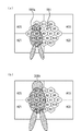
本実施形態の効果を図5を用いて説明する。
図5(a)の撮影シーンでは、主被写体500aは、測光エリアA15、A14、A4に存在し、ガラス501からの正反射が測光エリアA2に存在する。
前述した図7のステップS205、S206において、測光エリアA2におけるD(i)(プリ発光時の反射光分のみの輝度値)が、所定値LVL0よりも大きいので、測光エリアA2は、主被写体として抽出するエリアの候補から除外される。次に、ステップS207において、基準値baseRは、測光エリアA15におけるR(i)(プリ発光の直前の輝度値P(i)とプリ発光時の輝度値H(i)との比)となる。また、測光エリアA15、A14、A5におけるRR(i)(R(i)とbaseRとの差)がほぼ0となる。したがって、これら3つの測光エリアA15、A14、A5を中心に重み付けがなされ、被写体からの反射光が演算される。よって、この主被写体500aを適正にストロボの光量を制御することが可能である。
The effect of this embodiment will be described with reference to FIG.
5A, the
In steps S205 and S206 of FIG. 7 described above, D (i) in the photometric area A2 (the luminance value of only the reflected light during pre-emission) is greater than the predetermined value LVL0, so that the photometric area A2 is the main subject. Excluded from extraction area candidates. Next, in step S207, the reference value baseR is R (i) (ratio of the luminance value P (i) immediately before the pre-light emission and the luminance value H (i) at the time of the pre-light emission) in the photometry area A15. Further, RR (i) (difference between R (i) and baseR) in the photometric areas A15, A14, and A5 is substantially zero. Therefore, weighting is performed around these three photometric areas A15, A14, and A5, and the reflected light from the subject is calculated. Therefore, it is possible to appropriately control the light quantity of the strobe of the
図5(b)の撮影シーンでは、主被写体500bは、測光エリアA3、A4、A5、A11、A12、A14、A15に存在する。この撮影シーンでは、測光エリアA3、A4、A5、A11、A12、A14、A15におけるRR(i)がほぼ0となって、これら7つの測光エリアを中心に重み付けがなされ、被写体からの反射光が演算される。よって、この主被写体500bを適正にストロボの光量を制御することが可能である。
In the shooting scene of FIG. 5B, the
このように本実施形態では、撮影画面400内における被写体の位置や大きさに影響を受けずに、主被写体を抽出して、重み付け平均の演算を行うので、可及的に信頼性の高いストロボ発光量の制御が可能になる。
As described above, in the present embodiment, the main subject is extracted and the weighted average is calculated without being affected by the position and size of the subject in the
(第2の実施形態)
次に、本発明の第2の実施形態について説明する。なお、本実施形態は、前述した第1の実施形態とストロボからの発光量を演算する際の処理の一部が異なるだけである。したがって、前述した第1の実施形態と同一の部分については、図1〜図10に付した符号を付すなどして詳細な説明を省略する。
(Second Embodiment)
Next, a second embodiment of the present invention will be described. Note that this embodiment is different from the first embodiment described above only in part of the processing when calculating the amount of light emitted from the strobe. Therefore, the same parts as those in the first embodiment described above are denoted by the same reference numerals as in FIGS.
図11に、ストロボ発光量演算サブルーチンにおける処理の一例を示すフローチャートを示す。図11は、図7に示したフローチャートの一部を変えたのみであり、図11のステップS301〜S306は、図7に示したS201〜S206と同一である。
[ステップS307]
プリ発光の直前の輝度値P(i)とプリ発光時の輝度値H(i)との比R(i)に対して、所定の値ごとに頻度級数をとり、最大頻度となった区分の代表値を基準とする。例えば、プリ発光の直前の輝度値P(i)とプリ発光時の輝度値H(i)との比R(i)を0.5段ごとに分けて頻度級数をとる。
FIG. 11 is a flowchart showing an example of processing in the strobe emission amount calculation subroutine. FIG. 11 only changes a part of the flowchart shown in FIG. 7, and steps S301 to S306 in FIG. 11 are the same as S201 to S206 shown in FIG.
[Step S307]
For the ratio R (i) between the luminance value P (i) immediately before the pre-emission and the luminance value H (i) at the time of the pre-emission, a frequency series is taken for each predetermined value, Based on representative values. For example, the ratio R (i) between the luminance value P (i) immediately before the pre-light emission and the luminance value H (i) at the time of the pre-light emission is divided every 0.5 steps to obtain the frequency series.
図5(b)に示した撮影シーンでは、プリ発光の直前の輝度値P(i)とプリ発光時の輝度値H(i)との比R(i)が、6.75〜7.25の値をとる測光エリアは、測光エリアA3、A4、A5、A11、A12、A14、A15の6つの領域ある。また、プリ発光の直前の輝度値P(i)とプリ発光時の輝度値H(i)との比R(i)が、5.75〜6.25の値をとる測光エリアが、測光エリアA13、A0の2つの領域ある。 In the shooting scene shown in FIG. 5B, the ratio R (i) between the luminance value P (i) immediately before the pre-light emission and the luminance value H (i) at the time of the pre-light emission is 6.75 to 7.25. There are six areas of photometry areas A3, A4, A5, A11, A12, A14, and A15. Further, a photometric area in which the ratio R (i) between the luminance value P (i) immediately before the pre-emission and the luminance value H (i) at the time of the pre-emission takes a value of 5.75 to 6.25 is the photometric area. There are two areas A13 and A0.
このように、プリ発光の直前の輝度値P(i)とプリ発光時の輝度値H(i)との比R(i)の値ごとに頻度級数をとるわけである。そうすると、プリ発光の直前の輝度値P(i)とプリ発光時の輝度値H(i)との比R(i)が、6.75〜7.25の値をとる測光エリアが6つあることになり、これら6つの測光エリアA3、A4、A5、A11、A12、A14、A15で占められている被写体を主被写体と仮定する。すなわち、撮影画面の中で一番大きな面積を占めている被写体を主被写体と仮定するわけである。
この後の演算の仕方は、前述した第1の実施形態と同じである。
Thus, a frequency series is taken for each value of the ratio R (i) between the luminance value P (i) immediately before the pre-light emission and the luminance value H (i) at the time of the pre-light emission. Then, there are six photometric areas in which the ratio R (i) between the luminance value P (i) immediately before the pre-emission and the luminance value H (i) at the time of the pre-emission takes a value of 6.75 to 7.25. Therefore, it is assumed that the subject occupied by these six photometric areas A3, A4, A5, A11, A12, A14, and A15 is the main subject. That is, it is assumed that the subject occupying the largest area on the shooting screen is the main subject.
The subsequent calculation method is the same as in the first embodiment described above.
本実施形態のようにすれば、カメラから一番近い被写体というよりも、撮像画面内に、より大きく占めているものを主被写体と見なして、ストロボ18の発光量の制御を行うことができ、前述した第1の実施形態と同様に、可及的に信頼性の高いストロボ発光量の制御が可能になる。
According to the present embodiment, it is possible to control the light emission amount of the
なお、第1及び第2の実施形態では、フィルムに露光する銀塩カメラを用いた場合を例に挙げて説明したが、CCD(Charge Coupled Device)やCMOSセンサなどのイメージャーに像を結んで、露光動作を行い、撮影画像を記録する電子式カメラでも前述した第1及び第2の実施形態と同様の効果を得ることができる。最近多く世に出ているデジタルスチルカメラであっても、前述した第1及び第2の実施形態で説明した発光量の制御を応用することができるということは勿論である。 In the first and second embodiments, the case where a silver salt camera that exposes a film is used has been described as an example. However, an image is formed on an imager such as a CCD (Charge Coupled Device) or a CMOS sensor. An electronic camera that performs an exposure operation and records a photographed image can obtain the same effects as those of the first and second embodiments described above. It goes without saying that even the digital still cameras that have recently appeared in the world can apply the light emission amount control described in the first and second embodiments.
また、第1及び第2の実施形態では、本発光が閃光発光である場合を例に挙げて説明しているが、本発光が、一様な波高値が続くフラット発光であっても、前述した第1及び第2の実施形態で説明した発光量の制御を適用することができる。
また、ストロボ18が、カメラ本体1に対して着脱する方式ではなく、カメラ本体1にストロボが内蔵しているタイプのカメラでも、前述した第1及び第2の実施形態で説明した発光量の制御を適用することができることは言うまでもない。
In the first and second embodiments, the case where the main light emission is a flash light emission is described as an example. However, even if the main light emission is a flat light emission having a uniform peak value, the above-described case is described. The control of the light emission amount described in the first and second embodiments can be applied.
Further, the flash amount control described in the first and second embodiments described above is not used in a system in which the
(本発明の他の実施形態)
上述した実施形態の機能を実現するべく各種のデバイスを動作させるように、該各種デバイスと接続された装置あるいはシステム内のコンピュータに対し、前記実施形態の機能を実現するためのソフトウェアのプログラムコードを供給し、そのシステムあるいは装置のコンピュータ(CPUあるいはMPU)に格納されたプログラムに従って前記各種デバイスを動作させることによって実施したものも、本発明の範疇に含まれる。
(Other embodiments of the present invention)
In order to operate various devices to realize the functions of the above-described embodiments, program codes of software for realizing the functions of the above-described embodiments are provided to an apparatus or a computer in the system connected to the various devices. What is implemented by operating the various devices according to a program supplied and stored in a computer (CPU or MPU) of the system or apparatus is also included in the scope of the present invention.
また、この場合、前記ソフトウェアのプログラムコード自体が上述した実施形態の機能を実現することになり、そのプログラムコード自体、及びそのプログラムコードをコンピュータに供給するための手段、例えば、かかるプログラムコードを格納した記録媒体は本発明を構成する。かかるプログラムコードを記憶する記録媒体としては、例えばフレキシブルディスク、ハードディスク、光ディスク、光磁気ディスク、CD−ROM、磁気テープ、不揮発性のメモリカード、ROM等を用いることができる。 In this case, the program code of the software itself realizes the functions of the above-described embodiments, and the program code itself and means for supplying the program code to the computer, for example, the program code are stored. The recorded medium constitutes the present invention. As a recording medium for storing the program code, for example, a flexible disk, a hard disk, an optical disk, a magneto-optical disk, a CD-ROM, a magnetic tape, a nonvolatile memory card, a ROM, or the like can be used.
また、コンピュータが供給されたプログラムコードを実行することにより、上述の実施形態の機能が実現されるだけでなく、そのプログラムコードがコンピュータにおいて稼働しているOS(オペレーティングシステム)あるいは他のアプリケーションソフト等と共同して上述の実施形態の機能が実現される場合にもかかるプログラムコードは本発明の実施形態に含まれることは言うまでもない。 Further, by executing the program code supplied by the computer, not only the functions of the above-described embodiments are realized, but also the OS (operating system) or other application software in which the program code is running on the computer, etc. It goes without saying that the program code is also included in the embodiment of the present invention even when the functions of the above-described embodiment are realized in cooperation with the embodiment.
さらに、供給されたプログラムコードがコンピュータの機能拡張ボードやコンピュータに接続された機能拡張ユニットに備わるメモリに格納された後、そのプログラムコードの指示に基づいてその機能拡張ボードや機能拡張ユニットに備わるCPU等が実際の処理の一部または全部を行い、その処理によって上述した実施形態の機能が実現される場合にも本発明に含まれることは言うまでもない。 Further, after the supplied program code is stored in the memory provided in the function expansion board of the computer or the function expansion unit connected to the computer, the CPU provided in the function expansion board or function expansion unit based on the instruction of the program code Needless to say, the present invention includes a case where the functions of the above-described embodiment are realized by performing part or all of the actual processing.
7 多分割測光センサ
19 キセノン管
26 焦点検出ユニット
31 センサ(PD1)
24 フィルム面測光センサ
100 カメラマイコン
106 測光回路
114 フィルム面反射測光回路
200 ストロボマイコン
203 発光制御回路
205 コンパレータ
206 データセレクタ
207 閃光発光制御用モニタ回路
400 撮影画面
C1 メインコンデンサ
7 Multi-segment
24 Film
Claims (10)
前記プリ発光制御手段によりプリ発光が行われていないときの第1のタイミングと、前記プリ発光制御手段によりプリ発光が行われているときの第2のタイミングとのそれぞれで、複数に分割された撮影画面内の各領域の被写体輝度を測光する測光手段と、
前記測光手段により第2のタイミングで測光された結果に基づく第2の輝度値を、前記測光手段により第1のタイミングで測光された結果に基づく第1の輝度値で割ることで、前記各領域のそれぞれについて比の値を演算する第1の演算手段と、
前記第1の演算手段により演算された各領域における比の値を比較し、該各領域における比の値の中で最も大きな比の値を、基準となる比の値として抽出する抽出手段と、
前記抽出手段により抽出された基準となる比の値と、前記第1の演算手段により演算された各領域における比の値とを比較し、該基準となる比の値に近い比の値を有する領域ほど重み付け係数が大きくなるように、重み付け係数を設定する重み付け係数設定手段と、
前記重み付け係数設定手段により設定された各領域における重み付け係数を用いて、該各領域における第2の測光情報の重み付け平均を算出し、算出した重み付け平均の結果に基づいて、前記露光動作が行われているときの本発光量を演算する本発光演算手段とを有することを特徴とする撮像装置。 Prior to the exposure operation, pre-flash control means for performing pre-flash toward the subject;
Each of the first timing when pre-light emission is not performed by the pre-light emission control unit and the second timing when pre-light emission is performed by the pre-light emission control unit are divided into a plurality of times. Metering means for metering subject brightness in each area in the shooting screen;
By dividing the second luminance value based on the result measured at the second timing by the photometric means by the first luminance value based on the result measured at the first timing by the photometric means , First calculating means for calculating a ratio value for each of
Extracting means for comparing the ratio values in the respective areas calculated by the first calculating means and extracting the largest ratio value among the ratio values in the respective areas as a reference ratio value;
The reference ratio value extracted by the extracting means is compared with the ratio value in each region calculated by the first calculating means, and has a ratio value close to the reference ratio value. Weighting coefficient setting means for setting the weighting coefficient so that the weighting coefficient becomes larger as the area ;
A weighted average of the second photometric information in each area is calculated using the weighting coefficient in each area set by the weighting coefficient setting means, and the exposure operation is performed based on the calculated weighted average result. An imaging apparatus comprising: a main light emission calculating means for calculating a main light emission amount when the light is emitted.
前記プリ発光制御手段によりプリ発光が行われていないときの第1のタイミングと、前記プリ発光制御手段によりプリ発光が行われているときの第2のタイミングとのそれぞれで、複数に分割された撮影画面内の各領域の被写体輝度を測光する測光手段と、
前記測光手段により第2のタイミングで測光された結果に基づく第2の輝度値を、前記測光手段により第1のタイミングで測光された結果に基づく第1の輝度値で割ることで、前記各領域のそれぞれについて比の値を演算する第1の演算手段と、
前記第1の演算手段により演算された各領域における比の値の頻度級数をとり、最大の頻度をとった比の値を、基準となる比の値として抽出する抽出手段と、
前記抽出手段により抽出された基準となる比の値と、前記第1の演算手段により演算された各領域における比の値とを比較し、該基準となる比の値に近い比の値を有する領域ほど重み付け係数が大きくなるように、重み付け係数を設定する重み付け係数設定手段と、
前記重み付け係数設定手段により設定された各領域における重み付け係数を用いて、該各領域における第2の測光情報の重み付け平均を算出し、算出した重み付け平均の結果に基づいて、前記露光動作が行われているときの本発光量を演算する本発光演算手段とを有することを特徴とする撮像装置。 Prior to the exposure operation, pre-flash control means for performing pre-flash toward the subject;
Each of the first timing when pre-light emission is not performed by the pre-light emission control unit and the second timing when pre-light emission is performed by the pre-light emission control unit are divided into a plurality of times. Metering means for metering subject brightness in each area in the shooting screen;
By dividing the second luminance value based on the result measured at the second timing by the photometric means by the first luminance value based on the result measured at the first timing by the photometric means , First calculating means for calculating a ratio value for each of
An extraction means for taking a frequency series of ratio values in each region calculated by the first calculation means, and extracting a ratio value taking the maximum frequency as a reference ratio value;
The reference ratio value extracted by the extracting means is compared with the ratio value in each region calculated by the first calculating means, and has a ratio value close to the reference ratio value. Weighting coefficient setting means for setting the weighting coefficient so that the weighting coefficient becomes larger as the area ;
A weighted average of the second photometric information in each area is calculated using the weighting coefficient in each area set by the weighting coefficient setting means, and the exposure operation is performed based on the calculated weighted average result. An imaging apparatus comprising: a main light emission calculating means for calculating a main light emission amount when the light is emitted.
前記抽出手段は、前記各領域の中から、前記第2の演算手段により算出された輝度値が、所定の範囲内にある領域を選択し、選択した領域が示す比の値の中で最も大きな比の値を基準となる比の値として抽出することを特徴とする請求項1に記載の撮像装置。 A value obtained by subtracting a value obtained by multiplying the predetermined value to the nth power (n is a value of the first photometric information) from a value obtained by multiplying the predetermined value to the mth power (m is the value of the second photometric information) A second calculating means for calculating a luminance value in each of the regions by logarithmically compressing the predetermined value as a base;
The extraction unit selects a region where the luminance value calculated by the second calculation unit is within a predetermined range from the respective regions, and has the largest ratio value indicated by the selected region. The imaging apparatus according to claim 1, wherein the ratio value is extracted as a reference ratio value.
前記所定の範囲は、被写体までの距離情報に基づいて定められることを特徴とする請求項3に記載の撮像装置。 Having distance information acquisition means for acquiring distance information to the subject;
The imaging apparatus according to claim 3, wherein the predetermined range is determined based on distance information to a subject.
前記プリ発光制御ステップによりプリ発光が行われていないときの第1のタイミングと、前記プリ発光制御ステップによりプリ発光が行われているときの第2のタイミングとのそれぞれで、複数に分割された撮影画面内の各領域の被写体輝度を測光する測光ステップと、
前記測光ステップにより第2のタイミングで測光された結果に基づく第2の輝度値を、前記測光ステップにより第1のタイミングで測光された結果に基づく第1の輝度値で割ることで、前記各領域のそれぞれについて比の値を演算する第1の演算ステップと、
前記第1の演算ステップにより演算された各領域における比の値を比較し、該各領域における比の値の中で最も大きな比の値を、基準となる比の値として抽出する抽出ステップと、
前記抽出ステップにより抽出された基準となる比の値と、前記第1の演算ステップにより演算された各領域における比の値とを比較し、該基準となる比の値に近い比の値を有する領域ほど重み付け係数が大きくなるように、重み付け係数を設定する重み付け係数設定ステップと、
前記重み付け係数設定ステップにより設定された各領域における重み付け係数を用いて、該各領域における第2の測光情報の重み付け平均を算出し、算出した重み付け平均の結果に基づいて、前記露光動作が行われているときの本発光量を演算する本発光演算ステップとを有することを特徴とする撮像制御方法。 Prior to the exposure operation, a pre-flash control step for performing pre-flash toward the subject,
Each of the first timing when pre-light emission is not performed by the pre-light emission control step and the second timing when pre-light emission is performed by the pre-light emission control step are divided into a plurality of times. A metering step for metering subject brightness in each area in the shooting screen;
By dividing the second luminance value based on the result measured at the second timing by the photometric step by the first luminance value based on the result measured at the first timing by the photometric step , A first calculation step for calculating a ratio value for each of
An extraction step of comparing the ratio value in each region calculated in the first calculation step, and extracting the largest ratio value among the ratio values in each region as a reference ratio value;
The reference ratio value extracted in the extraction step is compared with the ratio value in each region calculated in the first calculation step, and the ratio value is close to the reference ratio value. A weighting coefficient setting step for setting the weighting coefficient so that the weighting coefficient becomes larger as the area ;
Using the weighting coefficient in each area set in the weighting coefficient setting step, the weighted average of the second photometric information in each area is calculated, and the exposure operation is performed based on the calculated weighted average result. And a main light emission calculation step for calculating a main light emission amount when the image is emitted.
前記プリ発光制御ステップによりプリ発光が行われていないときの第1のタイミングと、前記プリ発光制御ステップによりプリ発光が行われているときの第2のタイミングとのそれぞれで、複数に分割された撮影画面内の各領域の被写体輝度を測光する測光ステップと、
前記測光ステップにより第2のタイミングで測光された結果に基づく第2の輝度値を、前記測光ステップにより第1のタイミングで測光された結果に基づく第1の輝度値で割ることで、前記各領域のそれぞれについて比の値を演算する第1の演算ステップと、
前記第1の演算ステップにより演算された各領域における比の値の頻度級数をとり、最大の頻度をとった比の値を、基準となる比の値として抽出する抽出ステップと、
前記抽出ステップにより抽出された基準となる比の値と、前記第1の演算ステップにより演算された各領域における比の値とを比較し、該基準となる比の値に近い比の値を有する領域ほど重み付け係数が大きくなるように、重み付け係数を設定する重み付け係数設定ステップと、
前記重み付け係数設定ステップにより設定された各領域における重み付け係数を用いて、該各領域における第2の測光情報の重み付け平均を算出し、算出した重み付け平均の結果に基づいて、前記露光動作が行われているときの本発光量を演算する本発光演算ステップとを有することを特徴とする撮像制御方法。 Prior to the exposure operation, a pre-flash control step for performing pre-flash toward the subject,
Each of the first timing when pre-light emission is not performed by the pre-light emission control step and the second timing when pre-light emission is performed by the pre-light emission control step are divided into a plurality of times. A metering step for metering subject brightness in each area in the shooting screen;
By dividing the second luminance value based on the result measured at the second timing by the photometric step by the first luminance value based on the result measured at the first timing by the photometric step , A first calculation step for calculating a ratio value for each of
An extraction step of taking the frequency series of the ratio value in each region calculated in the first calculation step and extracting the ratio value taking the maximum frequency as a reference ratio value;
The reference ratio value extracted in the extraction step is compared with the ratio value in each region calculated in the first calculation step, and the ratio value is close to the reference ratio value. A weighting coefficient setting step for setting the weighting coefficient so that the weighting coefficient becomes larger as the area ;
Using the weighting coefficient in each area set in the weighting coefficient setting step, the weighted average of the second photometric information in each area is calculated, and the exposure operation is performed based on the calculated weighted average result. And a main light emission calculation step for calculating a main light emission amount when the image is emitted.
前記抽出ステップは、前記各領域の中から、前記第2の演算ステップにより算出された輝度値が、所定の範囲内にある領域を選択し、選択した領域が示す比の値の中で最も大きな比の値を基準となる比の値として抽出することを特徴とする請求項6に記載の撮像制御方法。 A value obtained by subtracting a value obtained by multiplying the predetermined value to the nth power (n is a value of the first photometric information) from a value obtained by multiplying the predetermined value to the mth power (m is the value of the second photometric information) A second calculation step of calculating a luminance value in each of the regions by logarithmically compressing the predetermined value as a base;
In the extraction step, the region in which the luminance value calculated in the second calculation step is within a predetermined range is selected from the regions, and the largest value among the ratio values indicated by the selected region. The imaging control method according to claim 6, wherein the ratio value is extracted as a reference ratio value.
前記所定の範囲は、被写体までの距離情報に基づいて定められることを特徴とする請求項8に記載の撮像制御方法。 A distance information acquisition step for acquiring distance information to the subject;
The imaging control method according to claim 8, wherein the predetermined range is determined based on distance information to a subject.
Priority Applications (2)
| Application Number | Priority Date | Filing Date | Title |
|---|---|---|---|
| JP2004091827A JP4110109B2 (en) | 2004-03-26 | 2004-03-26 | Imaging apparatus and imaging control method |
| US11/085,875 US7254321B2 (en) | 2004-03-26 | 2005-03-22 | Image capturing apparatus, image capturing method, and computer program |
Applications Claiming Priority (1)
| Application Number | Priority Date | Filing Date | Title |
|---|---|---|---|
| JP2004091827A JP4110109B2 (en) | 2004-03-26 | 2004-03-26 | Imaging apparatus and imaging control method |
Publications (3)
| Publication Number | Publication Date |
|---|---|
| JP2005275265A JP2005275265A (en) | 2005-10-06 |
| JP2005275265A5 JP2005275265A5 (en) | 2007-05-10 |
| JP4110109B2 true JP4110109B2 (en) | 2008-07-02 |
Family
ID=34989939
Family Applications (1)
| Application Number | Title | Priority Date | Filing Date |
|---|---|---|---|
| JP2004091827A Expired - Fee Related JP4110109B2 (en) | 2004-03-26 | 2004-03-26 | Imaging apparatus and imaging control method |
Country Status (2)
| Country | Link |
|---|---|
| US (1) | US7254321B2 (en) |
| JP (1) | JP4110109B2 (en) |
Families Citing this family (24)
| Publication number | Priority date | Publication date | Assignee | Title |
|---|---|---|---|---|
| JP2006267880A (en) * | 2005-03-25 | 2006-10-05 | Canon Inc | Camera and control method thereof |
| US7428378B1 (en) * | 2005-07-29 | 2008-09-23 | Pure Digital Technologies, Inc. | Controlling an exposure time for digital cameras |
| JP4516500B2 (en) * | 2005-08-23 | 2010-08-04 | 富士フイルム株式会社 | Imaging device |
| JP4834465B2 (en) * | 2006-06-06 | 2011-12-14 | 株式会社リコー | Imaging device |
| US7697062B2 (en) * | 2006-11-08 | 2010-04-13 | Sony Ericsson Mobile Communications Ab | Camera and method in a camera |
| JP5228318B2 (en) * | 2006-12-07 | 2013-07-03 | 株式会社ニコン | Camera and flash output calculation program |
| US7894715B2 (en) | 2008-03-31 | 2011-02-22 | Canon Kabushiki Kaisha | Image pickup apparatus, camera system, and control method for image pickup apparatus |
| JP4995133B2 (en) * | 2008-03-31 | 2012-08-08 | キヤノン株式会社 | Imaging apparatus and control method |
| JP4931250B2 (en) * | 2008-03-31 | 2012-05-16 | キヤノン株式会社 | Imaging apparatus and control method |
| JP5750577B2 (en) * | 2009-05-07 | 2015-07-22 | パナソニックIpマネジメント株式会社 | Imaging device |
| JP5451316B2 (en) | 2009-10-28 | 2014-03-26 | キヤノン株式会社 | Imaging apparatus and light emission control method |
| JP5597078B2 (en) * | 2010-09-17 | 2014-10-01 | キヤノン株式会社 | Imaging apparatus and control method thereof |
| JP5806461B2 (en) * | 2010-10-04 | 2015-11-10 | キヤノン株式会社 | Imaging system and light emitting device |
| JP2012155149A (en) | 2011-01-26 | 2012-08-16 | Canon Inc | Imaging apparatus and method for controlling the same |
| JP5818488B2 (en) | 2011-04-11 | 2015-11-18 | キヤノン株式会社 | Imaging apparatus and camera system |
| JP2012242676A (en) * | 2011-05-20 | 2012-12-10 | Canon Inc | Imaging apparatus, and control method |
| US9049378B2 (en) * | 2011-06-30 | 2015-06-02 | Nikon Corporation | Accessory, camera, accessory shoe, and connector |
| CN102573239A (en) * | 2012-01-16 | 2012-07-11 | 迅驰(北京)视讯科技有限公司 | Method and device for intelligently controlling brightness of flash of camera |
| JP6103985B2 (en) * | 2012-04-10 | 2017-03-29 | キヤノン株式会社 | Viewfinder optical system and imaging apparatus having the same |
| US10491789B2 (en) | 2013-06-06 | 2019-11-26 | Koninklijke Philips N.V. | Multi-light apparatus and method for imaging a subject |
| JP6611477B2 (en) * | 2015-06-08 | 2019-11-27 | キヤノン株式会社 | Imaging device, light emission control method, program |
| CN106603852B (en) * | 2016-12-22 | 2021-03-23 | 惠州Tcl移动通信有限公司 | Mobile terminal standby control method and system |
| US11022860B2 (en) * | 2017-04-17 | 2021-06-01 | Sony Corporation | Imaging apparatus, method for controlling imaging apparatus, and processing apparatus |
| JP7016712B2 (en) | 2018-02-02 | 2022-02-07 | キヤノン株式会社 | Image pickup device, control method of image pickup device, and program |
Family Cites Families (3)
| Publication number | Priority date | Publication date | Assignee | Title |
|---|---|---|---|---|
| JPH04331935A (en) | 1991-05-07 | 1992-11-19 | Nikon Corp | Camera with automatic light control device |
| JP3839901B2 (en) | 1997-05-13 | 2006-11-01 | キヤノン株式会社 | Camera system |
| JP4346926B2 (en) * | 2003-02-27 | 2009-10-21 | キヤノン株式会社 | Strobe photographing system and imaging apparatus |
-
2004
- 2004-03-26 JP JP2004091827A patent/JP4110109B2/en not_active Expired - Fee Related
-
2005
- 2005-03-22 US US11/085,875 patent/US7254321B2/en not_active Expired - Fee Related
Also Published As
| Publication number | Publication date |
|---|---|
| US20050213957A1 (en) | 2005-09-29 |
| US7254321B2 (en) | 2007-08-07 |
| JP2005275265A (en) | 2005-10-06 |
Similar Documents
| Publication | Publication Date | Title |
|---|---|---|
| JP4110109B2 (en) | Imaging apparatus and imaging control method | |
| JP4868791B2 (en) | Imaging apparatus and control method thereof | |
| JP4346926B2 (en) | Strobe photographing system and imaging apparatus | |
| JP3839901B2 (en) | Camera system | |
| JP2006322986A (en) | Flash unit | |
| JP4280515B2 (en) | Strobe shooting system and camera | |
| JP4054435B2 (en) | Camera system and camera | |
| JP2005316128A (en) | Imaging apparatus and its control method | |
| JP4447902B2 (en) | Flash photography system and control method thereof | |
| JP4838517B2 (en) | Illumination photographing apparatus and photographing apparatus | |
| JP3382422B2 (en) | Strobe control system | |
| JP3647085B2 (en) | Camera system | |
| JPH11109453A (en) | Camera system | |
| JP2003161987A (en) | Photographing device and photographing system | |
| JP3706659B2 (en) | Camera system | |
| EP0762187B1 (en) | Flash device | |
| JPH0961910A (en) | Camera system and stroboscopic device | |
| JPH1039368A (en) | Stroboscope control camera system | |
| JP2000075370A (en) | Stroboscope camera system | |
| JPH0954352A (en) | Stroboscope control system | |
| JP2005134468A (en) | Stroboscopic device | |
| JP2004013171A (en) | Electronic flash system | |
| JPH0961898A (en) | Camera system and stroboscopic device used therein | |
| JPH0961883A (en) | Camera system | |
| JPH0961911A (en) | Camera system |
Legal Events
| Date | Code | Title | Description |
|---|---|---|---|
| A521 | Request for written amendment filed |
Free format text: JAPANESE INTERMEDIATE CODE: A523 Effective date: 20070319 |
|
| A621 | Written request for application examination |
Free format text: JAPANESE INTERMEDIATE CODE: A621 Effective date: 20070319 |
|
| A871 | Explanation of circumstances concerning accelerated examination |
Free format text: JAPANESE INTERMEDIATE CODE: A871 Effective date: 20070319 |
|
| A975 | Report on accelerated examination |
Free format text: JAPANESE INTERMEDIATE CODE: A971005 Effective date: 20070518 |
|
| A131 | Notification of reasons for refusal |
Free format text: JAPANESE INTERMEDIATE CODE: A131 Effective date: 20070522 |
|
| A521 | Request for written amendment filed |
Free format text: JAPANESE INTERMEDIATE CODE: A523 Effective date: 20070626 |
|
| A131 | Notification of reasons for refusal |
Free format text: JAPANESE INTERMEDIATE CODE: A131 Effective date: 20070724 |
|
| A521 | Request for written amendment filed |
Free format text: JAPANESE INTERMEDIATE CODE: A523 Effective date: 20070829 |
|
| A131 | Notification of reasons for refusal |
Free format text: JAPANESE INTERMEDIATE CODE: A131 Effective date: 20070925 |
|
| A521 | Request for written amendment filed |
Free format text: JAPANESE INTERMEDIATE CODE: A523 Effective date: 20071005 |
|
| TRDD | Decision of grant or rejection written | ||
| A01 | Written decision to grant a patent or to grant a registration (utility model) |
Free format text: JAPANESE INTERMEDIATE CODE: A01 Effective date: 20080318 |
|
| A61 | First payment of annual fees (during grant procedure) |
Free format text: JAPANESE INTERMEDIATE CODE: A61 Effective date: 20080407 |
|
| FPAY | Renewal fee payment (event date is renewal date of database) |
Free format text: PAYMENT UNTIL: 20110411 Year of fee payment: 3 |
|
| R150 | Certificate of patent or registration of utility model |
Ref document number: 4110109 Country of ref document: JP Free format text: JAPANESE INTERMEDIATE CODE: R150 Free format text: JAPANESE INTERMEDIATE CODE: R150 |
|
| FPAY | Renewal fee payment (event date is renewal date of database) |
Free format text: PAYMENT UNTIL: 20130411 Year of fee payment: 5 |
|
| FPAY | Renewal fee payment (event date is renewal date of database) |
Free format text: PAYMENT UNTIL: 20130411 Year of fee payment: 5 |
|
| FPAY | Renewal fee payment (event date is renewal date of database) |
Free format text: PAYMENT UNTIL: 20140411 Year of fee payment: 6 |
|
| LAPS | Cancellation because of no payment of annual fees |