JP4109905B2 - Component mounting board production equipment - Google Patents
Component mounting board production equipment Download PDFInfo
- Publication number
- JP4109905B2 JP4109905B2 JP2002159911A JP2002159911A JP4109905B2 JP 4109905 B2 JP4109905 B2 JP 4109905B2 JP 2002159911 A JP2002159911 A JP 2002159911A JP 2002159911 A JP2002159911 A JP 2002159911A JP 4109905 B2 JP4109905 B2 JP 4109905B2
- Authority
- JP
- Japan
- Prior art keywords
- unit
- head
- control unit
- component mounting
- component
- Prior art date
- Legal status (The legal status is an assumption and is not a legal conclusion. Google has not performed a legal analysis and makes no representation as to the accuracy of the status listed.)
- Expired - Lifetime
Links
Images


Classifications
-
- H—ELECTRICITY
- H01—ELECTRIC ELEMENTS
- H01L—SEMICONDUCTOR DEVICES NOT COVERED BY CLASS H10
- H01L2224/00—Indexing scheme for arrangements for connecting or disconnecting semiconductor or solid-state bodies and methods related thereto as covered by H01L24/00
- H01L2224/01—Means for bonding being attached to, or being formed on, the surface to be connected, e.g. chip-to-package, die-attach, "first-level" interconnects; Manufacturing methods related thereto
- H01L2224/10—Bump connectors; Manufacturing methods related thereto
- H01L2224/15—Structure, shape, material or disposition of the bump connectors after the connecting process
- H01L2224/16—Structure, shape, material or disposition of the bump connectors after the connecting process of an individual bump connector
-
- H—ELECTRICITY
- H01—ELECTRIC ELEMENTS
- H01L—SEMICONDUCTOR DEVICES NOT COVERED BY CLASS H10
- H01L2924/00—Indexing scheme for arrangements or methods for connecting or disconnecting semiconductor or solid-state bodies as covered by H01L24/00
- H01L2924/01—Chemical elements
- H01L2924/01067—Holmium [Ho]
-
- H—ELECTRICITY
- H01—ELECTRIC ELEMENTS
- H01L—SEMICONDUCTOR DEVICES NOT COVERED BY CLASS H10
- H01L2924/00—Indexing scheme for arrangements or methods for connecting or disconnecting semiconductor or solid-state bodies as covered by H01L24/00
- H01L2924/095—Indexing scheme for arrangements or methods for connecting or disconnecting semiconductor or solid-state bodies as covered by H01L24/00 with a principal constituent of the material being a combination of two or more materials provided in the groups H01L2924/013 - H01L2924/0715
- H01L2924/097—Glass-ceramics, e.g. devitrified glass
- H01L2924/09701—Low temperature co-fired ceramic [LTCC]
Description
【0001】
【発明の属する技術分野】
本発明は、部品が基板に実装された部品実装基板を生産するときの複数の工程のうちの少なくとも1つの工程を行う作業装置を備える部品実装基板生産装置に関する。
【0002】
【従来の技術】
従来、この種の部品実装基板生産装置は種々の構造のものが知られている。例えば、従来における部品実装基板生産装置501は、図21に示すように、搬送ライン上に配置されかつ基板に対して所定の作業を施す複数種類の作業装置により、上記各作業装置内を連続的に搬送される複数の基板に対して、部品の一例としてチップ部品やIC部品等の電子部品の実装処理を施し、部品実装基板を生産するものである。
【0003】
図21において、部品実装基板生産装置501は、基板に対して所定の作業を施す複数の作業装置を備えており、図示右側より順に、部品実装基板生産装置501にて電子部品の実装処理が施される複数の基板を隣接する作業装置に供給可能に収納されている基板供給装置510と、基板供給装置510より供給された基板の電極上にクリーム半田を塗布(供給)する半田塗布装置520と、半田塗布装置520にて塗布された半田を介して基板に電子部品としてチップ部品を装着するチップ部品装着装置530と、チップ部品装着装置530によりチップ部品が装着された基板に上記半田を介して上記電子部品としてIC部品を装着するIC部品装着装置540と、チップ部品とIC部品とが装着された基板に対して、上記半田をリフローさせることにより基板上に装着されたチップ部品及びIC部品を固定して上記基板を部品実装基板とするリフロー装置550と、及びチップ部品及びIC部品が実装された部品実装基板をリフロー装置550より取り出して収納する基板取出装置560とを備えている。また、上記夫々の作業装置は互いに隣接して設置されており、上記隣接された夫々の作業装置内を基板が通過するように基板の搬送ラインが形成されて、部品実装基板生産装置501が構成されている。
【0004】
このような実装基板生産装置501において、部品実装基板の生産を行う場合は、電子部品の実装処理が施される複数の基板を基板収納装置510より基板取出装置560まで上記各作業装置内を通過するように上記搬送ライン上を複数の基板が連続的に搬送されて、上記夫々の基板に対して、夫々の作業装置内にて所定の作業が施されることにより、複数の部品実装基板が生産されることとなる。
【0005】
【発明が解決しようとする課題】
電子部品を基板に実装することにより生産される部品実装基板は、その内部に電子回路が形成されており、上記電子回路が内蔵された様々な種類の電子機器に用いられることとなる。また、現在の多品種少量生産の実情はこのような様々な種類の電子機器に対しても例外ではなく、電子機器の多品種少量生産に対応するためには、部品実装基板の生産も多品種少量生産に対応する必要があり、部品実装基板生産装置において生産される部品実装基板の機種切替えに柔軟かつ迅速に対応できることが望まれる。従来の部品実装基板生産装置501において、このように生産される部品実装基板の種類が切替えられて、基板に装着される電子部品の種類も切替えられるような場合、例えば、多数又は多種類のチップ部品を主として基板に実装して部品実装基板を生産するような場合、あるいは多数又は多種類のIC部品を主として基板に実装して部品実装基板を生産するような場合等がある。
【0006】
また、1台のチップ部品装着装置530によるチップ部品の装着処理能力(処理数量及び対応可能な部品の種類等、以下同じ)には限りがあり、上記装着処理能力を上回るような多数又は多種類のチップ部品の装着に対応するためには、部品実装基板生産装置501において複数のチップ部品装着装置530を備えさせて、上記装着処理能力の増強を図る必要がある。同様に1台のIC部品装着装置540によるIC部品の装着処理能力を上回るような多数又は多種類のIC部品の装着に対応するためには、部品実装基板生産装置501において複数のIC部品装着装置540を備えさせて、上記装着処理能力の増強を図る必要がある。
【0007】
このように部品実装基板生産装置501において必要とされる作業が組み合わされて行えるようにさせるために、まず、生産される部品実装基板の種類に応じて、部品実装基板生産装置501が必要な作業装置のみにより構成されるように夫々の作業装置の入替え設置を行うことが考えられる。例えば、図21において、チップ部品装着装置530に代えて、もう1台のIC部品装着装置540を設置することにより、上記多数又は多種類のIC部品の装着に対応することができる。
【0008】
しかしながら、夫々の作業装置はその基板の搬送ライン沿いの方向における長さが夫々異なる場合が多く、例えば、部品実装基板生産装置501においてチップ部品装着装置530と入替え設置されるIC部品装着装置との夫々の上記長さが互いに異なる場合、例えば、上記IC部品装着装置の長さがチップ部品装着装置530の長さよりも短いような場合がある。このような場合にあっては、上記IC部品装着装置を半田塗布装置520に隣接させて設置した後、元から設置されているIC部品装着装置540、リフロー装置550、及び基板取出装置560を上記入替え設置されたIC部品装着装置に合わせて移動させて夫々の設置位置の調整を行う必要がある。しかしながら、このような夫々の作業装置は重量物であり、夫々の作業装置の移動が容易でなく、上記作業装置の入替え設置は大掛りな作業となる。また、その後、生産される部品実装基板の機種が再び変更されて元の機種となるような場合にあっては、再び夫々の作業装置の設置位置変更や入替え設置作業等を行わなければならず、部品実装基板生産装置501において必要に応じて作業装置を入替え設置させることが容易にはできないという問題点がある。
【0009】
一方、このような作業装置の入替え設置が容易ではないという問題点を解消するために、部品実装基板生産装置501にて生産される部品実装基板の全ての種類に対応できる複数台若しくは複数種類の作業装置を部品実装基板生産装置に予め備えさせておくということが考えられる。すなわち、複数のチップ部品装着装置530や複数のIC部品装着装置540等を部品実装基板生産装置501に備えさせて、部品実装基板生産装置501におけるチップ部品の装着処理能力及びIC部品の装着処理能力等を増強させることができ、上述のような多品種少量生産の実情を受けた様々な種類の部品実装基板の生産に対応することができる。
【0010】
しかしながら、このような場合においては、部品実装基板生産装置501の長さも相当な長くなり、限られた生産スペースの中において部品実装基板生産装置501の設置スペースを確保することが困難であるという問題点がある。さらに、部品実装基板生産装置501を構成する夫々の作業装置の中においては、生産される部品実装基板の種類により、その稼動効率が著しく低くなる作業装置もあり、それに伴って、部品実装基板生産装置501における単位面積当たりの生産効率も低くならざるを得ないという問題点もある。
【0011】
さらに、上記いずれの方法においても、このような部品実装基板生産装置501により部品実装基板を生産する側(すなわち部品実装基板生産装置のユーザー側)から見れば、このような複数台若しくは複数種類の作業装置を生産設備として保有していなければ、上記多品種少量生産には対応できないこととなり、生産設備に対する設備投資が拡大化し、部品実装基板の生産コストの削減を妨げる大きな要因ともなっているという問題点がある。
【0012】
従って、本発明の目的は、上記問題を解決することにあって、連続した複数の工程を経由するように基板を搬送させながら、上記基板に部品を実装して部品実装基板を生産する部品実装基板生産装置において、上記工程の変更を容易に行うことができ、多品種少量生産にも効果的に対応することができ、さらに、その設置長さを短縮化して、部品実装基板の単位面積当りの生産性を向上させることができる部品実装基板生産装置を提供することにある。
【0013】
【課題を解決するための手段】
上記目的を達成するために、本発明は以下のように構成する。
【0014】
本発明の第1態様によれば、部品が基板に実装された部品実装基板を生産するときの複数の工程のうちの少なくとも1つの工程を上記基板の搬送経路における作業位置において行う作業装置において、
上記作業位置における上記基板に対して上記複数の工程を行うための複数の種類のヘッド部の中から選択された1つのヘッド部と、
少なくとも上記基板搬送方向と直交する方向と上記基板搬送方向とに移動可能で、かつ、上記選択された1つのヘッド部を着脱可能に取り付けるヘッド部取付部を有するヘッド部駆動装置とを備え、
上記ヘッド部は、上記ヘッド部の動作を制御可能なヘッド部制御部を備え、
上記ヘッド部駆動装置は、上記ヘッド部駆動装置の動作を制御可能な駆動装置制御部を備え、
さらに、上記作業装置は、
上記作業装置での複数の作業を動作制御する主制御部と、
上記ヘッド部制御部による上記ヘッド部の制御と上記駆動装置制御部による上記ヘッド部駆動装置の制御とについて、上記主制御部による制御と上記主制御部とは無関係の制御とを選択的に実施させるユニット制御部とを備えることを特徴とする部品実装基板生産装置を提供する。
【0015】
本発明の第2態様によれば、上記作業装置は、上記1つのヘッド部が選択された残りの上記複数の種類のヘッド部の中の上記1つのヘッド部と別の種類のヘッド部を、上記ヘッド部取付部に取付可能に待機してさらに備え、
上記ヘッド部駆動装置は、上記選択された1つのヘッド部を上記待機された上記別の種類のヘッド部と交換可能にかつ着脱可能に取り付ける第1態様に記載の部品実装基板生産装置を提供する。
【0016】
本発明の第3態様によれば、上記作業装置は、上記部品実装基板を生産するときの連続した複数の工程を上記基板の搬送経路における複数の作業位置において行う複数の作業装置のうちの少なくとも1つの作業装置である第1態様又は第2態様に記載の部品実装基板生産装置を提供する。
【0017】
本発明の第4態様によれば、上記ヘッド部を上記ヘッド部取付部に着脱可能に取り付けることにより、上記ヘッド部制御部が接続解除可能に上記ユニット制御部に接続され、上記ヘッド部を上記ヘッド部取付部より取り外すことにより、上記ヘッド部制御部と上記ユニット制御部との接続が解除される第1態様から第3態様のいずれか1つに記載の部品実装基板生産装置を提供する。
【0018】
本発明の第5態様によれば、上記複数の工程は、上記基板に接合材を供給する接合材供給工程と、上記基板に供給された上記接合材を介して上記部品を装着する部品装着工程とを含み、
上記複数の種類のヘッド部は、接合材供給用ノズルを有する接合材供給ヘッド部と、部品装着用ノズルを有する部品装着ヘッド部とを含む第1態様から第4態様のいずれか1つに記載の部品実装基板生産装置を提供する。
【0019】
本発明の第6態様によれば、上記複数の種類のヘッド部は、チップ部品装着ヘッド部、IC部品装着ヘッド部、IC部品接合ヘッド部、マルチノズルヘッド部、塗布供給ヘッド部、又はリフローヘッド部のいずれかを含む第1態様から第5態様のいずれか1つに記載の部品実装基板生産装置を提供する。
【0020】
【発明の実施の形態】
以下に、本発明にかかる実施の形態を説明するにあたって、まず、本発明にかかる部品実装基板生産装置の概念について説明する。
【0021】
<部品実装基板生産装置>
基板を搬送経路において搬送しながら複数の種類の部品を基板に実装して部品実装基板を生産する工程(部品実装基板生産工程とする)は、複数の工程、例えば、基板の電極上に部品の電極を接合するための接合材料(一例として、半田、クリーム半田、及び導電性接着剤等)を塗布等により基板の電極上に供給する接合材供給工程や、接合材の供給が行われた基板の電極に、接合材を介して部品の電極を装着する部品装着工程や、接合材を介して部品が装着された状態の基板において接合材をリフローさせることにより部品を基板に実装するリフロー工程等を備える。このような部品実装基板生産工程を構成する夫々の工程においては、上記搬送経路における作業位置を有しており、搬送されて上記作業位置において供給された基板に対して所定の作業を施すことができる。
【0022】
夫々の工程において供給された基板に対して上記所定の作業を所定の上記作業位置にて施すための個々の手段が機能的に備えられて上記工程を行うようにしているものを本明細書においては「ユニット」としており、複数のユニットが基板の搬送経路沿いに連接されることにより、上記連接された複数のユニットにおいて部品実装基板生産工程を行うことができる。例えば、接合材供給工程を行うことができるユニットにおいては、接合材の供給を行う接合材供給部(例えば、基板に対してクリーム半田の塗布供給を行う半田塗布供給ヘッド)や、上記接合材供給部を移動させる駆動部(例えば、XYロボット)や、上記作業位置において基板を保持する基板保持部等が備えられている。このように接合材供給部、駆動部、及び基板保持部等というような構成が上記ユニットに備えられていることにより、上記ユニットにおいては、上記作業位置に供給された基板に対して上記所定の作業として接合材の供給、すなわち、接合材供給工程を行うことが可能となっている。
【0023】
一方、本明細書において、「部品実装基板生産装置」とは、上記部品実装基板生産工程、すなわち上記複数の工程のうちの少なくとも1つの工程を行う作業装置を備えており、このような作業装置が1台のみ設置されることにより構成される場合、あるいは、このような作業装置が複数台連接されることにより構成される場合のいずれの場合をも含むものとする。ここで、「作業装置」とは、1つの架台を有する独立した装置であって、1つの部品実装基板生産工程を行う装置のことである。この作業装置は、1又は2以上のユニットを上記1つの架台に備えており、すなわち、上記作業装置においては、上記1又は2以上のユニットは上記1つの架台に備えられている(上記2以上のユニットにあっては共用(若しくは兼用)されて上記1つの架台に備えられている)。また、1台の作業装置が設置されることのより、若しくは、複数台の作業装置が基板の搬送経路沿いに連接されることにより、夫々の作業装置が備えるユニットが上記基板の搬送経路沿いに直列的に配置されて、部品実装基板生産工程を行い得る部品実装基板生産装置が形成される。なお、上記1台の作業装置のみにより部品実装基板生産装置が形成される場合には、上記1台の作業装置がそのまま部品実装基板生産装置となる。なお、上記作業装置は「モジュール」とも言うものとする。
【0024】
また、本明細書において、「部品実装基板」とは、複数の部品が基板に装着された状態の基板のことをいうものとする。すなわち、上記複数の部品が基板に装着されて、リフロー前であって後工程である上記リフローを行うことにより上記夫々の部品が上記基板に接合可能に装着された状態の基板ことをいうものとする。なお、上記リフロー後の基板、すなわち上記複数の部品がリフローにより接合された状態の基板のことをいう場合であってもよい。あるいは、基板に対して、上記部品を装着させるための前処理(例えば、基板への接合材の供給処理等)が行われて、上記部品が装着され得る状態とされた基板までをも含めるものとする。
【0025】
なお、本明細書において「装着」とは、部品又は基板に外力を加えることにより、部品及び基板を破壊することなく、容易に部品と基板とを分離することができるような接合状態、すなわち仮接合された状態のことをいうものとし、また、「接合」とは、部品又は基板に外力を加えることによっても、容易に部品と基板とを分離することができないような接合状態、すなわち(本)接合された状態のことをいうものとする。なお、部品が基板に「接合」された状態を「実装」ともいうものとする。
【0026】
また、「部品」とは、電子部品、機械部品、光学部品などを含み、電子部品としては、例えば、チップ部品(抵抗体やコンデンサ等)やIC部品がある。
【0027】
また、「基板」とは、樹脂基板、紙−フェノール基板、セラミック基板、ガラス・エポキシ(ガラエポ)基板、フィルム基板などの回路基板、単層基板若しくは多層基板などの回路基板、部品、筐体、又は、フレームなど、回路が形成されている対象物を意味する。さらに、複数の回路が連続的に形成されているようなテープ状基板(フィルム状基板というような場合もある)をも含む。例えば、基板として上記フィルム状基板に部品としてチップ部品が部品実装基板生産装置において実装されるような場合にあっては、COF(チップ・オン・フィルム)と呼ばれる部品実装基板が生産される。
【0028】
このように1又は2以上のユニットを備える作業装置が複数台連接されて、形成される本発明にかかる部品実装基板生産装置について、以下に図面を用いて具体的に説明する。
【0029】
<第1実施形態>
<部品実装基板生産装置101の概略構成>
本発明の第1実施形態にかかる部品実装基板生産装置の一例である部品実装基板生産装置101の構成を模式的に示す模式斜視図を図1に、上記模式斜視図の平面図を図15に示す。
【0030】
図1及び図15に示すように、夫々が互いに独立した作業装置である2台のモジュールが基板の搬送経路沿いに連接されることにより部品実装基板生産装置101が構成されており、上記2台のモジュールのうち、図示右側が第1モジュール10、図示左側が第2モジュール40となっている。また、第1モジュール10は、2つのユニットを有しており、上記基板の搬送経路沿いの上流側に第1ユニット20を、下流側に第2ユニット30を有している。また、第1ユニット20は基板の一例である回路基板1の所定の電極上にクリーム半田の塗布供給を行う半田塗布供給工程Aを行い、第2ユニット30は上記クリーム半田の塗布供給が行われた回路基板1の電極に半田を介して部品の一例であるチップ部品の電極を装着するチップ部品装着工程Bを行うことが可能となっている。また、第2モジュール40も、2つのユニットを有しており、上記基板の搬送経路沿いの上流側に第1ユニット50を、下流側に第2ユニット60を有している。また、第1ユニット50はクリーム半田の塗布供給が行われた回路基板1の電極に半田を介してチップ部品の電極を装着するチップ部品装着工程Cを行い、第2ユニット60は回路基板1の電極に部品の一例であるIC部品の電極を接合するIC部品接合工程Dを行うことが可能となっている。また、第1ユニット20、第2ユニット30、第1ユニット50、及び第2ユニット60の夫々は、上記夫々の工程A〜Dにおける所定の作業を回路基板1に対して行う所定の作業位置を夫々有している。なお、以降の記載において、第1モジュール10及び第2モジュール40を限定せずに用いる場合には、単に「モジュール」と用いるものとし、また、第1ユニット20、第2ユニット30、第1ユニット50、及び第2ユニット60を個別に限定せずに用いる場合には、単に「ユニット」と用いるものとする。
【0031】
また、第1ユニット20は上記所定の作業が施される回路基板1を搬送可能な搬送装置の一例である第1搬送装置22を備えており、同様に、第2ユニット30は第2搬送装置32を、第1ユニット50は第1搬送装置52を、第2ユニット60は第2搬送装置62を夫々備えており、第1搬送装置22、第2搬送装置32、第1搬送装置52、及び第2搬送装置62の夫々が直列的に連接されて、部品実装基板生産装置101において、回路基板1の搬送経路が図1の図示X軸方向に沿って形成されている。第1搬送装置22、第2搬送装置32、第1搬送装置52、及び第2搬送装置62の夫々は、回路基板1の両端を支持しながら上記搬送経路沿いに搬送可能な一対のレールを備えている。また、第1搬送装置22、第2搬送装置32、第1搬送装置52、及び第2搬送装置62の夫々は、第1ユニット20、第2ユニット30、第1ユニット50、及び第2ユニット60に供給される回路基板1を夫々一対のレールで支持しながら上記搬送経路上に位置する夫々の作業位置の一例である第1作業位置21、第2作業位置31、第1作業位置51、及び第2作業位置61に搬送するとともに、上記搬送された回路基板1に対して上記夫々の所定の作業を行えるように第1作業位置21、第2作業位置31、第1作業位置51、及び第2作業位置61にて回路基板1を保持して搬送位置を固定させ、さらに、上記夫々の所定の作業が施された回路基板1の上記搬送位置の固定を解除して隣接するユニットにおける作業位置に向けて上記回路基板1を搬送させることができる。
【0032】
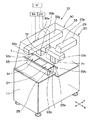
<モジュールの共通構成>
ここで、第1モジュール10のみの模式的な拡大斜視図を図2に示す。図2に示すように、第1モジュール10は、略長方形状の平面を有する機台の一例である1つのプラットホーム11を備えており、プラットホーム11の上面においては、半田塗布供給工程Aを行う第1ユニット20(図示X軸方向右側のユニット)と、チップ部品装着工程Bを行う第2ユニット30(図示Y軸方向左側のユニット)との夫々の構成部材が備えられている。また、第1ユニット20及び第2ユニット30の夫々はプラットホーム11が共通されるように、プラットホーム11に備えられている。
【0033】
第1ユニット20及び第2ユニット30の夫々においては、第1搬送装置22のレール22a又は第2搬送装置32のレール32aがプラットホーム11上に備えられた基板支持台25及び35に支持されている。また、第1搬送装置22のレール22a又は第2搬送装置32のレール32aにより支持されながら搬送経路沿いに搬送されて第1作業位置21又は第2作業位置31の夫々に固定された回路基板1に対して、夫々の所定の作業を行うヘッド部が第1ユニット20及び第2ユニット30の夫々に装備されて、上記装備された夫々のヘッド部を個別に図示X軸方向又はY軸方向に移動させるヘッド部駆動装置の一例である第1XYロボット23が第1ユニット20に、第2XYロボット33が第2ユニット30に夫々備えられている。第1XYロボット23は上記ヘッド部を着脱可能に装備させることができるヘッド部取付部の一例である第1ヘッド部取付部23aを有し、同様に第2XYロボット33は第2ヘッド部取付部33aを有し、かつ第1ヘッド部取付部23a、及び第2ヘッド部取付部33aとともに第1ヘッド部取付部23a、及び第2ヘッド部取付部33aに装備された夫々のヘッド部を個別に図2の図示X軸方向に進退移動させるX軸ロボット23x、33xと、夫々のX軸ロボット23x、33xとが取り付けられ、かつ夫々のX軸ロボット23x、33xを図2の図示Y軸方向に個別に進退移動させるY軸ロボット23y、33yとを備えている。これにより、第1XYロボット23及び第2XYロボット33による夫々のヘッド部の図示X軸方向又はY軸方向の移動が可能となっている。なお、図1、図2、及び図15において、X軸方向とY軸方向とは互いに直交しており、回路基板1の上記搬送経路は、図示X軸方向に沿って形成されている。
【0034】
また、第1ユニット20は、第1XYロボット23によるヘッド部の移動動作、上記ヘッド部の動作、及び、第1搬送装置22による回路基板1の移動動作を制御するユニット制御部の一例である第1ユニット制御部24を備えており、同様に、第2ユニット30は、第2XYロボット33によるヘッド部の移動動作、上記ヘッド部の動作、及び、第2搬送装置32による回路基板1の移動動作を制御するユニット制御部の一例である第2ユニット制御部34を備えている。また、第1モジュール10においては、第1ユニット制御部24と第2ユニット制御部34との夫々の制御を一括して管理するとともに両者間の制御の調整を行う主制御部の一例である第1メイン制御部12を備えている。なお、第1ユニット制御部24、及び第2ユニット制御部34と、第1メイン制御部12と、上記夫々の動作制御との制御的な関係の説明については後述する。
【0035】
このように、第1モジュール10においては、第1ヘッド部取付部23aを有する第1XYロボット23と、第1搬送装置22と、第1ユニット制御部24とを備える第1ユニット20と、第2ヘッド部取付部33aを有する第2XYロボット33と、第2搬送装置32と、第2ユニット制御部34とを備える第2ユニット30とが、共通のプラットホーム11に備えられ、さらに、第1メイン制御部12が備えられており、このような構成がモジュールの共通的な構成(以降、モジュールの共通構成という)となっており、第2モジュール40もこのモジュールの共通構成を有している。
【0036】
また、第1XYロボット23の第1ヘッド部取付部23aには、複数の種類のヘッド部の中から選択された任意の1つのヘッド部が着脱可能に取り付けることができるように、上記複数のヘッド部の取付部の形状は共通化されている。また、第2XYロボット33の第2ヘッド部取付部33aは、第1ヘッド部取付部23aと同様な形状を有しており、上記複数の種類のヘッド部の中から選択された任意の1つのヘッド部を着脱可能に取り付けることが可能となっている。従って、回路基板1に対して電極上にクリーム半田の塗布供給を行う接合材供給ヘッド部の一例である塗布供給ヘッド部71が選択されて、第1ユニット20における第1ヘッド部取付部23aに塗布供給ヘッド部71が装備されることにより、第1ユニット20において、半田塗布供給工程Aを行うことが可能となっている。また、回路基板1に対して半田を介してチップ部品の装着を行う部品装着ヘッド部の一例であるチップ部品装着ヘッド部72が選択されて、第2ユニット30における第2ヘッド部取付部33aにチップ部品装着ヘッド部72が装備されることにより、第2ユニット30において、チップ部品装着工程Bを行うことが可能となっている。
【0037】
なお、図15に示すように、第1モジュール10において、第1モジュール10の図示X軸方向沿いの長さ寸法をW0と、第1ユニット20及び第2ユニット30の第1作業位置21及び第2作業位置31の夫々における図示X軸方向沿いの長さ寸法をW1とすると、W1はW0の1/3以下の寸法となっている。また、第1ユニット20において、第1XYロボット23によるヘッド部のX軸方向における移動可能範囲は、第1作業位置21の上記長さ寸法W1に合致する範囲内に機械的に制限されており、また、同様に、第2ユニット30において、第2XYロボット33によるヘッド部のX軸方向における移動可能範囲は、第2作業位置31の上記長さ寸法W1に合致する範囲内に機械的に制限されている。これにより、第1ユニット20において、第1XYロボット23により塗布供給ヘッド部71の移動動作が行われ、かつ、第2ユニット30において、第2XYロボット33によりチップ部品装着ヘッド部72の移動動作が行われるような場合であっても、第1XYロボット23、第2XYロボット33、塗布供給ヘッド部71、及びチップ部品装着ヘッド部71の夫々は互いに干渉することが確実に防止されている。なお、このような構成も上記モジュールの共通構成の1つとなっており、第2モジュール40についても同様な構成となっている。
【0038】
なお、本第1実施形態においては、一例として、第1モジュール10及び第2モジュール40の図示X軸方向沿いの長さ寸法W0が夫々600mm、第1ユニット20、第2ユニット30、第1ユニット50、及び第2ユニット60の夫々における第1作業位置21、第2作業位置31、第1作業位置51、及び第2作業位置61の図示X軸方向沿いの長さ寸法W1が夫々200mmとなっている。
【0039】
<制御部の構成について>
また、第1ユニット20においては、第1XYロボット23によるヘッド部の移動動作、すなわち、塗布供給ヘッド部71の移動動作の制御を行う駆動装置制御部の一例である第1XYロボット制御部23bが備えられており、また、塗布供給ヘッド71には、クリーム半田の供給動作の制御を行うヘッド部制御部の一例である塗布供給ヘッド部制御部71aが備えられている。また、同様に、第2ユニット30においては、第2XYロボット33によるヘッド部の移動動作、すなわち、チップ部品装着ヘッド部72の移動動作の制御を行う駆動装置制御部の一例であるXYロボット制御部33bが備えられており、また、チップ部品装着ヘッド部72には、チップ部品の装着動作の制御を行うヘッド部制御部の一例であるチップ部品装着ヘッド部制御部72aが備えられている。
【0040】
ここで、第1メイン制御部12、第1ユニット制御部24及び第2ユニット制御部34、第1XYロボット制御部23b及び第2XYロボット制御部33b、塗布供給ヘッド部制御部71a及びチップ部品装着ヘッド部制御部72aの夫々の関係を図3に示す。図3に示すように、第1XYロボット制御部23bと塗布供給ヘッド部制御部71aは、第1ユニット制御部24を介して第1メイン制御部12に接続されており、また、第2XYロボット制御部33bとチップ部品装着ヘッド部制御部72aは、第2ユニット制御部34を介して、第1メイン制御部12に接続されている。
【0041】
第1ユニット制御部24と第2ユニット制御部34とは互いに同様な機能を有しているため、その機能について第2ユニット制御部34を代表として説明すると、第2ユニット制御部34は、第1メイン制御部12より発せられた制御指令を、その指令内容に基づいて第2XYロボット制御部33b又はチップ部品装着ヘッド部制御部72aに伝達させる機能を有している。また、逆に、第2ユニット制御部34は、第2XYロボット制御部33b又はチップ部品装着ヘッド部制御部72aのいずれか一方より出力された信号をその信号の内容に基づいて、第1メイン制御部12へ出力するものと、第2XYロボット制御部33b又はチップ部品装着ヘッド部制御部72aのいずれか他方に出力するものとの判断を行った上で伝達させる機能も有している。
【0042】
具体例でもって説明すると、例えば、第1メイン制御部12から第2ユニット制御部34に出力される指令内容としては、第2XYロボット33の動作開始/終了指令やチップ部品装着ヘッド72の動作開始/終了指令等があり、これらの指令が第2ユニット制御部34に入力されて、第2ユニット制御部34より指令内容に基づいて第2XYロボット制御部33b又はチップ部品装着ヘッド部制御部72aに入力されて、入力された指令内容に基づいて第2XYロボット制御部33bにより第2XYロボット33の動作、又は、チップ部品装着ヘッド部制御部72aによりチップ部品装着ヘッド部72の動作が開始又は終了される。
【0043】
また、例えば、第2XYロボット制御部33b又はチップ部品装着ヘッド部制御部72bから第2ユニット制御部34に入力される信号としては、第2XYロボット33やチップ部品装着ヘッド部72の動作開始/終了や動作エラーの信号等があり、このような信号は第2ユニット制御部34より第1メイン制御部12に入力される。
【0044】
一方、チップ部品装着ヘッド部72と第2XYロボット33は互いの動作が関係づけられながら、チップ部品の装着動作が行われる。すなわち、チップ部品装着ヘッド部72が第2XYロボット33により目標位置に移動されないと、チップ部品装着ヘッド部72によるチップ部品の装着を行うことができず、逆に、チップ部品装着ヘッド部72によりチップ部品が装着されている間は第2XYロボット33によるチップ部品装着ヘッド部72の移動を行うことはできない。そのため、第2XYロボット制御部33bから出力されるチップ部品装着ヘッド部72によるチップ部品の装着動作可能の信号や、チップ部品装着ヘッド部制御部72aから出力される第2XYロボット33によるチップ部品装着ヘッド部72の移動動作可能の信号が、第2ユニット制御部34に入力されるとともに、第2XYロボット制御部33b又はチップ部品装着ヘッド部制御部72aのいずれか他方(すなわち、上記信号が出力されていない制御部)に入力されて、第2XYロボット33とチップ部品装着ヘッド部72との夫々の動作が互いに関係付けられて行うことが可能となる。なお、このときこれらの信号は第2ユニット制御部34より第1メイン制御部12に入力されることはない。なお、このような制御方法を本明細書においては、「分散制御」というものとするが、この分散制御を積極的に利用することができる制御手法については後述する別の実施形態において説明するものとする。
【0045】
なお、第2ユニット制御部34と同様な機能を有している第1ユニット制御部24においては、上記チップ部品装着ヘッド部制御部72aによるチップ部品装着ヘッド部72のチップ部品装着動作を、塗布供給ヘッド部制御部71aによる塗布供給ヘッド部71のクリーム半田の供給動作に置き換えた制御動作を行うことができる。
【0046】
<部品実装基板生産装置101の詳細説明>
再び図1に戻って、部品実装基板生産装置101について説明する。
【0047】
第2モジュール40も第1モジュール10の上述した構成と同様な構成、すなわちモジュールの共通構成を有している。図1に示すように、第2モジュール40は、機台の一例であるプラットホーム41と主制御部の一例である第2メイン制御部42とを備えている。また、第1ユニット50及び第2ユニット60は、第1ヘッド部取付部53aを有するヘッド部駆動装置の一例である第1XYロボット53と、第2ヘッド部取付部63aを有するヘッド部駆動装置の一例である第2XYロボット63と、ユニット制御部の一例である第1ユニット制御部54、及び第2ユニット制御部64とを備えている。
【0048】
また、第1ユニット50においては、部品装着ヘッド部の一例であるチップ部品装着ヘッド部72が第1XYロボット53のヘッド部取付部53aに着脱可能にかつ選択的に装備されており、これにより、第1ユニット50においては、チップ部品装着工程Cを行うことが可能となっている。また、第2ユニット60においては、部品装着ヘッドの一例であるIC部品接合ヘッド73が第2XYロボット63の第2ヘッド部取付部63aに着脱可能にかつ選択的に装備されており、これにより、第2ユニット60においては、IC部品接合工程Dを行うことが可能となっている。
【0049】
また、第1モジュール10における場合と同様に、第2モジュール40においても、第1XYロボット53は第1XYロボット制御部53bを備え、第2XYロボット63は第2XYロボット制御部63bを備え、さらに、チップ部品装着ヘッド部72はチップ部品装着ヘッド部制御部72aを備え、IC部品接合ヘッド部73はIC部品接合ヘッド部制御部73aを備えている。ここで、部品実装基板生産装置101におけるこれら夫々の制御部の関係を図16に示す。図16に示すように、第1メイン制御部12と第2メイン制御部42とは互いに接続されており、第1モジュール10と第2モジュール40との間で情報の出入力が可能となっている。また、図16において図示しないが、夫々のユニットにおける搬送装置の搬送動作の制御を行う搬送制御部が、夫々のユニット制御部に接続されており、すなわち、第1モジュール10の第1ユニット20における第1搬送装置22の搬送動作の制御を行う第1搬送制御部(図示しない)が第1ユニット制御部24に接続されており、同様に第2搬送装置32の搬送動作の制御を行う第2搬送制御部(図示しない)が第2ユニット制御部34に接続されており、第2モジュール40における第1搬送装置52の搬送動作の制御を行う第1搬送制御部(図示しない)が第1ユニット制御部54に接続されており、第2搬送装置62の搬送動作の制御を行う第2搬送制御部(図示しない)が第2ユニット制御部64に接続されている。これにより、例えば、第1モジュール10における第1搬送装置22及び第2搬送装置32から、第2モジュール40における第1搬送装置52及び第2搬送装置62までにおいて、夫々の搬送制御部、夫々のユニット制御部、及び夫々のメイン制御部を介して、回路基板1の搬送動作に関する情報の出入力が行われながら部品実装基板生産装置101における回路基板1の搬送動作の制御が行われる。
【0050】
また、図16に示すように、第1ユニット20において、塗布供給ヘッド部71をヘッド部取付部23aから取り外すことにより第1ユニット制御部24と塗布供給ヘッド部制御部71aとの接続が解除可能であり、逆に、塗布供給ヘッド部71をヘッド部取付部23aに取り付けることにより第1ユニット制御部24と塗布供給ヘッド部制御部71aとを接続することが可能となっている。第2ユニット30におけるチップ部品装着ヘッド部制御部72aについて、また、第1ユニット50におけるチップ部品装着ヘッド部制御部72aについて、さらに、第2ユニット60におけるIC部品接合ヘッド部制御部73aについても、上記接続又は接続解除に関し夫々上記同様な関係となっている。なお、図16における部品供給制御部81b及び82bの説明については後述する。
【0051】
なお、部品実装基板生産装置101においては、電子部品が実装される複数の回路基板1を連続的に部品実装基板生産装置101の搬送経路に供給する基板供給装置が、図1におけるモジュール10の図示右側に備えられており、また、電子部品が実装された複数の回路基板1を連続的に上記搬送経路から取り出して収納する基板収納装置が、図1のモジュール40の図示左側に備えられている。なお、上記基板供給装置及び上記基板収納装置は、図1において図示しないが、部品実装基板生産装置101に供給する回路基板1の数量等に応じた仕様のものを選定することができ、公知の基板供給装置及び基板収納装置を用いることができる。
【0052】
<ヘッド部の構造説明>
ここで、夫々のユニットにおいて、準備されたヘッド部の構造について図面を用いて説明する。図4において、(A)はチップ部品装着ヘッド部72の模式斜視図であり、(B)はIC部品接合ヘッド部73の模式斜視図であり、(C)は塗布供給ヘッド部71の模式斜視図である。
【0053】
まず、図4(A)に示すように、チップ部品装着ヘッド部72は上部に夫々のXYロボットのヘッド部取付部と着脱可能に係合固定可能な形状を有する取付部72dを備えており、例えば、第2ヘッド部取付部33aと取付部72dと着脱可能に係合固定されることにより、チップ部品装着ヘッド部72が第2XYロボット33に装備される。また、チップ部品装着ヘッド部72の下部には、チップ部品2を解除可能に吸着保持する吸着ノズル72bが複数(例えば5本)備えられており、各々の吸着ノズル72bの先端においてチップ部品2を個別に吸着保持することができる。また、夫々の吸着ノズル72bの昇降動作を個別に行う昇降装置72cが備えられており、供給されるチップ部品2の吸着取出しの際や、吸着保持されているチップ部品2の回路基板1への装着動作の際等には、昇降装置72cにより該当する吸着ノズル72bの昇降動作が行われる。なお、このように複数の吸着ノズル72bが備えられているチップ部品装着ヘッド部72は、マルチノズルヘッド部と呼ばれる場合もあり、これら複数の吸着ノズル72bにより同時に複数のチップ部品2を一括して吸着保持して、吸着保持されたチップ部品2を回路基板1に連続的に装着させることができるため、効率的なチップ部品2の装着動作を行うことができる。その他、部品装着ヘッドの一例としては、IC部品の装着を行うIC部品装着ヘッドもある。
【0054】
また、図4(B)に示すように、IC部品接合ヘッド部73は上部に夫々のXYロボットのヘッド取付部と着脱可能に係合固定可能な形状を有する取付部73dを備えており、例えば、第2ヘッド部取付部63aと取付部73dとが着脱可能に係合固定されることにより、IC部品接合ヘッド73が第2XYロボット63に装備される。また、IC部品接合ヘッド73の下部には、IC部品3を解除可能に吸着保持する吸着ノズル73bが備えられており、吸着ノズル73bの先端においてIC部品3を吸着保持することができる。また、吸着ノズル73bの昇降動作を行う昇降装置73cが備えられており、供給されるIC部品3の吸着取出しの際や、吸着保持されているIC部品3の回路基板1への装着動作の際等には、上記昇降装置73cにより吸着ノズル73bの昇降動作が行われる。また、IC部品接合ヘッド部73は、吸着保持したIC部品3を回路基板1のIC部品の接合位置に当接させた状態で、IC部品3に対して超音波振動を付与することにより、回路基板1にIC部品3を接合することが可能となっている。
【0055】
また、図4(C)に示すように、塗布供給ヘッド部71は上部に夫々のXYロボットのヘッド部取付部と着脱可能に係合固定可能な形状を有する取付部71dを備えており、例えば、第1ヘッド部取付部23aと取付部71dとが着脱可能に係合固定されることにより、塗布供給ヘッド部71が第1XYロボット23に装備される。また、図4(C)における塗布供給ヘッド部71の前面にクリーム半田が供給可能に収容されている半田供給部71eが備えられており、塗布供給ヘッド部71の下部には回路基板1にクリーム半田を個別に塗布により供給する塗布ノズル71bが複数(例えば、3本)備えられている。各塗布ノズル71bは半田供給部71eに接続されており、半田供給部71eに圧縮空気等を供給することにより、半田供給部71e内に収容されているクリーム半田を選択された塗布ノズル71bに所定量だけ送り出して、当該塗布ノズル71bの下端よりクリーム半田を押し出すようにして供給することが可能となっている。また、塗布供給ヘッド部71には各塗布ノズル71bの昇降動作を個別に行う昇降装置71cが備えられており、回路基板1へのクリーム半田の塗布供給の際には、昇降装置71cにより選択された塗布ノズル71bの昇降動作が行われる。
【0056】
なお、この塗布供給ヘッド部71の詳細な構造を示す斜視図を図5に示す。但し、図5に示すように、この塗布供給ヘッド部71は、塗布ノズル71bを2本備える仕様のものであること、ヘッドフレーム71cの前面に、回路基板1上の半田供給位置を撮像することにより半田供給位置を認識する認識カメラ71fが備えられている点において、上述した塗布供給ヘッド71とは仕様が異なっている。
【0057】
図5に示すように、塗布供給ヘッド部71の上部には夫々のXYロボットのヘッド部取付部と着脱可能に係合固定可能な取付部71dが備えられている。取付部71dはその上面が略方形状の平面を有しており、さらに、上記略方形状の平面の隅部には固定部の一例であるボルト取付穴71gが形成されており、ヘッド部取付部への係合固定の際には夫々のボルト取付穴71gにボルトが通されてナットにより着脱可能に固定される。また、上記平面の中央付近には、位置決め部の一例である2つのピン穴71hが形成されており、夫々のヘッド取付部に設けられている位置決めピンと夫々のピン穴71hが係合されることにより、塗布供給ヘッド部71とXYロボットの取付部との取付位置の位置合わせが行われる。
【0058】
なお、図5は塗布供給ヘッド部71を示しているが、他のヘッド部においても上述のようなボルト取付穴71gとピン穴71hを有する共通化された形状を有する取付部が備えられている。
【0059】
<部品供給部の選択的な追加装備>
また、夫々のモジュールにおける夫々のユニットにおいては、上記のようなモジュールの共通構成を含めた構成に加えて、複数の電子部品をヘッド部(例えば、チップ部品装着ヘッド部72又はIC部品接合ヘッド部73)により吸着保持して取出可能に供給する複数の種類の部品供給部の中から選択的に1つの部品供給部を着脱可能に装備させることが可能となっている。部品実装基板生産装置101においては、第1ユニット20が半田塗布供給工程Aを行う構成とされており電子部品の装着を行う工程ではないが、その他のユニット、すなわち、第2ユニット30、第1ユニット50、及び第2ユニット60においては供給された電子部品を回路基板1に装着若しくは接合する作業が行われるため、第2ユニット30、第1ユニット50、及び第2ユニット60において、選択された上記部品供給部が装備される。
【0060】
まず、チップ部品装着工程Bが行われる第2ユニット30においては、同じ種類の多数のチップ部品2を連続的供給可能に収容された部品供給カセット81aが複数備えられ、かつ、これらの部品供給カセット81aより各チップ部品2を連続的に供給する部品供給部の一例であるカセットフィーダ81(図6(A)に示す)が、モジュール10のプラットホーム11の背面左側(すなわち、図1の図示Y軸方向右側かつX軸方向左側、ただし、カセットフィーダ81は図示しない)に着脱可能に装備されている。なお、このカセットフィーダ81が装備される位置は上記位置のみに限定されるものではなく、図1のプラットホーム11の前面左側にも着脱可能に装備させることもできる。第2ユニット30においては、カセットフィーダ81によって取出し可能に供給されたチップ部品2が、チップ部品装着ヘッド部72の吸着ノズル72bの下端で吸着保持されることにより、チップ部品2の供給が行われる。また、同様にチップ部品装着工程Cを行う構成である第1ユニット50においても、図1において、カセットフィーダ81(図示しない)が、モジュール40のプラットホーム41の背面右側に着脱可能に装備されている(図1のプラットホーム41の前面右側に装備させることも可能)。
【0061】
また、IC部品接合工程Dを行う構成である第2ユニット60においては、図1において、多数のIC部品3が供給可能に配置された複数のトレイ82aを層状に積載する部品供給部の一例であるトレイ供給部82(図6(B)に示す)が、第2モジュール40のプラットホーム41の背面左側に着脱可能に装備されている。トレイ供給部82においては、積載されている複数のトレイ82aのうちより選択された1つのトレイ82aを、そこに配置されたIC部品3を取出し可能に、引き出す引出装置(図示しない)が備えられている。第2ユニット60においては、トレイ供給部82において引き出されたトレイ82a上に、供給可能に配置されたIC部品3が、IC部品接合ヘッド部73の吸着ノズル73bの下端で吸着保持されることにより、IC部品3のIC部品接合ヘッド部73への供給が行われる。なお、このトレイ供給部82が装備される位置は上記位置のみに限定されるものではなく、図1のプラットホーム41の前面左側にも着脱可能に装備させることもできる。
【0062】
なお、夫々のユニットに装備されたカセットフィーダ81及びトレイ供給部82は、夫々のユニットにおいて必要とされない場合等には、容易に夫々のユニットへの装備を解除して取り外すことが可能となっている。
【0063】
なお、カセットフィーダ81には、夫々の部品供給カセット81aの部品送出し動作等を制御可能な部品供給制御部81bが備えられており、また、トレイ供給部82には、選択されたトレイ82aの引出装置による引き出し動作等を制御可能な部品供給制御部82bが備えられている。また、第2ユニット30においては、部品供給制御部81bは第2ユニット制御部34に接続されており、第1ユニット50においては、部品供給部81bは第1ユニット制御部54に接続されており、さらに、第2ユニット60においては部品供給部82bは第2ユニット制御部64に接続されている。これらの制御関係を図16に示す。図16に示すように、第1モジュール10の第2ユニット制御部34に接続された部品供給制御部81bは、第2ユニット制御部34を介して第1メイン制御部12に接続されており、第1メイン制御部12から出力されるカッセトフィーダ81によるチップ部品2の供給動作の開始/終了指令等が第2ユニット制御部34を介して部品供給制御部81bに入力されることにより、カセットフィーダ81によるチップ部品2の供給開始/終了の動作の制御が行われる。また、部品供給制御部81bは第2ユニットを介して第2XYロボット制御部33b及びチップ部品装着ヘッド部制御部72aとの間での情報の出入力が可能となっており、例えば、カセットフィーダ81においてチップ部品2が供給可能となっているという情報が、部品供給制御部81bから第2ユニット制御部34に出力されて、上記情報が第2ユニット制御部34からチップ部品装着ヘッド部制御部72aに入力されて、チップ部品装着ヘッド部72によりカセットフィーダ81から上記チップ部品2の吸着取出しを行うことができる。なお、第1ユニット制御部54に接続されている部品供給制御部81b、第2ユニット制御部64に接続されている部品供給制御部82bにおいても、第2ユニット制御部34に接続されている部品供給制御部81bと同様な制御関係を有している。また、第2ユニット30からカセットフィーダ81を取り外すことにより、第2ユニット制御部34と部品供給制御部81bとの接続は解除され、また、第1ユニット50からカッセトフィーダ81を取り外すことにより、第1ユニット制御部54と部品供給制御部81bとの接続は解除され、さらに、第2ユニット60からトレイ供給部82を取り外すことにより、第2ユニット制御部64と部品供給制御部82bとの接続が解除される。
【0064】
<部品実装基板生産装置101による部品実装基板生産工程の説明>
次に、このような構成の部品実装基板生産装置101において、基板供給装置から供給される回路基板1に対して電子部品の実装処理を行い、部品実装基板を生産する動作について説明する。また、図7及び図8は、回路基板1及び回路基板1に実装される電子部品の模式的な断面図を用いて、上記動作を示したものである。
【0065】
まず、図1において、基板供給装置(図示しない)から、第1モジュール10の第1ユニット20における第1搬送装置22に回路基板1が供給され、供給された回路基板1は第1搬送装置22により第1ユニット20の第1作業位置21まで搬送されて、第1作業位置21において回路基板1が位置決めされて保持される。図7(A)に示すように四角形プレート状の回路基板1は、その上面に電子部品が実装される多数の電極が形成されており、これら多数の電極として、複数のチップ部品2の夫々の電極2aが接合される多数の電極1a及び1bと、IC部品3の夫々の電極3aが接合される多数の電極1cとが形成されている。
【0066】
次に、第1ユニット20において、第1XYロボット23により塗布供給ヘッド部71が図1の図示X軸方向又はY軸方向へ移動されて、第1作業位置21に保持された回路基板1に対して、塗布供給ヘッド部71が備える塗布ノズル71bと、クリーム半田が供給される回路基板1上の多数の電極1aのうちの1つの電極1aとの位置合わせが行われる。上記位置合わせが行われた後、塗布供給ヘッド71の昇降装置71cにより上記位置合わせが行われた塗布ノズル71bが下降されて、塗布ノズル71bの下方先端より、回路基板1の電極1a上にクリーム半田が供給される。適切な量のクリーム半田の供給が行われた後、クリーム半田の供給が停止され、塗布ノズル71bが昇降装置71cにより上昇される。これにより、回路基板1の電極1a上にクリーム半田により形成された半田部4が形成される。それとともに、別の塗布ノズル71bと回路基板1上において次にクリーム半田の供給が行われる1つの電極1bとの位置合わせが上記同様に行われる。この位置合わせの後、上記別の塗布ノズル71bが昇降装置71cにより下降されて、上記別の塗布ノズル71bの下方先端より、回路基板1の電極1b上に適切な量のクリーム半田が供給される。図7(B)はこの状態を示している。その後、クリーム半田の供給が停止され、上記別の塗布ノズル71bが昇降装置71cにより上昇される。これにより、回路基板1の電極1b上にクリーム半田により形成された半田部4が形成される。なお、回路基板1におけるIC部品3が接合される各電極1cに対しては、クリーム半田の供給は行われない。クリーム半田を供給すべき全ての電極に対し、クリーム半田の供給を行って夫々の電極上に半田部4を形成した後、作業位置21における回路基板1の保持が解除されて、第1搬送装置22により第2ユニット30への回路基板1の搬送が行われる。
【0067】
次に、図1において、第1ユニット20の第1搬送装置22から、第2ユニット30における第2搬送装置32に回路基板1が受け渡されて、受け渡された回路基板1は第2搬送装置32により第2ユニット30の第2作業位置31まで搬送されて、第2作業位置31において回路基板1の搬送位置が位置決めされて保持される。
【0068】
一方、第2ユニット30においては、第2XYロボット33によりチップ部品装着ヘッド部72が図1の図示X軸方向又はY軸方向に移動されて、カセットフィーダ81の上方へと移動される。カセットフィーダ81が備える複数の部品供給カセット81aの中より回路基板1に装着されるチップ部品2を供給する1つの部品供給カセット81aが選択されて、チップ部品装着ヘッド部72が備える複数の吸着ノズル72bのうちの1つの吸着ノズル72bと、上記選択された部品供給カセット81aの部品供給位置に取り出し可能に配置されているチップ部品2との位置合わせが行われる。この位置合わせの後、チップ部品装着ヘッド72が備える昇降装置72cにより吸着ノズル72bが下降されて、吸着ノズル72bの下端にてチップ部品2の上面が吸着保持される。その後、吸着ノズル72bがチップ部品2を吸着保持したまま上昇されることにより、チップ部品2がカセットフィーダ81より取り出される。なお、複数の吸着ノズル72bによりチップ部品2の吸着取出しが行われるような場合にあっては、上記動作を順次繰り返して、又は同時的に行う。また、複数の吸着ノズル72bにより複数の部品供給カセット81aからチップ部品2を同時的に取り出すような場合であってもよい。
【0069】
その後、図7(C)に示すように、第2XYロボット33によりチップ部品装着ヘッド部72が第2作業位置31に保持された回路基板1の上方へと移動されて、回路基板1におけるチップ部品2が装着されるべき1つの装着位置における各電極1aと吸着ノズル72bにより吸着保持されているチップ部品2の各電極2aとの位置合わせが行われる。この位置合わせの後、図7(D)に示すように、チップ部品装着ヘッド部72の昇降装置72cにより、上記位置合わせが行われた吸着ノズル72bが下降され、回路基板1の各電極1a上に形成された半田部4を介して、回路基板1の各電極1aにチップ部品2の各電極2aを押圧する。その後、吸着ノズル72bによるチップ部品2の吸着保持を解除するとともに、昇降装置72cにより吸着ノズル72bを上昇させる。これにより、半田部4を介して回路基板1の各電極1aにチップ部品2の各電極が装着される。複数のチップ部品2を回路基板1に装着するような場合にあっては、上記動作を順次繰り返して行うことにより、上記複数のチップ部品2を順次回路基板1に装着する。その後、第2作業位置31における回路基板1の保持が解除されて、第2搬送装置32により次の第1ユニット50への回路基板1の搬送が行われる。
【0070】
次に、図1において、第2ユニット30の第2搬送装置32から、第1ユニット50における第1搬送装置52に回路基板1が受け渡されて、受け渡された回路基板1は第1搬送装置52により第1ユニット50の第1作業位置51まで搬送されて、第1作業位置51において回路基板1の搬送位置が位置決めされて保持される。
【0071】
その後、図8(E)及び(F)に示すように、第2ユニット30における場合と同様に、第1ユニット50において、カセットフィーダ81の1つの部品供給カセット81aからチップ部品装着ヘッド部72によりチップ部品2を吸着保持して取り出し、チップ部品装着ヘッド部72によりチップ部品2の電極2aを回路基板1の電極1b上に形成された半田部4を介してチップ部品2の電極2aを回路基板1の電極1bに装着する。なお、第1ユニット50におけるカセットフィーダ81から供給されるチップ部品2は、第2ユニット30におけるカセットフィーダ81から供給されるチップ部品2と同じ種類のチップ部品2である場合、若しくは異なる種類のチップ部品2でもよく、部品実装基板生産装置101において回路基板1に実装される電子部品の種類や数量等に合わせて、第2ユニット30及び第1ユニット50に供給されるチップ部品2の種類を決めることができる。その後、第1作業位置51における回路基板1の保持が解除されて、第1搬送装置52により次の第2ユニット60への回路基板1の搬送が行われる。
【0072】
次に、図1において、第1ユニット50の第1搬送装置52から、第2ユニット60における第2搬送装置62に回路基板1が受け渡されて、受け渡された回路基板1は第2搬送装置62により第2ユニット60の第2作業位置61まで搬送されて、第2作業位置61において回路基板1の搬送位置が位置決めされて保持される。
【0073】
第2ユニット60においては、トレイ供給部82が備える複数のトレイ82aの中より回路基板1に接合されるIC部品3を供給する1つのトレイ82aが選択されて、上記選択されたトレイ82aがトレイ供給部82の引出装置(図示しない)により予め引き出されて、引き出されたトレイ82a上においては、夫々のIC部品3が取り出し可能な状態とされている。また、図8(G)に示すように、IC部品3は図示下面において複数の電極3aを有しており、さらに各電極3aには半田等の金属材料により形成される突起状の接合電極の一例である(接合材の一例でもある)バンプ3bが夫々形成されており、この夫々のバンプ3bが回路基板1におけるIC部品3の接合位置における電極1cと接合可能となっている。また、トレイ82aにおいては、電極3aが形成されていない面である背面を上向きとして複数のIC部品3が格子状に整然と配列されている。
【0074】
また、第2XYロボット63によりIC部品接合ヘッド部73が図1の図示X軸方向又はY軸方向に移動されて、トレイ供給部82の上記選択されたトレイ82aの上方へと移動される。その後、IC部品接合ヘッド部73の吸着ノズル73bと、上記選択されたトレイ82aにおける1つのIC部品3との位置合わせが行われる。この位置合わせの後、IC部品接合ヘッド73が備える昇降装置73cにより吸着ノズル73bが下降されて、吸着ノズル73bの下端によりIC部品3の上記背面が吸着保持され、その後、吸着ノズル73bがIC部品3を吸着保持したまま上昇されることにより、IC部品3がトレイ82aより取り出される。
【0075】
その後、第2XYロボット63によりIC部品接合ヘッド部73が第2作業位置61に保持された回路基板1の上方へと移動されて、回路基板1におけるIC部品3が接合される各電極1cと吸着ノズル73bにより吸着保持されているIC部品3の各バンプ3bとの位置合わせが行われる。この位置合わせの後、図8(H)に示すように、IC部品接合ヘッド部73の昇降装置73cにより、上記位置合わせが行われた吸着ノズル73bが下降され、IC部品3の各バンプ3bが回路基板1の電極1cと当接され、さらに、各バンプ3bが各電極3aに押圧される。それとともに、IC部品接合ヘッド部73によりIC部品3に対して超音波振動が付与されて、IC部品3の各バンプ3bと回路基板1の各電極3aとが接合される。その後、吸着ノズル73bによるIC部品3の吸着保持を解除するとともに、昇降装置73cにより吸着ノズル73bを上昇させる。これにより、IC部品3の各電極3aが各バンプ3bを介して回路基板1の各電極1cに接合されて、IC部品3が回路基板1に実装される。複数のIC部品3を回路基板1に接合するような場合にあっては、上記動作を順次繰り返して行うことにより、上記複数のIC部品3を回路基板1に接合する。
【0076】
その後、第2作業位置61における回路基板1の保持が解除されて、第2搬送装置62により、第2モジュール40に隣接して配置されている基板収納装置(図示しない)に、チップ部品2が装着されて、かつ、IC部品3が実装されて部品実装基板となった回路基板1が搬送されて収納される。
【0077】
なお、部品実装基板生産装置101においては、複数の回路基板1を連続的に搬送しながら夫々の回路基板1に対して順次上記夫々の作業を施すことにより、複数の部品実装基板を連続的に生産し、生産された複数の部品実装基板が順次上記基板収納装置に収納されることとなる。
【0078】
また、部品実装基板生産装置101における上記夫々の作業は、第1モジュール10に備えられている第1メイン制御部12、第2モジュール40に備えられている第2メイン制御部42、夫々のユニットに備えられている第1ユニット制御部24、第2ユニット制御部34、第1ユニット制御部54、及び第2ユニット制御部64、さらに夫々のXYロボットやヘッド部や部品供給部や搬送装置に備えられている第1XYロボット制御部23b、第2XYロボット制御部33b、第1XYロボット制御部53b、及び第2XYロボット制御部63bや、塗布供給ヘッド部制御部71a、チップ部品装着ヘッド部制御部72a、及びIC部品接合ヘッド部制御部73a、部品供給制御部81b及び82b、第1搬送制御部、第2搬送制御部により制御されることにより行われる。
【0079】
<部品実装基板生産装置101の構成変更>
このように構成され、複数の回路基板1よりチップ部品2が装着され、IC部品が接合された複数の部品実装基板を連続的に生産することができる部品実装基板生産装置101において、装着される電子部品の種類等が変更されて異なる種類の部品実装基板を生産する必要が発生した場合に、部品実装基板生産装置101の構成を変更して部品実装基板生産装置102を構成し、部品実装基板生産装置102により上記異なる種類の部品実装基板の生産に対応する方法について、以下に具体例を用いて説明する。
【0080】
上記具体例として、例えば、部品実装基板生産装置102において、部品実装基板生産装置101における場合と比べて、回路基板1に接合されるIC部品3の数量は変わらず、装着されるチップ部品2の数量が減少され、また、回路基板1にチップ部品2が装着された後、加熱することにより半田部4をリフローさせて、チップ部品2を回路基板1に接合して実装させた部品実装基板が生産されることが要求されるような場合について説明する。
【0081】
図9において、(A)に部品実装基板生産装置101の模式的な構成を示す模式説明図を、(B)に部品実装基板生産装置102の模式的な構成を示す模式説明図を示す。
【0082】
図9(A)に示すように、部品実装基板生産装置101は、第1ユニット20及び第2ユニット30を備える第1モジュール10と、第1ユニット50及び第2ユニット60を備える第2モジュール40とが隣接して配置され、図示右側より左側へ順に、第1ユニット20において半田塗布供給工程Aを、第2ユニット30においてチップ部品装着工程Bを、第1ユニット50においてチップ部品装着工程Cを、第2ユニット60においてIC部品接合工程Dを行うことが可能である。
【0083】
一方、図9(B)に示すように、部品実装基板生産装置102は、この部品実装基板生産装置101を構成している第1モジュール10及び第2モジュール40を用いて、夫々のユニットにおいてヘッド部等の部品が交換されることにより構成され、図示右側より左側へ順に、第1ユニット20において半田塗布供給工程Aを、第2ユニット30においてチップ部品装着工程Bを、第1ユニット50においてIC部品接合工程Dを、さらに、第2ユニット60においては、リフロー工程Eを行うことが可能となる。
【0084】
従って、部品実装基板生産装置101から102への変更にあたっては、第1モジュール10の構成は不変であるが、第2モジュール40において、第1ユニット50をチップ部品装着工程Cを行い得る構成からIC部品接合工程Dを行い得る構成へと変更するとともに、第2ユニット60をIC部品接合工程Dを行い得る構成から新たな工程であるリフロー工程Eを行い得る構成へと変更する必要がある。なお、リフロー工程Eにおいては、回路基板1に半田部4を介して装着されているチップ部品2を、半田部4を加熱して溶融させた後、冷却して固化させることにより、チップ部品2を回路基板1に接合させて実装させることが可能となっている。なお、部品実装基板生産装置102においては行われないが、リフロー工程Eにおいては、回路基板1に装着させたIC部品3のバンプ3bを加熱して溶融させることにより、IC部品3を回路基板1に接合して実装することも可能である。
【0085】
まず、図1における部品実装基板生産装置101における第2モジュール40の第1ユニット50において、第1XYロボット53の第1ヘッド部取付部53aとチップ部品装着ヘッド部72の取付部72dとの係合を解除して、すなわち、チップ部品装着ヘッド部72の取付部72dにおけるボルト取付穴(図4のボルト取付穴71gに相当)を通して第1ヘッド部取付部53aに係合固定させているボルト及びナットを緩めて、取り外すことにより上記係合固定を解除して、第1XYロボット53よりチップ装着ヘッド部72を取り外す。さらに、プラットホーム41に装備されているカセットフィーダ81を取り外す。それとともに、第2ユニット60において、第2XYロボット63の第2ヘッド部取付部63aとIC部品接合ヘッド部73の取付部73dとの係合を解除して(上記同様にボルト及びナットを取り外すことにより解除して)、第2XYロボット63よりIC部品接合ヘッド73を取り外す。さらに、プラットホーム41に装備されているトレイ供給部82を取り外す。この状態における部品実装基板生産装置101の模式的な斜視図を図10に示す。図10に示すように、第2モジュール40は、上記モジュールの共通構成のみにより構成された状態とされている。
【0086】
その後、図10に示す第2モジュール40において、上記第2ユニット60から取り外されたIC部品接合ヘッド73をその取付部73dにおいて第1ユニット50の第1XYロボット53の第1ヘッド部取付部73aに係合させて、上記ボルト及びナットを締め付けて固定することにより取り付けて、第1XYロボット53にIC部品接合ヘッド73を装備させる。同様に、上記第2ユニット60より取り外されたトレイ供給部82をプラットホーム41の背面右側に装備させる。
【0087】
ここで、半田部4やバンプ3b等の接合材にレーザービームを照射することにより上記接合材の溶融加熱を行うリフローヘッド部74の模式斜視図を図12に示す。
【0088】
図12に示すように、リフローヘッド部74は、その上部に夫々のXYロボットのヘッド部取付部と係合固定可能な形状を有する取付部74dを備え、また、下方先端にレーザービーム照射部74bを備えており、上記レーザービーム照射部74bより照射可能にレーザービームを発生させるレーザー発生器(図示しない)がリフローヘッド部74の内部に備えられている。また、図示しないが、リフローヘッド部74はリフローヘッド部74の動作制御を行うヘッド部制御部の一例であるリフローヘッド部制御部74aが備えられている。図10における第2ユニット60において、第2XYロボット63の第2ヘッド部取付部63aにリフローヘッド部74の取付部74aを係合させて取り付け、第2XYロボット63にリフローヘッド部74を装備させる。
【0089】
このようにして構成された部品実装基板生産装置102の模式的な斜視図を図11に示す。図11に示すように、第1ユニット50においては、トレイ供給部82のトレイ82a(図示しない)により取出可能に供給されるIC部品3を、IC部品接合ヘッド部73の吸着ノズル73bにより吸着保持して取り出して、回路基板1に接合することが可能、すなわち、IC部品接合工程Dを行うことが可能となる。また、第2ユニット60においては、チップ部品2が装着されて、かつ、IC部品3が接合された回路基板1が供給され、リフローヘッド部74のレーザービーム照射部74bよりレーザービームを、チップ部品2を回路基板1に装着している半田部4に対して照射することにより、半田部4をリフローさせて、その後固化させることによりチップ部品2を回路基板1に接合して実装することが可能、すなわち、リフロー工程Eを行うことが可能となる。なお、部品実装基板生産装置102においては行われないが、回路基板1の電極1cにバンプ3bを介してIC部品3が装着されているような場合にあっては、リフローヘッド部74のレーザービーム照射部74bよりレーザービームをバンプ3bに照射することにより、バンプ3bをリフローさせてIC部品3を回路基板1に接合して実装することも可能である。
【0090】
これにより、図9(B)に示すように、部品実装基板生産装置102は、第1ユニット20において半田塗布供給工程Aを、第2ユニット30においてチップ部品装着工程Bを、第1ユニット50においてIC部品接合工程Dを、第2ユニット60においてリフロー工程Eを行うことが可能となる。
【0091】
<部品実装基板生産装置102による部品実装基板生産工程の説明>
次に、このような部品実装基板生産装置102において、基板供給装置から供給される回路基板1に対して電子部品の実装処理を行い、部品実装基板を生産する動作について説明する。また、図13及び図14は、回路基板1及び回路基板1に実装される電子部品の模式的な断面図を用いて、上記動作を示したものである。なお、基板供給装置による回路基板1の供給から、第1ユニット50におけるIC部品接合工程Dまでは、上述した部品実装基板生産装置101におけるいずれかの工程と同様の作業が行われるため、夫々において行われる作業の説明を省略するものとし、第2ユニット60におけるリフロー工程Eについてのみ詳細に説明する。
【0092】
図13(A)〜(D)及び図14(E)及び(F)までに示すように、半田部4を介して回路基板1の夫々の電極1aにチップ部品2の各電極2aが装着され、かつ、各バンプ3bを介して回路基板1の夫々の電極1cにIC部品3の各電極3aが接合された回路基板1が、第1ユニット50の第1搬送装置52から第2ユニット60における第2搬送装置62に受け渡されて、上記受け渡された回路基板1は第2搬送装置62により第2ユニット60の第2作業位置61まで搬送されて、第2作業位置61において上記回路基板1が位置決めされて保持される。
【0093】
その後、図14(G)に示すように、リフローヘッド部74のレーザービーム照射部74bと回路基板1にチップ部品2を装着している半田部4との位置合わせが行われるように、第2XYロボット63によるリフローヘッド部74の図11の図示X軸方向又はY軸方向の移動が行われる。上記位置合わせが行われた後、レーザービーム照射部74bよりレーザービームが上記半田部4に照射され、このレーザービームの照射によって、上記半田部4が溶融される。その後、上記照射が停止され、上記溶融された半田部4が冷却されて固化され、上記半田部4を介してチップ部品2の電極2aが回路基板1の電極1cに接合される。複数のチップ部品2を装着している半田部4に対して上記動作を順次繰り返して行い、夫々の半田部4を介して夫々のチップ部品2の電極2aを回路基板1の電極1aに接合して実装させる。図14(H)は、チップ部品2及びIC部品3が回路基板1に接合されて実装された状態を示したものである。
【0094】
その後、第2作業位置61における回路基板1の保持が解除されて、第2搬送装置62により、第2モジュール40に隣接して配置されている基板収納装置に、チップ部品2及びIC部品3が実装されて部品実装基板となった回路基板1が搬送されて収納される。
【0095】
なお、部品実装基板生産装置102においては、部品実装基板生産装置101と同様に、複数の回路基板1を連続的に搬送しながら夫々の回路基板1に対して順次上記夫々の作業を施すことにより、複数の部品実装基板を連続的に生産し、生産された複数の部品実装基板が上記基板収納装置に順次収納されることとなる。
【0096】
また、部品実装基板生産装置102における上記夫々の作業は、第1モジュール10に備えられている第1メイン制御部12、第2モジュール40に備えられている第2メイン制御部42、夫々のユニットに備えられている第1ユニット制御部24、第2ユニット制御部34、第1ユニット制御部54、及び第2ユニット制御部64、さらに夫々のXYロボットやヘッド部や部品供給部に備えられている第1XYロボット制御部23b、第2XYロボット制御部33b、第1XYロボット制御部53b、及び第2XYロボット制御部63bや、塗布供給ヘッド部制御部71a、チップ部品装着ヘッド部制御部72a、IC部品接合ヘッド部制御部73a、及びリフローヘッド部制御部74aや、部品供給制御部81b及び82bにより制御されることにより行われる。
【0097】
なお、上記においては、一例として、部品実装基板生産装置101において第2モジュール40の構成のみに変更が必要な場合について説明したが、第1モジュール10の第1ユニット20及び第2ユニット30、及び第2モジュール40の第1ユニット50及び第2ユニット60は夫々同じ上記モジュールの共通構成を備えているため、いずれのユニットにおいて工程の変更が必要な場合であっても、上述の第1ユニット50及び第2ユニット60における工程の変更と同様な変更手順によって、上記工程の変更を行うことは可能である。
【0098】
上記第1実施形態によれば、以下のような種々の効果を得ることができる。
【0099】
まず、部品実装基板生産装置101を構成している夫々のモジュール(作業装置)は、基板の搬送経路沿いに直列的に配置された2つのユニットを備え、上記夫々のユニットは、複数の種類のヘッド部の中から1つのヘッド部を選択的にかつ着脱可能に取り付けることができるヘッド部取付部を有し、かつ、上記ヘッド部取付部に着脱可能に取り付けられたヘッド部をX軸方向又はY軸方向に移動させるXYロボットが、モジュールの共通構成として備えられているため、上記夫々のユニットにおいて、複数の種類のヘッド部の中から1つのヘッド部を選択して、ヘッド部取付部に着脱可能に取り付けて装備させることにより、装備されたヘッド部の種類に応じた工程を上記夫々のユニットにおいて行うことが可能となる。すなわち、従来の部品実装基板生産装置のように、夫々の作業装置において行われる工程のみを行うために必要な構成が夫々の作業装置において個別に備えられているのではなく、部品実装基板生産装置101の夫々のモジュールにおいては、上記モジュールの共通構成として、夫々のモジュールにおいて共通する構成が備えられ、夫々のユニットにおいて異なる最小限の構成であるヘッド部を、上記モジュールの共通構成に選択的にかつ着脱可能に装備させることができるようにしている。従って、部品実装基板生産装置101において生産される部品実装基板の機種変更等により工程の変更が必要となるような場合であっても、従来のように作業装置の入替え設置を行う必要がなく、上記モジュールの共通構成を有する夫々のモジュールにおける夫々のユニットにおいて、適切なヘッド部を選択して着脱可能に装備させるだけで、上記モジュールの共通構成を変更することなく、夫々のユニットにおいて行うことができる工程の変更を容易に行うことができる。
【0100】
具体的には、部品実装基板生産装置101において、例えば、第2モジュール40は、回路基板1の搬送経路沿いに直列的に配置された第1ユニット50及び第2ユニット60を備え、さらに、上記モジュールの共通構成として、第1ユニット50においては第1ヘッド部取付部53aを有する第1XYロボット53が備えられ、第2ユニット60においては第2ヘッド部取付部63aを有する第2XYロボット63が備えられているため、第1ヘッド部取付部53aに装備されたチップ部品装着ヘッド部72を取り外して、IC部品接合ヘッド部73を第1ヘッド部取付部53aに交換装備させることのみにより、第1ユニット50において行われる工程をチップ部品装着工程CからIC部品接合工程Dへと、上記モジュールの共通構成を変更することなく容易に工程の変更を行うことができる。また、同様に、第2ヘッド部取付部63aに装備されたIC部品接合ヘッド部73を取り外して、リフローヘッド部74を第2ヘッド部取付部63aに交換装備させることのみにより、第2ユニット60において行われる工程をIC部品接合工程Dからリフロー工程Eへと、上記モジュールの共通構成を変更することなく容易に工程の変更を行うことができる。
【0101】
従って、部品実装基板生産装置101において、工程の変更や拡張が必要な場合であっても、部品実装基板生産装置101を構成している夫々のモジュールを移動させることなく、また、夫々のモジュールが備える上記モジュールの共通構成を変更するもことなく、複数の種類のヘッド部の中から夫々の工程を行うために適切なヘッド部を選択して、夫々のユニットにおけるXYロボットに着脱可能に装備させることにより、部品実装基板生産装置における工程の変更に対応することができ、上記工程の変更に容易に対応することができる。よって、このようなモジュールにより構成される部品実装基板生産装置において、生産される部品実装基板の機種変更に対しても容易かつ柔軟に対応することができ、さらに、多品種少量生産にも効果的に対応することができる。
【0102】
また、このような効果は、部品実装基板生産装置101における夫々のモジュールにおいて、上記モジュールの共通構成としてメイン制御部及び夫々のユニット制御部等が備えられ、夫々のモジュールにおけるユニットに選択的にかつ着脱可能に装備されるヘッド部の制御を行うヘッド部制御部が夫々のヘッド部自体に備えられていることにより実現可能となるものである。すなわち、従来の作業装置のように、ヘッド部の制御を行うヘッド部制御部が、上記ユニット制御部やメイン制御部に備えられて、異なる種類へのヘッド部の交換を試みようとしても、上記ヘッド部の交換が上記メイン制御部等の大幅な改造等を伴い、困難なものとなるというのではなく、上記ユニットにおいて異なる種類のヘッド部を交換装備させるような場合であっても、上記メイン制御部等の構成の変更を伴うこともない。また、ヘッド部制御部がヘッド部自体に備えられていることにより、ヘッド部を装備させる場合に接続が必要な配線を少なくすることができ、ヘッド部の交換装備の作業を容易にすることができる。さらに、上記メイン制御部等に、上記ヘッド部制御部を備えさせないため、上記メイン制御部の構成をより簡単なものとすることができる。また、部品供給部についても、互いに異なる種類の制御を行う部品供給制御部が夫々の部品供給部自体に備えさせられているため、同様に、より様々な種類の部品供給部の装備にも対応することを可能とすることができる。従って、部品実装基板生産装置において様々な種類のヘッド部や部品供給部を容易に交換装備させることができ、部品実装基板の多品種小量生産により柔軟にかつ容易に対応することができる。
【0103】
さらに、上記モジュールの共通構成として、第1モジュール10において第1ユニット20及び第2ユニット30が備えられる共通のプラットホーム11が、第2モジュール40において第1ユニット50及び第2ユニット60が備えられる共通のプラットホーム41が夫々備えられ、夫々のプラットホーム11及び41に、電子部品の供給を行う複数の種類の部品供給部の中から選択的にかつ着脱可能に部品供給部を装備させることが可能とされていることにより、夫々のユニットにおいて行われる工程や供給する電子部品の種類に応じて、上記部品供給部として、カセットフィーダ81やトレイ供給部82を選択的にかつ着脱可能に装備させることができ、上記同様に部品実装基板生産装置における工程の変更に容易に対応することができる。
【0104】
また、部品実装基板生産装置101における上記工程の変更にあたっては、夫々のモジュール自体を交換することもなく、かつ、夫々のモジュールが有する上記モジュールの共通構成を変更することもなく、ヘッド部や部品供給部のみを工程に合わせて選択的に交換することにより上記工程の変更に対応することができる。そのため、このような部品実装基板生産装置のユーザーから見れば、部品実装基板の多品種少量生産等に対応するために、1つの種類の部品実装基板の生産において同時に用いられない複数種類の作業装置(第1実施態様におけるモジュールに対応)を保有することなく、複数種類のヘッド部や部品供給部のみを保有していれば、上記対応を行うことができる。よって、部品実装基板の多品種少量生産に対応するための生産設備に対する設備投資を抑制することができ、部品実装基板の生産コストを削減することができる。
【0105】
また、上記部品実装基板の多品種少量生産に対応するために、全ての種類の部品実装基板の生産に対応できる複数台若しくは複数種類の作業装置を部品実装基板生産装置に備えさせる必要も無くすことができ、単にヘッド部や部品供給部の交換、すなわち選択的な装備でもって対応することができるため、これにより、夫々の作業装置の稼動効率を低下させたり、部品実装基板生産装置の設置長さが長くなるといった問題を防止し、部品実装基板生産装置の設置長さを短縮化して、部品実装基板の単位面積当りの生産性を向上させることができる。
【0106】
<第2実施形態>
なお、本発明は上記実施形態に限定されるものではなく、その他種々の態様で実施できる。例えば、本発明の第2実施形態にかかる部品実装基板生産装置の一例である部品実装基板生産装置401は、上記第1実施形態の部品実装基板生産装置101のように、2つのユニットを備えるモジュールにより構成されるのではなく、1つのユニットを備える複数の作業装置(若しくはモジュールと言う場合であってもよいが、第1実施形態と区別しやすくするため、作業装置と言うものとする、以下同じ)により構成される。このように構成される部品実装基板生産装置401の模式的な構成を示す模式図を図17に示す。
【0107】
図17に示すように、夫々が互いに独立した4台の作業装置が基板の搬送経路沿いに連接されることにより部品実装基板生産装置401が構成されており、上記4台の作業装置のうち、図示右側より左側へ順に、第1作業装置410、第2作業装置420、第3作業装置430、及び第4作業装置440となっている。夫々の作業装置においては、1つずつユニットが備えられており、第1作業装置410においては半田塗布供給工程Aを、第2作業装置420においてはチップ部品装着工程Bを、第3作業装置430においてはチップ部品装着工程Cを、第4作業装置440においてはIC部品接合工程Dを行うことが可能となっている。また、第1作業装置410、第2作業装置420、第3作業装置430、及び第4作業装置440の夫々は、上記夫々の工程A〜Dにおける所定の作業を回路基板1に対して行う所定の作業位置である第1作業位置411、第2作業位置421、第3作業位置431、及び第4作業位置441を有している。
【0108】
また、第1作業装置410は上記所定の作業が施される回路基板1を搬送可能な第1搬送装置412を備えており、同様に、第2作業装置420は第2搬送装置422を、第3作業装置430は第3搬送装置432を、第4作業装置440は第4搬送装置442を夫々備えており、第1搬送装置412、第2搬送装置422、第3搬送装置432、及び第4搬送装置442の夫々が直列的に連接されて、部品実装基板生産装置401において、回路基板1の搬送経路が図17の図示X軸方向に沿って形成されている。
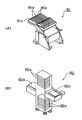
【0109】
ここで、部品実装基板生産装置401を構成している夫々の作業装置のうち代表として、第2作業装置420の模式的な斜視図を図18に示す。図18に示すように、第2作業装置420は、プラットホーム428を備えており、プラットホーム428の上面においては、第2作業装置420においてチップ部品装着工程Bを行うことを可能とする夫々の構成部材(以下に示す)が備えられている。
【0110】
まず、回路基板1の両端を支持しながら上記搬送経路沿いに回路基板1を搬送可能な第2搬送装置422の一対のレール422aが、プラットホーム428上に備えられた基板支持台425に支持されて備えられている。また、第2搬送装置422により搬送経路沿いに搬送されて第2作業位置421に解除可能に位置決めされて保持位置が固定された回路基板1に対して、上記所定の作業を行うヘッド部の一例であるチップ部品装着ヘッド部72が第2作業装置420に着脱可能に装備されている。また、第2作業装置420は、ヘッド部駆動装置の一例である第2XYロボット423を備えており、第2XYロボット423は、ヘッド部を着脱可能に取り付けることができるヘッド部取付部の一例である第2ヘッド部取付部423aを有し、かつ、第2ヘッド部取付部423aとともに、第2ヘッド部取付部423aに装備されたヘッド部、すなわち、チップ部品装着ヘッド部72を、図18の図示X軸方向に進退移動させるX軸ロボット423xと、上記X軸ロボット423xを図示Y軸方向に進退移動させるY軸ロボット423yとを備えている。
【0111】
また、第2作業装置420は、第2XYロボット423によるヘッド部(すなわち、チップ部品装着ヘッド部72)の移動動作、上記ヘッド部の動作、及び第2搬送装置422による回路基板1の搬送動作を制御するユニット制御部の一例である第2ユニット制御部424を備えており、また、第2ユニット制御部424の制御を一括して管理するとともに、他の作業装置との間の制御の調整(例えば、回路基板1の搬送・受渡し動作等の調整)を行う主制御部の一例である第2メイン制御部429を備えている。
【0112】
このように、第2作業装置420においては、第2ヘッド部取付部423aを有する第2XYロボット423と、第2搬送装置422と、第2ユニット制御部424と、第2メイン制御部429とがプラットホーム428に備えられており、このような構成が作業装置の共通的な構成、すなわちモジュールの共通構成となっている。上記第1実施形態においては、夫々のモジュールに2つずつのユニットが備えられているため、モジュールの共通構成についても、2組のXYロボットと、2組の搬送装置と、2組のユニット制御部とが備えられている点において、モジュールの共通構成として夫々1組ずつしか備えられていない本第2実施形態と異なっている。なお、第1作業装置410、第3作業装置430、及び第4作業装置440についても、夫々このモジュールの共通構成を有している。
【0113】
また、夫々の作業装置におけるヘッド部取付部の形状は共通化されており、複数の種類のヘッド部の中から選択された任意の1つのヘッド部を着脱可能に取り付けることが可能となっている。
【0114】
再び、図17に戻って、部品実装基板生産装置401について説明する。
【0115】
図17において詳細は図示しないが、上述したように夫々の作業装置において、上記第2作業装置420が備えるモジュールの共通構成と同様な構成が備えられている。また、第1作業装置410においては、塗布供給ヘッド部71が着脱可能に選択的に装備されており、これにより、第1作業装置410において、半田塗布供給工程Aを行うことが可能となっている。また、第3作業装置430においては、チップ部品装着ヘッド部72が着脱可能に選択的に装備されており、これにより、第3作業装置430において、チップ部品装着工程Cを行うことが可能となっている。また、第4作業装置440においては、IC部品接合ヘッド部73が着脱可能に選択的に装備されており、これにより、第4作業装置440において、IC部品接合工程Dを行うことが可能となっている。
【0116】
ここで、部品実装基板生産装置401における夫々の制御部の関係を示すブロック図を図19に示す。図19に示すように、第1作業装置410においては、第1XYロボットは第1XYロボット制御部413bを備え、また、塗布供給ヘッド部71は塗布供給ヘッド部制御部71aを備えており、さらに、第1XYロボット制御部413b及び塗布供給ヘッド部制御部71aは、第1メイン制御部419に第1ユニット制御部414を介して接続されている。同様に、第2作業装置420においては、第2XYロボットは第2XYロボット制御部423bを備え、また、チップ部品装着ヘッド部72はチップ部品装着ヘッド部制御部72aを備えており、さらに、第2XYロボット制御部423b及びチップ部品装着ヘッド部制御部72aは、第2メイン制御部429に第2ユニット制御部424を介して接続されている。同様に、第3作業装置430においては、第3XYロボットは第3XYロボット制御部433bを備え、また、チップ部品装着ヘッド部72はチップ部品装着ヘッド部制御部72aを備えており、さらに、第3XYロボット制御部433b及びチップ部品装着ヘッド部制御部72aは、第3メイン制御部439に第3ユニット制御部434を介して接続されている。第4作業装置440においては、第4XYロボットは第4XYロボット制御部443bを備え、また、IC部品接合ヘッド部73はIC部品接合ヘッド部制御部73aを備えており、さらに、第4XYロボット制御部443b及びIC部品接合ヘッド部制御部73aは、第4メイン制御部449に第4ユニット制御部444を介して接続されている。なお、夫々のメイン制御部、ユニット制御部、XYロボット制御部、及びヘッド部制御部における互いの制御的な関係は、上記第1実施形態において説明した制御関係(図16に基づいて説明)と同様であるため説明を省略する。
【0117】
また、図17において図示しないが、第2作業装置420及び第3作業装置430の夫々にはカセットフィーダ81が選択的に着脱可能に装備され、第4作業装置440にはトレイ供給部82が選択的に着脱可能に装備されている。また、図19に示すように、第2ユニット制御部424にはカセットフィーダ81に備えられている部品供給制御部81bが接続されており、第3ユニット制御部434にはカセットフィーダ81に備えられている部品供給制御部81bが接続されており、第4ユニット制御部444にはトレイ供給部82に備えられている部品供給制御部82bが接続されている。
【0118】
図19に示すように、夫々のヘッド部自体にヘッド部の制御を行うヘッド部制御部が個別に備えられているため、ヘッド部を作業装置から取り外すことによりヘッド部制御部とユニット制御部との接続を解除することができ、逆に、ヘッド部を作業装置に装備させることによりヘッド部制御部とユニット制御部とを接続することができる。同様に、カセットフィーダ81やトレイ供給部82等の部品供給部自体に部品供給部の制御を行う部品供給制御部が個別に備えられているため、部品供給部を作業装置から取り外すことにより部品供給制御部とユニット制御部との接続を解除することができ、逆に、部品供給部を作業装置に装備させることにより部品供給制御部とユニット制御部とを接続することができる。
【0119】
このような部品実装基板生産装置401において、夫々の作業装置にて行うことができる工程の変更を行う場合には、上記第1実施形態において説明した方法、すなわち、夫々の作業装置に選択的かつ着脱可能にヘッド部を交換装備させること、及び、夫々の作業装置に選択的かつ着脱可能に部品供給部を交換装備させることといった方法により、部品実装基板生産装置401の構成を容易に変更することができ、部品実装基板生産装置401において行うことができる工程の変更を容易に行うことができる。
【0120】
なお、上記においては部品実装基板生産装置401が上記モジュールの共通構成を備える複数の作業装置により形成されている場合について説明したが、本第2実施形態における部品実装基板生産装置はこのような場合に限定されるものではない。例えば、部品実装基板生産装置を構成する1台の作業装置が、上記モジュールの共通構成を備え、かつ、異なる種類のヘッド部及び部品供給部を交換可能に待機させて備えてさえいれば、上記1台の作業装置において、上記異なる種類のヘッド部を選択的にかつ着脱可能に交換装備させること、又は、上記異なる種類の部品供給部を選択的にかつ着脱可能に交換装備させることにより、上記1台の作業装置において行うことができる工程の変更を行うことができ、上記部品実装基板生産装置において行うことができる工程の変更が可能となる。
【0121】
さらに、上記のように部品実装基板生産装置が複数の作業装置により形成されている場合に代えて、1台の作業装置により部品実装基板生産装置が形成されている場合であってもよい。このような部品実装基板生産装置を、上記第2実施形態の変形例として以下に説明する。
【0122】
基板より部品実装基板を生産する場合にあっては、部品実装基板を生産するための複数の工程の夫々を行う複数の作業装置が連接されている場合が、基板の移動の要する時間が短く、かつ、基板の移動に要するコスト(搬送コスト等)の発生も少なくなり、最も効率良く部品実装基板の生産を行うことができるが、現実的には、上記複数の工程が異なる場所(異なる離れた場所)や異なるユーザーにおいて行われる場合がある。例えば、1台の作業装置のみが設置される場合であって、その1台の作業装置により、基板に対して塗布供給工程のみが行われる場合、あるいは、半田塗布供給工程のみが行われた基板に対してチップ部品装着工程のみが行われる場合があり、夫々において部品実装基板が生産される。しかしながら、上述のように複数の作業装置が連接された部品実装基板生産装置により部品実装基板の生産を行う場合が最も生産効率がよくなるのに対して、このように1台の作業装置のみにより部品実装基板を生産している理由の多くは、作業装置の設置場所が制約されて複数の作業装置を設置することができない、または、上記ユーザーにおける設備投資力により複数の作業装置を有することができないといったことである。このような問題点を本変形例により解決することが可能となる。
【0123】
まず、本変形例の部品実装基板生産装置は、例えば、図18に示す第2作業装置420により形成される。上述したように第2作業装置420は、上記モジュールの共通構成を備えている。さらに、複数の工程を行うための複数の種類のヘッド部として、塗布供給ヘッド部71とチップ部品装着ヘッド部72とを、交換装備可能に待機させて、第2作業装置420が備えている。
【0124】
これにより、第2作業装置420において半田塗布供給工程Aを行う場合にあっては、第2作業装置420の第2ヘッド部取付部423aに、上記待機させている塗布供給ヘッド部71を着脱可能に装備させることにより、供給される複数の回路基板1に対して半田塗布供給工程Aを行うことが可能となる。一方、上記第2作業装置420により半田塗布供給工程Aが施され、半田が供給形成された複数の回路基板に対して、チップ部品装着工程Bを行うような場合にあっては、まず、第2作業装置420において、第2ヘッド部取付部423aから塗布供給ヘッド部71を取り外して、その後、第2ヘッド部取付部423aに、上記待機させているチップ部品装着ヘッド部72を着脱可能に装備させることにより、上記複数の回路基板に対して、チップ部品装着工程Bを行い、部品実装基板を生産することができる。
【0125】
従って、このような部品実装基板を生産するユーザー等においては、上記1台の作業装置として第2作業装置420と、複数の工程を行うための複数の種類のヘッド部を交換待機させて備えていることにより、上記1台の作業装置に複数の種類のヘッド部を交換装備させて複数の工程を行うことができ、部品実装基板の生産において、複数の作業装置を有するために多額の設備投資を行うこともなく、また、複数の作業装置を設置するための広い設置場所を確保することもなく、1台の作業装置の設置場所を確保することのみで、上記部品実装基板の生産に効率的に対応することが可能となる。
【0126】
なお、上記においては、上記1台の作業装置に交換装備可能に待機して備えられるヘッド部が、塗布供給ヘッド部71及びチップ部品装着ヘッド部72である場合について説明したが、上記ヘッド部として、IC部品接合ヘッド部73やリフローヘッド部74等が備えられているような場合であってもよく、このような場合にあっては、上記1台の作業装置において行い得る工程をさらに多様化することができる。
【0127】
上記第2実施形態によれば、上記第1実施形態のように部品実装基板生産装置101を構成している夫々のモジュール(若しくは作業装置)が、基板の搬送経路沿いに直列的に配置された2つのユニットを備え、夫々のユニットにおいて複数の種類のヘッド部の中から1つのヘッド部を選択的にかつ着脱可能に装備させることができるような場合でなくても、部品実装基板生産装置401を構成している夫々の作業装置が1つのヘッド部しか装備することができないが、その装備させることができる上記1つのヘッド部が、複数の種類のヘッド部の中から選択的にかつ着脱可能に装備させることができることにより、上記夫々の作業装置において、適切なヘッド部を選択して着脱可能に装備させるだけで、上記夫々の作業装置において行うことができる工程の変更を容易に行うことができ、上記第1実施形態による効果と同様な効果を得ることができる。
【0128】
また、このような効果は、部品実装基板生産装置401の上記夫々の作業装置において、上記モジュールの共通構成としてメイン制御部及びユニット制御部等が備えられ、上記夫々の作業装置において選択的にかつ着脱可能に装備されるヘッド部の制御を行うヘッド部制御部が夫々のヘッド部自体に備えられていることにより実現可能となるものである。すなわち、従来の作業装置のように、ヘッド部の制御を行うヘッド部制御部が、上記ユニット制御部やメイン制御部に備えられて、異なる種類へのヘッド部の交換を試みようとしても、上記ヘッド部の交換が上記メイン制御部等の大幅な改造等を伴い、困難なものとなるというのではなく、上記作業装置において異なる種類のヘッド部を交換装備させるような場合であっても、上記メイン制御部等の構成の変更を伴うこともない。また、ヘッド部制御部がヘッド部自体に備えられていることにより、ヘッド部を装備させる場合に接続が必要な配線を少なくすることができ、ヘッド部の交換装備の作業を容易にすることができる。さらに、上記メイン制御部等に、上記ヘッド部制御部を備えさせないため、上記メイン制御部の構成をより簡単なものとすることができる。また、部品供給部についても、互いに異なる種類の制御を行う部品供給制御部が夫々の部品供給部自体に備えさせられているため、同様に、より様々な種類の部品供給部の装備にも対応することを可能とすることができる。従って、部品実装基板生産装置において様々な種類のヘッド部や部品供給部を容易に交換装備させることができ、部品実装基板の多品種小量生産により柔軟にかつ容易に対応することができる。
【0129】
また、部品実装基板を生産するユーザー等(すなわち、作業装置のユーザー等)においては、上記1台の作業装置として第2作業装置420と、複数の工程を行うための複数の種類のヘッド部を交換待機させて備えていることにより、上記1台の作業装置に複数の種類のヘッド部を交換装備させて複数の工程を行うことができ、部品実装基板の生産において、複数の作業装置を有するために多額の設備投資を行うこともなく、また、複数の作業装置を設置するための広い設置場所を確保することもなく、1台の作業装置の設置場所を確保することのみで、上記部品実装基板の生産に効率的に対応することが可能となる。
【0130】
<第3実施形態>
次に、本発明の第3実施形態にかかる部品実装基板生産装置は、上記第1実施形態の部品実装基板生産装置101と同じ構成となっており、部品実装基板生産装置101において部品実装位板を生産する際に、部品実装基板生産装置101において分散的に備えられたユニット制御部、ヘッド制御部、及びXYロボット制御部等の夫々の制御部を用いて行われる分散制御方法について説明する。
【0131】
部品実装基板生産装置101においては、上記第1実施形態において説明したように、図16に示すような構成の制御部が備えられている。図16に示すように、夫々のモジュール及びユニットにおいては同様な制御部の構成を有しており、これらのモジュール及びユニットを代表して、例えば、第1モジュール10の第2ユニット30について説明すると、第2XYロボット制御部33b、チップ部品装着ヘッド制御部72a、及び部品供給制御部81bの3つの制御部は、夫々第2ユニット制御部34に接続されており、上記3つの制御部の夫々の間において出入力される情報は、第1ユニット制御部24及び第2ユニット制御部34を統括した制御を行う第1メイン制御部12を介することなく、第2ユニット制御部34のみを介して上記情報を互いに出入力することができる。すなわち、上記3つの制御部間では、互いに第1メイン制御部12を介することなく会話(情報の出入力)ができるため、第1メイン制御部12を介さない分だけ情報の出入力に要する時間を短縮化することができ、迅速な情報の出入力を行うことが可能となる。このような特徴及びその効果、すなわち、このような分散制御の特徴及びその効果は部品実装基板生産装置101における夫々のモジュール及びユニットにおいて同様に行うことができる。
【0132】
次に、このような分散制御の特徴及びその効果を利用した部品実装基板生産装置101における部品実装基板の生産における制御方法について説明する。
【0133】
部品実装基板の生産においては、アーチモーションと呼ばれる制御方法が用いられ、効率的な電子部品の装着動作が行われている。このアーチモーションが、第1モジュール10の第2ユニット30にて行われるチップ部品装着工程Bにおいて行われる場合を例として、アーチモーションについて、図20の第2XYロボット33とチップ部品装着ヘッド部72の吸着ノズル72bの動作関係を示すタイムチャートを用いて説明する。
【0134】
図20において、縦軸上側に第2XYロボット33の動作(移動/停止)を示し、縦軸下側に昇降装置72cによる吸着ノズル72bの昇降動作による吸着ノズル72bの先端高さ位置を示す。高さ位置H2は吸着ノズル72bの昇降動作の上端高さ位置であり、H0は吸着ノズル72bにより吸着保持されたチップ部品2が回路基板1に装着される際の装着高さ位置であり、H1は高さ位置H0とH2の間の高さであって、かつ吸着ノズル72bがチップ部品2を吸着保持した状態で第2XYロボット33によりX軸方向又はY軸方向に移動されるような場合であっても、回路基板1に先に装着されたチップ部品2等に吸着ノズル72b及び吸着保持されたチップ部品2が干渉しないような高さ位置である。また、図20における横軸は時間軸となっており、時間T0〜T7は吸着ノズル72bの動作に関する時間を示し、時間T13及びT16は第2XYロボット33の動作に関する時間を示す。
【0135】
図20に示すように、時間区分T0〜T1において、チップ部品2を吸着保持した吸着ノズル72bがその先端の高さ位置をH2とされた状態で、チップ部品装着ヘッド部72が第2XYロボット33により、回路基板1のチップ部品2の装着位置の上方を目標位置としてX軸方向又はY軸方向に移動(以降、XY移動とする)される。時間T1において、上記XY移動が行われながら、チップ部品装着ヘッド部72において、昇降装置72cにより吸着ノズル72bの下降動作が開始され、時間T2においてその先端高さがH1とされ、上記下降動作が停止される。その後、時間T13において、第2XYロボット33の上記XY移動により吸着ノズル72bが上記回路基板1の上方の上記目標位置に達されて、上記XY移動が停止される。されとともに、第2XYロボット制御部33bより上記目標位置へのXY移動の完了情報が出力されて、この情報が第2ユニット制御部34に入力される。第2ユニット制御部34においては、この入力された情報の出力先の判断が行われ、この情報がチップ部品装着ヘッド部制御部72aへ出力される。チップ部品装着ヘッド部制御部72aにおいて、この入力された情報に基づき、昇降装置72cによる吸着ノズル72bの下降動作を開始させる。このタイミングが時間T3である。時間T3において高さ位置H1から下降動作が開始された吸着ノズル72bは、時間T4において高さ位置H0とされて、吸着保持されているチップ部品2が回路基板1の上記装着位置に当接され、チップ部品2が回路基板1に装着される。
【0136】
その後、時間T5において、吸着ノズル72bはチップ部品2の吸着保持を解除するとともに、昇降装置72cにより高さ位置H2に向けて上昇動作が開始される。時間T6において、上記上昇動作が行われている吸着ノズル72bの先端高さ位置がH1に達したときに、チップ部品装着ヘッド部制御部72aよりXY移動が可能となったことの情報が出力されて、第2ユニット制御部34に入力される。第2ユニット制御部34においては、この入力された情報の出力先の判断が行われ、この情報が第2XYロボット制御部33bに出力される。第2XYロボット制御部33bにおいて、この情報に基づいて、第2XYロボット33によりチップ部品装着ヘッド部72のXY移動が開始される。このタイミングが時間T16である。このとき、吸着ノズル72bの先端高さ位置がH1よりも高い位置に位置されているため、上記XY移動によっても吸着ノズル72bが回路基板1に装着されているチップ部品2等に干渉することはない。その後、上記XY移動が行われながら、昇降装置72cによる吸着ノズル72bも上昇されて、時間T7において高さH2に達し、上記上昇動作が停止される。複数のチップ部品2が回路基板1に装着される場合にあっては、上記と同様な動作が順次繰り返して行われる。
【0137】
このようなアーチモーションの動作においては、第2XYロボット制御部33bとチップ部品装着ヘッド部制御部72aとの間で、情報の受渡し(出入力)が行われ、夫々入力された情報に基づいて関連された動作が行われる。第2XYロボットによる上記目標位置への吸着ノズル72bの移動が完了したことの情報は、時間T13において第2XYロボット制御部33bより出力され、時間T3において、入力された上記情報に基づいてチップ部品装着ヘッド部制御部72aにより吸着ノズル72bの下降動作が開始される。つまり、上記XY移動の完了から、吸着ノズル72bの下降動作開始までの間には、時間ロス(時間T3−T13)があることとなる。同様に、チップ部品2の装着後、吸着ノズル72bが上昇されて高さ位置H1に達したことの情報が、時間T6においてチップ部品装着ヘッド部制御部72aより出力され、時間T16において、入力された上記情報に基づいて第2XYロボット制御部33bによりXY移動が開始される。つまり、上記高さ位置H1への到達から、XY移動の開始までの間には、時間ロス(時間T16−T6)があることになる。
【0138】
しかしながら、部品実装基板生産装置101においては、上述したように分散制御が行われているため、第2XYロボット制御部33bとチップ部品装着ヘッド部制御部72bとの間の情報の受渡しは第2ユニット制御部34を介するのみで、第1メイン制御部12を介することはない。そのため、第2XYロボット制御部33bとチップ部品装着ヘッド部制御部72bとの間の情報の受け渡しに要する時間は、メイン制御部を介して情報の受渡しが行われる場合と比べて短くすることができる。従って、上記時間ロス(時間T3−T13、時間T16−T6)を短くすることができ、これにより、第2XYロボット33によるXY移動の停止時間を短縮化することができ、アーチモーションの高速化を図ることができる。
【0139】
なお、上記においては、第2ユニット30におけるチップ部品装着工程Bにおける場合を例として説明したが、夫々のユニットにおいてXYロボット制御部、ヘッド部制御部、及び部品供給制御部の夫々の間の情報の受渡しに要する時間を短縮できるため、夫々のユニットにおいて行われる工程においても同様に、アーチモーションの高速化を図ることができる。
【0140】
また、上記分散制御の特徴としては、夫々のユニットに着脱可能に装備可能なヘッド部自体に、上記ヘッド部の動作制御を行うヘッド部制御部が備えられており、上記ユニットに着脱可能に装備された上記ヘッド部を取り外した場合には、上記ヘッド部とともに上記ヘッド部制御部も取り外すことができるという点がある。このような特徴を利用すれば、例えば、上記ユニットから取り外されたヘッド部をヘッド部単体としての動作確認等のテストを行うことができる。
【0141】
例えば、上記ユニットへの装備前の状態のヘッド部のヘッド部制御部による動作確認等のテストを行うことにより、上記ヘッド部が上記ユニットに着脱可能に装備されて所定の工程が行われるような場合に、確実なヘッド部の動作を行うことができる。また、上記ヘッド部の定期的なメンテナンスとしての動作確認を行うような場合にあっては、上記ユニットから上記ヘッド部を取り外した状態で上記動作確認等のテストを行うことができるため、このような上記ヘッド部のテストを行っている間は、上記ユニットに別のヘッド部を着脱可能に装備させれば、上記ユニットにおいて所定の工程を行うことができる。従って、上記メンテナンス性を向上させるとともに、確実な上記動作確認等のテストを行うことができ、安定した動作を行うことができ、ヘッド部の動作の信頼性を向上させることができる。
【0142】
なお、本第3実施形態においては、上記第1実施形態における部品実装基板生産装置101を基に、上記アーチモーションの動作について説明したが、上記第2実施形態の部品実装基板生産装置401においても、上記と同様な動作を行うことが可能である。
【0143】
上記第3実施形態によれば、モジュールにおいて、夫々のユニットにおける作業の動作制御を行うメイン制御部が備えられ、夫々のユニットにおいて、XYロボット制御部がXYロボットに、ヘッド部制御部がヘッド部に、部品供給制御部が部品供給部に夫々備えられ、さらに、上記XYロボット制御部、ヘッド部制御部、及び部品供給制御部の夫々の間の情報の受渡しを行い、かつ、メイン制御部に接続されたユニット制御部が備えられていることにより、上記XYロボット制御部、ヘッド部制御部、及び部品供給制御部の夫々の間の情報の受渡しの際に、上記情報をメイン制御部を介さずに、ユニット制御部のみを介して行うことができる。これにより、夫々の工程における所定の作業が行われる際に頻繁に行われる上記情報の受け渡しを行うための負担を統括的な制御を行うメイン制御部に掛けることなく、上記XYロボット制御部、ヘッド部制御部、及び部品供給制御部の夫々に直接接続されているユニット制御部のみを介して行うことができるため、メイン制御部を介して情報の受渡しを行う場合と比べて、効率的な上記情報の受渡しを行うことができ、部品実装基板生産装置における部品実装基板の生産に要する時間を短縮化することができ、より効率的な部品実装基板の生産を行うことができる。
【0144】
また、上記分散制御の特徴としては、夫々のユニットに着脱可能に装備可能なヘッド部自体に、上記ヘッド部の動作制御を行うヘッド部制御部が備えられており、上記ユニットに着脱可能に装備された上記ヘッド部を取り外した場合には、上記ヘッド部とともに上記ヘッド部制御部も取り外すことができるという点がある。このような特徴を利用すれば、例えば、上記ユニットから取り外されたヘッド部をヘッド部単体としての動作確認等のテストを行うことができる。
【0145】
例えば、上記ユニットへの装備前の状態のヘッド部のヘッド部制御部による動作確認等のテストを行うことにより、上記ヘッド部が上記ユニットに着脱可能に装備されて所定の工程が行われるような場合に、確実なヘッド部の動作を行うことができる。また、上記ヘッド部の定期的なメンテナンスとしての動作確認を行うような場合にあっては、上記ユニットから上記ヘッド部を取り外した状態で上記動作確認等のテストを行うことができるため、このような上記ヘッド部のテストを行っている間は、上記ユニットに別のヘッド部を着脱可能に装備させれば、上記ユニットにおいて所定の工程を行うことができる。従って、上記メンテナンス性を向上させるとともに、確実な上記動作確認等のテストを行うことができ、安定した動作を行うことができ、ヘッド部の動作の信頼性を向上させることができる。また、このような効果は、ヘッド部と同様に夫々のユニットに着脱可能に装備させることができる部品供給部等についても同様である。
【0146】
なお、上記様々な実施形態のうちの任意の実施形態を適宜組み合わせることにより、それぞれの有する効果を奏するようにすることができる。
【0147】
【発明の効果】
本発明の上記第1態様又は第2態様によれば、部品実装基板を生産するときの複数の工程のうちの少なくとも1つの工程を行う作業装置が、基板に対して複数の工程を行うための複数の種類のヘッド部の中から選択された1つのヘッド部と、上記選択された1つのヘッド部を着脱可能に取り付けるヘッド部取付部を有し、かつ、上記ヘッド部取付部に着脱可能に取り付けられた上記1つのヘッド部を少なくとも基板搬送方向と直交する方向と上記基板搬送方向とに移動可能なヘッド部駆動装置とを備えているため、上記作業装置において、上記複数の種類のヘッド部の中から別の1つのヘッド部を選択して、上記ヘッド部取付部に着脱可能に取り付けられた上記1つのヘッド部を取り外すとともに、上記1つのヘッド部に代えて、上記別の1つのヘッド部を取り付けることにより、取り付けられた上記別の1つのヘッド部に応じた工程を行うことが可能となる。
【0148】
すなわち、従来の部品実装基板生産装置が備える作業装置のように、上記作業装置において行われる工程のみを行うために必要な構成が上記作業装置において個別にかつ変更不可能に備えられているのではなく、上記作業装置においては、常設された構成(変更不可能に常設された構成)である上記ヘッド部駆動装置と、変更可能な最小限の構成である上記ヘッド部とが備えられ、上記常設された構成(すなわち上記ヘッド部駆動装置)に上記変更可能な構成(すなわち上記ヘッド部)を選択的にかつ着脱可能に装備させることを可能としている。
【0149】
従って、部品実装基板を生産するユーザー等(すなわち、作業装置のユーザー等)においては、1台の上記作業装置と、複数の工程を行うための複数の種類のヘッド部を交換待機させて備えていることにより、上記1台の作業装置に複数の種類のヘッド部を順次交換装備させて複数の工程を行うことができる。よって、部品実装基板の生産において、複数の作業装置を有するために多額の設備投資を行うこともなく、また、複数の作業装置を設置するための広い設置場所を確保することもなく、1台の上記作業装置の設置場所を確保することのみで、上記部品実装基板の生産に効率的に対応することが可能となる。
【0150】
また、このような効果は、上記作業装置において、上記常設された構成として主制御部及びユニット制御部等が備えられ、上記作業装置において選択的にかつ着脱可能に装備されるヘッド部の制御を行うヘッド部制御部が夫々のヘッド部自体に備えられていることにより実現可能となるものである。すなわち、従来の作業装置のように、ヘッド部の制御を行うヘッド部制御部が、上記ユニット制御部や上記主制御部に備えられて、異なる種類のヘッド部への交換を試みようとしても、上記ヘッド部の交換が上記主制御部等の大幅な改造等を伴い、困難なものとなるというのではなく、上記作業装置において異なる種類のヘッド部を交換装備させるような場合であっても、上記メイン制御部等の構成の変更を伴うこともない。また、上記ヘッド部制御部がヘッド部自体に備えられていることにより、ヘッド部を装備させる場合に接続が必要な配線を少なくすることができ、ヘッド部の交換装備の作業を容易にすることができる。さらに、上記主制御部等に、上記ヘッド部制御部を備えさせないため、上記主制御部の構成をより簡単なものとすることができる。従って、部品実装基板生産装置において様々な種類のヘッド部や部品供給部を容易に交換装備させることができ、部品実装基板の多品種小量生産により柔軟にかつ容易に対応することができる。
【0151】
また、上記ユニット制御部は、上記ヘッド部制御部による上記ヘッド部の制御と、上記ヘッド部駆動装置に備えられかつ上記ヘッド部駆動装置の動作制御を行う駆動装置制御部による上記ヘッド部駆動装置の制御とについて、上記主制御部による制御と上記主制御部とは無関係の制御とを選択して実施させることができるため、上記主制御部とは無関係の制御、例えば、上記ヘッド部制御部から上記ヘッド部駆動装置に受け渡される情報を、上記主制御部を介するのではなく、上記ユニット制御部のみを介して受け渡すことができる。従って、部品実装基板が生産させる際に頻繁に行われるこのような情報の受渡しを、上記主制御部を介して上記情報の受渡しを行う場合と比べて、より効率的に行うことができ、部品実装基板の生産に要する時間を短縮化することができ、効率的な生産を行うことができる部品実装基板生産装置を提供することができる。
【0152】
また、上記ヘッド部自体に、上記ヘッド部の動作制御を行う上記ヘッド部制御部が備えられており、上記作業装置に着脱可能に装備された上記ヘッド部を取り外した場合には、上記ヘッド部とともに上記ヘッド部制御部も取り外すことができるため、例えば、上記作業装置から取り外された上記ヘッド部を上記ヘッド部単体としての動作確認等のテストを行うことができる。例えば、上記作業装置への装備前の状態の上記ヘッド部の上記ヘッド部制御部による動作確認等のテストを行うことにより、上記ヘッド部が上記作業装置に着脱可能に装備されて所定の工程が行われるような場合に、確実なヘッド部の動作を行うことができる。また、上記ヘッド部の定期的なメンテナンスとしての動作確認を行うような場合にあっては、上記作業装置から上記ヘッド部を取り外した状態で上記動作確認等のテストを行うことができるため、このような上記ヘッド部のテストを行っている間は、上記作業装置に別のヘッド部を着脱可能に装備させれば、上記作業装置において所定の工程を行うことができる。従って、部品実装基板生産装置において上記ヘッド部のメンテナンス等のための生産停止時間を短縮化させて効率的な生産を行うことができるとともに、確実な上記動作確認等のテストを行うことができ、安定した動作を行うことができ、ヘッド部の動作の信頼性、すなわち部品時層基板生産装置の信頼性を向上させることができる。
【0153】
本発明の上記第3態様によれば、上記作業装置が、上記部品実装基板を生産するときの連続した複数の工程を上記基板の搬送経路における複数の作業位置において行う複数の作業装置のうちの少なくとも1つの作業装置であることにより、部品実装基板生産装置において生産される部品実装基板の機種変更等により部品実装基板生産装置において行われる工程の変更が必要となるような場合であっても、従来のように上記作業装置の入替え設置等を行う必要がなく、上記作業装置において、上記常設された構成に上記変更可能な構成を選択的にかつ着脱可能に装備させる、つまり、上記複数の種類のヘッド部の中から行われる工程に応じた適切な1つのヘッド部を選択して着脱可能に上記ヘッド部駆動装置の上記ヘッド部取付部に装備させるだけで、上記作業装置における上記常設された構成を変更することなく、上記作業装置において行うことができる工程の変更を容易に行うことができる。よって、部品実装基板生産装置において、工程の変更や拡張が必要な場合であっても、上記工程の変更や拡張に容易に対応することができ、生産される部品実装基板の機種変更に対しても容易かつ柔軟に対応することができ、さらに、多品種少量生産にも効果的に対応することができる。
【0154】
また、部品実装基板生産装置における上記工程の変更等にあたっては、上記工程の変更が行われる上記1つの作業装置自体を交換することもなく、かつ、上記1つの作業装置が有する上記常設された構成を変更することもなく、上記変更可能な構成である上記ヘッド部のみを上記工程に合わせて選択的に交換することにより上記工程の変更に対応することができる。そのため、このような部品実装基板生産装置のユーザーから見れば、部品実装基板の多品種少量生産等に対応するために、1つの種類の部品実装基板の生産に同時に用いられない複数種類の作業装置を保有しておくこともなく、複数種類のヘッド部を保有してさえいれば、上記対応を行うことができる。よって、部品実装基板の多品種少量生産に対応するための生産設備に対する設備投資を抑制することができ、部品実装基板の生産コストを削減することができる。
【0155】
また、上記部品実装基板の多品種少量生産に対応するために、全ての種類の部品実装基板の生産に対応できる複数台若しくは複数種類の作業装置を部品実装基板生産装置に備えさせる必要も無くすことができ、単に上記ヘッド部の交換、すなわち、上記常設された構成に対して上記変更可能な構成を選択的にかつ着脱可能に装備させることでもって対応することができる。これにより、夫々の作業装置の稼動効率を低下させたり、部品実装基板生産装置の設置長さが長くなるといった問題を防止し、部品実装基板生産装置の設置長さを短縮化して、部品実装基板の単位面積当りの生産性を向上させることができる。
【0156】
本発明の第4態様によれば、上記夫々の態様による効果に加えてさらに、上記ヘッド部自体に上記ヘッド部制御部が備えられ、上記1つの作業装置において、上記ヘッド部を上記ヘッド部取付部に着脱可能に取り付けることにより、上記ヘッド部制御部が接続解除可能に上記ユニット制御部に接続され、かつ、上記ヘッド部を上記ヘッド部取付部から取り外すことにより、上記ヘッド部制御部と上記ユニット制御部との接続が解除されるように構成されていることにより、上記1つの作業装置への上記ヘッド部の交換装備をより容易に行うことができ、部品実装基板生産装置における工程の変更にも容易に対応することができる。
【0157】
本発明の第5態様によれば、上記夫々の態様による効果に加えてさらに、上記複数の種類のヘッド部として、接合材供給用ノズルを有する接合材供給ヘッド部と、部品装着用ノズルを有する部品装着ヘッド部とを含み、上記1つの作業装置において、上記複数の種類のヘッド部の中から上記接合材供給ヘッド部を選択して着脱可能に装備させることにより、上記基板に接合材を供給する接合材供給工程を行うことができ、また、上記1つの作業装置において、上記複数の種類のヘッド部の中から上記部品装着ヘッド部を選択して着脱可能に装備させることにより、上記基板に供給された上記接合材を介して上記部品を装着する部品装着工程とを行うことができる。すなわち、上記夫々のヘッド部の選択装備により、上記接合材供給工程又は上記部品装着工程を行い得る部品実装基板生産装置を提供することができる。
【0158】
本発明の第6態様によれば、上記夫々の態様による効果に加えてさらに、上記複数の種類のヘッド部は、チップ部品装着ヘッド部、IC部品装着ヘッド部、IC部品接合ヘッド部、マルチノズルヘッド部、塗布供給ヘッド部、又はリフローヘッド部のいずれかを含んでいることにより、上記夫々のヘッド部の機能に応じた工程を、上記夫々のヘッド部が選択されて装備された上記1つの作業装置において行うことができるため、より様々な種類の工程を行うことができ、より多様な種類の部品実装基板の生産に対応することができる部品実装基板生産装置を提供することができる。
【図面の簡単な説明】
【図1】 本発明の第1実施形態にかかる部品実装基板生産装置の模式的な構成を示す模式斜視図である。
【図2】 上記第1実施形態の部品実装基板生産装置が備える第1モジュールの模式的な構成を示す模式斜視図である。
【図3】 上記第1実施形態の上記第1モジュールにおける制御部の構成を示すブロック図である。
【図4】 上記第1実施形態の部品実装基板生産装置に装備されるヘッド部の模式斜視図であり、(A)はチップ部品装着ヘッド部、(B)はIC部品接合ヘッド部、(C)は塗布供給ヘッド部である。
【図5】 上記第1実施形態の部品実装基板生産装置に装備される塗布供給ヘッド部の斜視図である。
【図6】 上記第1実施形態の部品実装基板生産装置に装備される部品供給部の模式斜視図であり、(A)はカセットフィーダ、(B)はトレイ供給部である。
【図7】 上記第1実施形態の部品実装基板生産装置において行われる部品実装基板の生産工程をチップ部品、及び回路基板の模式的な断面図を用いて説明する説明図であり、(A)及び(B)は半田塗布供給工程であり、(C)及び(D)はチップ部品装着工程である。
【図8】 上記第1実施形態の部品実装基板生産装置において行われる部品実装基板の生産工程をチップ部品、IC部品、及び回路基板の模式的な断面図を用いて説明する説明図であり、(E)及び(F)はチップ部品装着工程であり、(G)及び(H)はIC部品接合工程である。
【図9】 上記第1実施形態の部品実装基板生産装置の構成形態を模式的に示す模式平面図である。
【図10】 上記第1実施形態の部品実装基板生産装置の構成形態を模式的に示す模式斜視図であり、第2モジュールにおいてヘッド部及び部品供給部が取り外された状態の部品実装基板生産装置を示す。
【図11】 上記第1実施形態の部品実装基板生産装置の構成形態を模式的に示す模式斜視図であり、第2モジュールにおいてヘッド部及び部品供給部が交換されて工程の変更が行われた状態の部品実装基板生産装置を示す。
【図12】 上記第1実施形態の部品実装基板生産装置に装備されるリフローヘッド部の模式斜視図である。
【図13】 上記第1実施形態の上記工程の変更が行われた部品実装基板生産装置において行われる部品実装基板の生産工程をチップ部品、及び回路基板の模式的な断面図を用いて説明する説明図であり、(A)及び(B)は半田塗布供給工程であり、(C)及び(D)はチップ部品装着工程である。
【図14】 上記第1実施形態の上記工程の変更が行われた部品実装基板生産装置において行われる部品実装基板の生産工程をチップ部品、IC部品、及び回路基板の模式的な断面図を用いて説明する説明図であり、(E)及び(F)はIC部品接合工程であり、(G)及び(H)はリフロー工程である。
【図15】 図1の部品実装基板生産装置の構成を模式的に示す模式平面図である。
【図16】 上記第1実施形態の部品実装基板生産装置における制御部の構成を示すブロック図である。
【図17】 本発明の第2実施形態にかかる部品実装基板生産装置の模式的な構成を示す模式平面図である。
【図18】 上記第2実施形態の部品実装基板生産装置が備える第2作業装置の模式斜視図である。
【図19】 上記第2実施形態の部品実装基板生産装置における制御部の構成を示すブロック図である。
【図20】 本発明の第3実施形態にかかる部品実装基板生産装置において行われるアーチモーションの動作を示すタイムチャートである。
【図21】 従来の部品実装基板生産装置の模式斜視図である。
【符号の説明】
1…回路基板、1a…電極、1b…電極、1c…電極、2…チップ部品、2a…電極、3…IC部品、3a…電極、3b…バンプ、4…半田部、10…第1モジュール、11…プラットホーム、12…第1メイン制御部、20…第1ユニット、21…第1作業位置、22…第1搬送装置、22a…レール、23…第1XYロボット、23a…第1ヘッド部取付部、23b…第1XYロボット制御部、24…第1ユニット制御部、30…第2ユニット、31…第2作業位置、32…第2搬送装置、32a…レール、33…第2XYロボット、33a…第2ヘッド部取付部、33b…第2XYロボット制御部、34…第2ユニット制御部、40…第2モジュール、41…プラットホーム、42…第2メイン制御部、50…第1ユニット、51…第1作業位置、52…第1搬送装置、53…第1XYロボット、53a…第1ヘッド部取付部、53b…第1XYロボット制御部、54…第1ユニット制御部、60…第2ユニット、61…第2作業位置、62…第2搬送装置、63…第2XYロボット、63a…第2ヘッド部取付部、63b…第2XYロボット制御部、64…第2ユニット制御部、71…塗布供給ヘッド部、71a…塗布供給ヘッド部制御部、71b…塗布ノズル、71c…昇降装置、71d…取付部、71e…半田供給部、71f…撮像カメラ、71g…ボルト取付穴、71h…位置決めピン穴、72…チップ部品装着ヘッド部、72a…チップ部品装着ヘッド部制御部、72b…吸着ノズル、72c…昇降装置、72d…取付部、73…IC部品接合ヘッド部、73a…IC部品接合ヘッド部制御部、73b…吸着ノズル、73c…昇降装置、73d…取付部、74…リフローヘッド部、81…カセットフィーダ、81a…部品供給カセット、82…トレイ供給部、82a…トレイ、101及び102…部品実装基板生産装置、401…部品実装基板生産装置、410…第1作業装置、411…第1作業位置、412…第1搬送装置、413b…第1XYロボット制御部、414…第1ユニット制御部、419…第1メイン制御部、420…第2作業装置、421…第2作業位置、422…第2搬送装置、422a…レール、423…第2XYロボット、423a…第2ヘッド部取付部、423b…第2XYロボット制御部、424…第2ユニット制御部、429…第2メイン制御部、430…第3作業装置、431…第3作業位置、432…第3搬送装置、433b…第3XYロボット制御部、434…第3ユニット制御部、439…第3メイン制御部、440…第4作業装置、441…第4作業位置、442…第4搬送装置、443b…第4XYロボット制御部、444…第4ユニット制御部、449…第4メイン制御部。[0001]
BACKGROUND OF THE INVENTION
The present invention relates to a component mounting board production apparatus including a working device that performs at least one of a plurality of processes when producing a component mounting board having components mounted on a board.
[0002]
[Prior art]
Conventionally, this type of component mounting board production apparatus has various structures. For example, as shown in FIG. 21, a conventional component mounting
[0003]
In FIG. 21, the component mounting
[0004]
In the case of producing a component mounting board in such a mounting
[0005]
[Problems to be solved by the invention]
A component mounting board produced by mounting an electronic component on a board has an electronic circuit formed therein, and is used for various types of electronic devices in which the electronic circuit is built. In addition, the current status of high-mix low-volume production is no exception for these various types of electronic devices. It is necessary to cope with a small amount of production, and it is desired to be able to flexibly and quickly cope with the model switching of the component mounting board produced in the component mounting board production apparatus. In the conventional component mounting
[0006]
In addition, there is a limit to the chip component mounting processing capacity (processing quantity and types of compatible parts, etc., the same applies hereinafter) by one chip
[0007]
In order to allow the operations required in the component mounting
[0008]
However, each work device often has a different length in the direction along the conveyance line of the board. For example, in the component mounting
[0009]
On the other hand, in order to solve the problem that it is not easy to replace and install such work devices, a plurality of units or a plurality of types that can handle all types of component mounting boards produced by the component mounting
[0010]
However, in such a case, the length of the component mounting
[0011]
Furthermore, in any of the above methods, when viewed from the side of producing a component mounting board by such a component mounting board production apparatus 501 (that is, the user side of the component mounting board production apparatus), If you do not have work equipment as production equipment, you will not be able to handle the above-mentioned high-mix low-volume production, and the capital investment for production equipment will increase, which will be a major factor that hinders the reduction of production costs for component mounting boards. There is a point.
[0012]
Accordingly, an object of the present invention is to solve the above-described problem, and mount a component on the substrate to produce a component mounting substrate while transporting the substrate through a plurality of continuous processes. In the board production equipment, the above-mentioned process can be easily changed, and it is possible to effectively cope with small-lot production of various products. Furthermore, the installation length can be shortened, and the unit mounting area can be reduced. An object of the present invention is to provide a component mounting board production apparatus capable of improving the productivity.
[0013]
[Means for Solving the Problems]
In order to achieve the above object, the present invention is configured as follows.
[0014]
According to the first aspect of the present invention, in the working device that performs at least one step among a plurality of steps when producing a component mounting board on which a component is mounted on a board at a work position in the board transport path,
One head unit selected from a plurality of types of head units for performing the plurality of steps on the substrate at the work position;
A head unit driving device having a head unit mounting portion that is movable in at least a direction orthogonal to the substrate transport direction and the substrate transport direction and has the selected one head unit removably attached thereto;
The head unit includes a head unit control unit capable of controlling the operation of the head unit,
The head unit driving device includes a driving device control unit capable of controlling the operation of the head unit driving device,
Furthermore, the working device includes:
A main control unit for controlling the operation of a plurality of works on the work device;
For the control of the head unit by the head unit control unit and the control of the head unit drive device by the drive device control unit, the control by the main control unit and the control independent of the main control unit are selectively performed. A component mounting board production apparatus comprising: a unit control unit for causing a component mounting board to be provided.
[0015]
According to the second aspect of the present invention, the working device includes a head portion of a different type from the one head portion of the plurality of types of remaining head portions from which the one head portion is selected. Further waiting to be able to be attached to the head part attachment part,
The head unit driving device provides the component mounting board production apparatus according to the first aspect, in which the selected one head unit is detachably and detachably attached to the other type of the head unit that has been waiting. .
[0016]
According to a third aspect of the present invention, the working device performs at least one of a plurality of working devices that perform a plurality of continuous steps when producing the component mounting board at a plurality of work positions in a transport path of the board. A component-mounting board production apparatus according to the first aspect or the second aspect, which is one work apparatus, is provided.
[0017]
According to the fourth aspect of the present invention, the head unit is removably attached to the head unit attaching part, so that the head part control unit is releasably connected to the unit control part, and the head part is The component mounting board production apparatus according to any one of the first to third aspects is provided in which the connection between the head part control part and the unit control part is released by removing the head part attachment part.
[0018]
According to the fifth aspect of the present invention, the plurality of steps include a bonding material supply step for supplying a bonding material to the substrate, and a component mounting step for mounting the component via the bonding material supplied to the substrate. Including
The plurality of types of head units according to any one of the first to fourth modes, including a bonding material supply head unit having a bonding material supply nozzle and a component mounting head unit having a component mounting nozzle. A component mounting board production apparatus is provided.
[0019]
According to the sixth aspect of the present invention, the plurality of types of head portions include a chip component mounting head portion, an IC component mounting head portion, an IC component bonding head portion, a multi-nozzle head portion, a coating supply head portion, or a reflow head. A component-mounting board production apparatus according to any one of the first to fifth aspects including any one of the units is provided.
[0020]
DETAILED DESCRIPTION OF THE INVENTION
In describing the embodiments of the present invention, the concept of the component mounting board production apparatus according to the present invention will be described first.
[0021]
<Component mounting board production equipment>
The process of producing a component mounting board by mounting a plurality of types of components on the board while transporting the board in the transport path (referred to as a component mounting board production process) is performed in a plurality of processes, for example, on the electrodes of the board. A bonding material supply step for supplying a bonding material (for example, solder, cream solder, conductive adhesive, etc.) for bonding electrodes to the electrode of the substrate by coating or the like, and a substrate on which the bonding material has been supplied The component mounting process for mounting the electrode of the component to the electrode of the component, the reflow process for mounting the component on the substrate by reflowing the bonding material on the substrate in a state where the component is mounted via the bonding material, etc. Is provided. Each of the processes constituting the component mounting board production process has a work position on the transport path, and a predetermined work can be performed on the board that is transported and supplied at the work position. it can.
[0022]
In the present specification, individual means for performing the above-described predetermined work at the predetermined work position on the substrate supplied in each step is functionally provided to perform the above-described process. Is a “unit”, and by connecting a plurality of units along the substrate transport path, the component mounting board production process can be performed in the plurality of connected units. For example, in a unit that can perform a bonding material supply step, a bonding material supply unit (for example, a solder application supply head that supplies and supplies cream solder to a substrate) that supplies the bonding material, or the above-described bonding material supply A driving unit (for example, an XY robot) that moves the unit, a substrate holding unit that holds the substrate at the work position, and the like are provided. As described above, since the unit includes the bonding material supply unit, the drive unit, the substrate holding unit, and the like, in the unit, the predetermined supply with respect to the substrate supplied to the working position is performed. As an operation, it is possible to supply a bonding material, that is, a bonding material supply process.
[0023]
On the other hand, in the present specification, the “component mounting board production device” includes a working device that performs the component mounting board production process, that is, at least one of the plurality of processes. This includes both cases where the apparatus is configured by installing only one unit, or cases where the unit is configured by connecting a plurality of such work apparatuses. Here, the “working apparatus” is an independent apparatus having one gantry, and an apparatus that performs one component mounting board production process. The working device includes one or more units on the one frame. That is, in the working device, the one or more units are included on the one frame (the two or more units described above). The unit is shared (or shared) and provided on the above-mentioned one frame). In addition, by installing a single work device or connecting a plurality of work devices along the substrate transfer path, the units included in the respective work devices are located along the substrate transfer route. A component mounting board production apparatus that is arranged in series and capable of performing a component mounting board production process is formed. When the component mounting board production apparatus is formed by only the one working apparatus, the one working apparatus becomes the component mounting board production apparatus as it is. The work device is also referred to as a “module”.
[0024]
In the present specification, the “component mounting board” means a board in which a plurality of components are mounted on the board. That is, the substrate in which the plurality of components are mounted on the substrate, and the respective components are mounted on the substrate so that they can be joined by performing the reflow before the reflow and in a subsequent process. To do. In addition, the case where it says the board | substrate after the said reflow, ie, the state in which the said some component was joined by reflow, may be used. Alternatively, pre-processing (for example, supply processing of a bonding material to the substrate) for mounting the component on the substrate is performed, and the substrate including the component that can be mounted on the substrate is included. And
[0025]
In this specification, “mounting” means a bonded state in which the component and the substrate can be easily separated without applying any external force to the component or the substrate, without destroying the component and the substrate. The term “bonded” refers to a bonded state in which the component and the substrate cannot be easily separated by applying an external force to the component or the substrate. ) Refers to the joined state. The state in which the component is “joined” to the board is also referred to as “mounting”.
[0026]
The “component” includes an electronic component, a mechanical component, an optical component, and the like, and examples of the electronic component include a chip component (such as a resistor and a capacitor) and an IC component.
[0027]
“Substrate” means a circuit board such as a resin board, a paper-phenol board, a ceramic board, a glass / epoxy (glass epoxy) board, a film board, a circuit board such as a single-layer board or a multilayer board, a component, a housing, Or the object in which the circuit is formed, such as a flame | frame, is meant. Further, it includes a tape-like substrate (also called a film-like substrate) in which a plurality of circuits are continuously formed. For example, when a chip component is mounted as a component on the film substrate as a component in a component mounting substrate production apparatus, a component mounting substrate called COF (chip-on-film) is produced.
[0028]
A component mounting board production apparatus according to the present invention, which is formed by connecting a plurality of working apparatuses including one or more units as described above, will be specifically described below with reference to the drawings.
[0029]
<First Embodiment>
<Schematic configuration of component mounting
FIG. 1 is a schematic perspective view schematically showing a configuration of a component mounting
[0030]
As shown in FIG. 1 and FIG. 15, a component mounting
[0031]
The
[0032]
<Common module configuration>
Here, a schematic enlarged perspective view of only the
[0033]
In each of the
[0034]
The
[0035]
As described above, in the
[0036]
In addition, the plurality of heads may be attached to the first head
[0037]
As shown in FIG. 15, in the
[0038]
In the first embodiment, as an example, the length dimension W along the illustrated X-axis direction of the
[0039]
<Regarding the configuration of the control unit>
Further, the
[0040]
Here, the first
[0041]
Since the first
[0042]
For example, the command content output from the first
[0043]
Further, for example, as a signal input to the second
[0044]
On the other hand, the chip component mounting
[0045]
In the first
[0046]
<Detailed description of component mounting
Returning to FIG. 1 again, the component mounting
[0047]
The
[0048]
Further, in the
[0049]
As in the
[0050]
Also, as shown in FIG. 16, in the
[0051]
In the component mounting
[0052]
<Description of head structure>
Here, the structure of the prepared head part in each unit will be described with reference to the drawings. 4A is a schematic perspective view of the chip component mounting
[0053]
First, as shown in FIG. 4 (A), the chip component mounting
[0054]
Further, as shown in FIG. 4B, the IC component
[0055]
Further, as shown in FIG. 4C, the application
[0056]
FIG. 5 is a perspective view showing the detailed structure of the coating
[0057]
As shown in FIG. 5, an upper portion of the coating
[0058]
FIG. 5 shows the coating
[0059]
<Optional additional equipment for parts supply unit>
In addition, in each unit in each module, in addition to the configuration including the common configuration of the module as described above, a plurality of electronic components are connected to the head portion (for example, the chip component mounting
[0060]
First, in the
[0061]
Further, in the
[0062]
Note that the
[0063]
The
[0064]
<Description of Component Mounting Board Production Process by Component Mounting
Next, in the component mounting
[0065]
First, in FIG. 1, a
[0066]
Next, in the
[0067]
Next, in FIG. 1, the
[0068]
On the other hand, in the
[0069]
Thereafter, as shown in FIG. 7C, the chip component mounting
[0070]
Next, in FIG. 1, the
[0071]
Thereafter, as shown in FIGS. 8E and 8F, in the
[0072]
Next, in FIG. 1, the
[0073]
In the
[0074]
Further, the IC component joining
[0075]
Thereafter, the
[0076]
Thereafter, the holding of the
[0077]
In the component mounting
[0078]
In addition, each of the above operations in the component mounting
[0079]
<Configuration change of component mounting
In the component mounting
[0080]
As a specific example, for example, in the component mounting
[0081]
9A is a schematic explanatory diagram illustrating a schematic configuration of the component mounting
[0082]
As shown in FIG. 9A, the component mounting
[0083]
On the other hand, as shown in FIG. 9B, the component mounting
[0084]
Therefore, when changing from the component mounting
[0085]
First, in the
[0086]
Thereafter, in the
[0087]
Here, FIG. 12 shows a schematic perspective view of the
[0088]
As shown in FIG. 12, the
[0089]
FIG. 11 shows a schematic perspective view of the component mounting
[0090]
As a result, as shown in FIG. 9B, the component mounting
[0091]
<Description of Component Mounting Board Production Process by Component Mounting
Next, an operation for producing a component mounting board by performing an electronic component mounting process on the
[0092]
As shown in FIGS. 13A to 13D and FIGS. 14E and 14F, each electrode 2a of the
[0093]
After that, as shown in FIG. 14G, the second XY is adjusted so that the laser
[0094]
Thereafter, the holding of the
[0095]
In the component mounting
[0096]
In addition, each of the above operations in the component mounting
[0097]
In the above description, as an example, the case where only the configuration of the
[0098]
According to the first embodiment, the following various effects can be obtained.
[0099]
First, each module (working apparatus) constituting the component mounting
[0100]
Specifically, in the component mounting
[0101]
Therefore, even if it is necessary to change or expand the process in the component mounting
[0102]
In addition, such an effect is provided in each module in the component mounting
[0103]
Furthermore, as a common configuration of the modules, a
[0104]
In addition, when changing the process in the component mounting
[0105]
In addition, in order to support the above-mentioned multi-component low-volume production of component mounting boards, it is not necessary to equip the component mounting board production apparatus with multiple units or multiple types of work devices that can handle the production of all types of component mounting boards. Can be handled simply by exchanging the head unit and the component supply unit, that is, with optional equipment. This can reduce the operating efficiency of each work device, and can reduce the installation length of the component mounting board production device. This can prevent the problem of increasing the length, shorten the installation length of the component mounting board production apparatus, and improve the productivity per unit area of the component mounting board.
[0106]
Second Embodiment
In addition, this invention is not limited to the said embodiment, It can implement with another various aspect. For example, the component mounting
[0107]
As shown in FIG. 17, the component mounting
[0108]
The
[0109]
Here, FIG. 18 shows a schematic perspective view of the
[0110]
First, a pair of rails 422a of the
[0111]
In addition, the
[0112]
Thus, in the
[0113]
Moreover, the shape of the head part attachment part in each working apparatus is made common, and it is possible to attach and detachably attach any one head part selected from a plurality of types of head parts. .
[0114]
Returning to FIG. 17 again, the component mounting
[0115]
Although details are not shown in FIG. 17, as described above, each working device has the same configuration as the common configuration of the modules included in the
[0116]
Here, FIG. 19 shows a block diagram showing the relationship between the respective control units in the component mounting
[0117]
Although not shown in FIG. 17, the
[0118]
As shown in FIG. 19, each head unit itself is provided with a head unit control unit that controls the head unit. Therefore, by removing the head unit from the working device, the head unit control unit, the unit control unit, On the contrary, the head unit control unit and the unit control unit can be connected by mounting the head unit on the work device. Similarly, since a component supply control unit for controlling the component supply unit is individually provided in the component supply unit itself such as the
[0119]
In such a component-mounted
[0120]
In the above description, the case where the component mounting
[0121]
Furthermore, instead of the case where the component mounting board production device is formed by a plurality of work devices as described above, the component mounting board production device may be formed by a single work device. Such a component mounting board production apparatus will be described below as a modified example of the second embodiment.
[0122]
In the case of producing a component mounting board from a board, the time required for the movement of the board is short when a plurality of work devices that perform each of a plurality of processes for producing a component mounting board are connected, In addition, the cost of moving the board (transportation cost, etc.) is reduced, and the component mounting board can be produced most efficiently. Location) or different users. For example, when only one working device is installed and only one coating supply process is performed on the substrate by the one working device, or a substrate on which only the solder coating supply process is performed In some cases, only the chip component mounting process is performed, and in each case, a component mounting board is produced. However, the production efficiency of the component mounting board is best when the component mounting board production apparatus in which a plurality of working apparatuses are connected as described above, whereas the component is obtained by using only one working apparatus. Many of the reasons for producing mounting boards are that the installation location of the work device is restricted and it is impossible to install a plurality of work devices, or it is not possible to have a plurality of work devices due to the capital investment of the user. That's it. Such a problem can be solved by this modification.
[0123]
First, the component mounting board production apparatus of this modification is formed by, for example, the
[0124]
Thereby, when performing the solder application supply process A in the
[0125]
Accordingly, a user or the like who produces such a component mounting board is provided with the
[0126]
In the above description, the description has been given of the case where the head units that are provided on the one working device so as to be replaceable are the coating
[0127]
According to the second embodiment, each module (or work device) constituting the component mounting
[0128]
In addition, such an effect is obtained by providing a main control unit, a unit control unit, and the like as a common configuration of the modules in the respective work devices of the component mounting
[0129]
In addition, a user or the like who produces a component mounting board (that is, a user or the like of a work device) includes the
[0130]
<Third Embodiment>
Next, the component mounting board production apparatus according to the third embodiment of the present invention has the same configuration as the component mounting
[0131]
As described in the first embodiment, the component mounting
[0132]
Next, a description will be given of a control method in the production of a component mounting board in the component mounting
[0133]
In the production of a component mounting board, a control method called arch motion is used, and an efficient electronic component mounting operation is performed. As an example of the case where the arch motion is performed in the chip component mounting step B performed in the
[0134]
In FIG. 20, the operation (movement / stop) of the
[0135]
As shown in FIG. 20, in the time sections T0 to T1, the tip component mounting
[0136]
Thereafter, at time T5, the
[0137]
In such an arch motion operation, information is transferred (input / output) between the second XY
[0138]
However, in the component mounting
[0139]
In the above description, the case of the chip component mounting process B in the
[0140]
In addition, as a feature of the above distributed control, a head part control unit for controlling the operation of the head part is provided in the head part itself that can be detachably attached to each unit, and is detachably attached to the unit. When the above-mentioned head part is removed, the head part control part can be removed together with the head part. By utilizing such a feature, for example, it is possible to perform a test such as checking the operation of the head unit removed from the unit as a single head unit.
[0141]
For example, by performing a test such as an operation check by the head unit control unit of the head unit in a state before being mounted on the unit, the head unit is detachably mounted on the unit and a predetermined process is performed. In this case, it is possible to perform a reliable operation of the head portion. In addition, in the case where the operation check is performed as a periodic maintenance of the head unit, the test such as the operation check can be performed with the head unit removed from the unit. During the test of the head part, if the unit is detachably equipped with another head part, a predetermined process can be performed in the unit. Therefore, the above maintainability can be improved, a reliable test such as operation check can be performed, a stable operation can be performed, and the reliability of the operation of the head unit can be improved.
[0142]
In the third embodiment, the operation of the arch motion has been described based on the component mounting
[0143]
According to the third embodiment, the module is provided with the main control unit that controls the operation of the work in each unit. In each unit, the XY robot control unit is the XY robot, and the head unit control unit is the head unit. In addition, a component supply control unit is provided in each component supply unit, and further, information is transferred between the XY robot control unit, the head unit control unit, and the component supply control unit, and the main control unit By providing a connected unit control unit, the information is passed through the main control unit when information is transferred between the XY robot control unit, the head unit control unit, and the component supply control unit. Without using the unit control unit. Accordingly, the XY robot control unit and the head are not applied to the main control unit that performs overall control, with a burden for performing the information transfer frequently performed when a predetermined operation is performed in each process. This is more efficient than the case where information is transferred via the main control unit because it can be performed only through the unit control unit directly connected to each of the component control unit and the component supply control unit. Information can be transferred, the time required for production of the component mounting board in the component mounting board production apparatus can be shortened, and more efficient production of the component mounting board can be performed.
[0144]
In addition, as a feature of the above distributed control, a head part control unit for controlling the operation of the head part is provided in the head part itself that can be detachably attached to each unit, and is detachably attached to the unit. When the above-mentioned head part is removed, the head part control part can be removed together with the head part. By utilizing such a feature, for example, it is possible to perform a test such as checking the operation of the head unit removed from the unit as a single head unit.
[0145]
For example, by performing a test such as an operation check by the head unit control unit of the head unit in a state before being mounted on the unit, the head unit is detachably mounted on the unit and a predetermined process is performed. In this case, it is possible to perform a reliable operation of the head portion. In addition, in the case where the operation check is performed as a periodic maintenance of the head unit, the test such as the operation check can be performed with the head unit removed from the unit. During the test of the head part, if the unit is detachably equipped with another head part, a predetermined process can be performed in the unit. Therefore, the above maintainability can be improved, a reliable test such as operation check can be performed, a stable operation can be performed, and the reliability of the operation of the head unit can be improved. Further, such an effect is the same for the component supply unit and the like that can be detachably mounted on each unit in the same manner as the head unit.
[0146]
It is to be noted that, by appropriately combining arbitrary embodiments of the various embodiments described above, the effects possessed by them can be produced.
[0147]
【The invention's effect】
According to the first aspect or the second aspect of the present invention, the working device that performs at least one of the plurality of processes when producing the component mounting board performs the plurality of processes on the substrate. One head unit selected from a plurality of types of head units, and a head unit mounting unit that detachably mounts the selected one head unit, and is detachable from the head unit mounting unit In the working apparatus, the plurality of types of head units are provided with the head unit driving device capable of moving the attached one head unit at least in a direction orthogonal to the substrate transport direction and the substrate transport direction. The other one head part is selected from the above, the one head part detachably attached to the head part attaching part is removed, and the other one head part is replaced with the one other head part. By mounting the head portion, it becomes possible to perform a corresponding one of the head portion by the attached process.
[0148]
In other words, as in the work apparatus provided in the conventional component mounting board production apparatus, the configuration necessary for performing only the steps performed in the work apparatus is provided individually and invariably in the work apparatus. However, the working apparatus includes the head unit driving device that is a permanent configuration (a configuration that is permanently installed so as not to be changed) and the head unit that is the minimum configuration that can be changed. It is possible to selectively and detachably mount the changeable configuration (that is, the head unit) to the configured configuration (that is, the head unit driving device).
[0149]
Accordingly, a user or the like who produces a component mounting board (that is, a user or the like of a working device) is provided with one working device and a plurality of types of head units for performing a plurality of processes, waiting for replacement. Accordingly, a plurality of processes can be performed by sequentially replacing a plurality of types of head units in the one working device. Therefore, in the production of a component mounting board, a large amount of equipment investment is not required for having a plurality of work devices, and a large installation place for installing a plurality of work devices is not secured. It is possible to efficiently cope with the production of the component mounting board only by securing the installation place of the working device.
[0150]
In addition, such an effect is obtained by providing a main control unit, a unit control unit, and the like as the permanent configuration in the working device, and controlling the head unit that is selectively and detachably installed in the working device. This can be realized by providing each head unit itself with a head unit control unit to be performed. That is, like a conventional working device, a head unit control unit that controls the head unit is provided in the unit control unit or the main control unit, and even if an attempt is made to replace it with a different type of head unit, Even if the replacement of the head part is accompanied by a major remodeling of the main control part and the like, it is not difficult, and even when a different type of head part is exchanged in the working device, There is no change in the configuration of the main control unit or the like. In addition, since the head unit control unit is provided in the head unit itself, it is possible to reduce the number of wirings that need to be connected when mounting the head unit, and to facilitate the work of replacing the head unit. Can do. Furthermore, since the main control unit or the like is not provided with the head unit control unit, the configuration of the main control unit can be simplified. Accordingly, various types of head units and component supply units can be easily replaced and installed in the component mounting board production apparatus, and can be flexibly and easily dealt with by multi-product small-volume production of component mounting boards.
[0151]
In addition, the unit control unit is configured to control the head unit by the head unit control unit and the head unit driving device by a driving device control unit that is provided in the head unit driving device and controls the operation of the head unit driving device. Control by the main control unit and control irrelevant to the main control unit can be selected and executed. Therefore, control independent of the main control unit, for example, the head unit control unit Can be passed only through the unit control unit, not through the main control unit. Therefore, such information delivery that is frequently performed when the component mounting board is produced can be performed more efficiently than when the information is delivered via the main control unit. The time required for production of the mounting board can be shortened, and a component mounting board production apparatus capable of efficient production can be provided.
[0152]
Further, the head unit itself is provided with the head unit control unit for controlling the operation of the head unit, and when the head unit detachably attached to the working device is removed, the head unit In addition, since the head unit control unit can be removed, for example, it is possible to perform a test such as an operation check of the head unit removed from the working apparatus as the head unit alone. For example, by performing a test such as an operation check by the head unit control unit of the head unit in a state before being mounted on the work device, the head unit is detachably mounted on the work device and a predetermined process is performed. In such a case, the head portion can be reliably operated. In addition, in the case where the operation check is performed as a periodic maintenance of the head unit, the test such as the operation check can be performed in a state where the head unit is detached from the working device. While the head unit is being tested, a predetermined process can be performed in the working device if the working device is detachably equipped with another head unit. Therefore, in the component mounting board production apparatus, it is possible to reduce the production stop time for the maintenance of the head part and the like, and to perform efficient production, and to perform a reliable test such as the operation check, A stable operation can be performed, and the reliability of the operation of the head portion, that is, the reliability of the component layer substrate production apparatus can be improved.
[0153]
According to the third aspect of the present invention, the work device performs a plurality of continuous steps when producing the component mounting board at a plurality of work positions on the board transfer path. Even if it is a case where it is necessary to change the process performed in the component mounting board production apparatus by changing the model of the component mounting board produced in the component mounting board production apparatus by being at least one working device, There is no need to replace and install the working device as in the prior art, and in the working device, the changeable configuration is selectively and detachably installed in the permanent configuration, that is, the plurality of types An appropriate one head unit corresponding to the process to be performed is selected from among the head units, and the head unit mounting unit of the head unit driving device is detachably mounted on the head unit mounting unit. Only by, without changing the permanent configurations in the working device, to change the process which can be carried out in the working device can be easily performed. Therefore, in the component mounting board production equipment, even if the process needs to be changed or expanded, it is possible to easily cope with the above process changes and expansions. Can be easily and flexibly dealt with, and moreover, it is possible to effectively deal with a variety of small-quantity production.
[0154]
Further, in the change of the process in the component mounting board production apparatus, the one working apparatus itself in which the change of the process is performed is not replaced, and the permanent construction of the one working apparatus is included. Without changing the above, it is possible to cope with the change in the process by selectively exchanging only the head part having the changeable structure in accordance with the process. Therefore, from the viewpoint of a user of such a component mounting board production apparatus, a plurality of types of work devices that are not simultaneously used for the production of one type of component mounting board in order to cope with a large variety of component mounting boards. As long as a plurality of types of head portions are held, the above-described correspondence can be performed. Therefore, it is possible to suppress the capital investment for the production equipment to cope with the high-mix low-volume production of the component mounting board, and to reduce the production cost of the component mounting board.
[0155]
In addition, in order to support the above-mentioned multi-component low-volume production of component mounting boards, it is not necessary to equip the component mounting board production apparatus with multiple units or multiple types of work devices that can handle the production of all types of component mounting boards. It is possible to cope with the problem by simply replacing the head unit, that is, by selectively and detachably installing the changeable configuration with respect to the permanent configuration. This prevents problems such as lowering the operating efficiency of each work device and increasing the installation length of the component mounting board production apparatus, and shortening the installation length of the component mounting board production apparatus, The productivity per unit area can be improved.
[0156]
According to the fourth aspect of the present invention, in addition to the effects of the respective aspects, the head part itself is further provided with the head part control part, and the head part is attached to the head part in the one working device. By removably attaching to the head part, the head part control part is removably connected to the unit control part, and by removing the head part from the head part attachment part, the head part control part and the By being configured to be disconnected from the unit control unit, it is possible to more easily equip the one working device with the replacement of the head unit, and to change the process in the component mounting board production apparatus Can be easily accommodated.
[0157]
According to the fifth aspect of the present invention, in addition to the effects of the respective aspects, the plurality of types of head parts further include a bonding material supply head part having a bonding material supply nozzle and a component mounting nozzle. In the one working apparatus, the bonding material is supplied to the substrate by selecting the bonding material supply head from the plurality of types of heads and detachably mounting the head. In the one working device, the component mounting head portion is selected from the plurality of types of head portions and is detachably mounted on the substrate. A component mounting step of mounting the component through the supplied bonding material can be performed. That is, it is possible to provide a component mounting board production apparatus capable of performing the bonding material supply step or the component mounting step by the selection equipment of the respective head portions.
[0158]
According to the sixth aspect of the present invention, in addition to the effects of the respective aspects, the plurality of types of head portions include a chip component mounting head portion, an IC component mounting head portion, an IC component bonding head portion, a multi-nozzle. By including any one of the head unit, the application supply head unit, or the reflow head unit, the process corresponding to the function of each of the head units is selected and the one head unit selected and installed. Since it can be performed in the work apparatus, it is possible to provide a component mounting board production apparatus that can perform various types of processes and can cope with the production of various types of component mounting boards.
[Brief description of the drawings]
FIG. 1 is a schematic perspective view showing a schematic configuration of a component mounting board production apparatus according to a first embodiment of the present invention.
FIG. 2 is a schematic perspective view showing a schematic configuration of a first module provided in the component mounting board production apparatus of the first embodiment.
FIG. 3 is a block diagram showing a configuration of a control unit in the first module of the first embodiment.
4A and 4B are schematic perspective views of a head unit equipped in the component mounting board production apparatus of the first embodiment, where FIG. 4A is a chip component mounting head unit, FIG. 4B is an IC component bonding head unit, and FIG. ) Is a coating supply head section.
FIG. 5 is a perspective view of a coating supply head unit equipped in the component mounting board production apparatus of the first embodiment.
6 is a schematic perspective view of a component supply unit equipped in the component mounting board production apparatus of the first embodiment, wherein (A) is a cassette feeder and (B) is a tray supply unit. FIG.
FIG. 7 is an explanatory diagram for explaining a component mounting board production process performed in the component mounting board production apparatus of the first embodiment with reference to schematic cross-sectional views of a chip component and a circuit board; And (B) is a solder coating and supplying process, and (C) and (D) are chip component mounting processes.
FIG. 8 is an explanatory diagram for explaining a production process of a component mounting board performed in the component mounting board production apparatus of the first embodiment with reference to schematic sectional views of a chip component, an IC component, and a circuit board; (E) and (F) are chip component mounting steps, and (G) and (H) are IC component bonding steps.
FIG. 9 is a schematic plan view schematically showing the configuration of the component mounting board production apparatus of the first embodiment.
FIG. 10 is a schematic perspective view schematically showing a configuration form of the component mounting board production device of the first embodiment, in which the head unit and the component supply unit are removed from the second module. Indicates.
FIG. 11 is a schematic perspective view schematically showing the configuration form of the component mounting board production apparatus of the first embodiment, in which the process is changed by exchanging the head unit and the component supply unit in the second module. The component mounting board production apparatus of a state is shown.
FIG. 12 is a schematic perspective view of a reflow head unit equipped in the component mounting board production apparatus of the first embodiment.
FIG. 13 illustrates a component mounting board production process performed in the component mounting board production apparatus in which the process of the first embodiment has been changed, using schematic cross-sectional views of a chip component and a circuit board. It is explanatory drawing, (A) and (B) are solder application supply processes, (C) and (D) are chip component mounting processes.
FIG. 14 is a schematic cross-sectional view of a chip component, an IC component, and a circuit board used in a component mounting board production process performed in the component mounting board production apparatus in which the above-described process of the first embodiment has been changed. (E) and (F) are IC component bonding processes, and (G) and (H) are reflow processes.
15 is a schematic plan view schematically showing the configuration of the component mounting board production apparatus of FIG. 1. FIG.
FIG. 16 is a block diagram showing a configuration of a control unit in the component mounting board production apparatus of the first embodiment.
FIG. 17 is a schematic plan view showing a schematic configuration of a component mounting board production apparatus according to a second embodiment of the present invention.
FIG. 18 is a schematic perspective view of a second working device provided in the component mounting board production apparatus of the second embodiment.
FIG. 19 is a block diagram showing a configuration of a control unit in the component mounting board production apparatus of the second embodiment.
FIG. 20 is a time chart showing an arch motion operation performed in the component mounting board production apparatus according to the third embodiment of the present invention.
FIG. 21 is a schematic perspective view of a conventional component mounting board production apparatus.
[Explanation of symbols]
DESCRIPTION OF
Claims (8)
上記作業位置における上記基板に対して上記複数の工程に関する作業を行うための複数の種類のヘッド部と、
少なくとも上記基板搬送方向と直交する方向と上記基板搬送方向とに移動可能で、かつ、上記複数の種類のヘッド部の中から選択された1つのヘッド部を着脱可能に取り付けるヘッド部取付部を有するヘッド部駆動装置と、
各々の上記ヘッド部に搭載され、搭載された上記ヘッド部の動作を制御するヘッド部制御部と、
上記ヘッド部駆動装置に備えられ、上記ヘッド部駆動装置の動作を制御する駆動装置制御部と、
上記ヘッド部制御部および上記駆動装置制御部を一括して管理するとともに、上記ヘッド部制御部への上記ヘッド部の動作開始指令の出力および上記駆動装置制御部への上記ヘッド駆動装置の動作開始指令の出力を行う主制御部とを備え、
上記ヘッド部制御部および上記駆動装置制御部は、上記主制御部が出力した動作開始指令を受けた後、上記主制御部を介さずに上記ヘッド部制御部と上記駆動装置制御部との間で互いに動作を関係付けながら、上記ヘッド部および上記ヘッド部駆動装置を制御して作業を実施させることを特徴とする部品実装基板生産装置。In a working device that performs work related to at least one of a plurality of processes when producing a component mounting board in which components are mounted on a board at a work position in the transport path of the board,
A plurality of types of head units for performing operations related to the plurality of steps on the substrate at the work position;
It has a head part mounting portion that can move at least in a direction orthogonal to the substrate transport direction and the substrate transport direction, and detachably mounts one head portion selected from the plurality of types of head portions. A head unit driving device;
A head unit controller that is mounted on each of the head units and controls the operation of the mounted head unit;
A drive unit controller provided in the head unit drive device for controlling the operation of the head unit drive device;
The head unit control unit and the drive device control unit are collectively managed, the head unit operation start command is output to the head unit control unit, and the head drive device operation is started to the drive unit control unit. A main control unit that outputs a command ,
After receiving the operation start command output from the main control unit, the head unit control unit and the drive device control unit are not connected between the head unit control unit and the drive device control unit without passing through the main control unit. A component-mounting board production apparatus characterized in that the operation is performed by controlling the head unit and the head unit driving device while relating the operations to each other .
上記作業位置における上記基板に対して上記複数の工程に関する作業を行うための複数の種類のヘッド部と、
少なくとも上記基板搬送方向と直交する方向と上記基板搬送方向とに移動可能で、かつ、上記選択された1つのヘッド部を着脱可能に取り付けるヘッド部取付部を有するヘッド部駆動装置と、
複数種類の上記部品を上記ヘッド部に供給可能に収容する複数の種類の部品供給部の中から選択された1つの部品供給部と、
各々の上記ヘッド部に搭載され、搭載された上記ヘッド部の動作を制御するヘッド部制御部と、
各々の上記部品供給部に装備され、装備された上記部品供給部を制御する部品供給制御部と、
上記ヘッド部制御部および上記部品供給制御部を一括して管理するとともに、上記ヘッド部制御部への上記ヘッド部の動作開始指令の出力および上記部品供給制御部への上記部品供給部の動作開始指令の出力を行う主制御部とを備え、
上記ヘッド部制御部および上記部品供給制御部は、上記主制御部が出力した動作開始指令を受けた後、上記主制御部を介さずに上記ヘッド部制御部と上記部品供給制御部との間で互いの動作を関係付けながら、上記ヘッド部および上記部品供給部を制御して作業を実施させることを特徴とする部品実装基板生産装置。In a working device that performs work related to at least one of a plurality of processes when producing a component mounting board in which components are mounted on a board at a work position in the transport path of the board,
A plurality of types of head units for performing operations related to the plurality of steps on the substrate at the work position;
A head unit driving device having a head unit mounting portion that is movable in at least a direction orthogonal to the substrate transport direction and the substrate transport direction, and detachably mounts the selected one head unit;
One component supply unit selected from among a plurality of types of component supply units that accommodates a plurality of types of components in a manner capable of being supplied to the head unit;
A head unit controller that is mounted on each of the head units and controls the operation of the mounted head unit;
A component supply control unit that is equipped in each of the component supply units and controls the equipped component supply unit;
The head unit control unit and the component supply control unit are collectively managed, the head unit operation start command is output to the head unit control unit, and the operation of the component supply unit to the component supply control unit is started. A main control unit that outputs a command ,
After the head control unit and the component supply control unit receive the operation start command output from the main control unit, the head unit control unit and the component supply control unit are not connected between the head unit control unit and the component supply control unit without passing through the main control unit. The component mounting board production apparatus characterized in that the operation is performed by controlling the head unit and the component supply unit while relating the operations to each other .
上記複数の種類のヘッド部は、接合材供給用ノズルを有する接合材供給ヘッド部と、部品装着用ノズルを有する部品装着ヘッド部とを含む請求項1から6のいずれか1つに記載の部品実装基板生産装置。The plurality of steps include a bonding material supply step for supplying a bonding material to the substrate, and a component mounting step for mounting the component via the bonding material supplied to the substrate,
The plurality of types of head portion, component according to any one of claims 1 to 6 comprising a bonding material supply head, and a component mounting head unit having a nozzle for component mounting with a bonding material supply nozzle Mounting board production equipment.
Priority Applications (1)
| Application Number | Priority Date | Filing Date | Title |
|---|---|---|---|
| JP2002159911A JP4109905B2 (en) | 2002-05-31 | 2002-05-31 | Component mounting board production equipment |
Applications Claiming Priority (1)
| Application Number | Priority Date | Filing Date | Title |
|---|---|---|---|
| JP2002159911A JP4109905B2 (en) | 2002-05-31 | 2002-05-31 | Component mounting board production equipment |
Publications (3)
| Publication Number | Publication Date |
|---|---|
| JP2004006512A JP2004006512A (en) | 2004-01-08 |
| JP2004006512A5 JP2004006512A5 (en) | 2005-10-06 |
| JP4109905B2 true JP4109905B2 (en) | 2008-07-02 |
Family
ID=30429501
Family Applications (1)
| Application Number | Title | Priority Date | Filing Date |
|---|---|---|---|
| JP2002159911A Expired - Lifetime JP4109905B2 (en) | 2002-05-31 | 2002-05-31 | Component mounting board production equipment |
Country Status (1)
| Country | Link |
|---|---|
| JP (1) | JP4109905B2 (en) |
Cited By (1)
| Publication number | Priority date | Publication date | Assignee | Title |
|---|---|---|---|---|
| JPH0652693U (en) * | 1992-12-24 | 1994-07-19 | 鐵治 ▲茨▼木 | Toilet prevention device for bucket |
Families Citing this family (22)
| Publication number | Priority date | Publication date | Assignee | Title |
|---|---|---|---|---|
| WO2005039268A1 (en) | 2003-10-15 | 2005-04-28 | Matsushita Electric Industrial Co., Ltd. | Component mounter |
| WO2006064680A1 (en) | 2004-12-15 | 2006-06-22 | Matsushita Electric Industrial Co., Ltd. | Action time shortening method, action time shortening device, program, and parts mounting machine |
| JP4643425B2 (en) * | 2005-02-07 | 2011-03-02 | パナソニック株式会社 | Component mounting order determination method |
| JP4695954B2 (en) * | 2005-09-30 | 2011-06-08 | 株式会社日立ハイテクインスツルメンツ | Electronic component mounting device |
| JP4939984B2 (en) * | 2007-03-14 | 2012-05-30 | 富士機械製造株式会社 | Electronic circuit component mounting device |
| JP2008251771A (en) * | 2007-03-30 | 2008-10-16 | Hitachi High-Tech Instruments Co Ltd | Component mounting device |
| JP4893702B2 (en) * | 2008-07-01 | 2012-03-07 | パナソニック株式会社 | Component mounting related work machines |
| JP5083158B2 (en) * | 2008-10-03 | 2012-11-28 | パナソニック株式会社 | Electronic component mounting apparatus and operation instruction method in electronic component mounting apparatus |
| JP5750235B2 (en) * | 2010-04-29 | 2015-07-15 | 富士機械製造株式会社 | Manufacturing machine |
| JP5728169B2 (en) * | 2010-05-28 | 2015-06-03 | 富士機械製造株式会社 | Manufacturing machine |
| WO2011135960A1 (en) * | 2010-04-29 | 2011-11-03 | 富士機械製造株式会社 | Manufacturing-work machine |
| JP5788644B2 (en) * | 2010-05-28 | 2015-10-07 | 富士機械製造株式会社 | Overall control device and overall control method |
| JP2012069587A (en) * | 2010-09-21 | 2012-04-05 | Fuji Mach Mfg Co Ltd | Pair circuit board work machine and pair circuit board work system |
| JP6180750B2 (en) * | 2012-02-22 | 2017-08-16 | Juki株式会社 | Board work system |
| CN104137667B (en) | 2012-02-28 | 2016-12-21 | 富士机械制造株式会社 | Component mounter |
| US20150237773A1 (en) * | 2012-08-31 | 2015-08-20 | Fuji Machine Mfg. Co., Ltd. | Component mounter |
| JP5602287B2 (en) * | 2013-07-23 | 2014-10-08 | 富士機械製造株式会社 | Mounting head maintenance device |
| CN105612825B (en) | 2013-10-09 | 2018-12-25 | 株式会社富士 | Loading position optimization method |
| JP5829713B2 (en) * | 2014-03-19 | 2015-12-09 | 富士機械製造株式会社 | Manufacturing machine |
| JP5963800B2 (en) * | 2014-04-25 | 2016-08-03 | 富士機械製造株式会社 | Manufacturing machine |
| JP5938487B2 (en) * | 2015-01-20 | 2016-06-22 | 富士機械製造株式会社 | Manufacturing system construction method |
| JP7023154B2 (en) * | 2018-03-28 | 2022-02-21 | 芝浦メカトロニクス株式会社 | Electronic component mounting equipment |
-
2002
- 2002-05-31 JP JP2002159911A patent/JP4109905B2/en not_active Expired - Lifetime
Cited By (1)
| Publication number | Priority date | Publication date | Assignee | Title |
|---|---|---|---|---|
| JPH0652693U (en) * | 1992-12-24 | 1994-07-19 | 鐵治 ▲茨▼木 | Toilet prevention device for bucket |
Also Published As
| Publication number | Publication date |
|---|---|
| JP2004006512A (en) | 2004-01-08 |
Similar Documents
| Publication | Publication Date | Title |
|---|---|---|
| JP4109905B2 (en) | Component mounting board production equipment | |
| JP4883070B2 (en) | Electronic component mounting system and electronic component mounting method | |
| JP4883069B2 (en) | Electronic component mounting system and electronic component mounting method | |
| US11215976B2 (en) | Component mounting system and progress display system of set-up work | |
| JP2004104075A (en) | Working system for substrate | |
| WO2005039268A1 (en) | Component mounter | |
| KR101189685B1 (en) | Electronic component mounting system and electronic component mounting method | |
| JP4564235B2 (en) | Component mounting apparatus and component mounting method | |
| JP2010087449A (en) | Electronic component packaging system | |
| JP5845399B2 (en) | Electronic component mounting system and electronic component mounting method | |
| KR20140000272A (en) | Electronic component mounting system and electronic component mounting method | |
| KR20140000269A (en) | Electronic component mounting system and electronic component mounting method | |
| JP4163452B2 (en) | Component mounting board production equipment | |
| JP2007281227A (en) | Arrangement setting method of component feeder in mounting machine | |
| KR20140000271A (en) | Electronic component mounting system and electronic component mounting method | |
| JP2007059652A (en) | Electronic component mounting method | |
| JP4354249B2 (en) | Component mounting device | |
| JP2010118389A (en) | Component mounting method and system | |
| JP2008270322A (en) | Electronic component packaging machine | |
| JP4682994B2 (en) | Electronic component mounting apparatus and electronic component mounting method | |
| JP5008579B2 (en) | Electronic component mounting method, apparatus and line | |
| WO2021220649A1 (en) | Solder pre-coat forming apparatus and mounting substrate manufacturing apparatus | |
| JP4346667B2 (en) | Component mounting apparatus and component mounting method | |
| JP2018092971A (en) | Component mounting system, setup work management system, and setup work management method | |
| JP2012033686A (en) | Electronic component mounting apparatus and feeder unit replacement method therein |
Legal Events
| Date | Code | Title | Description |
|---|---|---|---|
| A521 | Request for written amendment filed |
Free format text: JAPANESE INTERMEDIATE CODE: A523 Effective date: 20050525 |
|
| A621 | Written request for application examination |
Free format text: JAPANESE INTERMEDIATE CODE: A621 Effective date: 20050525 |
|
| A131 | Notification of reasons for refusal |
Free format text: JAPANESE INTERMEDIATE CODE: A131 Effective date: 20071218 |
|
| A521 | Request for written amendment filed |
Free format text: JAPANESE INTERMEDIATE CODE: A523 Effective date: 20080214 |
|
| TRDD | Decision of grant or rejection written | ||
| A01 | Written decision to grant a patent or to grant a registration (utility model) |
Free format text: JAPANESE INTERMEDIATE CODE: A01 Effective date: 20080311 |
|
| A61 | First payment of annual fees (during grant procedure) |
Free format text: JAPANESE INTERMEDIATE CODE: A61 Effective date: 20080407 |
|
| FPAY | Renewal fee payment (event date is renewal date of database) |
Free format text: PAYMENT UNTIL: 20110411 Year of fee payment: 3 |
|
| R150 | Certificate of patent or registration of utility model |
Ref document number: 4109905 Country of ref document: JP Free format text: JAPANESE INTERMEDIATE CODE: R150 Free format text: JAPANESE INTERMEDIATE CODE: R150 |
|
| FPAY | Renewal fee payment (event date is renewal date of database) |
Free format text: PAYMENT UNTIL: 20120411 Year of fee payment: 4 |
|
| FPAY | Renewal fee payment (event date is renewal date of database) |
Free format text: PAYMENT UNTIL: 20130411 Year of fee payment: 5 |
|
| FPAY | Renewal fee payment (event date is renewal date of database) |
Free format text: PAYMENT UNTIL: 20130411 Year of fee payment: 5 |
|
| FPAY | Renewal fee payment (event date is renewal date of database) |
Free format text: PAYMENT UNTIL: 20140411 Year of fee payment: 6 |
|
| EXPY | Cancellation because of completion of term |