JP4109151B2 - Image processing device - Google Patents
Image processing device Download PDFInfo
- Publication number
- JP4109151B2 JP4109151B2 JP2003117784A JP2003117784A JP4109151B2 JP 4109151 B2 JP4109151 B2 JP 4109151B2 JP 2003117784 A JP2003117784 A JP 2003117784A JP 2003117784 A JP2003117784 A JP 2003117784A JP 4109151 B2 JP4109151 B2 JP 4109151B2
- Authority
- JP
- Japan
- Prior art keywords
- resizing
- image data
- processing apparatus
- image processing
- blocks
- Prior art date
- Legal status (The legal status is an assumption and is not a legal conclusion. Google has not performed a legal analysis and makes no representation as to the accuracy of the status listed.)
- Expired - Fee Related
Links
- 238000012545 processing Methods 0.000 title claims description 127
- 238000000034 method Methods 0.000 claims description 80
- 230000008569 process Effects 0.000 claims description 45
- 238000012935 Averaging Methods 0.000 claims description 5
- 230000015654 memory Effects 0.000 description 78
- 238000010586 diagram Methods 0.000 description 28
- 239000000872 buffer Substances 0.000 description 24
- 230000002093 peripheral effect Effects 0.000 description 5
- 230000009467 reduction Effects 0.000 description 5
- 230000006835 compression Effects 0.000 description 2
- 238000007906 compression Methods 0.000 description 2
- 230000006837 decompression Effects 0.000 description 2
- 238000012986 modification Methods 0.000 description 2
- 230000004048 modification Effects 0.000 description 2
- 238000003672 processing method Methods 0.000 description 2
- 238000007796 conventional method Methods 0.000 description 1
- 230000000694 effects Effects 0.000 description 1
- 230000006870 function Effects 0.000 description 1
- 238000003780 insertion Methods 0.000 description 1
- 230000037431 insertion Effects 0.000 description 1
- 238000012966 insertion method Methods 0.000 description 1
- 238000011946 reduction process Methods 0.000 description 1
- 230000009466 transformation Effects 0.000 description 1
Images


Classifications
-
- G—PHYSICS
- G06—COMPUTING; CALCULATING OR COUNTING
- G06T—IMAGE DATA PROCESSING OR GENERATION, IN GENERAL
- G06T3/00—Geometric image transformations in the plane of the image
- G06T3/40—Scaling of whole images or parts thereof, e.g. expanding or contracting
- G06T3/4007—Scaling of whole images or parts thereof, e.g. expanding or contracting based on interpolation, e.g. bilinear interpolation
-
- H—ELECTRICITY
- H04—ELECTRIC COMMUNICATION TECHNIQUE
- H04N—PICTORIAL COMMUNICATION, e.g. TELEVISION
- H04N7/00—Television systems
- H04N7/01—Conversion of standards, e.g. involving analogue television standards or digital television standards processed at pixel level
- H04N7/0125—Conversion of standards, e.g. involving analogue television standards or digital television standards processed at pixel level one of the standards being a high definition standard
Landscapes
- Engineering & Computer Science (AREA)
- Multimedia (AREA)
- Signal Processing (AREA)
- Physics & Mathematics (AREA)
- General Physics & Mathematics (AREA)
- Theoretical Computer Science (AREA)
- Editing Of Facsimile Originals (AREA)
- Image Processing (AREA)
- Compression Or Coding Systems Of Tv Signals (AREA)
- Compression Of Band Width Or Redundancy In Fax (AREA)
Description
【0001】
【発明の属する技術分野】
この発明は、N×M(N,Mは2以上の自然数)画素を1ブロックにして、複数のブロックで構成される画像データを、ブロック単位にリサイズ処理する画像処理装置に関し、特に符号化・復号化の前後でリサイズ処理するようにした画像処理装置に関する。
【0002】
【従来の技術】
【特許文献1】
特開平11−53532号公報
【0003】
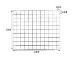
画像データを効率よく符号化・復号化する手法に、JPEG(Joint Photographic Experts Group)方式やMPEG(Movinc Picture Experts Group)方式等があり、一般によく使われている。JPEG方式やMPEG方式では、ブロックを単位にして、様々な処理が行われている。図11は、画像とブロックの関係を示す図であり、A×B画素で構成されている1枚の画像は、8×8画素のブロック単位に分割され、各々のブロック単位で、直交変換や逆直交変換等の処理が行われている。
【0004】
このようなブロック単位の処理は、JPEG方式やMPEG方式のような画像データの符号化処理や復号化処理には適しているものの、画像の拡大や縮小等のリサイズ処理には適していない。
【0005】
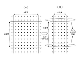
次に、図12の(A)及び図12の(B)を用いて、ブロック単位のリサイズ処理に関して説明する。図12の(A)は、8×8画素で構成されるブロックを示した図であり、図12の(B)は8×8画素で構成されるブロックのうち、ブロック周辺部(点線円)を拡大したものである。 101〜104 はリサイズ処理前の入力画素であり、そのうち画素101 及び102 はブロック(I,J-1)内に、画素103 及び104 はブロック(I,J)内に位置する。105 はリサイズ処理後の出力画素であり、ブロック(I,J)内に位置する。出力画素105 は、入力画素 101〜104 より補間演算によって求められる。このように、ブロック周辺部のリサイズ演算には、複数のブロックの画素情報が必要となる。
【0006】
そこで、一般的には、符号化処理や復号化処理ではブロック単位で処理するものの、リサイズ時には1画面単位でリサイズ処理する手法が多く用いられている。図13は、1画面単位でリサイズ処理することを特徴とする従来の画像処理装置の構成を示すブロック図である。JPEGデコーダ111 は、JPEG符号を復号化し、8×8サイズのブロック単位で画像データを出力する。出力された画像データは、メモリコントローラ113 を経由して、1画面の画像データを格納可能なメモリ114 に格納される。リサイズ回路112 は、メモリコントローラ113 経由でメモリ114 より、画像データを取得する。リサイズ回路112 は、1画面単位でリサイズ処理を行い、リサイズ処理後の画像データは再びメモリコントローラ113経由でメモリ114 に格納される。以上の手法によると、JPEG復号化した画像データを一旦メモリ114 に格納して、1画面の画像に復元した後にリサイズ処理することができる。
【0007】
一方、ブロック単位のリサイズ処理に関しても、従来から提案がなされており、例えば、特開平11−53532号公報に開示がなされている。図14は、ブロック単位でリサイズすることを特徴とする従来の画像処理装置の構成例を示すブロック図である。JPEGデコーダ121 は、JPEG符号を復号化し、8×8サイズのブロック単位で画像データを出力する。JPEGデコーダ121 で復号化された画像データのうち、ブロックの最下ラインの画像データは、1ライン分の容量を有するラインメモリ122 に格納される。また、ブロックの最右列の画像データは、8画素分の容量を有するバッファ123 に格納される。リサイズ回路124 は、隣接ブロックの画像データをラインメモリ122 及びバッファ123 より取得してリサイズ処理を行う。リサイズ回路124 でリサイズ処理された画像データは、メモリコントローラ125 経由でメモリ126 にライトされる。
【0008】
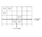
図15は、上記従来例の隣接ブロックデータ取得手法に関する説明図である。現在処理中のブロックが、ブロック(I,J)とすると、上に隣接するブロック(I,J-1)の最下ラインの画素データをラインメモリ122 より取得し、左に隣接するブロック(I-1,J)の最右列の画素データをバッファ123 より取得する。このような従来技術によると、ラインメモリ122 とバッファ123 から、隣接ブロックの画像情報を取得してリサイズ処理するので、ブロック単位でのリサイズ処理が可能となる。
【0009】
【発明が解決しようとする課題】
以上説明した従来例のうち、ブロック単位で復号化された画像データを一旦メモリに格納し、1画面単位でリサイズ処理する手法は、メモリのアクセス効率が悪く、処理時間がかかるという問題を有する。一方、ブロック単位でリサイズ処理する手法によると、メモリのアクセス効率が良く、高速処理が可能である。しかしながら、図14に示すような構成の従来例では、入力データのうちブロック最下ラインのデータを格納するために、ラインメモリの容量が大きいという問題点がある。
【0010】
本発明は、従来の画像データのリサイズ処理における上記問題点を解消するためになされたものであり、従来技術と比較してラインメモリの容量を削減することの可能な、ブロック単位でリサイズ処理する画像処理装置を提供することを目的とする。
【0011】
【課題を解決するための手段】
上記問題点を解決するため、請求項1に係る発明は、N×M(N,Mは2以上の自然数)画素を1ブロックにして複数のブロックで構成される画像データを、ブロック単位に処理する画像処理装置において、前記画像データを第1の方向にリサイズ処理する第1のリサイズ手段と、リサイズ処理対象たるブロックに対して前記第1の方向を横切る第2の方向に隣接する、第1の方向に並ぶブロックに対して該第1のリサイズ手段により処理された画像データの出力の内、前記リサイズ処理対象たるブロックに対して前記第2の方向に隣接する少なくとも1ライン分格納可能なライン記憶手段と、前記第1のリサイズ手段から出力された前記リサイズ処理対象ブロックの画像データと、前記ライン記憶手段から取得した、前記リサイズ処理対象たるブロックに対して前記第2の方向に隣接する少なくとも1ラインの画像データとを用いて、前記第2の方向にリサイズ処理する第2のリサイズ手段とを有するものである。
【0012】
この請求項1に係る発明に関する実施の形態には、第1〜第4の実施の形態が対応する。そして、上記のように構成された画像処理装置においては、ブロック単位の画像データを第1のリサイズ手段で第1の方向にリサイズ処理した後の画像データを、ライン記憶手段に格納し、第2のリサイズ手段は、第1のリサイズ手段からの出力データ及びライン記憶手段に格納されている隣接ブロックの画像データを使用して、第2の方向のリサイズ処理を行う。これにより、画像データをブロック単位にリサイズ処理することができ、且つ第1の方向にリサイズ処理した後の画像データをライン記憶手段に格納するようにしているため、小さい容量のライン記憶手段でリサイズ処理を行うことができる。
【0013】
請求項2に係る発明は、請求項1に係る画像処理装置において、圧縮符号化された画像データをブロック単位で復号化する復号化手段を備え、該復号化手段で復号化された画像データをリサイズ処理することを特徴とするものである。
【0014】
この請求項2に係る発明に関する実施の形態には、第1〜第3の実施の形態が対応する。そして、上記のように構成された画像処理装置においては、本発明に係る画像処理装置は画像データをブロック単位でリサイズ処理するものであるから、圧縮符号化された画像データをブロック単位に復号化する復号化手段を備えている場合、復号化手段でブロック単位に復号化された画像データを、そのままブロック単位でリサイズ処理することができる。
【0015】
請求項3に係る発明は、請求項1に係る画像処理装置において、画像データをブロック単位で圧縮符号化する符号化手段を備え、リサイズ処理した画像データを前記符号化手段で圧縮符号化することを特徴とするものである。
【0016】
この請求項3に係る発明に関する実施の形態には、第4の実施の形態が対応する。そして、上記のように構成された画像処理装置においては、本発明に係る画像処理装置は画像データをブロック単位でリサイズ処理するものであるから、画像データをブロック単位に符号化する符号化手段を備えている場合、ブロック単位でリサイズ処理した画像データを、そのままブロック単位で符号化することができる。
【0017】
請求項4に係る発明は、請求項1に係る画像処理装置において、前記第1のリサイズ手段は、前記画像データを第1の方向の間引きによりリサイズ処理を行うことを特徴とするものである。
【0018】
この請求項4に係る発明に関する実施の形態には、第1の実施の形態が対応する。そして、このように構成された画像処理装置においては、第1のリサイズ手段は、間引きによって第1の方向にリサイズ処理するように構成されているので、簡単な構成で第1の方向のリサイズ処理を実行することができる。
【0019】
請求項5に係る発明は、請求項1に係る画像処理装置において、前記第1のリサイズ手段は、前記画像データを第1の方向の加算平均によりリサイズ処理を行うことを特徴とするものである。
【0020】
この請求項5に係る発明に関する実施の形態には、第1の実施の形態が対応する。そして、このように構成された画像処理装置においては、第1のリサイズ手段は、加算平均によって第1の方向にリサイズ処理するように構成されているので、簡単な構成で第1の方向のリサイズ処理を実行することができる。
【0021】
請求項6に係る発明は、請求項1に係る画像処理装置において、前記N×M画素のブロックのうち、少なくとも第2の方向のブロック画素数の画像データを格納可能な画素記憶手段を備え、前記第1のリサイズ手段は、隣接ブロックの画像データを前記画素記憶手段から取得するように構成されていることを特徴とするものである。
【0022】
この請求項6に係る発明に関する実施の形態には、第2〜第4の実施の形態が対応する。そして、このように構成された画像処理装置においては、第2の方向のブロック画素数の画像データを格納する画素記憶手段を備え、第1のリサイズ手段は隣接ブロックの画像データを画素記憶手段から取得するようになっているので、隣接ブロックの画像データを第1の方向にリサイズ処理に使用でき、より高度なリサイズ処理ができる。
【0023】
請求項7に係る発明は、請求項6に係る画像処理装置において、前記画素記憶手段は、N×M画素のブロックのうち第2の方向のブロック画素数の画像データを格納可能であり、前記第1のリサイズ手段は第1の方向の2点補間によりリサイズ処理を行うことを特徴とするものである。
【0024】
この請求項7に係る発明に関する実施の形態には、第2〜第4の実施の形態が対応する。そして、このように構成された画像処理装置においては、1列分の画素記憶手段を備え、隣接するブロックの1列分のデータを格納することができ、第1のリサイズ手段は2点補間によるリサイズ処理が可能となる。
【0025】
請求項8に係る発明は、請求項6に係る画像処理装置において、前記画素記憶手段は、N×M画素のブロックのうち第2の方向のブロック画素数の3倍の画像データを格納可能であり、前記第1のリサイズ手段は第1の方向の4点補間によりリサイズ処理を行うことを特徴とするものである。
【0026】
この請求項8に係る発明に関する実施の形態には、第2及び第3の実施の形態が対応する。そして、このように構成された画像処理装置においては、3列分の画素記憶手段を備え、隣接ブロックの3列分のデータを格納することができ、第1のリサイズ手段は4点補間によるリサイズ処理が可能となる。
【0027】
請求項9に係る発明は、請求項1に係る画像処理装置において、前記ライン記憶手段は、前記第1のリサイズ手段でリサイズ処理された画像データのうち、第1の方向に1ライン分の画像データを格納可能であり、前記第2のリサイズ手段は、第2の方向の2点補間によるリサイズ処理を行うことを特徴とするものである。
【0028】
この請求項9に係る発明に関する実施の形態には、第1及び第4の実施の形態が対応する。そして、このように構成された画像処理装置においては、1ライン分のライン記憶手段を備え、隣接ブロックの1ライン分のデータを格納することができ、第2のリサイズ手段は2点補間によりリサイズ処理が可能となる。
【0029】
請求項10に係る発明は、請求項1に係る画像処理装置において、前記ライン記憶手段は、前記第1のリサイズ手段でリサイズ処理された画像データのうち、第1の方向に3ライン分の画像データを格納可能であり、前記第2のリサイズ手段は、第2の方向の4点補間によりリサイズ処理を行うことを特徴とするものである。
【0030】
この請求項10に係る発明に関する実施の形態には、第2及び第3の実施の形態が対応する。そして、このように構成された画像処理装置においては、3ライン分のライン記憶手段を備え、隣接ブロックの3ライン分のデータを格納させることができ、第2のリサイズ手段は4点補間によるリサイズ処理が可能となる。
【0031】
請求項11に係る発明は、請求項1に係る画像処理装置において、前記画像処理装置は、第1の方向のリサイズ処理をスルーさせることが可能な第1のリサイズスルー手段を備えていることを特徴とするものである。
【0032】
この請求項11に係る発明に関する実施の形態には、第1の実施の形態が対応する。そして、このように構成された画像処理装置においては、第1の方向のリサイズ処理をスルーさせることの可能な第1のリサイズスルー手段を備えており、第1の方向のリサイズ処理を選択的にスルーさせることができる。
【0033】
請求項12に係る発明は、請求項1又は11に係る画像処理装置において、前記画像処理装置は、第2の方向のリサイズ処理をスルーさせることが可能な第2のリサイズスルー手段を備えていることを特徴とするものである。
【0034】
この請求項12に係る発明に関する実施の形態には、第1の実施の形態が対応する。そして、このように構成された画像処理装置においては、第2の方向のリサイズ処理をスルーさせることの可能な第2のリサイズスルー手段を備えており、第2の方向のリサイズ処理を選択的にスルーさせることができる。
【0035】
請求項13に係る発明は、請求項1に係る画像処理装置において、前記ライン記憶手段は、外部表示装置の表示領域に対応した容量を有することを特徴とするものである。
【0036】
この請求項13に係る発明に関する実施の形態には、第3の実施の形態が対応する。そして、このように構成された画像処理装置においては、ライン記憶手段は、外部表示装置の表示領域に対応した容量を有するようにしているので、どのような拡大率や縮小率であっても、ライン記憶手段を効率よく使用することができる。
【0037】
【発明の実施の形態】
(第1の実施の形態)
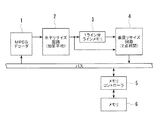
次に、実施の形態について説明する。図1は、本発明に係る画像処理装置の第1の実施の形態の構成を示すブロック図である。図1において、1はMPEG符号データを復号化して、8×8画素サイズのブロック単位で、画像データを出力するMPEGデコーダ、2は該MPEGデコーダ1からブロック単位に出力された画像データを、水平方向にリサイズ処理する水平リサイズ回路、3は該水平リサイズ回路2からの出力データのうち、ブロックの最下ラインの画素データを格納する1ライン分の容量を有するラインメモリ、4は前記水平リサイズ回路2からの出力データ及び前記ラインメモリ3に格納されている画像データを用いて、垂直方向にリサイズ処理する垂直リサイズ回路、5はメモリコントローラ、6はメモリを示している。
【0038】
図2は、本実施の形態における、リサイズ処理態様の一例を示す説明図である。以下の説明では、MPEGデコーダ1からの出力画像サイズを1440×1080画素、最終的に得たい画像サイズを 720×480 画素として説明を行う。
【0039】
次に、図1に基づいて、本実施の形態の動作に関して説明する。MPEGデコーダ1は、MPEG符号データをデコードし、ブロック単位で画像データを出力する。水平リサイズ回路2は、MPEGデコーダ1から出力された画像データを水平方向にリサイズ処理する。このとき、図2に示したように、MPEGデコーダ1からの出力画像サイズを1440×1080画素、最終的に得たい画像サイズを 720×480 とすると、水平リサイズ回路2からの出力画像サイズは、 720×1080画素となる。水平リサイズ手法には、例えば、図3の(A)に示すような隣接する数画素の平均を出力する手法(加算平均)や、図3の(B)に示すような単純に画素を間引く手法(単純間引き・挿入)がある。
【0040】
水平リサイズ回路2でリサイズ処理後の画像データのうち、ブロックの最下ラインのデータは、ラインメモリ3に格納される。このとき、水平方向のリサイズ処理後の画素数は 720画素なので、ラインメモリ3は、 720画素データを格納できる容量を持つものとする。
【0041】
垂直リサイズ回路4は、水平リサイズ回路2で 720×1080画素サイズにリサイズ処理された画像データを、 720×480 画素サイズに垂直リサイズ処理する。垂直リサイズ手法には、例えば、図3の(C)に示すような2点補間による手法がある。ブロックの周辺部のように、隣接するブロックの画素情報が必要な場合は、ラインメモリ3に格納されているデータを利用して垂直リサイズ処理を行う。なお、リサイズ方式には、他に図3の(D)に示す4点補間による処理方式があるが、これについては、後述する。垂直リサイズ回路4でリサイズ処理された画像データは、メモリコントローラ5経由でメモリ6に格納される。
【0042】
以上の処理により、MPEGデコーダ1からの1440×1080サイズの画像データを、ブロック単位にリサイズ処理して、 720×480 サイズの画像データを得ることができる。先に示した従来例によると、入力データをラインメモリに格納していたため、ラインメモリの容量は1440画素分必要であったが、本実施の形態によると、水平リサイズ処理後にラインメモリに格納するため、ラインメモリ容量は 720画素分でよい。
【0043】
図4の(A),(B)は、本実施の形態における水平リサイズ処理前後のブロックサイズを示す図であり、図4の(A)はMPEGデコーダ1が出力するブロックサイズを、図4の(B)は水平リサイズ回路2が出力するブロックサイズを示す。図4の(A)に示すように、MPEGデコーダ1では8×8画素をブロックとして取り扱うが、水平リサイズ回路2でリサイズ処理することにより、図4の(B)に示すように、ブロックサイズは4×8画素に変更され、そのうち最下ラインのデータがラインメモリ3に格納されることを示している。なお、水平リサイズ処理後のブロックサイズは8×8のままで、水平方向のブロック数を半分にしてもよい。
【0044】
図5は、本実施の形態の変形例を示すブロック図である。図5において、水平リサイズ回路2は水平リサイズ処理を行う演算器7の他に選択回路8を備え、垂直リサイズ回路4は垂直リサイズ処理を行う演算器9の他に選択回路10を備えている。その他の構成は、図1と同様である。このように構成された変形例では、水平リサイズ回路2及び垂直リサイズ回路4では、選択回路8,10によって、どちらか一方又は両方のリサイズ機能をスルーさせることができる。
【0045】
本実施の形態によると、画像データをブロック単位でリサイズ処理することができ、水平方向にリサイズ処理した後の画像データをラインメモリに格納するため、従来例と比較して小さいラインメモリ容量でリサイズ処理を実現することができる。また、リサイズ回路を水平方向と垂直方向で分割しているため、水平方向と垂直方向とで、縮小率あるいは拡大率や、リサイズ手法が異なる場合への対応が容易となる。
【0046】
(第2の実施の形態)
図6は、本発明の第2の実施の形態に係る画像処理装置の構成を示すブロック図である。図6において、11はJPEG符号データを復号化して8×8画素サイズのブロック単位に画像データを出力するJPEGデコーダ、12〜14は該JPEGデコーダ11からブロック単位に出力された画像データを格納する8画素分の容量を持つバッファ、15は前記JPEGデコーダ11からの出力データ及び前記バッファ12〜14に格納されているデータを用いて、水平方向にリサイズ処理する水平リサイズ回路、16〜18は該水平リサイズ回路15の出力データをライン単位で格納する1ライン分の容量を持つラインメモリ、19は前記水平リサイズ回路15の出力データ及び前記ラインメモリ16〜18に格納されているデータを用いて、垂直方向にリサイズ処理する垂直リサイズ回路、20はメモリコントローラ、21はメモリを示している。
【0047】
次に、このように構成されている第2の実施の形態における水平リサイズ手法に関して説明する。第1の実施の形態では、水平リサイズ方式は、図3の(A)に示す加算平均方式、又は図3の(B)に示す単純間引き挿入方式であり、水平隣接ブロックの画素情報を取得するためのバッファは不要である。本実施の形態では、水平リサイズ方式は、図3の(D)に示す4点補間方式を用いており、水平隣接ブロックの画素情報を取得するためのバッファ12〜14を備えている。
【0048】
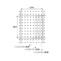
図7は、本実施の形態におけるバッファ12〜14への格納方法を示す説明図である。JPEGデコーダ11からブロック単位に出力された画像データのうち、8×8画素のブロック内で最右列の8画素がバッファ12に、右から2番目の列の8画素がバッファ13に、右から3番目の列の8画素がバッファ14に、それぞれ格納される。4点補間方式の水平リサイズ処理には4画素分の情報が必要であるが、ブロック周辺部では、最大3画素分の情報を隣接ブロックから取得する必要がある。水平リサイズ回路15は、必要に応じてバッファ12〜14より画素情報を取得し、水平リサイズ処理を行う。なお、水平リサイズ回路15でのリサイズ方式に、図3の(C)に示すような2点補間方式を適用する場合は、図6に示した本実施の形態においてバッファ13及びバッファ14を取り除いた構成としてもよい。
【0049】
次に、垂直リサイズ手法に関して説明する。第1の実施の形態では、垂直リサイズ方式は、図3の(C)に示す2点補間方式を用いており、ラインメモリは1つである。本実施の形態では、垂直リサイズ方式は図3の(D)に示す4点補間方式を用いており、ラインメモリはラインメモリ16〜ラインメモリ18の合計3つとなっている。水平リサイズ回路15の出力データのうち、ブロックの最下ラインの画素データはラインメモリ16に、下から2番目のラインの画素データはラインメモリ17に、下から3番目のラインの画素データはラインメモリ18にそれぞれ格納される。垂直リサイズ回路19は、必要に応じてラインメモリ16〜18より画素情報を取得することにより、4点補間方式による垂直リサイズ処理が可能となる。
【0050】
本実施の形態によると、第1の実施の形態と比較して、隣接ブロックの情報を取得するためのバッファ及びラインメモリを増設した構成となっている。このため、第1の実施の形態と比較して高度な水平リサイズ方式及び垂直リサイズ方式を適用することができ、高画質な出力画像を得ることができる。また、本発明によると、従来例と比較してラインメモリの容量を節約することができるので、本実施の形態のようにラインメモリの本数を増設した場合でも、従来例に比べて回路規模の増加を抑えることができる。
【0051】
(第3の実施の形態)
図8は、本発明の第3の実施の形態に係る画像処理装置の構成を示すブロック図である。この実施の形態は、ビデオエンコーダ22を設けた以外の構成は、第2の実施の形態と同様であるので、その説明を省略する。ビデオエンコーダ22は、メモリ21に格納されているリサイズ処理後の画像データを、メモリコントローラ20経由で取得し、外部画像表示装置にデータを出力するものである。なお、本実施の形態におけるラインメモリ16〜18は、外部画像表示装置の有効領域に対応した容量を有することを特徴としている。例えば、外部画像表示装置の有効領域の大きさを 720×480 とすると、ラインメモリ16〜18はそれぞれ 720画素分の容量を持つものとする。
【0052】
次に、2048×1536画素サイズの画像を 720×480 画素に縮小する場合と、 320×240 画素サイズの画像を 720×480 画素に拡大する場合について説明する。JPEGデコーダ11で復号化された画素サイズが2048×1536の場合、水平リサイズ回路15は縮小処理を施して、 720×1536サイズの画像データを出力する。ラインメモリ16〜18には、それぞれ 720画素の画像データが格納され、垂直リサイズ回路19で 720×480 サイズの画像データが得られる。
【0053】
一方、JPEGデコーダ11で復号化された画素サイズが 320×240 の場合、水平リサイズ回路15は拡大処理を施して、 720×240 サイズの画像データを出力する。ラインメモリ16〜18には、それぞれ 720画素の画像データが格納され、垂直リサイズ回路19で 720×480 サイズの画像データが得られる。
【0054】
以上のように、外部画像表示装置の有効領域が 720×480 の場合、水平リサイズ処理後の画像の横幅は 720画素となるので、ラインメモリ16〜18は 720画素を格納できる容量を持てばよいことがわかる。
【0055】
本実施の形態によると、外部表示装置の表示領域に対応してラインメモリの容量を決定するので、どのような拡大率あるいは縮小率のリサイズ処理であっても、ラインメモリを効率よく活用することができる。
【0056】
(第4の実施の形態)
図9は、本発明の第4の実施の形態に係る画像処理装置の構成を示すブロック図である。図9において、31はブロック単位で入力される画像データのうち、ブロックの垂直方向画素分の容量を有するバッファ、32は前記ブロック単位で入力される画像データを、水平方向にリサイズ処理する水平リサイズ回路、33は該水平リサイズ回路32の出力データのうち、最下ラインのデータを格納する1ライン分の容量を有するラインメモリ、34は前記水平リサイズ回路32の出力データを垂直方向にリサイズ処理する垂直リサイズ回路、35は垂直リサイズ回路34の出力データをJPEG符号化するJPEGエンコーダ、36はメモリコントローラ、37はメモリを示している。
【0057】
本実施の形態においては、 720×480 画素の入力画像を 352×288 画素に縮小し、その後JPEG符号化する例に関して説明する。なお、JPEG符号化は8×8画素のブロック単位で行うものとする。
【0058】
次に、本実施の形態における動作に関して説明する。メモリ37に格納されている画像データは、メモリコントローラ36を介して、バッファ31及び水平リサイズ回路32に入力される。このとき、メモリ37からの画像のリードはN×M画素のブロック単位で行われるが、水平方向の画素数N及び垂直方向の画素数Mは画像の拡大率あるいは縮小率より決定され、この場合、例えばNは16又は17,Mは13又は14とする。
【0059】
バッファ31には、メモリ37からブロック単位でリードされたデータのうち、N×M画素の最右列の画素が格納される。本実施の形態の入力ブロックサイズは最大17×14画素なので、バッファ31は14画素分の容量を持つ。水平リサイズ回路32は、N×M画素のブロックを水平方向にリサイズ処理して、8×M画素のブロックを生成する。このとき、隣接ブロックの情報はバッファ31より取得し、2点補間演算によって水平リサイズ処理を実現する。
【0060】
水平リサイズ回路32で出力されたデータのうち、ブロックの最下ラインの画素情報はラインメモリ33に格納される。ラインメモリ33は 352画素分の容量を有する。垂直リサイズ回路34は、水平リサイズ回路32の出力データ及びラインメモリ33に格納されているデータを用いて、2点補間演算により、垂直リサイズ処理を実施する。垂直リサイズ回路34に入力されるブロックサイズは8×M画素であり、出力ブロックサイズは8×8画素となる。垂直リサイズ回路34から出力された画像データは、JPEGエンコーダ35にてJPEG符号化処理が施され、メモリコントローラ36経由でメモリ37に格納される。
【0061】
第1〜第3の実施の形態では、復号化後にリサイズ処理する手法について説明したが、本実施の形態によると、ブロック単位でリサイズ処理した後に符号化することも可能である。また、第1及び第2の実施の形態と同様に、第1の方向にリサイズ処理した後の画像データをラインメモリに格納するようにしているため、従来例と比較して小さいラインメモリ容量で、リサイズ処理を実現することができる。
【0062】
図10は、ブロック単位でのデータ出力値の例を示す図である。以上説明した第1〜第4の実施の形態におけるデータ出力順は、例えば、図10の(A),図10の(B)及び図10の(C)のどのデータ出力順にも対応可能である。また、ブロックサイズに関しても、当然8×8画素サイズに限定されるものではなく、例えば図10の(D)に示すように、8×8画素サイズのブロックを複数個(図示例では4個)集めた16×16サイズのマクロブロックを単位として、処理を行うことも可能である。
【0063】
また、上記第1〜第4の実施の形態における説明においては、JPEG及びMPEGに適用した例に関して説明したが、それぞれの実施の形態における画像圧縮伸長方法は、特に限定されるものではなく、JPEGやMPEGやH261やその他の画像圧縮伸長方法であってもよい。
【0064】
【発明の効果】
以上実施の形態に基づいて説明したように、請求項1に係る発明によれば、画像データをブロック単位でリサイズ処理することができ、且つ第1の方向にリサイズ処理した後の画像データをライン記憶手段に格納するようにしているため、小さい容量のライン記憶手段でリサイズ処理を行うことができる。また請求項2に係る発明によれば、画像データをブロック単位でリサイズ処理するものなので、復号化手段でブロック単位に復号化された画像データを、そのままブロック単位でリサイズ処理することができる。また請求項3に係る発明によれば、画像データがブロック単位で処理されているので、ブロック単位でリサイズ処理された画像データを、そのままブロック単位で符号化することができる。また請求項4及び5に係る発明によれば、第1のリサイズ手段は、間引き又は加算平均によって第1の方向にリサイズ処理するようにしているので、簡単な構成で、第1の方向のリサイズ処理を実行することができる。また請求項6に係る発明によれば、隣接ブロックの画像データを第1の方向のリサイズ処理に使用でき、より高度なリサイズ処理ができる。
【0065】
また請求項7に係る発明によれば、1列分の画素記憶手段を備え、隣接するブロックの1列分のデータを格納できるので、第1のリサイズ手段は2点補間によるリサイズ処理が可能となる。また請求項8に係る発明によれば、3列分の画素記憶手段を備え、隣接するブロックの3列分のデータを格納できるので、第1のリサイズ手段は4点補間によるリサイズ処理が可能となる。また請求項9に係る発明によれば、1ライン分のライン記憶手段を備え、隣接ブロックの1ライン分のデータを格納できるので、第2のリサイズ手段は2点補間が可能となる。また請求項10に係る発明によれば、3ライン分のライン記憶手段を備え、隣接ブロックの3ライン分のデータを格納できるので、第2のリサイズ手段は4点補間が可能となる。また請求項11に係る発明によれば、第1のリサイズスルー手段を備えているので、第1の方向のリサイズ処理を選択的にスルーさせることができる。また請求項12に係る発明によれば、第2のリサイズスルー手段を備えているので、第2の方向のリサイズ処理を選択的にスルーさせることができる。また請求項13に係る発明によれば、ライン記憶手段は、外部表示装置の表示領域に対応した容量を有するように構成しているので、どのような拡大率や縮小率であっても、ライン記憶手段を効率よく使用することができる。
【図面の簡単な説明】
【図1】本発明に係る画像処理装置の第1の実施の形態を示すブロック図である。
【図2】リサイズ処理態様の一例を示す図である。
【図3】リサイズ処理手法を示す説明図である。
【図4】図1に示した第1の実施の形態における水平リサイズ処理前後のブロックサイズを示す図である。
【図5】図1に示した第1の実施の形態の変形例を示すブロック図である。
【図6】本発明の第2の実施の形態に係る画像処理装置を示すブロック図である。
【図7】図6に示した第2の実施の形態におけるバッファへの格納態様を示す説明図である。
【図8】本発明の第3の実施の形態に係る画像処理装置を示すブロック図である。
【図9】本発明の第4の実施の形態に係る画像処理装置を示すブロック図である。
【図10】本発明の各実施の形態におけるブロック単位でのデータ出力順、及びブロックサイズの他の例を示す図である。
【図11】画像とブロック単位との関係を示す図である。
【図12】8×8画素で構成されるブロック及びブロック周辺部を拡大して示す図である。
【図13】従来の1画面単位でリサイズ処理を行う画像処理装置の構成例を示すブロック図である。
【図14】従来のブロック単位でリサイズ処理を行う画像処理装置の構成例を示すブロック図である。
【図15】図14に示した従来例における隣接ブロックデータを取得する手法を示す説明図である。
【符号の説明】
1 MPEGデコーダ
2 水平リサイズ回路
3 ラインメモリ
4 垂直リサイズ回路
5 メモリコントローラ
6 メモリ
7 演算器
8 選択回路
9 演算器
10 選択回路
11 JPEGデコーダ
12,13,14 バッファ
15 水平リサイズ回路
16,17,18 ラインメモリ
19 垂直リサイズ回路
20 メモリコントローラ
21 メモリ
22 ビデオエンコーダ
31 バッファ
32 水平リサイズ回路
33 ラインメモリ
34 垂直リサイズ回路
35 JPEGデコーダ
36 メモリコントローラ
37 メモリ[0001]
BACKGROUND OF THE INVENTION
The present invention relates to an image processing apparatus that resizes image data composed of a plurality of blocks by setting N × M (N and M are natural numbers of 2 or more) pixels as one block, and particularly for encoding and coding. The present invention relates to an image processing apparatus that performs resizing processing before and after decoding.
[0002]
[Prior art]
[Patent Document 1]
JP-A-11-53532
[0003]
As methods for efficiently encoding / decoding image data, there are a JPEG (Joint Photographic Experts Group) method, an MPEG (Movinc Picture Experts Group) method, and the like, which are commonly used. In the JPEG system and the MPEG system, various processes are performed in units of blocks. FIG. 11 is a diagram showing the relationship between an image and a block. One image composed of A × B pixels is divided into 8 × 8 pixel blocks, and orthogonal transform or Processing such as inverse orthogonal transformation is performed.
[0004]
Such block unit processing is suitable for image data encoding processing and decoding processing such as JPEG and MPEG, but is not suitable for resizing processing such as image enlargement or reduction.
[0005]
Next, the resizing process in units of blocks will be described with reference to FIGS. 12A and 12B. FIG. 12A is a diagram showing a block composed of 8 × 8 pixels, and FIG. 12B is a block peripheral portion (dotted circle) among blocks composed of 8 × 8 pixels. Is an enlarged version.
[0006]
Thus, generally, although encoding processing and decoding processing are performed in units of blocks, a method of performing resizing processing in units of one screen at the time of resizing is often used. FIG. 13 is a block diagram showing a configuration of a conventional image processing apparatus characterized in that resizing processing is performed in units of one screen. The
[0007]
On the other hand, resize processing in units of blocks has been proposed in the past, and is disclosed in, for example, Japanese Patent Application Laid-Open No. 11-53532. FIG. 14 is a block diagram showing a configuration example of a conventional image processing apparatus characterized by resizing in units of blocks. The
[0008]
FIG. 15 is an explanatory diagram regarding the adjacent block data acquisition method of the conventional example. If the block currently being processed is a block (I, J), the pixel data of the lowermost line of the upper adjacent block (I, J-1) is obtained from the
[0009]
[Problems to be solved by the invention]
Among the conventional examples described above, the method of temporarily storing the image data decoded in units of blocks and resizing the data in units of one screen has a problem that the access efficiency of the memory is poor and the processing time is long. On the other hand, according to the resizing process in units of blocks, the memory access efficiency is good and high-speed processing is possible. However, the conventional example configured as shown in FIG. 14 has a problem that the capacity of the line memory is large in order to store the data of the bottom line of the block among the input data.
[0010]
The present invention has been made to solve the above-described problems in the conventional image data resizing processing, and performs resizing processing in units of blocks that can reduce the capacity of the line memory as compared with the prior art. An object is to provide an image processing apparatus.
[0011]
[Means for Solving the Problems]
In order to solve the above-described problems, the invention according to claim 1 processes image data composed of a plurality of blocks by setting N × M (N and M are natural numbers of 2 or more) pixels as one block. In the image processing apparatus, a first resizing unit for resizing the image data in a first direction and a block to be resized In a second direction across the first direction Output of image data processed by the first resizing means for adjacent blocks arranged in the first direction And adjacent to the block to be resized in the second direction. Line storage means capable of storing at least one line, image data of the resizing process target block output from the first resizing means, and acquired from the line storage means , At least one line adjacent to the block to be resized in the second direction Using the image data of Said And second resizing means for resizing in the second direction.
[0012]
The first to fourth embodiments correspond to the embodiment relating to the first aspect of the present invention. In the image processing apparatus configured as described above, the image data obtained by resizing the block-unit image data in the first direction by the first resizing means is stored in the line storage means, The resizing means performs resizing processing in the second direction using the output data from the first resizing means and the image data of the adjacent blocks stored in the line storage means. As a result, the image data can be resized in units of blocks, and the image data after being resized in the first direction is stored in the line storage means. Processing can be performed.
[0013]
According to a second aspect of the present invention, in the image processing apparatus according to the first aspect, the image processing apparatus further comprises decoding means for decoding the compression-encoded image data in units of blocks, and the image data decoded by the decoding means It is characterized by resizing processing.
[0014]
The first to third embodiments correspond to the embodiment relating to the second aspect of the invention. In the image processing apparatus configured as described above, the image processing apparatus according to the present invention resizes image data in units of blocks, so that compression-coded image data is decoded in units of blocks. In the case where the decoding means is provided, the image data decoded in the block unit by the decoding means can be resized in the block unit as it is.
[0015]
According to a third aspect of the present invention, in the image processing apparatus according to the first aspect, the image processing apparatus further comprises an encoding unit that compresses and encodes image data in units of blocks, and the resized image data is compressed and encoded by the encoding unit. It is characterized by.
[0016]
The fourth embodiment corresponds to the embodiment relating to the third aspect of the invention. In the image processing apparatus configured as described above, since the image processing apparatus according to the present invention resizes image data in units of blocks, encoding means for encoding image data in units of blocks is provided. When the image data is provided, the image data that has been resized on a block basis can be encoded on a block basis.
[0017]
According to a fourth aspect of the present invention, in the image processing apparatus according to the first aspect, the first resizing unit performs a resizing process on the image data by thinning out in a first direction.
[0018]
The first embodiment corresponds to an embodiment related to the invention according to claim 4. In the image processing apparatus configured as described above, the first resizing unit is configured to perform the resizing process in the first direction by thinning out. Therefore, the resizing process in the first direction with a simple configuration. Can be executed.
[0019]
According to a fifth aspect of the present invention, in the image processing apparatus according to the first aspect, the first resizing unit performs a resizing process on the image data by addition averaging in a first direction. .
[0020]
The first embodiment corresponds to an embodiment related to the invention according to
[0021]
The invention according to
[0022]
The second to fourth embodiments correspond to the embodiment relating to the sixth aspect of the invention. The image processing apparatus configured as described above includes pixel storage means for storing image data of the number of block pixels in the second direction, and the first resizing means receives image data of adjacent blocks from the pixel storage means. Since the image data is acquired, the image data of the adjacent block can be used in the resizing process in the first direction, and a more advanced resizing process can be performed.
[0023]
According to a seventh aspect of the present invention, in the image processing apparatus according to the sixth aspect, the pixel storage means can store image data of the number of block pixels in the second direction among the N × M pixel blocks, and The first resizing means is characterized in that resizing processing is performed by two-point interpolation in the first direction.
[0024]
The second to fourth embodiments correspond to the embodiment relating to the seventh aspect of the invention. The image processing apparatus configured as described above includes a pixel storage unit for one column, can store data for one column of adjacent blocks, and the first resizing unit is based on two-point interpolation. Resizing processing is possible.
[0025]
According to an eighth aspect of the present invention, in the image processing apparatus according to the sixth aspect, the pixel storage means is capable of storing image data that is three times the number of block pixels in the second direction among the N × M pixel blocks. The first resizing means performs resizing processing by four-point interpolation in the first direction.
[0026]
The second and third embodiments correspond to the embodiment relating to the eighth aspect of the invention. The image processing apparatus configured as described above includes pixel storage means for three columns, can store data for three columns of adjacent blocks, and the first resizing means performs resizing by four-point interpolation. Processing is possible.
[0027]
According to a ninth aspect of the present invention, in the image processing apparatus according to the first aspect, the line storage means includes an image for one line in the first direction among the image data resized by the first resize means. Data can be stored, and the second resizing means performs resizing processing by two-point interpolation in the second direction.
[0028]
The first and fourth embodiments correspond to the embodiment related to the ninth aspect of the invention. The image processing apparatus configured as described above includes a line storage unit for one line, can store data for one line of an adjacent block, and the second resize unit performs resizing by two-point interpolation. Processing is possible.
[0029]
According to a tenth aspect of the present invention, in the image processing apparatus according to the first aspect, the line storage means includes an image for three lines in the first direction among the image data resized by the first resize means. Data can be stored, and the second resizing means performs resizing processing by four-point interpolation in the second direction.
[0030]
The second and third embodiments correspond to the embodiment related to the invention according to
[0031]
According to an eleventh aspect of the present invention, in the image processing apparatus according to the first aspect, the image processing apparatus includes a first resize through means capable of passing through the resize process in the first direction. It is a feature.
[0032]
The first embodiment corresponds to the embodiment relating to the invention of
[0033]
According to a twelfth aspect of the present invention, in the image processing apparatus according to the first or eleventh aspect, the image processing apparatus includes a second resize through means capable of allowing a resize process in the second direction to pass through. It is characterized by this.
[0034]
The first embodiment corresponds to the embodiment related to the invention of
[0035]
The invention according to
[0036]
The third embodiment corresponds to the embodiment relating to the invention of
[0037]
DETAILED DESCRIPTION OF THE INVENTION
(First embodiment)
Next, embodiments will be described. FIG. 1 is a block diagram showing a configuration of a first embodiment of an image processing apparatus according to the present invention. In FIG. 1, 1 is an MPEG decoder that decodes MPEG code data and outputs image data in units of 8 × 8 pixel blocks, and 2 is an image data output from the
[0038]
FIG. 2 is an explanatory diagram illustrating an example of a resizing process according to the present embodiment. In the following description, it is assumed that the output image size from the
[0039]
Next, the operation of the present embodiment will be described with reference to FIG. The
[0040]
Of the image data after the resizing process by the
[0041]
The vertical resizing circuit 4 performs vertical resizing processing on the image data resized to 720 × 1080 pixel size by the
[0042]
By the above processing, the image data of 1440 × 1080 size from the
[0043]
4A and 4B are diagrams showing the block sizes before and after the horizontal resizing process in this embodiment, and FIG. 4A shows the block sizes output by the
[0044]
FIG. 5 is a block diagram showing a modification of the present embodiment. In FIG. 5, the
[0045]
According to the present embodiment, the image data can be resized in units of blocks, and the image data after the resize process in the horizontal direction is stored in the line memory. Therefore, the resize is performed with a smaller line memory capacity compared to the conventional example. Processing can be realized. Further, since the resizing circuit is divided in the horizontal direction and the vertical direction, it is easy to cope with a case where the reduction ratio or the enlargement ratio and the resizing method are different between the horizontal direction and the vertical direction.
[0046]
(Second Embodiment)
FIG. 6 is a block diagram showing a configuration of an image processing apparatus according to the second embodiment of the present invention. In FIG. 6, 11 is a JPEG decoder that decodes JPEG code data and outputs image data in units of 8 × 8 pixel size, and 12 to 14 store image data output from the
[0047]
Next, a horizontal resizing method in the second embodiment configured as described above will be described. In the first embodiment, the horizontal resizing method is an addition averaging method shown in FIG. 3A or a simple thinning insertion method shown in FIG. 3B, and acquires pixel information of horizontal adjacent blocks. No buffer is needed. In the present embodiment, the horizontal resizing method uses a four-point interpolation method shown in FIG. 3D, and includes
[0048]
FIG. 7 is an explanatory diagram showing a storage method in the
[0049]
Next, the vertical resizing method will be described. In the first embodiment, the vertical resizing method uses the two-point interpolation method shown in FIG. 3C, and there is one line memory. In the present embodiment, the vertical resizing method uses the four-point interpolation method shown in FIG. 3D, and the line memory has a total of three
[0050]
According to the present embodiment, compared to the first embodiment, a buffer and a line memory for acquiring information on adjacent blocks are added. For this reason, an advanced horizontal resizing method and vertical resizing method can be applied as compared with the first embodiment, and an output image with high image quality can be obtained. In addition, according to the present invention, the capacity of the line memory can be saved as compared with the conventional example. Therefore, even when the number of line memories is increased as in this embodiment, the circuit scale is larger than that of the conventional example. The increase can be suppressed.
[0051]
(Third embodiment)
FIG. 8 is a block diagram showing a configuration of an image processing apparatus according to the third embodiment of the present invention. In this embodiment, the configuration other than the provision of the
[0052]
Next, a case where an image having a size of 2048 × 1536 pixels is reduced to 720 × 480 pixels and a case where an image having a size of 320 × 240 pixels is enlarged to 720 × 480 pixels will be described. When the pixel size decoded by the
[0053]
On the other hand, when the pixel size decoded by the
[0054]
As described above, when the effective area of the external image display device is 720 × 480, the horizontal width of the image after the horizontal resizing process is 720 pixels, so the
[0055]
According to the present embodiment, since the capacity of the line memory is determined in accordance with the display area of the external display device, the line memory can be efficiently used regardless of the enlargement ratio or the reduction ratio. Can do.
[0056]
(Fourth embodiment)
FIG. 9 is a block diagram showing a configuration of an image processing apparatus according to the fourth embodiment of the present invention. In FIG. 9, 31 is a buffer having a capacity corresponding to a pixel in the vertical direction of a block among image data input in units of blocks, and 32 is a horizontal resize for resizing the image data input in units of blocks in the horizontal direction. A
[0057]
In the present embodiment, an example in which an input image of 720 × 480 pixels is reduced to 352 × 288 pixels and then JPEG encoded will be described. Note that JPEG encoding is performed in units of 8 × 8 pixel blocks.
[0058]
Next, the operation in this embodiment will be described. The image data stored in the
[0059]
The
[0060]
Of the data output from the
[0061]
In the first to third embodiments, the method of performing the resizing process after decoding has been described. However, according to the present embodiment, it is also possible to perform encoding after performing the resizing process in units of blocks. Similarly to the first and second embodiments, the image data after the resizing process in the first direction is stored in the line memory, so that the line memory capacity is small compared to the conventional example. Resize processing can be realized.
[0062]
FIG. 10 is a diagram illustrating an example of a data output value in units of blocks. The data output order in the first to fourth embodiments described above can correspond to, for example, any data output order shown in FIGS. 10A, 10B, and 10C. . Further, the block size is not limited to the 8 × 8 pixel size, and a plurality of blocks of 8 × 8 pixel size (four in the illustrated example) are provided as shown in FIG. It is also possible to perform processing in units of collected 16 × 16 macroblocks.
[0063]
In the description of the first to fourth embodiments, examples applied to JPEG and MPEG have been described. However, the image compression / decompression method in each embodiment is not particularly limited. MPEG, H261, and other image compression / decompression methods may be used.
[0064]
【The invention's effect】
As described above based on the embodiments, according to the first aspect of the invention, the image data can be resized in units of blocks, and the image data after the resizing process in the first direction is line-processed. Since the data is stored in the storage unit, the resizing process can be performed with a line storage unit having a small capacity. According to the second aspect of the present invention, since the image data is resized in units of blocks, the image data decoded in units of blocks by the decoding unit can be resized in units of blocks. According to the invention of
[0065]
According to the seventh aspect of the invention, since the pixel storage means for one column is provided and data for one column of adjacent blocks can be stored, the first resizing means can perform resizing processing by two-point interpolation. Become. According to the eighth aspect of the present invention, since the pixel storage means for three columns is provided and data for three columns of adjacent blocks can be stored, the first resizing means can perform resizing processing by four-point interpolation. Become. According to the ninth aspect of the invention, since the line storage means for one line is provided and the data for one line of the adjacent block can be stored, the second resizing means can perform two-point interpolation. According to the invention of
[Brief description of the drawings]
FIG. 1 is a block diagram showing a first embodiment of an image processing apparatus according to the present invention.
FIG. 2 is a diagram illustrating an example of a resizing processing mode.
FIG. 3 is an explanatory diagram showing a resizing processing method.
4 is a diagram showing block sizes before and after horizontal resize processing in the first embodiment shown in FIG. 1; FIG.
FIG. 5 is a block diagram showing a modification of the first embodiment shown in FIG.
FIG. 6 is a block diagram showing an image processing apparatus according to a second embodiment of the present invention.
FIG. 7 is an explanatory diagram showing a storage mode in a buffer in the second embodiment shown in FIG. 6;
FIG. 8 is a block diagram showing an image processing apparatus according to a third embodiment of the present invention.
FIG. 9 is a block diagram showing an image processing apparatus according to a fourth embodiment of the present invention.
FIG. 10 is a diagram showing another example of the data output order and block size in units of blocks in each embodiment of the present invention.
FIG. 11 is a diagram illustrating a relationship between an image and a block unit.
FIG. 12 is an enlarged view showing a block composed of 8 × 8 pixels and a block peripheral portion.
FIG. 13 is a block diagram illustrating a configuration example of a conventional image processing apparatus that performs resizing processing in units of one screen.
FIG. 14 is a block diagram illustrating a configuration example of an image processing apparatus that performs resizing processing in units of conventional blocks.
15 is an explanatory diagram showing a technique for acquiring adjacent block data in the conventional example shown in FIG. 14;
[Explanation of symbols]
1 MPEG decoder
2 Horizontal resizing circuit
3 line memory
4 Vertical resizing circuit
5 Memory controller
6 memory
7 Calculator
8 Selection circuit
9 Calculator
10 Selection circuit
11 JPEG decoder
12, 13, 14 buffers
15 Horizontal resizing circuit
16, 17, 18 line memory
19 Vertical resizing circuit
20 Memory controller
21 memory
22 Video encoder
31 buffers
32 Horizontal resizing circuit
33 line memory
34 Vertical resizing circuit
35 JPEG decoder
36 Memory controller
37 memory
Claims (13)
前記画像データを第1の方向にリサイズ処理する第1のリサイズ手段と、
リサイズ処理対象たるブロックに対して前記第1の方向を横切る第2の方向に隣接する、第1の方向に並ぶブロックに対して該第1のリサイズ手段により処理された画像データの出力の内、前記リサイズ処理対象たるブロックに対して前記第2の方向に隣接する少なくとも1ライン分格納可能なライン記憶手段と、
前記第1のリサイズ手段から出力された前記リサイズ処理対象ブロックの画像データと、前記ライン記憶手段から取得した、前記リサイズ処理対象たるブロックに対して前記第2の方向に隣接する少なくとも1ラインの画像データとを用いて、前記第2の方向にリサイズ処理する第2のリサイズ手段とを有する画像処理装置。In an image processing apparatus that processes image data composed of a plurality of blocks with N × M (N and M are natural numbers of 2 or more) pixels as one block,
First resizing means for resizing the image data in a first direction;
For the resizing target serving blocks adjacent in a second direction crossing the first direction, of the output of the image data processed by the first resizing it means relative blocks arranged in a first direction, Line storage means capable of storing at least one line adjacent to the block to be resized in the second direction ;
The image data of the block to be resized output from the first resizing unit and the image of at least one line adjacent to the block to be resized acquired from the line storage unit in the second direction. by using the data, the image processing apparatus and a second resizing means for resizing process in the second direction.
Priority Applications (2)
| Application Number | Priority Date | Filing Date | Title |
|---|---|---|---|
| JP2003117784A JP4109151B2 (en) | 2003-04-23 | 2003-04-23 | Image processing device |
| US10/826,342 US20040213467A1 (en) | 2003-04-23 | 2004-04-19 | Image processing apparatus |
Applications Claiming Priority (1)
| Application Number | Priority Date | Filing Date | Title |
|---|---|---|---|
| JP2003117784A JP4109151B2 (en) | 2003-04-23 | 2003-04-23 | Image processing device |
Publications (2)
| Publication Number | Publication Date |
|---|---|
| JP2004328178A JP2004328178A (en) | 2004-11-18 |
| JP4109151B2 true JP4109151B2 (en) | 2008-07-02 |
Family
ID=33296345
Family Applications (1)
| Application Number | Title | Priority Date | Filing Date |
|---|---|---|---|
| JP2003117784A Expired - Fee Related JP4109151B2 (en) | 2003-04-23 | 2003-04-23 | Image processing device |
Country Status (2)
| Country | Link |
|---|---|
| US (1) | US20040213467A1 (en) |
| JP (1) | JP4109151B2 (en) |
Families Citing this family (5)
| Publication number | Priority date | Publication date | Assignee | Title |
|---|---|---|---|---|
| JP4380740B2 (en) | 2007-07-09 | 2009-12-09 | セイコーエプソン株式会社 | Image processing device |
| JP4380741B2 (en) | 2007-07-09 | 2009-12-09 | セイコーエプソン株式会社 | Image processing device |
| US8111331B2 (en) * | 2007-07-09 | 2012-02-07 | Cisco Technology, Inc. | Image resizer and resizing method |
| JP5639436B2 (en) * | 2010-10-18 | 2014-12-10 | 株式会社メガチップス | Image processing apparatus and method of operating image processing apparatus |
| US20230245265A1 (en) * | 2022-01-31 | 2023-08-03 | Texas Instruments Incorporated | Methods and apparatus to warp images for video processing |
Family Cites Families (11)
| Publication number | Priority date | Publication date | Assignee | Title |
|---|---|---|---|---|
| EP0644684B1 (en) * | 1993-09-17 | 2000-02-02 | Eastman Kodak Company | Digital resampling integrated circuit for fast image resizing applications |
| US5574572A (en) * | 1994-09-07 | 1996-11-12 | Harris Corporation | Video scaling method and device |
| US5963262A (en) * | 1997-06-30 | 1999-10-05 | Cirrus Logic, Inc. | System and method for scaling images and reducing flicker in interlaced television images converted from non-interlaced computer graphics data |
| US6724948B1 (en) * | 1999-12-27 | 2004-04-20 | Intel Corporation | Scaling images for display |
| JP4112187B2 (en) * | 2001-03-01 | 2008-07-02 | 富士フイルム株式会社 | Image processing method, apparatus, and program |
| JP4065503B2 (en) * | 2001-08-21 | 2008-03-26 | キヤノン株式会社 | Image processing apparatus, image input / output apparatus, scaling process method, and memory control method |
| US7116841B2 (en) * | 2001-08-30 | 2006-10-03 | Micron Technology, Inc. | Apparatus, method, and product for downscaling an image |
| US20050140990A1 (en) * | 2003-10-15 | 2005-06-30 | Akira Ueno | Image processing apparatus and method and image data display method for digital camera |
| US7084889B2 (en) * | 2003-10-23 | 2006-08-01 | Silicon Integrated Systems Corp. | Digital picture scaling |
| US7259796B2 (en) * | 2004-05-07 | 2007-08-21 | Micronas Usa, Inc. | System and method for rapidly scaling and filtering video data |
| US7457470B2 (en) * | 2004-08-10 | 2008-11-25 | Olympus Corporation | Image processing apparatus |
-
2003
- 2003-04-23 JP JP2003117784A patent/JP4109151B2/en not_active Expired - Fee Related
-
2004
- 2004-04-19 US US10/826,342 patent/US20040213467A1/en not_active Abandoned
Also Published As
| Publication number | Publication date |
|---|---|
| JP2004328178A (en) | 2004-11-18 |
| US20040213467A1 (en) | 2004-10-28 |
Similar Documents
| Publication | Publication Date | Title |
|---|---|---|
| US20070047828A1 (en) | Image data processing device | |
| US8503827B2 (en) | Apparatus and method for decoding image data | |
| JP4130207B2 (en) | Image processing display device and image processing display method | |
| KR101226877B1 (en) | Encoding device, encoding method, encoding program, and imaging device | |
| KR102669366B1 (en) | Video processing system | |
| JP2006014341A (en) | Method and apparatus for storing image data using mcu buffer | |
| US8456687B2 (en) | Image data processing apparatus, image data processing method, and program | |
| JP4109151B2 (en) | Image processing device | |
| US20070046792A1 (en) | Image compositing | |
| US7787700B2 (en) | Signal processing method, signal processing apparatus, computer-readable medium and a data recording medium | |
| KR101811774B1 (en) | Apparatus and method for processing graphics | |
| US8462168B2 (en) | Decompression system and method for DCT-base compressed graphic data with transparent attribute | |
| EP1523170A1 (en) | Image conversion device, image conversion method, and recording medium | |
| JP4274187B2 (en) | Display data decompression method, display data compression / decompression method, display data decompression device, and display data compression / decompression device | |
| JP2008219848A (en) | Circuit and method for decoding and viewing of image file | |
| JP4476032B2 (en) | Image compression apparatus, image expansion apparatus, and image processing apparatus | |
| JP2009065536A (en) | Decoding apparatus and decoding method | |
| US20110286663A1 (en) | Method And Apparatus Of Color Image Rotation For Display And Recording Using JPEG | |
| JP2005101728A (en) | Image processing apparatus | |
| JP2011097371A (en) | Image processor | |
| JP2002077908A (en) | Video signal processor | |
| JP2005260639A (en) | Signal processor and signal processing method | |
| JP2006287630A (en) | Image compressing apparatus | |
| JP2007104155A (en) | Image decoding apparatus | |
| WO2012011211A1 (en) | Thumbnail image generation device, magnified image generation device, thumbnail image generation method, and magnified image generation method |
Legal Events
| Date | Code | Title | Description |
|---|---|---|---|
| A621 | Written request for application examination |
Free format text: JAPANESE INTERMEDIATE CODE: A621 Effective date: 20060213 |
|
| A131 | Notification of reasons for refusal |
Free format text: JAPANESE INTERMEDIATE CODE: A131 Effective date: 20070807 |
|
| A521 | Request for written amendment filed |
Free format text: JAPANESE INTERMEDIATE CODE: A523 Effective date: 20071009 |
|
| A131 | Notification of reasons for refusal |
Free format text: JAPANESE INTERMEDIATE CODE: A131 Effective date: 20071127 |
|
| A521 | Request for written amendment filed |
Free format text: JAPANESE INTERMEDIATE CODE: A523 Effective date: 20080117 |
|
| TRDD | Decision of grant or rejection written | ||
| A01 | Written decision to grant a patent or to grant a registration (utility model) |
Free format text: JAPANESE INTERMEDIATE CODE: A01 Effective date: 20080325 |
|
| A61 | First payment of annual fees (during grant procedure) |
Free format text: JAPANESE INTERMEDIATE CODE: A61 Effective date: 20080403 |
|
| FPAY | Renewal fee payment (event date is renewal date of database) |
Free format text: PAYMENT UNTIL: 20110411 Year of fee payment: 3 |
|
| FPAY | Renewal fee payment (event date is renewal date of database) |
Free format text: PAYMENT UNTIL: 20110411 Year of fee payment: 3 |
|
| FPAY | Renewal fee payment (event date is renewal date of database) |
Free format text: PAYMENT UNTIL: 20120411 Year of fee payment: 4 |
|
| FPAY | Renewal fee payment (event date is renewal date of database) |
Free format text: PAYMENT UNTIL: 20130411 Year of fee payment: 5 |
|
| FPAY | Renewal fee payment (event date is renewal date of database) |
Free format text: PAYMENT UNTIL: 20140411 Year of fee payment: 6 |
|
| S531 | Written request for registration of change of domicile |
Free format text: JAPANESE INTERMEDIATE CODE: R313531 |
|
| R350 | Written notification of registration of transfer |
Free format text: JAPANESE INTERMEDIATE CODE: R350 |
|
| LAPS | Cancellation because of no payment of annual fees |