JP4108513B2 - Wheel structure and wheel assembling method - Google Patents
Wheel structure and wheel assembling method Download PDFInfo
- Publication number
- JP4108513B2 JP4108513B2 JP2003074938A JP2003074938A JP4108513B2 JP 4108513 B2 JP4108513 B2 JP 4108513B2 JP 2003074938 A JP2003074938 A JP 2003074938A JP 2003074938 A JP2003074938 A JP 2003074938A JP 4108513 B2 JP4108513 B2 JP 4108513B2
- Authority
- JP
- Japan
- Prior art keywords
- bearing
- hub
- wheel
- hub body
- side wall
- Prior art date
- Legal status (The legal status is an assumption and is not a legal conclusion. Google has not performed a legal analysis and makes no representation as to the accuracy of the status listed.)
- Expired - Fee Related
Links
Images


Classifications
-
- B—PERFORMING OPERATIONS; TRANSPORTING
- B60—VEHICLES IN GENERAL
- B60B—VEHICLE WHEELS; CASTORS; AXLES FOR WHEELS OR CASTORS; INCREASING WHEEL ADHESION
- B60B27/00—Hubs
- B60B27/02—Hubs adapted to be rotatably arranged on axle
-
- B—PERFORMING OPERATIONS; TRANSPORTING
- B60—VEHICLES IN GENERAL
- B60B—VEHICLE WHEELS; CASTORS; AXLES FOR WHEELS OR CASTORS; INCREASING WHEEL ADHESION
- B60B27/00—Hubs
- B60B27/0073—Hubs characterised by sealing means
-
- B—PERFORMING OPERATIONS; TRANSPORTING
- B60—VEHICLES IN GENERAL
- B60B—VEHICLE WHEELS; CASTORS; AXLES FOR WHEELS OR CASTORS; INCREASING WHEEL ADHESION
- B60B27/00—Hubs
- B60B27/02—Hubs adapted to be rotatably arranged on axle
- B60B27/04—Hubs adapted to be rotatably arranged on axle housing driving means, e.g. sprockets
- B60B27/042—Hubs adapted to be rotatably arranged on axle housing driving means, e.g. sprockets comprising a rotational dampers
-
- Y—GENERAL TAGGING OF NEW TECHNOLOGICAL DEVELOPMENTS; GENERAL TAGGING OF CROSS-SECTIONAL TECHNOLOGIES SPANNING OVER SEVERAL SECTIONS OF THE IPC; TECHNICAL SUBJECTS COVERED BY FORMER USPC CROSS-REFERENCE ART COLLECTIONS [XRACs] AND DIGESTS
- Y10—TECHNICAL SUBJECTS COVERED BY FORMER USPC
- Y10T—TECHNICAL SUBJECTS COVERED BY FORMER US CLASSIFICATION
- Y10T74/00—Machine element or mechanism
- Y10T74/19—Gearing
- Y10T74/19633—Yieldability in gear trains
Description
【0001】
【発明の属する技術分野】
本発明は、自動二輪車のホイール構造及びホイール組付け方法に関する。
【0002】
【従来の技術】
自動二輪車のホイール構造として、ドリブンスプロケット側とハブ側とを相対回転可能に配置するとともにこれらのドリブンスプロケットとハブとの間に、ドリブンスプロケット側からハブ側へ衝撃が伝わるのを防止するホイールダンパを設けたリヤホイールが知られている。(例えば、特許文献1参照。)。
【0003】
【特許文献1】
特公平8−25363号公報(第2−3頁、第3図)
【0004】
特許文献1の第3図を以下の図26で説明する。なお、符号は振り直した。
図26は従来のホイール構造を示す断面図であり、車軸401にカラー402を嵌め、このカラー402にベアリング403,404を介してリヤホイール406のハブ407を回転可能に取付け、ハブ407の一端部に蓋体408をボルト411で取付け、この蓋体408に緩衝機構412を介してドリブンスプロケット413を連結したホイール構造を示す。なお、415はカラー402の中央に設けた大径の基部、416,417はカラー402の基部415の両側に設けた小径の延設部、418は車軸401の両端を支持するリヤフォークである。
【0005】
上記したリヤホイールの組付け要領を以下の図27で説明する。
図27は従来のホイール組付け方法を示す作用図である。
リヤホイールを組付ける場合、まず、ハブ407と蓋体408とをボルト411で結合し、次に、蓋体408に開けた軸受穴421に一方のベアリング404を圧入し、更に、このベアリング404にカラー402の延設部417を嵌める。
【0006】
そして、矢印で示すように、ハブ407の端部に開けた軸受穴422に他方のベアリング403を圧入するとともにベアリング403の内面をカラー402の延設部416に嵌める。
【0007】
【発明が解決しようとする課題】
図27において、軸受穴422にベアリング403を圧入するには、所定の圧入荷重を必要とする。この荷重はカラー402を介して他方のベアリング403に加わる。ベアリング403の圧入荷重がベアリング404の圧入荷重とほぼ同じであれば、ベアリング403を圧入したときにベアリング404が圧入荷重を支えることが困難となるため、支持するための特別な措置をとることが望まれていた。
【0008】
また、ハブ407には、上記したベアリング403の圧入荷重に対する剛性が必要であるだけでなく、車両走行中に作用する荷重に対しても十分に耐え得る剛性が必要である。
【0009】
ハブ407の剛性を高めるには、例えば、ハブ407の肉厚を大きくする方法が考えられるが、型の形状を変更しなければならず、簡単には実施できない。また、大きなコストアップも伴う。
【0010】
そこで、本発明の目的は、特に、一端に設けた開口を側壁部材で塞ぐ構造にしたハブを有するホイールにおいて、ベアリング圧入時の荷重及び車両走行中に作用する荷重に十分耐え得るように剛性を高めたホイール構造を提供し、また、ハブの剛性を容易に高められ、しかもコストアップが抑えられるホイール組付け方法を提供することにある。
【0011】
【課題を解決するための手段】
上記目的を達成するために請求項1は、ホイールのハブをカップ状のハブ本体とこのハブ本体の開口を塞ぐ側壁部材とから構成し、この側壁部材をハブ本体に一体的に取付け、ハブ本体の底部に第1ベアリングを圧入するハブ本体穴を開け、側壁部材の中央に第2ベアリングを圧入する側壁穴を開け、ハブ本体を直接支持する第1ベアリングと側壁部材を直接支持する第2ベアリングとを介して車軸に前記ハブを回転可能に取付けるとともに、第1・第2ベアリング間の距離を保つ筒状のインナカラーを車軸に嵌合させたホイール構造において、ハブ本体穴からハブ内にインナカラーを囲む筒状のアウタカラーを挿入することで、側壁部材にアウタカラーを介して第1ベアリングを当てたことを特徴とする。
【0012】
第1ベアリングをハブ本体穴に圧入するときに、第1ベアリングに加える圧入荷重をアウタカラーを介して側壁部材で支えることができる。従って、例えば、従来のようにアウタカラーを備えず、ベアリングの圧入荷重のほとんどをハブで受けるものに比べて、本発明では、ハブの剛性を高めることができ、ハブ本体の変形を抑えることができる。
【0013】
また、アウタカラーで第1ベアリングと側壁部材とを連結することで、ハブ本体と側壁部材とを車軸寄りの位置で連結することになり、このことからもハブの剛性を高めることができる。従って、車両走行中にハブに作用する、より大きな荷重を支えることができる。
【0014】
請求項2は、カップ状のハブ本体と、このハブ本体の開口を塞ぐ側壁部材とからなるハブを備えたホイールを車軸に組付ける方法であって、ハブ本体に側壁部材を結合し、ハブ本体の底部に開けたハブ本体穴からハブ本体内に筒状のアウタカラーを挿入するとともに、このアウタカラーの先端を側壁部材に突き当て、ハブ本体穴に第1ベアリングをアウタカラーの端部に突き当たるまで嵌合し、側壁部材の中央に開けた側壁穴からアウタカラー内に筒状のインナカラーを挿入するとともにインナカラーの先端を第1ベアリングに突き当て、側壁穴に第2ベアリングを嵌合させるとともに、第2ベアリングをインナカラーに突き当て、これらの第2ベアリング内、インナカラー内、第1ベアリング内に車軸を嵌合させる、ことを特徴とする。
【0015】
アウタカラーをハブ本体穴からハブ本体内に挿入することでアウタカラーをハブ内に容易に組み込むことができ、アウタカラーでハブの剛性を容易に高めることができる。
【0016】
【発明の実施の形態】
本発明の実施の形態を添付図に基づいて以下に説明する。なお、図面は符号の向きに見るものとする。
図1は本発明に係るホイール構造を採用した自動二輪車の側面図であり、自動二輪車10は、骨格となる車体フレーム11と、この車体フレーム11の前部に前輪12を操舵・懸架するために取付けた前輪懸架・操舵機構13と、車体フレーム11のほぼ中央に取付けた水冷式エンジン14及び変速機15と、車体フレーム11の後部下部に後輪17を懸架するために取付けたリヤ懸架装置18と、車体フレーム11の上部に取付けた燃料タンク21及びシート22とからなる。
【0017】
車体フレーム11は、前端部に設けたヘッドパイプ31と、このヘッドパイプ31の上部から後方斜め下方に延ばした左右一対のメインフレーム32,32(手前側の符号32のみ示す。)と、これらのメインフレーム32,32のほぼ中央部から後方へ延ばした左右一対のシートレール33,33(手前側の符号33のみ示す。)と、これらのシートレール33,33の後端及びメインフレーム32,32のそれぞれに渡した左右一対のサブフレーム34,34(手前側の符号34のみ示す。)と、ヘッドパイプ31の下部から後方斜め下方へ延ばし更に後方へ延ばしてメインフレーム32,32の下部に連結したたダウンフレーム35とからなる。なお、36は補強用フレームである。
【0018】
前輪懸架・操舵機構13は、ヘッドパイプ31に操舵可能に取付けたフロントフォーク41と、このフロントフォーク41の上端に取付けたバーハンドル42と、フロントフォーク41の下端に取付けた前輪12とからなる。
【0019】
エンジン14及び変速機15は一体的に設けたパワーユニットであり、このパワーユニットをメインフレーム32及びダウンフレーム35に取付ける。
エンジン14は、シリンダヘッド45から下方及び後方へ排気装置46を延ばしたものであり、変速機15はチェーン47を介して後輪17へ動力を伝達する。
【0020】
リヤ懸架装置18は、メインフレーム32の後部下部にスイング可能に取付けたスイングアーム51と、このスイングアーム51の前部上部に上端を取付けたリヤクッションユニット52と、このリヤクッションユニット52の下端及びメインフレーム32の下端にそれぞれ渡したリンク機構53とからなる。
【0021】
燃料タンク21の下方に一体的に設けたエアクリーナ56(不図示)については、後に詳述する。57はメインスタンドである。
【0022】
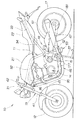
図2は本発明に係る自動二輪車の要部側面図であり、メインフレーム32の後部下部にピボット軸61でスイングアーム51を取付け、このスイングアーム51の上部に左右の起立壁62,62(手前側の符号62のみ示す。)を設け、これらの起立壁62,62にクロス部材としてのクッションブラケット63を渡し、このクッションブラケット63にリヤクッションユニット52の上端部を取付け、このリヤクッションユニット52の下端部をリンク機構53を介してメインフレーム32の下端側に取付けたことを示す。なお、65はメインフレーム32の下端にリンク機構53を連結する連結部材である。
上記した起立壁62,62及びクッションブラケット63は、リヤクッションユニット52を支持する上端支持部材60を構成する部材である。
【0023】
リヤクッションユニット52は、内部にピストン(不図示)を移動可能に収納したシリンダ66と、ピストンに一端を取付けるとともにシリンダ66外に延ばしたピストンロッド67と、このピストンロッド67の他端に設けた下端取付部材68と、シリンダ66の上端に設けた上端取付部材71と、シリンダ66の外面に設けた上部スプリング受け72及び下端取付部材68に設けた下部スプリング受け73のそれぞれの間に介在させた懸架スプリング74と、シリンダ66の上部にリザーブタンク接続ホース76を介して接続したリザーブタンク(不図示。詳細は後述する。)とからなり、上端取付部材71をクッションブラケット63に取付け、下端取付部材68をリンク機構53に連結する。
【0024】
リヤクッションユニット52は、スイングアーム51が下方にスイングして、ピストンロッド67がシリンダ66内の油室に進入すると、油室内の容積が減少するため、油室内のオイルを別の油室としてのリザーブタンクへ流して蓄え、また、スイングアーム51が上方にスイングして、ピストンロッド67がシリンダ66内の油室から外部へ退出すると、油室の容積が増加するため、リザーブタンク内に蓄えておいたオイルをシリンダ66内の油室へ戻す機能を有する。
【0025】
また、リヤクッションユニット52は、プリロード操作部(不図示。詳細は後述する。)を操作することで懸架スプリング74のプリロードを調整するプリロード調整機構(不図示。詳細は後述する。)を付設したものであり、シリンダ66の上部にスプリングプリロード調整用油圧チューブ77(以下、「プリロード調整用チューブ77」と記す。)を介してプリロード操作部を接続する。
【0026】
リンク機構53は、スイングアーム51の下部に設けた下部取付部81に一端を取付けた第1リンク82と、この第1リンク82の他端に取付けるとともに一端をリヤクッションユニット52の下端取付部材68に連結し且つ他端をメインフレーム32側の連結部材65に連結した第2リンク83とからなる。なお、85,86,87、88は連結ピンである。
【0027】
図3は本発明に係る自動二輪車の要部平面図であり、スイングアーム51の前部に車体前後方向に長い長穴状の貫通穴91を開け、この貫通穴91の左右上部に起立壁62,62を設け、これらの起立壁62,62にクッションブラケット63を渡してボルト92…(…は複数個を示す。以下同じ。)で取付け、クッションブラケット63にリヤクッションユニット52の上端取付部材71をスイング可能に取付け、クッションブラケット63の後方からリザーブタンク接続ホース76を立ち上げ、このリザーブタンク接続ホース76を、スイングアーム51の前部側部上方に取付けたリザーブタンク93に接続し、クッションブラケット63の前方からプリロード調整用チューブ77を立ち上げたことを示す。なお、95はスイングアーム51の前端に取付けたピボット部としての取付パイプ、96はクッションブラケット63に上端取付部材71を固定するためのナットである。
図に示すように、クッションブラケット63は起立壁62,62に側方からボルト92…で取付けることで、組付作業性を向上させることができる。
【0028】
図2に戻って、貫通穴91は、上方側が開くテーパ部91aを上部に設けたものであり、このテーパ部91aによって、シリンダ66におけるリザーブタンク接続ホース76の接続部が貫通穴91の内面に干渉するのを確実に防止することができ、また、このテーパ部91aは、貫通穴91の上部のみに形成したものであるから、貫通穴91の全体が大径にならず、スイングアーム51の剛性の確保を容易に行うことができる。
尚、リヤクッションユニット52の上端部には、リヤクッションユニット52に取付けたストロークセンサの信号を出力する導線を接続してもよい。
【0029】
図4は本発明に係る自動二輪車のリヤクッションユニット上部とプリロード調整機構とを示す断面図であり、リヤクッションユニット52の上端取付部材71は、クッションブラケット63にねじ結合させた筒状のケース101と、このケース101内に収納した外輪102と、この外輪102をケース101内に固定するためにケース101の内面にねじ結合した外輪固定ナット103と、外輪102の内面を滑る内輪104と、この内輪104をシリンダ66の端部にスペーサ106を介して固定するための内輪固定ボルト107とからなる。
【0030】
上記した外輪102は、筒状部材の内面を凹状の球面の一部として形成するとともに同形状の外輪半体102a,102aを隣接させたものであり、内輪104は、筒状部材の外面を凸状の球面の一部として形成したものである。
これらの外輪102及び内輪104は、球面滑り軸受108を構成するものである。なお、111は外輪102と内輪104との摺動部に土埃等が付着するのを防止するダストシールである。
【0031】
プリロード調整機構114は、プリロード操作部115と、このプリロード操作部115にプリロード調整用チューブ77を介して接続した動作部116とからなり、懸架スプリング74(図2参照)のプリロード、即ち、リヤクッションユニット52(図2参照)の全長(図2における上端取付部材71と下端取付部材68との取付長さである。)を所定長さに設定した場合の、懸架スプリング74の荷重を調整する、換言すれば、懸架スプリング74の取付長さを調整するものである。
例えば、自動二輪車10(図1参照)の乗員が、1名から2名になった場合に、プリロードを大きくすることで車体の沈み込みを抑える。
【0032】
プリロード操作部115は、シリンダ部118と、このシリンダ部118内に移動可能に収納したピストン121と、このピストン121に一端を回転可能に取付けたボルト部材122と、このボルト部材122の他端にビス123で取付けた調整つまみ124と、シリンダ部118の開口部を塞ぐためにシリンダ部118にねじ結合させ且つボルト部材122にねじ結合させた端部密封部材126とからなる。127はシリンダ部118とピストン121とでできる油室である。
【0033】
端部密封部材126は、側面に穴部128を設け、この穴部128にスプリング131及びボール132を収納したものであり、調整つまみ124の内面に設けた凹部124a…にボール132をスプリング131で押し当てることで、シリンダ部118側に対して調整つまみ124をステップ状に回転させる、即ち調整つまみ124の回転時にクリック感を与える。なお、133はOリングである。
【0034】
動作部116は、シリンダ66に軸方向移動可能に取付けた上部スプリング受け72とシリンダ66との間に設けた油室66a、この油室66aに連通するようにシリンダ66の第1側部突出部66bに設けた油路66c、この油路66cを絞る絞り弁66dからなる。なお、135,136はOリング、137はシリンダ66の上端部にリザーブタンク接続ホース76を接続するためにシリンダ66から側方へ突出させた第2側方突出部である。
【0035】
以上に述べたプリロード調整機構114の作用を次に説明する。
調整つまみ124を手で回すと、調整つまみ124と一体にボルト部材122が回転し、ボルト部材122に設けたおねじ122aと端部密封部材126に設けためねじ126aとのねじ結合によってピストン121が図の位置から下降する。
【0036】
これにより、シリンダ部118内の油室127内に満たしたオイルは、プリロード調整用チューブ77を通り、油路66cを通って油室66aに至り、油室66aの容積を増加させる。
【0037】
この結果、上部スプリング受け72がシリンダ66に対して下方に移動することで、懸架スプリングの取付長さを短くして、懸架スプリングのプリロードを上げることができる。
【0038】
図4に戻って、調整つまみ124を上記したのとは逆の方向に回せば、ピストン121が上昇し、油室66a内のオイルは、油路66c及びプリロード調整用チューブ77を通って油室127内に至るため、油室66a内の容積は減少し、上部スプリング受け72がシリンダ66に対して上方に移動することで、懸架スプリングの取付長さを長くして、懸架スプリングのプリロードを下げることができる。
【0039】
図5は本発明に係る自動二輪車のスイングアームの側面図であり、スイングアーム51において、前端に取付パイプ95を取付け、取付パイプ95を含む前部上部に起立壁62,62を取付け、下部に下部取付部81を取付け、後端に後輪17(図1参照)の車軸を取付けるための車軸取付部としての車軸取付穴52aを開けたことを示す。なお、62a,62aは起立壁62,62にクッションブラケット63(図2参照)を取付けるためにボルト92,92(図3参照)を通すボルト挿通穴である。
【0040】
図6は本発明に係る自動二輪車のスイングアームの平面図であり、スイングアーム51は、前部に設けた平面視がほぼ台形状のベース部141と、このベース部141から一体に後方へ延ばした左右のアーム部142,143と、ベース部141に取付けた取付パイプ95、起立壁62,62及び下部取付部81(図5参照)とからなり、ベース部141に貫通穴91を開けた部材である。
【0041】
以上の図5及び図6に示したように、起立壁62,62をベース部141に加え取付パイプ95にまで取付けたことで、起立壁62,62を強固に取付けることができるとともに、スイングアーム51の剛性を高めることができるから、所定の剛性を得る場合にはスイングアーム51をより軽量にすることができる。
【0042】
図7は図6の7−7線断面図であり、スイングアーム51は、上面を形成するとともに起立壁62,62を一体成型した上部プレート部材145と、貫通穴91を形成する筒部材146と、下面を形成する下部プレート部材147と、これらの上部プレート部材145及び下部プレート部材147の左・右側面を形成する左部プレート部材148及び右部プレート部材151と、左部プレート部材148とで角パイプを形成する断面コ字状とした左コ字部材152と、右部プレート部材151とで角パイプを形成する断面コ字状とした右コ字部材153とを溶接にて接合したものである。
【0043】
図8は本発明に係る自動二輪車のスイングアームの前端部を示す断面図(一部平面図)であり、取付パイプ95の中空部95aの両端部にそれぞれ球面滑り軸受161、161を挿入し、これらの球面滑り軸受161,161間の距離を一定に保つために中空部95a内にインナパイプ162を挿入し、球面滑り軸受161,161が中空部95aから抜けないように止め輪163,163で抜け止めを図り、球面滑り軸受161,161の外側にカラー164,164を隣接させ、これらの球面滑り軸受161,161内、インナパイプ162内、カラー164,164内及びメインフレーム32に設けた取付穴32a,32a内にボルトからなるピボット軸61を挿入し、ピボット軸61の先端に形成したおねじにナットをねじ込むことで、左右のメインフレーム32,32にスイングアーム51を取付けることを示す。なお、165,165はダストシールである。
【0044】
球面滑り軸受161は、取付パイプ95に嵌合させた外輪167と、この外輪167に外面を摺動自在に嵌合させるとともに内面をピボット軸61に嵌合させた内輪168とからなる。
【0045】
図9は本発明に係る自動二輪車の排気装置を示す平面図であり、排気装置46は、シリンダヘッド45(図1参照)に各気筒毎に取付ける第1排気管171、第2排気管172、第3排気管173及び第4排気管174と、第1排気管171及び第2排気管172に連結した左集合管176と、この左集合管176の後端に連結した左触媒取付管177と、この左触媒取付管177の後端に取付けた左後部排気管178と、この左後部排気管178の後端に連結した左マフラ181と、第3排気管173及び第4排気管174に連結した右集合管183と、この右集合管183の後端に連結した右触媒取付管184と、この右触媒取付管184の後端に連結した右後部排気管186と、この右後部排気管186の後端に取付けた右マフラ187と、前述の左集合管176及び右集合管183のそれぞれを連通させる前連通管188と、左後部排気管178及び右後部排気管186のそれぞれを連通させる後連通管191とからなる直列4気筒エンジン用のものである。
【0046】
図10は本発明に係る自動二輪車の触媒取付管の断面図であり、図9に示した左触媒取付管177について説明する。なお、右触媒取付管184は左触媒取付管177と同一構造である。
左触媒取付管177は、管部193と、この管部193内に収納した触媒194と、これらの管部193及び触媒194のそれぞれの間に設けた環状のスペーサ195,195とからなり、管部193の両端を絞ることでスペーサ195,195を介して触媒194を保持する。なお、195aはスペーサ195の内周端部に形成した段部であり、触媒194の端部194aに当てる部分である。
【0047】
スペーサ195は、ステンレス鋼製のワイヤを編んで形成したほぼ筒状の部材であり、弾性を有するものである。
即ち、スペーサ195によって、管部193内で触媒194を弾性的に保持するため、触媒194が熱膨張するときや管部193を絞るときに触媒194に作用する外力を緩和する。
尚、スペーサ195としては、セラミックス製の繊維で形成したものでもよい。
【0048】
図11は本発明に係る自動二輪車のマフラを示す断面図であり、図9に示した左マフラ181について説明する。なお、右マフラ187については、左マフラ181と同一構造である。
左マフラ181は、入口管198と、この入口管198の後部に一体的に形成した中間部管201と、この中間部間201の後部に一体的に形成した後部管202と、中間部管201に連結した外筒203とからなる。
入口管198は、排気圧を調整するための排気バルブ(不図示)を回転可能に取付けるバルブ取付部205を設けた部分である。
【0049】
中間部管201は、二重管であり、通気穴206a…を開けた内管206と、この内管206の外側に設けた外管207とからなり、内管206と外管207との間に形成した環状室208にステンレス鋼を繊維状にしたステンレスウールを詰めた部分である。
【0050】
このようなステンレスウールによって、内管206内から通気穴206a…を通して環状室208内に進入した排気ガスを保温し、内管206を通過する排気ガスの温度が低下するのを防止する。
【0051】
後部管202は、触媒211を収納した部分であり、管部212と、触媒211と、これらの触媒211及び管部212のそれぞれの間に設けたスペーサ213,213とからなり、スペーサ213は図10に示したスペーサ195と同一材料、同一構造であり、管部212を絞ることで、スペーサ213,213を介して触媒211を弾性的に保持する。なお、215は管部212の後端に開けた管部出口である。
中間部管201で温度の低下が抑えられた排気ガスは、この後部管202内で高い温度で触媒211と接触するため、触媒反応を促進させることができる。
【0052】
以上に述べた左触媒取付管177の組立要領を次に説明する。
図12は本発明に係る自動二輪車の触媒取付管の組立要領を示す作用図であり、左触媒取付管177で組立要領の流れを説明する。なお、STXXはステップ番号を示す。
ST01…触媒にスペーサを嵌合する。即ち、円柱状の触媒194の端部194a,194a側からスペーサ195を触媒194の外周部194bに嵌合し、触媒組立体217を造る。
【0053】
この場合の嵌合は、触媒194の外径D3に対してスペーサ195の内径D4を小さくしておくことで、スペーサ195を弾性力によって触媒195に圧入するものである。従って、圧入後はスペーサ195は触媒194から外れにくく次の作業がし易い。
【0054】
ST02…管部に触媒組立体を嵌合する。即ち、真直ぐな管部193AにST01で造った触媒組立体217を挿入し、位置決めする。
この場合の嵌合は、すきま嵌め又は圧入である。
【0055】
ST03…管部を絞る。即ち、管部193Aの両端部を絞って、絞り後の管部193で触媒194を弾性的に保持する。
【0056】
このように、触媒194をスペーサ195を介して弾性保持することで、絞り加工時に触媒194の端部194aと外周部194bとの角部が損傷することを防止することができ、また、触媒194の熱膨張をスペーサ195で吸収することができ、しかも触媒194が低温下で収縮した場合でも触媒194が管部193内でがたつく心配がない。管部193Aの両端部は、片側ずつ絞ってもよいし、同時に絞ってもよい。両方を同時に絞れば、製造工数を少なくすることができ、生産性を高めることができる。
【0057】
以上に述べた前連通管188の作用を次に説明する。
図13は本発明に係る自動二輪車の連通管の作用を示す作用図である。
エンジンから左集合管176に流れた排気ガスのほとんどは、通常は左触媒取付管177の触媒195を通過して左後部排気管178に流れる。
また、エンジンから右集合管183に流れた排気ガスほとんどは、通常は右触媒取付管184の触媒195を通過して右後部排気管186に流れる。
【0058】
例えば、右触媒取付管184側の触媒195が左触媒取付管177側の触媒195よりもカーボンで汚れて通気性が低下したときには、右集合管183内の排気ガスの一部は、前連通管188を通って左集合管176に至り、左触媒取付管177の触媒195を通過して左後部排気管178に流れる。
【0059】
反対に、左触媒取付管177側の触媒195が右触媒取付管184側の触媒195よりもカーボンで汚れて通気性が低下したときには、左集合管176内の排気ガスの一部は、前連通管188を通って右集合管183に至り、右触媒取付管184の触媒195を通過して右後部排気管186に流れる。
【0060】
このように、排気装置46は、触媒195の汚れによって生じる左右の排気管の排気圧の差を前連通管188によって小さくして排気圧の最大値を下げることができ、所望の出力特性を長期に亘って維持することができる。また、前連通管188は、左集合管176と右集合管183との間に傾斜させて取付け、この傾斜の度合いを変更することで、前連通管188の管長を調整することができ、エンジンの出力特性を向上させることができる。
【0061】
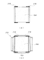
図14(a),(b)は本発明に係る自動二輪車の触媒取付管の変形例を示す断面図である。
(a)は、触媒194に嵌合させた筒状のスペーサ218,218を示す。
スペーサ218は、ステンレス鋼製のワイヤを編んで形成した部材であり、触媒194を弾性的に保持する
【0062】
(b)は触媒194及びスペーサ218,218を管部に挿入して管部の両端を絞り、触媒取付管219を形成したことを示す。
筒状であったスペーサ218は、絞った後の管部193の内面に沿うように端部が内側へ折れ曲がり、触媒194の角部を回り込むように弾性保持する。
【0063】
図15は本発明に係る自動二輪車のエアクリーナを示す断面図であり、エアクリーナ56は、燃料タンク21の底板21aとこの底板21aの下方を覆うように底板21aに取付けたケース半体221とからエアクリーナケース222を形成し、このエアクリーナケース222内に設けたエアファンネル223をフィルタ224で覆い、ケース半体221の前部に吸気口55を取付けたものである。
【0064】
なお、226はエンジン14のシリンダヘッド45に取付けたインテークマニホールド、227はインテークマニホールド226に取付けるとともに前述のエアファンネル223の取付部となる吸気管、228は吸気管227に取付けたフューエルインジェクタである。
【0065】
このように、燃料タンク21の底板21aをエアクリーナケース222の一部とすることで、燃料タンク21の下方のスペースを有効に利用することができ、自動二輪車10(図1参照)をスリムに構成することができ、また、エアクリーナケース222の重量を軽減することができる。
【0066】
図16は本発明に係る自動二輪車のホイールの断面図であり、後輪17を構成するホイールについて説明する。
ホイール231は、車軸232側に取付けたハブ233と、このハブ233から径外方にほぼ放射状に延ばした複数のスポーク234と、これらのスポーク234の先端に設けたリム236とからなる。
【0067】
ハブ233は、開口237を有する凹部238を設けたハブ本体239と、開口237を塞ぐ側壁部材としてのラバー支持部材267と、このラバー支持部材267をハブ本体239に取付ける複数のボルト242と、ハブ本体239及びラバー支持部材267内に配置したアウタカラー247とからなる。
上記したハブ本体239、スポーク234及びリム236は、一体構造の鍛造製のホイール本体241を構成するものである。
【0068】
以下にホイール231の支持構造を説明する。
ホイール231を支持するには、ハブ本体239とホイールダンパ243(詳細は後述する。)を構成するラバー支持部材267とを備えたハブ233を第2ベアリングとしての左ベアリング244及び第1ベアリングとしての右ベアリング245を介して車軸232に回転可能に取付け、左・右ベアリング244,245間に、左・右ベアリング244,245の距離を一定に保つインナカラー246を配置し、ラバー支持部材267と右ベアリング245との間にアウタカラー247を配置する。
【0069】
このように、ハブ本体239とアウタカラー247とを別体としたことで、従来ハブとアウタカラーとが一体であったのに比べて、本発明ではハブ本体239の鍛造による加工性、特に凹部238内の加工性を向上させることができ、生産性を高めることができる。
【0070】
図中の251はディスクブレーキ装置用のブレーキディスク、252は車軸232にベアリング253で回転可能に取付けたスプロケット支持部材、254はスプロケット支持部材252にボルト255及びナット256で取付けたドリブンスプロケット、257,258はダストシール、261は右ベアリング245を圧入し且つアウタカラー247を嵌めるためにハブ233の底部に設けたハブ本体穴、262は右ベアリング245の抜け止めを行う止め輪である。
【0071】
ホイールダンパ243は、図1に示したエンジン14及び変速機15からチェーン47及び図16に示すドリブンスプロケット254を介してホイール231に駆動力を伝達するときに、ドリブンスプロケット254からホイール231に過度の衝撃が伝わらないように衝撃を緩和する装置であり、スプロケット支持部材252に設けた複数の突出部265と、これらの突出部265に隣接させたラバー片266と、このラバー片266を支持するラバー支持部材267とからなり、駆動力は、ドリブンスプロケット254→スプロケット支持部材252→突出部265→ラバー片266→ラバー支持部材267→ハブ本体239のように伝わる。
ドリブンスプロケット254に衝撃的な駆動力が伝われば、この衝撃はラバー片266が突出部265で押圧されて縮むことにより吸収される。
【0072】
ここで、271はラバー支持部材267の角部272に突き当てるためにアウタカラー247の一端部273に設けた段部、274はハブ本体穴261に嵌めるためのアウタカラー247の他端部、275は左ベアリング244を圧入するとともにアウタカラー247の段部271の先端部を嵌めるためにラバー支持部材267に設けた側壁穴としての支持部材穴である。
【0073】
以上に述べたホイール231の車軸232への組付け要領を図17〜図19で説明する。
図17は本発明に係るホイールの組付け要領を示す第1作用図である。
まず、ラバー支持部材267をボルト242でハブ本体239の開口237側に取付ける。この結果、ハブ本体239とラバー支持部材267とからハブ組立体278が出来る。
【0074】
図18(a),(b)は本発明に係るホイールの組付け要領を示す第2作用図である。
(a)において、アウタカラー247をハブ本体239のハブ本体穴261からハブ組立体278内に挿入し、アウタカラー247の段部271をラバー支持部材267の角部272に突き当てる。
【0075】
(b)において、右ベアリング245を、アウタカラー247の他端部274に突き当たるまでハブ本体穴261に圧入する。
このとき、アウタカラー247がラバー支持部材267に突き当たった状態にあるため、右ベアリング245の圧入荷重をアウタカラー247を介してラバー支持部材267で受けることができ、ハブ233が変形することを防止することができる。
更に、止め輪262をハブ本体穴261に形成した環状溝261aに嵌める。
【0076】
図19(a),(b)は本発明に係るホイールの組付け要領を示す第3作用図である。
(a)において、インナカラー246をラバー支持部材267の支持部材穴275からアウタカラー247内に挿入し、インナカラー246の先端を右ベアリング245に突き当てる。
(b)において、左ベアリング244を、インナカラー246に突き当たるまで支持部材穴275に圧入する。
【0077】
そして、図16において、予めベアリング253を圧入するとともにドリブンスプロケット254を取付けたスプロケット支持部材252を、ラバー支持部材267の側部に結合させ、スプロケット支持部材252の端部にダストシール257を嵌め、ハブ本体239の端部にダストシール258を嵌め、車軸232をベアリング253内、左ベアリング244内、インナカラー246内及び右ベアリング245内に順に通す。
これで、車軸232へのホイール231の組付けが完了する。
【0078】
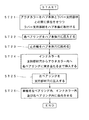
図20は本発明に係るホイールの組付け方法を示すフロー図であり、図17〜図19で示したホイールの組付け要領に基づいて再度説明する。STXXはステップ番号を示す。
ST11…ラバー支持部材をハブ本体に取付ける。
【0079】
ST12…アウタカラーをハブ本体穴からハブ組立体内へラバー支持部材に突き当たるまで挿入する。
ST13…右ベアリングをハブ本体穴に圧入する。
ST14…止め輪をハブ本体穴に嵌める。
【0080】
ST15…インナカラーを支持部材穴からアウタカラー内へ右ベアリングに突き当たるまで挿入する。
ST16…左ベアリングを支持部材穴に圧入する。
ST17…車軸を左ベアリング内、インナカラー内及び右ベアリング内に嵌合させる。
以上で、ホイールの組付け方法が完了する。
【0081】
図21は本発明に係るホイールにおけるアウタカラーの変形例を示す断面図であり、内面281に環状に突部282を設けたアウタカラー283を示す。
このように、アウタカラー283の内面に突部282を設けることで、アウタカラー283内に挿入したインナカラー246をアウタカラー283の横断面中央付近に配置することができ、インナカラー246内へ車軸232(図16参照)をより通し易くすることができる。
【0082】
図22は本発明に係る自動二輪車のホイールの別の実施の形態を示す断面図であり、図16に示した実施の形態と同一構成については同一符号を付け、詳細説明は省略する。
ホイール285は、車軸232側に取付けたハブ286を備える。
ハブ286は、ハブ本体287と、このハブ本体287の開口237を塞ぐ側壁部材としてのラバー支持部材288と、このラバー支持部材288をハブ本体287に取付ける複数のボルト242と、ハブ本体287及びラバー支持部材288内に配置したアウタカラー289とからなる。
【0083】
ハブ本体287は、アウタカラー289の一端部291を挿入する環状溝292を内面に形成したものであり、ラバー支持部材288は、アウタカラー289の他端部293を挿入する環状溝294を内面に形成したものである。
上記したハブ本体287、スポーク234及びリム236は、一体構造の鍛造製のホイール本体295を構成するものである。
【0084】
次に、上記のホイール285の車軸232への組付け要領を説明する。
まず、アウタカラー289の一端部291をハブ本体287の環状溝292に挿入するとともにアウタカラー289の他端部293をラバー支持部材288の環状溝294に挿入しながら、ラバー支持部材288をボルト242でハブ本体287の開口237側に取付ける。この結果、ハブ本体287とラバー支持部材288とアウタカラー289とからハブ組立体296が出来る。
【0085】
次に、右ベアリング245を、ハブ本体287の底部に開けたハブ本体穴297に圧入する。
更に、止め輪262をハブ本体穴297に形成した環状溝298に嵌める。
【0086】
そして、インナカラー246をラバー支持部材288の中央部に開けた側壁穴としての支持部材穴301からアウタカラー289内に挿入し、インナカラー246の先端を右ベアリング245に突き当てる。
更に、左ベアリング244を、インナカラー246に突き当たるまで支持部材穴301に圧入する。
【0087】
そして、図16において、予めベアリング253及びドリブンスプロケット254を取付けたスプロケット支持部材252を、ラバー支持部材288の側部に結合させ、スプロケット支持部材252の端部にダストシール257を嵌め、ハブ本体287の端部にダストシール258を嵌め、車軸232をベアリング253内、左ベアリング244内、インナカラー246内及び右ベアリング245内に順に通す。
これで、車軸232へのホイール285の組付けが完了する。
【0088】
図23は本発明に係るホイールの別の実施の形態の組付け方法を示すフロー図であり、図22で示したホイールの組付け要領に基づいて再度説明する。STXXはステップ番号を示す。
ST21…アウタカラーをハブ本体とラバー支持部材との間に係合させつつ、ラバー支持部材をハブ本体に取付ける。
【0089】
ST22…右ベアリングをハブ本体穴に圧入する。
ST23…止め輪をハブ本体穴に嵌める。
ST24…インナカラーを支持部材穴からアウタカラー内へ右ベアリングに突き当たるまで挿入する。
【0090】
ST25…左ベアリングを支持部材穴に圧入する。
ST26…車軸を左ベアリング内、インナカラー内及び右ベアリング内に嵌合させる。
以上で、ホイールの組付け方法が完了する。
【0091】
図24は本発明に係る自動二輪車のステップ支持構造を示す側面図(矢印(front)は車体前方を表す。)であり、メインフレーム32の後部下部にステップホルダ321を取付け、このステップホルダ321にボルト315でステップ322を取付け、ボルト315のステップ322より内側にブレーキペダル323をスイング可能に取付けたことを示す。
【0092】
ステップホルダ321は、メインフレーム32に取付けるための上部アーム部321a及び下部アーム部321bと、右マフラ187を取付けるための後部延出部321cとを備える。
【0093】
ブレーキペダル323は、ボルト315に軸受を介して取付けた基部323aと、前端に設けた踏み込み部323bと、後端に設けたシリンダ連結部323cとからなり、シリンダ連結部323cをマスタシリンダ325に連結する。
【0094】
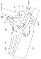
図25は図24の25−25線断面図であり、ブレーキペダル323にマスタシリンダ325を連結するための連結部材327は、ブレーキペダル323のシリンダ連結部323c(図24参照)に取付けた延長部材328と、この延長部材328及びマスタシリンダ325のロッド先端部材331に挿入したボルト332と、このボルト332の端部にねじ込んだナット333と、ボルト332の途中であって延長部材328とロッド先端部材331との間に設けた止め輪334とからなる。
ロッド先端部材331は、マスタシリンダ325内のピストンから延ばしたロッド336に取付けた部材である。
【0095】
337は、連結部材327をステップホルダ321に貫通させるためにステップホルダ321に設けた挿通穴である。
【0096】
尚、本発明の図22に示した実施の形態では、アウタカラー289を、外径がほぼ一様な筒状としたが、これに限らず、例えば、中央部の外径を大きくした筒状の大径部とし、この大径部の両側の外径をこの大径部より小さくした筒状の小径部とし、各小径部をハブ本体穴261と支持部材穴301とにそれぞれ嵌合させ、大径部と小径部との境に出来る軸に直交する面をハブ本体287とラバー支持部材288とにそれぞれ当ててもよい。
【0097】
【発明の効果】
本発明は上記構成により次の効果を発揮する。
請求項1のホイール構造は、ハブ本体穴からハブ内にインナカラーを囲む筒状のアウタカラーを挿入することで、側壁部材にアウタカラーを介して第1ベアリングを当てたので、第1ベアリングをハブ本体穴に圧入するときに、第1ベアリングに加える圧入荷重をアウタカラーを介して側壁部材で支えることができる。従って、例えば、従来のようにアウタカラーを備えず、ベアリングの圧入荷重のほとんどをハブで受けるものに比べて、本発明では、ハブの剛性を高めることができ、ハブ本体の変形を抑えることができる。
【0098】
また、アウタカラーで第1ベアリングと側壁部材とを連結することで、ハブ本体と側壁部材とを車軸寄りの位置で連結することになり、ハブの剛性を高めることができる。従って、車両走行中にハブに作用する、より大きな荷重を支えることができる。
【0099】
請求項2のホイール組付け方法は、ハブ本体に側壁部材を結合し、ハブ本体の底部に開けたハブ本体穴からハブ本体内に筒状のアウタカラーを挿入するとともに、このアウタカラーの先端を側壁部材に突き当て、ハブ本体穴に第1ベアリングをアウタカラーの端部に突き当たるまで嵌合し、側壁部材の中央に開けた側壁穴からアウタカラー内に筒状のインナカラーを挿入するとともにインナカラーの先端を第1ベアリングに突き当て、側壁穴に第2ベアリングを嵌合させるとともに、第2ベアリングをインナカラーに突き当て、これらの第2ベアリング内、インナカラー内、第1ベアリング内に車軸を嵌合させるので、アウタカラーをハブ本体穴からハブ本体内に挿入することでアウタカラーをハブ内に容易に組み込むことができ、アウタカラーでハブの補強を容易に行うことができる。
【図面の簡単な説明】
【図1】 本発明に係るホイール構造を採用した自動二輪車の側面図
【図2】 本発明に係る自動二輪車の要部側面図
【図3】 本発明に係る自動二輪車の要部平面図
【図4】 本発明に係る自動二輪車のリヤクッションユニット上部とプリロード調整機構とを示す断面図
【図5】 本発明に係る自動二輪車のスイングアームの側面図
【図6】 本発明に係る自動二輪車のスイングアームの平面図
【図7】 図6の7−7線断面図
【図8】 本発明に係る自動二輪車のスイングアームの前端部を示す断面図(一部平面図)
【図9】 本発明に係る自動二輪車の排気装置を示す平面図
【図10】 本発明に係る自動二輪車の触媒取付管の断面図
【図11】 本発明に係る自動二輪車のマフラを示す断面図
【図12】 本発明に係る自動二輪車の触媒取付管の組立要領を示す作用図
【図13】 本発明に係る自動二輪車の連通管の作用を示す作用図
【図14】 本発明に係る自動二輪車の触媒取付管の変形例を示す断面図
【図15】 本発明に係る自動二輪車のエアクリーナを示す断面図
【図16】 本発明に係る自動二輪車のホイールの断面図
【図17】 本発明に係るホイールの組付け要領を示す第1作用図
【図18】 本発明に係るホイールの組付け要領を示す第2作用図
【図19】 本発明に係るホイールの組付け要領を示す第3作用図
【図20】 本発明に係るホイールの組付け方法を示すフロー図
【図21】 本発明に係るホイールにおけるアウタカラーの変形例を示す断面図
【図22】 本発明に係る自動二輪車のホイールの別の実施の形態を示す断面図
【図23】 本発明に係るホイールの別の実施の形態の組付け方法を示すフロー図
【図24】 本発明に係る自動二輪車のステップ支持構造を示す側面図
【図25】 図24の25−25線断面図
【図26】 従来のホイール構造を示す断面図
【図27】 従来のホイール組付け方法を示す作用図
【符号の説明】
231,285…ホイール、、232…車軸、233,286…ハブ、237…開口、239,287…ハブ本体、244…第2ベアリング(左ベアリング)、245…第1ベアリング(右ベアリング)、246…インナカラー、247,289…アウタカラー、261,297…ハブ本体穴、267,288…側壁部材(ラバー支持部材)、275,301側壁穴(支持部材穴)。[0001]
BACKGROUND OF THE INVENTION
The present invention relates to a wheel structure and a wheel assembly method for a motorcycle.
[0002]
[Prior art]
As a wheel structure of a motorcycle, a wheel damper that arranges the driven sprocket side and the hub side so as to be relatively rotatable and prevents an impact from being transmitted from the driven sprocket side to the hub side between the driven sprocket side and the hub side. The rear wheel provided is known. (For example, refer to Patent Document 1).
[0003]
[Patent Document 1]
Japanese Examined Patent Publication No. 8-25363 (page 2-3, Fig. 3)
[0004]
FIG. 3 of
FIG. 26 is a cross-sectional view showing a conventional wheel structure. A
[0005]
The procedure for assembling the rear wheel will be described with reference to FIG.
FIG. 27 is an operation diagram showing a conventional wheel assembling method.
When the rear wheel is assembled, first, the
[0006]
Then, as indicated by an arrow, the
[0007]
[Problems to be solved by the invention]
In FIG. 27, in order to press-fit the
[0008]
Further, the
[0009]
In order to increase the rigidity of the
[0010]
Therefore, an object of the present invention is to provide rigidity to a wheel having a hub that has a structure in which an opening provided at one end is closed with a side wall member so that it can sufficiently withstand a load applied during bearing press-fitting and a load applied during vehicle travel. An object of the present invention is to provide an improved wheel structure, and to provide a wheel assembling method in which the rigidity of the hub can be easily increased and cost increase can be suppressed.
[0011]
[Means for Solving the Problems]
In order to achieve the above object, the present invention provides a wheel hub comprising a cup-shaped hub body and a side wall member that closes an opening of the hub body, and the side wall member is integrally attached to the hub body.Open a hub body hole to press-fit the first bearing in the bottom of the hub body, open a side-wall hole to press-fit the second bearing in the center of the side wall member,A cylindrical inner collar that rotatably attaches the hub to the axle via a first bearing that directly supports the hub body and a second bearing that directly supports the side wall member, and maintains the distance between the first and second bearings. In the wheel structure that is fitted to the axle,By inserting a cylindrical outer collar that surrounds the inner collar into the hub from the hub body hole,Side wall memberAThe first bearing is applied through the Uta collar.
[0012]
When the first bearing is press-fitted into the hub body hole, the press-fitting load applied to the first bearing can be supported by the side wall member via the outer collar. Therefore, for example, the present invention can increase the rigidity of the hub and suppress the deformation of the hub body as compared with the conventional case in which the outer collar is not provided and most of the press-fitting load of the bearing is received by the hub. it can.
[0013]
Further, by connecting the first bearing and the side wall member with the outer collar, the hub main body and the side wall member are connected at a position closer to the axle, which also increases the rigidity of the hub. Therefore, it is possible to support a larger load acting on the hub while the vehicle is traveling.
[0014]
Claim 2Is a method of assembling a wheel having a hub composed of a cup-shaped hub main body and a side wall member that closes the opening of the hub main body to an axle, wherein the side wall member is coupled to the hub main body and is attached to the bottom of the hub main body. A cylindrical outer collar is inserted into the hub body through the opened hub body hole, the tip of the outer collar is abutted against the side wall member, and the first bearing is placed in the hub body hole.Until it hits the end of the outer collarThe cylindrical inner collar is inserted into the outer collar from the side wall hole opened in the center of the side wall member, the tip of the inner collar is abutted against the first bearing, and the second bearing is fitted into the side wall hole. The second bearing is abutted against the inner collar, and the axle is fitted in the second bearing, the inner collar, and the first bearing.
[0015]
By inserting the outer collar into the hub body through the hub body hole, the outer collar can be easily assembled into the hub, and the outer collar can easily increase the rigidity of the hub.The
[0016]
DETAILED DESCRIPTION OF THE INVENTION
Embodiments of the present invention will be described below with reference to the accompanying drawings. The drawings are viewed in the direction of the reference numerals.
FIG. 1 is a side view of a motorcycle adopting a wheel structure according to the present invention. A
[0017]
The vehicle body frame 11 includes a
[0018]
The front wheel suspension /
[0019]
The
The
[0020]
The
[0021]
The air cleaner 56 (not shown) provided integrally below the
[0022]
FIG. 2 is a side view of the main part of the motorcycle according to the present invention. A
The standing
[0023]
The
[0024]
In the
[0025]
Further, the
[0026]
The
[0027]
FIG. 3 is a plan view of the main part of the motorcycle according to the present invention. A long through
As shown in the figure, the
[0028]
Returning to FIG. 2, the through-
A lead wire that outputs a signal of a stroke sensor attached to the
[0029]
FIG. 4 is a cross-sectional view showing the upper part of the rear cushion unit and the preload adjusting mechanism of the motorcycle according to the present invention. The upper
[0030]
The
The
[0031]
The
For example, when the number of occupants of the motorcycle 10 (see FIG. 1) is changed from one to two, the sinking of the vehicle body is suppressed by increasing the preload.
[0032]
The
[0033]
The
[0034]
The operating
[0035]
Next, the operation of the
When the
[0036]
Thereby, the oil filled in the
[0037]
As a result, the
[0038]
Returning to FIG. 4, when the
[0039]
FIG. 5 is a side view of the swing arm of the motorcycle according to the present invention. In the
[0040]
FIG. 6 is a plan view of the swing arm of the motorcycle according to the present invention. The
[0041]
As shown in FIGS. 5 and 6, the
[0042]
7 is a cross-sectional view taken along line 7-7 of FIG. 6. The
[0043]
FIG. 8 is a cross-sectional view (partial plan view) showing the front end portion of the swing arm of the motorcycle according to the present invention. Spherical
[0044]
The spherical plain bearing 161 includes an
[0045]
FIG. 9 is a plan view showing an exhaust device for a motorcycle according to the present invention. The
[0046]
FIG. 10 is a cross-sectional view of the catalyst mounting pipe of the motorcycle according to the present invention, and the left
The left
[0047]
The
That is, the
The
[0048]
FIG. 11 is a cross-sectional view showing the muffler of the motorcycle according to the present invention, and the
The
The
[0049]
The
[0050]
With such stainless steel wool, the exhaust gas that has entered the
[0051]
The
Since the exhaust gas whose temperature drop is suppressed in the
[0052]
The procedure for assembling the left
FIG. 12 is an operation diagram showing the assembly procedure of the catalyst mounting tube of the motorcycle according to the present invention. The flow of the assembly procedure will be described with the left
ST01 ... Fit a spacer to the catalyst. That is, the
[0053]
The fitting in this case is to press-fit the
[0054]
ST02 ... The catalyst assembly is fitted into the pipe portion. That is, the
The fitting in this case is clearance fitting or press fitting.
[0055]
ST03 ... Squeeze the tube. That is, both ends of the
[0056]
Thus, by elastically holding the
[0057]
Next, the operation of the
FIG. 13 is an operation diagram showing the operation of the communication pipe of the motorcycle according to the present invention.
Most of the exhaust gas flowing from the engine to the
Most of the exhaust gas flowing from the engine to the
[0058]
For example, when the
[0059]
On the other hand, when the
[0060]
As described above, the
[0061]
14 (a) and 14 (b) are cross-sectional views showing modifications of the catalyst mounting pipe of the motorcycle according to the present invention.
(A) shows the
The
[0062]
(B) shows that the
The
[0063]
FIG. 15 is a cross-sectional view showing an air cleaner for a motorcycle according to the present invention. The
[0064]
[0065]
Thus, by making the
[0066]
FIG. 16 is a sectional view of a wheel of the motorcycle according to the present invention, and the wheel constituting the
The
[0067]
The
The
[0068]
The support structure of the
In order to support the
[0069]
As described above, the
[0070]
In the figure,
[0071]
When the
If a shocking driving force is transmitted to the driven
[0072]
Here, a
[0073]
The procedure for assembling the
FIG. 17 is a first operation view showing the way of assembling the wheel according to the present invention.
First, the
[0074]
18 (a) and 18 (b) are second operational views showing the procedure for assembling the wheel according to the present invention.
In (a), the
[0075]
In (b), the
At this time, since the
Further, the retaining
[0076]
FIGS. 19 (a) and 19 (b) are third action views showing the way of assembling the wheel according to the present invention.
In (a), the
In (b), the
[0077]
In FIG. 16, a
This completes the assembly of the
[0078]
FIG. 20 is a flowchart showing the method of assembling the wheel according to the present invention, and the description will be given again based on the wheel assembling procedure shown in FIGS. STXX indicates a step number.
ST11 ... A rubber support member is attached to the hub body.
[0079]
ST12 ... The outer collar is inserted into the hub assembly from the hub body hole until it hits the rubber support member.
ST13 ... Press-fit the right bearing into the hub body hole.
ST14 ... Fit the retaining ring into the hub body hole.
[0080]
ST15 ... Insert the inner collar from the support member hole into the outer collar until it hits the right bearing.
ST16 ... The left bearing is press-fitted into the support member hole.
ST17: The axle is fitted in the left bearing, the inner collar, and the right bearing.
This completes the wheel assembly method.
[0081]
FIG. 21 is a cross-sectional view showing a modified example of the outer collar in the wheel according to the present invention, and shows an
In this manner, by providing the
[0082]
FIG. 22 is a sectional view showing another embodiment of the wheel of the motorcycle according to the present invention. The same components as those in the embodiment shown in FIG.
The
The
[0083]
The hub
The
[0084]
Next, the procedure for assembling the
First, one
[0085]
Next, the
Further, the retaining
[0086]
Then, the
Further, the
[0087]
In FIG. 16, a
This completes the assembly of the
[0088]
FIG. 23 is a flowchart showing an assembling method of another embodiment of the wheel according to the present invention, which will be described again based on the assembling procedure of the wheel shown in FIG. STXX indicates a step number.
ST21 ... The rubber support member is attached to the hub body while the outer collar is engaged between the hub body and the rubber support member.
[0089]
ST22 ... Press-fit the right bearing into the hub body hole.
ST23 ... Fit the retaining ring into the hub body hole.
ST24 ... Insert the inner collar from the support member hole into the outer collar until it hits the right bearing.
[0090]
ST25 ... The left bearing is press-fitted into the support member hole.
ST26 ... The axle is fitted in the left bearing, the inner collar, and the right bearing.
This completes the wheel assembly method.
[0091]
FIG. 24 is a side view showing a step support structure of a motorcycle according to the present invention (an arrow (front) indicates the front of the vehicle body). A
[0092]
The
[0093]
The
[0094]
25 is a cross-sectional view taken along line 25-25 of FIG. 24. A connecting
The
[0095]
[0096]
In the embodiment shown in FIG. 22 of the present invention, the
[0097]
【The invention's effect】
The present invention exhibits the following effects by the above configuration.
The wheel structure of
[0098]
Further, by connecting the first bearing and the side wall member with the outer collar, the hub body and the side wall member are connected at a position closer to the axle, and the rigidity of the hub can be increased. Therefore, it is possible to support a larger load acting on the hub while the vehicle is traveling.
[0099]
Claim 2In this wheel assembly method, a side wall member is coupled to the hub body, a cylindrical outer collar is inserted into the hub body from a hub body hole opened in the bottom of the hub body, and the tip of the outer collar is used as the side wall member. Butt the first bearing in the hub body holeUntil it hits the end of the outer collarThe cylindrical inner collar is inserted into the outer collar from the side wall hole opened in the center of the side wall member, the tip of the inner collar is abutted against the first bearing, and the second bearing is fitted into the side wall hole. The second bearings are brought into contact with the inner collars, and the axles are fitted into the second bearings, the inner collars, and the first bearings. Therefore, the outer collars are inserted into the hub body through the hub body holes. The collar can be easily incorporated into the hub, and the outer collar can easily reinforce the hub.The
[Brief description of the drawings]
FIG. 1 is a side view of a motorcycle employing a wheel structure according to the present invention.
FIG. 2 is a side view of a main part of a motorcycle according to the present invention.
FIG. 3 is a plan view of the main part of the motorcycle according to the present invention.
FIG. 4 is a cross-sectional view showing an upper part of a rear cushion unit and a preload adjusting mechanism of a motorcycle according to the present invention.
FIG. 5 is a side view of a swing arm of a motorcycle according to the present invention.
Fig. 6 is a plan view of a swing arm of a motorcycle according to the present invention.
7 is a sectional view taken along line 7-7 in FIG.
FIG. 8 is a cross-sectional view (partial plan view) showing a front end portion of a swing arm of the motorcycle according to the present invention.
FIG. 9 is a plan view showing an exhaust device for a motorcycle according to the present invention.
FIG. 10 is a cross-sectional view of a catalyst mounting pipe of a motorcycle according to the present invention.
FIG. 11 is a cross-sectional view showing a muffler of a motorcycle according to the present invention.
FIG. 12 is an operation diagram showing the assembly procedure of the catalyst mounting pipe of the motorcycle according to the present invention.
FIG. 13 is an operation diagram showing the operation of the communication pipe of the motorcycle according to the present invention.
FIG. 14 is a cross-sectional view showing a modification of the catalyst mounting pipe of the motorcycle according to the present invention.
FIG. 15 is a cross-sectional view showing an air cleaner for a motorcycle according to the present invention.
FIG. 16 is a sectional view of a wheel of a motorcycle according to the present invention.
FIG. 17 is a first operation diagram showing a wheel assembly procedure according to the present invention.
FIG. 18 is a second action diagram showing the way of assembling the wheel according to the present invention.
FIG. 19 is a third action diagram showing the way of assembling the wheel according to the present invention.
FIG. 20 is a flowchart showing a method for assembling a wheel according to the present invention.
FIG. 21 is a sectional view showing a modification of the outer collar in the wheel according to the present invention.
FIG. 22 is a sectional view showing another embodiment of the wheel of the motorcycle according to the present invention.
FIG. 23 is a flowchart showing an assembling method of another embodiment of the wheel according to the present invention.
Fig. 24 is a side view showing a step support structure for a motorcycle according to the present invention.
25 is a sectional view taken along line 25-25 in FIG. 24.
FIG. 26 is a sectional view showing a conventional wheel structure.
FIG. 27 is an operation diagram showing a conventional wheel assembling method.
[Explanation of symbols]
231,285 ... wheel, 232 ... axle, 233,286 ... hub, 237 ... opening, 239,287 ... hub body, 244 ... second bearing (left bearing), 245 ... first bearing (right bearing), 246 ... Inner collar, 247, 289 ... outer collar, 261,297 ... hub body hole, 267,288 ... side wall member (rubber support member), 275,301 side wall hole (support member hole).
Claims (2)
前記ハブ本体穴から前記ハブ内に前記インナカラーを囲む筒状のアウタカラーを挿入することで、前記側壁部材に前記アウタカラーを介して前記第1ベアリングを当てたことを特徴とするホイール構造。A hub of a wheel is composed of a cup-shaped hub body and a side wall member that closes the opening of the hub body, the side wall member is integrally attached to the hub body, and a first bearing is press-fitted into the bottom of the hub body open the body bore, the opened side wall hole for press-fitting the second bearing in the center of the side wall member, through said second bearing for supporting the side wall member and the first bearing for supporting the hub body directly directly to the axle In the wheel structure in which the hub is rotatably attached to and the cylindrical inner collar that keeps the distance between the first and second bearings is fitted to the axle,
It said hub body bore from by inserting the cylindrical outer collar which surrounds the inner collar in the hub, the wheel structure being characterized in that against the first bearing via the front Kia Utakara the side wall member .
前記ハブ本体に側壁部材を結合し、
前記ハブ本体の底部に開けたハブ本体穴からハブ本体内に筒状のアウタカラーを挿入するとともに、このアウタカラーの先端を前記側壁部材に突き当て、
前記ハブ本体穴に第1ベアリングを前記アウタカラーの端部に突き当たるまで嵌合し、
側壁部材の中央に開けた側壁穴から前記アウタカラー内に筒状のインナカラーを挿入するとともにインナカラーの先端を第1ベアリングに突き当て、
前記側壁穴に第2ベアリングを嵌合させるとともに、第2ベアリングを前記インナカラーに突き当て、
これらの第2ベアリング内、インナカラー内、第1ベアリング内に車軸を嵌合させる、ことを特徴とするホイール組付け方法。 A method of assembling a wheel having a hub formed of a cup-shaped hub body and a side wall member that closes the opening of the hub body to an axle,
A side wall member is coupled to the hub body;
A cylindrical outer collar is inserted into the hub body from the hub body hole opened in the bottom of the hub body, and the tip of the outer collar is abutted against the side wall member,
Fit the first bearing into the hub body hole until it hits the end of the outer collar ,
A cylindrical inner collar is inserted into the outer collar from a side wall hole opened in the center of the side wall member, and the tip of the inner collar is abutted against the first bearing,
The second bearing is fitted into the side wall hole, and the second bearing is abutted against the inner collar,
Within these second bearing, the inner collar, wheel assembly Way Method of fitting the axle, characterized in that in the first bearing.
Priority Applications (7)
| Application Number | Priority Date | Filing Date | Title |
|---|---|---|---|
| JP2003074938A JP4108513B2 (en) | 2003-03-19 | 2003-03-19 | Wheel structure and wheel assembling method |
| TW093105307A TWI232813B (en) | 2003-03-19 | 2004-03-01 | Wheel rim structure and wheel rim mounting method |
| BRPI0400715-8A BRPI0400715B1 (en) | 2003-03-19 | 2004-03-16 | wheel structure and method of mounting a wheel to an axle. |
| IT000180A ITTO20040180A1 (en) | 2003-03-19 | 2004-03-17 | WHEEL STRUCTURE AND PROCEDURE FOR MOUNTING A WHEEL. |
| US10/802,750 US7097259B2 (en) | 2003-03-19 | 2004-03-18 | Wheel structure and wheel mounting method |
| DE102004013489A DE102004013489B4 (en) | 2003-03-19 | 2004-03-18 | Wheel hub and method for mounting a wheel |
| CNB2004100300750A CN1310776C (en) | 2003-03-19 | 2004-03-18 | Wheel structure and wheel assembling method |
Applications Claiming Priority (1)
| Application Number | Priority Date | Filing Date | Title |
|---|---|---|---|
| JP2003074938A JP4108513B2 (en) | 2003-03-19 | 2003-03-19 | Wheel structure and wheel assembling method |
Publications (2)
| Publication Number | Publication Date |
|---|---|
| JP2004276875A JP2004276875A (en) | 2004-10-07 |
| JP4108513B2 true JP4108513B2 (en) | 2008-06-25 |
Family
ID=32959476
Family Applications (1)
| Application Number | Title | Priority Date | Filing Date |
|---|---|---|---|
| JP2003074938A Expired - Fee Related JP4108513B2 (en) | 2003-03-19 | 2003-03-19 | Wheel structure and wheel assembling method |
Country Status (7)
| Country | Link |
|---|---|
| US (1) | US7097259B2 (en) |
| JP (1) | JP4108513B2 (en) |
| CN (1) | CN1310776C (en) |
| BR (1) | BRPI0400715B1 (en) |
| DE (1) | DE102004013489B4 (en) |
| IT (1) | ITTO20040180A1 (en) |
| TW (1) | TWI232813B (en) |
Families Citing this family (15)
| Publication number | Priority date | Publication date | Assignee | Title |
|---|---|---|---|---|
| US7472772B2 (en) * | 2003-02-20 | 2009-01-06 | Honda Motor Co., Ltd. | Structure for installing rear cushion |
| JP4130395B2 (en) * | 2003-09-09 | 2008-08-06 | 本田技研工業株式会社 | Swing arm suspension |
| US7210748B1 (en) * | 2005-03-15 | 2007-05-01 | Isaac Velazquez | Motorcycle hub adapter |
| JP2007118684A (en) * | 2005-10-26 | 2007-05-17 | Yamaha Motor Co Ltd | Wheel of motorcycle and its manufacturing method |
| JP4921801B2 (en) * | 2006-02-01 | 2012-04-25 | 本田技研工業株式会社 | Rear wheel suspension system for motorcycles |
| SI22709A (en) * | 2008-01-21 | 2009-08-31 | DIVERSE:INŽENIRING Gregor Bizjak s.p. | Wheel for high performance vehicles |
| US7896381B2 (en) * | 2008-03-20 | 2011-03-01 | Trek Bicycle Corporation | Bicycle wheel assembly |
| KR100925959B1 (en) * | 2008-08-06 | 2009-11-09 | 현대자동차주식회사 | Rear car body structure of vehicle |
| US7954905B2 (en) * | 2009-01-26 | 2011-06-07 | Salim Wakim | Modular motorcycle hub system |
| JP5261825B2 (en) * | 2009-03-31 | 2013-08-14 | 本田技研工業株式会社 | Saddle riding |
| ITMI20111985A1 (en) * | 2011-11-03 | 2013-05-04 | Pz5 S R L | HUB JOINT-FLANGED CROWN OF A MOTORCYCLE WHEEL. |
| ES2482567B2 (en) * | 2012-06-20 | 2015-04-30 | Fersa Innova, S.L.U. | Bearing assembly with safety bushing and insertion procedure |
| DE102018103367A1 (en) | 2018-02-15 | 2019-08-22 | Schaeffler Technologies AG & Co. KG | Bearing arrangement for a rear wheel of a motorcycle and rear wheel with the bearing assembly |
| DE102018108388A1 (en) | 2018-04-10 | 2019-10-10 | Schaeffler Technologies AG & Co. KG | Bearing arrangement for a rear wheel of a motorcycle and rear wheel with the bearing assembly |
| DE102018116438A1 (en) | 2018-07-06 | 2020-01-09 | Schaeffler Technologies AG & Co. KG | Bearing arrangement for a rear wheel of a motorcycle and rear wheel with the bearing arrangement |
Family Cites Families (11)
| Publication number | Priority date | Publication date | Assignee | Title |
|---|---|---|---|---|
| US1874192A (en) * | 1930-11-12 | 1932-08-30 | Kay Brunner Steel Products Inc | Hub construction for truck wheels |
| US4424981A (en) * | 1982-01-25 | 1984-01-10 | Maxwell Iii William H | High strength light weight bike axle |
| JPH0825363B2 (en) * | 1987-05-20 | 1996-03-13 | 本田技研工業株式会社 | Rear wheel of motorcycle |
| JPH01309801A (en) * | 1988-06-09 | 1989-12-14 | Yamaha Motor Co Ltd | Wheel having small diameter |
| US4880280A (en) * | 1988-06-27 | 1989-11-14 | Custom Chrome, Inc. | Motorcycle wheel hub and flange assembly |
| DE9113955U1 (en) * | 1991-11-09 | 1992-01-02 | Maschinenbau Wiedemann & Schmieding Gmbh, 4703 Boenen, De | |
| CN2148692Y (en) * | 1993-03-27 | 1993-12-08 | 胡锡华 | Anti-loosing hub unit apparatus for vehicle |
| US5757084A (en) * | 1995-09-15 | 1998-05-26 | Consolidated Metco, Inc. | Wheel hub assembly and method of installing a hub on an axle |
| US5992943A (en) * | 1997-07-17 | 1999-11-30 | Dana Corporation | Wheel end assembly |
| US6149244A (en) * | 1998-05-29 | 2000-11-21 | Consolidated Metco Inc. | Wheel hub assembly and method of installing a hub on an axle |
| US6591956B1 (en) * | 2002-04-29 | 2003-07-15 | Cane Creek Cycling Components, Inc. | Bicycle freewheel hub supported on a central drive cylinder |
-
2003
- 2003-03-19 JP JP2003074938A patent/JP4108513B2/en not_active Expired - Fee Related
-
2004
- 2004-03-01 TW TW093105307A patent/TWI232813B/en active
- 2004-03-16 BR BRPI0400715-8A patent/BRPI0400715B1/en not_active IP Right Cessation
- 2004-03-17 IT IT000180A patent/ITTO20040180A1/en unknown
- 2004-03-18 US US10/802,750 patent/US7097259B2/en not_active Expired - Fee Related
- 2004-03-18 DE DE102004013489A patent/DE102004013489B4/en not_active Expired - Fee Related
- 2004-03-18 CN CNB2004100300750A patent/CN1310776C/en not_active Expired - Fee Related
Also Published As
| Publication number | Publication date |
|---|---|
| BRPI0400715A (en) | 2005-01-11 |
| US20040222693A1 (en) | 2004-11-11 |
| ITTO20040180A1 (en) | 2004-06-17 |
| BRPI0400715B1 (en) | 2012-09-04 |
| DE102004013489A1 (en) | 2004-10-07 |
| CN1532077A (en) | 2004-09-29 |
| CN1310776C (en) | 2007-04-18 |
| DE102004013489B4 (en) | 2006-08-24 |
| TWI232813B (en) | 2005-05-21 |
| TW200422208A (en) | 2004-11-01 |
| US7097259B2 (en) | 2006-08-29 |
| JP2004276875A (en) | 2004-10-07 |
Similar Documents
| Publication | Publication Date | Title |
|---|---|---|
| JP4108513B2 (en) | Wheel structure and wheel assembling method | |
| EP1672241B1 (en) | Spacer for coil spring | |
| JP4523536B2 (en) | Vehicle air cleaner structure | |
| EP1880880A2 (en) | Vehicle | |
| US20050087947A1 (en) | Swing arm suspension | |
| JP4825715B2 (en) | Suspension arm support structure | |
| JP4994742B2 (en) | vehicle | |
| US20030015365A1 (en) | Motorcycle rear suspension swingarm assembly | |
| JP4467034B2 (en) | Motorcycle swing arm structure | |
| JP4467033B2 (en) | Swing arm type suspension system for motorcycles | |
| JP4303546B2 (en) | Motorcycle exhaust system | |
| JP2004278497A (en) | Catalyst fixing method and its fixing structure of exhaust device | |
| JP3170245B2 (en) | Motorcycle body frame | |
| JPH0413232Y2 (en) | ||
| JP2011256785A (en) | Exhaust device | |
| JPH0953441A (en) | Exhaust pipe equipped with exhaust emission control device | |
| JP6936421B1 (en) | Fluid supply device | |
| JP4520597B2 (en) | Bottom structure of hydraulic shock absorber | |
| US11535336B2 (en) | Saddle riding vehicle | |
| JP2019210864A (en) | Tail pipe structure of saddle riding type vehicle | |
| JPH09264130A (en) | Muffler structure for exhaust pipe | |
| JP4330784B2 (en) | Front fork | |
| JPH10132010A (en) | Buffer | |
| JPS63291785A (en) | Pressure chamber structure of front fork for motor bi- and tri-cycle | |
| JPS6233677Y2 (en) |
Legal Events
| Date | Code | Title | Description |
|---|---|---|---|
| A621 | Written request for application examination |
Free format text: JAPANESE INTERMEDIATE CODE: A621 Effective date: 20051201 |
|
| A977 | Report on retrieval |
Free format text: JAPANESE INTERMEDIATE CODE: A971007 Effective date: 20070531 |
|
| A131 | Notification of reasons for refusal |
Free format text: JAPANESE INTERMEDIATE CODE: A131 Effective date: 20070605 |
|
| A521 | Written amendment |
Free format text: JAPANESE INTERMEDIATE CODE: A523 Effective date: 20070803 |
|
| A131 | Notification of reasons for refusal |
Free format text: JAPANESE INTERMEDIATE CODE: A131 Effective date: 20071120 |
|
| A521 | Written amendment |
Free format text: JAPANESE INTERMEDIATE CODE: A523 Effective date: 20080116 |
|
| TRDD | Decision of grant or rejection written | ||
| A01 | Written decision to grant a patent or to grant a registration (utility model) |
Free format text: JAPANESE INTERMEDIATE CODE: A01 Effective date: 20080401 |
|
| A61 | First payment of annual fees (during grant procedure) |
Free format text: JAPANESE INTERMEDIATE CODE: A61 Effective date: 20080402 |
|
| FPAY | Renewal fee payment (event date is renewal date of database) |
Free format text: PAYMENT UNTIL: 20110411 Year of fee payment: 3 |
|
| R150 | Certificate of patent or registration of utility model |
Free format text: JAPANESE INTERMEDIATE CODE: R150 |
|
| FPAY | Renewal fee payment (event date is renewal date of database) |
Free format text: PAYMENT UNTIL: 20110411 Year of fee payment: 3 |
|
| FPAY | Renewal fee payment (event date is renewal date of database) |
Free format text: PAYMENT UNTIL: 20130411 Year of fee payment: 5 |
|
| FPAY | Renewal fee payment (event date is renewal date of database) |
Free format text: PAYMENT UNTIL: 20130411 Year of fee payment: 5 |
|
| FPAY | Renewal fee payment (event date is renewal date of database) |
Free format text: PAYMENT UNTIL: 20140411 Year of fee payment: 6 |
|
| LAPS | Cancellation because of no payment of annual fees |