JP4105744B2 - Supporting assembly - Google Patents
Supporting assembly Download PDFInfo
- Publication number
- JP4105744B2 JP4105744B2 JP2006507901A JP2006507901A JP4105744B2 JP 4105744 B2 JP4105744 B2 JP 4105744B2 JP 2006507901 A JP2006507901 A JP 2006507901A JP 2006507901 A JP2006507901 A JP 2006507901A JP 4105744 B2 JP4105744 B2 JP 4105744B2
- Authority
- JP
- Japan
- Prior art keywords
- bearing
- seat
- support
- sliding load
- bearing seat
- Prior art date
- Legal status (The legal status is an assumption and is not a legal conclusion. Google has not performed a legal analysis and makes no representation as to the accuracy of the status listed.)
- Expired - Fee Related
Links
Images


Classifications
-
- E—FIXED CONSTRUCTIONS
- E04—BUILDING
- E04B—GENERAL BUILDING CONSTRUCTIONS; WALLS, e.g. PARTITIONS; ROOFS; FLOORS; CEILINGS; INSULATION OR OTHER PROTECTION OF BUILDINGS
- E04B1/00—Constructions in general; Structures which are not restricted either to walls, e.g. partitions, or floors or ceilings or roofs
- E04B1/36—Bearings or like supports allowing movement
-
- E—FIXED CONSTRUCTIONS
- E01—CONSTRUCTION OF ROADS, RAILWAYS, OR BRIDGES
- E01D—CONSTRUCTION OF BRIDGES, ELEVATED ROADWAYS OR VIADUCTS; ASSEMBLY OF BRIDGES
- E01D19/00—Structural or constructional details of bridges
- E01D19/04—Bearings; Hinges
- E01D19/042—Mechanical bearings
- E01D19/046—Spherical bearings
-
- E—FIXED CONSTRUCTIONS
- E01—CONSTRUCTION OF ROADS, RAILWAYS, OR BRIDGES
- E01D—CONSTRUCTION OF BRIDGES, ELEVATED ROADWAYS OR VIADUCTS; ASSEMBLY OF BRIDGES
- E01D19/00—Structural or constructional details of bridges
- E01D19/04—Bearings; Hinges
-
- E—FIXED CONSTRUCTIONS
- E02—HYDRAULIC ENGINEERING; FOUNDATIONS; SOIL SHIFTING
- E02D—FOUNDATIONS; EXCAVATIONS; EMBANKMENTS; UNDERGROUND OR UNDERWATER STRUCTURES
- E02D27/00—Foundations as substructures
- E02D27/32—Foundations for special purposes
- E02D27/34—Foundations for sinking or earthquake territories
-
- E—FIXED CONSTRUCTIONS
- E04—BUILDING
- E04H—BUILDINGS OR LIKE STRUCTURES FOR PARTICULAR PURPOSES; SWIMMING OR SPLASH BATHS OR POOLS; MASTS; FENCING; TENTS OR CANOPIES, IN GENERAL
- E04H9/00—Buildings, groups of buildings or shelters adapted to withstand or provide protection against abnormal external influences, e.g. war-like action, earthquake or extreme climate
- E04H9/02—Buildings, groups of buildings or shelters adapted to withstand or provide protection against abnormal external influences, e.g. war-like action, earthquake or extreme climate withstanding earthquake or sinking of ground
- E04H9/021—Bearing, supporting or connecting constructions specially adapted for such buildings
Landscapes
- Engineering & Computer Science (AREA)
- Architecture (AREA)
- Structural Engineering (AREA)
- Civil Engineering (AREA)
- Environmental & Geological Engineering (AREA)
- Business, Economics & Management (AREA)
- Emergency Management (AREA)
- Mechanical Engineering (AREA)
- Life Sciences & Earth Sciences (AREA)
- General Life Sciences & Earth Sciences (AREA)
- Mining & Mineral Resources (AREA)
- Paleontology (AREA)
- General Engineering & Computer Science (AREA)
- Physics & Mathematics (AREA)
- Electromagnetism (AREA)
- Vibration Prevention Devices (AREA)
- Buildings Adapted To Withstand Abnormal External Influences (AREA)
Description
本発明は摺動式支持装置に関する。より詳細には本発明は、弾性的なセルフセンタリングを行う摺動式支持装置に関する。好適実施形態において、本発明に係る摺動式支持装置は免震(seismic isolation)に使用され得るが、ひとつの構造と、該構造を支持する別の構造もしくは地盤(ground)との間における相対移動を制動すべく他の用途においても使用され得る。 The present invention relates to a sliding support device. More particularly, the present invention relates to a sliding support device that performs elastic self-centering. In a preferred embodiment, the sliding support device according to the present invention can be used for seismic isolation, but relative to one structure and another structure or ground supporting the structure. It can also be used in other applications to brake movement.
免震の分野において摺動式支持装置の使用はよく知られている。ひとつの知られている形式の摺動式支持装置は、上下支承座と、これらの支承座の間にて該両支承座に関して摺動し得る摺動負荷担持部材とを有する支持集成体である。斯かる支持集成体の例は、米国特許第4320549号、米国特許第5597239号、米国特許第6021992号および米国特許第6126136号に見られる。 The use of sliding support devices is well known in the field of seismic isolation. One known type of sliding support device is a support assembly having upper and lower bearing seats and a sliding load bearing member that is slidable relative to both bearing seats between the two bearing seats. . Examples of such support assemblies can be found in US Pat. No. 4,320,549, US Pat. No. 5,597,239, US Pat. No. 6,021,992, and US Pat. No. 6,126,136 .
別の形式の摺動式支持装置において、摺動部材は上下支承座の一方もしくは他方に対して固定される。斯かる実施形態において、摺動部材は、自身が固着された支承座から突出する支柱とされ得る。通常、摺動部材に対して移動可能であるのは上支承座である。この形式の摺動式支持装置の例は、米国特許第4644714号、米国特許第5867951号、米国特許第6289640号、米国特許第6021992号における図4から図6の各々に示す実施形態、および、米国特許第6126136号の図4および図5に示す実施形態に見られる。 In another type of sliding support device, the sliding member is fixed to one or the other of the upper and lower bearing seats. In such an embodiment, the sliding member may be a support column protruding from a bearing seat to which the sliding member is fixed. Usually, it is the upper bearing seat that is movable relative to the sliding member. Examples of this type of sliding support device include the embodiments shown in each of FIGS. 4-6 in US Pat. No. 4,644,714, US Pat. No. 5,867,951, US Pat. No. 6,289,640, US Pat. No. 6,021,992, and It can be seen in the embodiment shown in FIGS. 4 and 5 of US Pat. No. 6,126,136.
上述の摺動式支持装置の内の幾つかは、湾曲した支承座表面と、摺動部材上の対応湾曲表面とを有することで、前記摺動部材および各支承座の受動的なセルフセンタリングの形態が提供される。上述の摺動式支持装置のいずれの形式も、弾性的なセルフセンタリングを行わない。 Some of the sliding support devices described above have a curved bearing seat surface and a corresponding curved surface on the sliding member , thereby providing passive self-centering of the sliding member and each bearing seat. A form is provided. Neither form of the sliding support device described above performs elastic self-centering.
本明細書において「セルフセンタリング(self-centering)」とは、水平面に対して直交して上下支承座ならびに摺動部材を通過する長手の中心軸に関し、実質的な対称位置関係に留まらせまたは斯かる対称位置関係へと復帰させるべく該摺動部材ならびに上下支承座を付勢することである。 In the present specification, “self-centering” means that the longitudinal center axis passing through the upper and lower support seats and the sliding member is perpendicular to the horizontal plane and stays in a substantially symmetrical positional relationship. The sliding member and the upper and lower support seats are biased to return to such a symmetrical positional relationship.
弾性的なセルフセンタリングの利点は、支持装置の弾性剪断剛性(elastic shear stiffness)を制御することで免震の有効性を増進するために支持集成体が制動を行うべく設計された処の地震事象または他の水平力の周期を超える固有周期を隔離構造が有するのを確実にする手段が提供されることである。 The advantage of elastic self-centering is that seismic events where the support assembly is designed to brake to increase the effectiveness of seismic isolation by controlling the elastic shear stiffness of the support device. Or a means is provided to ensure that the isolation structure has a natural period that exceeds the period of other horizontal forces.
特に摺動部材が上下支承座の双方に関して移動可能であるときの別の利点は、支持集成体が、弾性的なセルフセンタリングを行わない支持集成体と比較して少ない断面積で構成され得ることである。図1、図2および図5における摺動部材は、上下支承座の間の中点にて静止している。 Another advantage, especially when the sliding member is movable with respect to both the upper and lower bearing seats, is that the support assembly can be configured with a smaller cross-sectional area compared to a support assembly without elastic self-centering. It is. The sliding member in FIGS. 1, 2 and 5 is stationary at the midpoint between the upper and lower support seats.
本発明の目的は、これらの要望の達成を何らか助力しまたは少なくとも有用な選択肢を一般に対して提供するに在る。 The purpose of the present invention is to somehow help achieve these needs or at least to provide a useful option to the general public.
従って本発明は、上支承座と、下支承座と、前記上支承座と前記下支承座との間の摺動負荷担持部材とを備え、前記摺動負荷担持部材は、前記上支承座の担持表面と摺動接触する上側表面と、前記下支承座の担持表面と摺動接触する下側表面とを有し、前記上支承座及び前記下支承座の各々に対して摺動可能とされ、前記摺動負荷担持部材の前記上側表面と前記上支承座の担持表面との間の摩擦、及び、前記摺動負荷担持部材の前記下側表面と前記下支承座の担持表面との間の摩擦は、使用に際し、前記上支承座と前記下支承座との間の相対的な水平移動を制動する支持集成体であって、前記支持集成体は二つのダイヤフラムを更に備え、前記摺動負荷担持部材は、前記二つのダイヤフラムの中央箇所にもしくはその近傍に配置され、または、該中央箇所に対して結合され、前記二つのダイヤフラムのうちの一方のダイヤフラムの周縁部は、前記上支承座及び前記下支承座のうちの一方の支承座の周縁部に結合されまたは該周縁部の近傍とされ、前記二つのダイヤフラムのうちの他方のダイヤフラムの周縁部は、前記上支承座及び前記下支承座のうちの他方の周縁部に結合されまたは該周縁部の近傍とされ、前記二つのダイヤフラムは、前記摺動負荷担持部材を付勢することで該摺動負荷担持部材を中心位置に復帰させもしくは留まらせるように、前記摺動負荷担持部材と、前記上支承座及び前記下支承座と協働する、支持集成体に在ると広範囲に表現され得る。 Accordingly, the present invention includes an upper bearing seat, a lower bearing seat, and a sliding load bearing member between the upper bearing seat and the lower bearing seat, and the sliding load bearing member is provided on the upper bearing seat. An upper surface that is in sliding contact with the carrying surface and a lower surface that is in sliding contact with the carrying surface of the lower support seat, and is slidable with respect to each of the upper support seat and the lower support seat. Friction between the upper surface of the sliding load bearing member and the bearing surface of the upper bearing seat, and between the lower surface of the sliding load bearing member and the bearing surface of the lower bearing seat Friction is a support assembly that, in use, brakes the relative horizontal movement between the upper and lower support seats, the support assembly further comprising two diaphragms, wherein the sliding load The support member is disposed at or near the center of the two diaphragms, or The peripheral portion of one of the two diaphragms is coupled to the central portion, and the peripheral portion of one of the upper support seat and the lower support seat is connected to the peripheral portion or the peripheral portion. The other diaphragm of the two diaphragms is connected to or near the other edge of the upper support seat and the lower support seat. One diaphragm includes the sliding load bearing member, the upper bearing seat and the lower bearing so that the sliding load bearing member is biased to return or stay in the center position. It can be expressed extensively in a support assembly that cooperates with the seat .
一実施形態においては、前記上支承座及び前記下支承座の外周縁の全体にわたるスリーブであって、前記上支承座及び前記下支承座と協働して前記上支承座及び前記下支承座を付勢することで前記上支承座及び前記下支承座を前記摺動負荷担持部材に対する中心位置に復帰させもしくは該中心位置に留まらせるスリーブと、前記2つのダイヤフラムとの双方を有する。In one embodiment, the sleeve covers the entire outer peripheral edge of the upper support seat and the lower support seat, and the upper support seat and the lower support seat are combined with the upper support seat and the lower support seat. Both the sleeve and the two diaphragms are provided to return the upper support seat and the lower support seat to the center position with respect to the sliding load carrying member by urging or to remain at the center position.
好ましくは、前記2つのダイヤフラムは加硫ゴムから成る。 Preferably, the two diaphragms are made of vulcanized rubber.
一実施形態においては、前記二つのダイヤフラムの各々の厚さは、該ダイヤフラムの中心部から周縁部に向かい減少する。In one embodiment, the thickness of each of the two diaphragms decreases from the center of the diaphragm toward the periphery.
一実施形態においては、前記摺動負荷担持部材は、前記上支承座の担持表面と前記下支承座の担持表面との間に延びる深さと幅とを有し、前記幅は前記深さよりも大きく、前記上支承座の担持表面及び前記下支承座の担持表面は平坦であり、前記摺動負荷担持部材の前記上側表面及び前記下側表面は平坦である。In one embodiment, the sliding load carrying member has a depth and a width extending between the carrying surface of the upper support seat and the carrying surface of the lower support seat, and the width is greater than the depth. The bearing surface of the upper bearing seat and the bearing surface of the lower bearing seat are flat, and the upper surface and the lower surface of the sliding load bearing member are flat.
一実施形態においては、前記摺動負荷担持部材は、弾性材料の層と、より硬質な材料の層とを有する多層構造を具備する。In one embodiment, the sliding load bearing member comprises a multilayer structure having a layer of elastic material and a layer of harder material.
本発明は、また、上支承座と、下支承座と、前記上支承座と前記下支承座との間の摺動負荷担持部材とを備え、前記摺動負荷担持部材は、前記上支承座の担持表面と摺動接触する上側表面と、前記下支承座の担持表面と摺動接触する下側表面とを有し、前記上支承座及び前記下支承座の各々に対して摺動可能とされ、前記摺動負荷担持部材の前記上側表面と前記上支承座の担持表面との間の摩擦、及び、前記摺動負荷担持部材の前記下側表面と前記下支承座の担持表面との間の摩擦は、使用に際し、前記上支承座と前記下支承座との間の相対的な水平移動を制動する支持集成体であって、該支持集成体は更に、前記上支承座及び前記下支承座の外周縁の全体にわたるスリーブであって、前記上支承座及び前記下支承座と協働して前記上支承座及び前記下支承座を付勢することで前記上支承座及び前記下支承座を前記摺動負荷担持部材に対する中心位置に復帰させもしくは該中心位置に留まらせるスリーブと、前記摺動負荷担持部材から外周方向に延在することで前記スリーブと協働して前記摺動負荷担持部材を前記上支承座と前記下支承座との間で中心合わせする剛性部材とを備える弾性的なセルフセンタリング手段、を具備する支持集成体にも在る。 The present invention also includes an upper bearing seat, a lower bearing seat, and a sliding load bearing member between the upper bearing seat and the lower bearing seat, the sliding load bearing member being the upper bearing seat. An upper surface that is in sliding contact with the bearing surface of the lower bearing, and a lower surface that is in sliding contact with the bearing surface of the lower bearing seat, and is slidable with respect to each of the upper bearing seat and the lower bearing seat. Friction between the upper surface of the sliding load bearing member and the bearing surface of the upper bearing seat, and between the lower surface of the sliding load bearing member and the bearing surface of the lower bearing seat. In the use, the friction is a support assembly for braking relative horizontal movement between the upper support seat and the lower support seat, and the support assembly further includes the upper support seat and the lower support seat. A sleeve extending over the entire outer periphery of the seat, wherein the upper bearing seat cooperates with the upper and lower bearing seats. A sleeve that urges the lower support seat to return the upper support seat and the lower support seat to a central position with respect to the sliding load carrying member or to remain at the central position, and a sliding load carrying member. An elastic self-centering means comprising a rigid member that extends in the outer circumferential direction to center the sliding load bearing member between the upper bearing seat and the lower bearing seat in cooperation with the sleeve; There is also a support assembly comprising:
ひとつの代替形態において、前記剛性部材は前記スリーブに固着されて前記摺動負荷担持部材に当接する。 In one alternative, the rigid member is affixed to the sleeve and abuts the sliding load bearing member .
一実施形態において、前記剛性部材はディスクである。 In one embodiment, the rigid member is a disk.
他の実施形態において、前記剛性部材はハブおよび複数本のスポークである。 In another embodiment, the rigid member is a hub and a plurality of spokes.
代替的に、前記剛性部材以外、前記摺動負荷担持部材は円筒形状であり、かつ、前記下支承座および前記上支承座の担持表面は平坦である。 Alternatively, the sliding load carrying member other than the rigid member has a cylindrical shape, and the carrying surfaces of the lower support seat and the upper support seat are flat .
好適には、前記摺動負荷担持部材は横断面が幾何学形状である。 Preferably, the sliding load carrying member has a geometrical cross section.
代替的に、前記上支承座及び前記下支承座の各担持表面の一方もしくは他方は湾曲され、かつ、それと協働するために、前記摺動負荷担持部材の対応担持表面は湾曲される。 Alternatively, one or the other of the respective bearing surfaces of the upper bearing seat and the lower bearing seat is curved, and in order to cooperate therewith, the corresponding bearing surface of the sliding load bearing member is curved.
好適には、前記スリーブは加硫ゴム製である。 Preferably, the sleeve is made of vulcanized rubber.
一実施形態においては、前記摺動負荷担持部材は、前記上支承座の担持表面と前記下支承座の担持表面との間に延びる深さと幅とを有し、前記幅は前記深さよりも大きく、前記上支承座の担持表面及び前記下支承座の担持表面は平坦であり、前記摺動負荷担持部材の前記上側表面及び前記下側表面は平坦である。In one embodiment, the sliding load carrying member has a depth and a width extending between the carrying surface of the upper support seat and the carrying surface of the lower support seat, and the width is greater than the depth. The bearing surface of the upper bearing seat and the bearing surface of the lower bearing seat are flat, and the upper surface and the lower surface of the sliding load bearing member are flat.
一実施形態においては、前記摺動負荷担持部材は、弾性材料の層と、より硬質な材料の層とを有する多層構造を具備する。In one embodiment, the sliding load bearing member comprises a multilayer structure having a layer of elastic material and a layer of harder material.
本発明は、また、本出願の明細書において、個別的もしくは集合的に言及されもしくは示された部材、要素および特徴、ならびに、斯かる部材、要素または特徴の任意の2つ以上に関する任意のまたは全ての組み合わせに在ると広範囲に表現可能である。The invention also includes any or all of the members, elements and features mentioned or shown individually or collectively in the specification of this application, and any two or more of such members, elements or features. All combinations can be expressed in a wide range.
また、本発明が関連する分野において知られている均等物を有する特定の完全体が本明細書中で言及された場合、斯かる知られている均等物は個別に示すように本明細書中に援用されたものとみなされる。Also, if specific wholes having equivalents known in the field to which the present invention pertains are referred to herein, such known equivalents are hereby indicated as if individually indicated. Is considered to have been incorporated into
本発明は、添付図面を参照することで更に十分に理解され得る。 The present invention may be more fully understood with reference to the accompanying drawings.
第1実施形態の構成
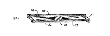
図1には、本発明の第1実施形態に係る支持集成体が示される。この実施形態は、好適にはステンレス鋼製の下支承座12を有する。
Configuration of First Embodiment FIG. 1 shows a support assembly according to a first embodiment of the present invention. This embodiment preferably has a
上支承座10もまたステンレス鋼製である。その面は実質的に平坦である。
The
支承座10、12は横断面が任意の通常的な幾何学形状とされ得る。一好適実施形態において、それらは横断面が円形である。 The bearing seats 10, 12 can be any conventional geometric shape in cross section. In one preferred embodiment, they are circular in cross section.
上支承座10および下支承座12の外周縁を、好適には加硫ゴム製のスリーブ18が囲繞する。
A
各支承座間には、摺動負荷担持部材20が在る。好適実施形態において、この摺動部材20はPTFE製の円筒体である。それは、上支承座10および下支承座12の双方に対して水平に移動し得る。There is a sliding
この実施形態では、一対の加硫ゴム製ダイヤフラム16、22が在り、各ダイヤフラムは、摺動部材20の直径よりも僅かに小さな直径の中央孔を有し、該中央孔を通して摺動部材20が緊密嵌装式に嵌合される。ダイヤフラム16、22の周縁部は夫々、ゴム製スリーブ18により支承座10、12の外周縁における凹所に保持される。In this embodiment, there is a pair of vulcanized
しかしダイヤフラムの外周縁は、金属リングもしくは当業者に知られている他の手段により所定位置に挟持され得る。However, the outer periphery of the diaphragm can be held in place by a metal ring or other means known to those skilled in the art.
図1および図1aに示す実施形態において、弾性的なセルフセンタリング力は、スリーブ18およびダイヤフラム16、22の組み合わせにより提供される。但しセルフセンタリングは、スリーブのみまたは二つのダイヤフラムのみによっても達成され得る。In the embodiment shown in FIGS. 1 and 1a, the elastic self-centering force is provided by the combination of the
スリーブ18は、該スリーブのゴムに埋設された強化材料製の環状補強リングを包含し得る。該リングは、更に大きな変位を更に等しく分散させることで、該変位の間においてスリーブを安定化させる役割を果たす。The
第2実施形態の構成
図2には、第2実施形態が示される。この実施形態において、摺動部材は、好適にはステンレス鋼製の中央薄寸部26を有する環状体24である。図4に詳細に示される如く、薄寸部26の上下に夫々画成された各凹所31内には、層状構成が在る。これは、環状体24の内側で薄寸部26に固着されたゴム層28から成る。ゴム層28に対しては、下面に凹所を備えて好適にはステンレス鋼から成る第2層30が固着される。下支承座接触表面は、ディスク状PTFEインサート32である。薄寸部26の上側には、同一の層状構造が配備される。従って上支承座10および下支承座12の夫々の面に接触する図2の実施形態における摺動部材の負荷担持表面は、各々がPTFE製である。
Configuration of the second embodiment
FIG. 2 shows a second embodiment. In this embodiment, the sliding member is an
また、図2の集成体の摺動部材から外方に突出するディスク34のような剛性部材も配備される。ディスク34の外周縁は上支承座10および下支承座12の外周縁を越えて外方に延在する。ゴム製スリーブ18は、ディスク34の周縁部まで及ぶと共に上支承座10および下支承座12の周縁部の回りに延在する。
Also provided is a rigid member such as a
第3実施形態の構成
図3に示す実施形態は、ディスク34の外周縁が上支承座10および下支承座12の外周縁に対して実質的に垂直整列して位置することを除き、図2の実施形態と実質的に同一である。これは、支承座10、12の周縁部を越えて周縁方向に延在するという図2の実施形態におけるディスク34と対照的である。
Configuration of the third embodiment
The embodiment shown in FIG. 3 is substantially the same as the embodiment of FIG. 2 except that the outer peripheral edge of the
ディスク34は、スリーブ18と摺動部材との間の堅固な接続部の役割を果たす。本発明は、他の機械的な均等物を企図する。中実のディスク34の代わりに、有孔ディスクが使用され得る。環状体24から外方に延在するスポークも利用し得る。
The
ディスク34が摺動部材に対して取付けられるのではなくスリーブ18の内側面に対して取付けられ得ることも等しく企図される。It is equally contemplated that the
斯かる実施形態では、有孔ディスク、または、内側および外側の環状リムを備えた複数本のスポークもまた、同一目的で採用され得る。In such embodiments, a perforated disc or multiple spokes with inner and outer annular rims may also be employed for the same purpose.
第4実施形態の構成
図5に示す実施形態は、図1に示す実施形態と同様の構成である。但し、上支承座38の負荷担持表面は球状であり、下支承座44の負荷担持表面も同様である。摺動部材42は、上下支承座38および44の内側面に対応する形状を有する半球状の負荷担持端面43を有する。
Configuration of the fourth embodiment
The embodiment shown in FIG. 5 has the same configuration as the embodiment shown in FIG. However, and load carrying surface of the
図5に示すダイヤフラム16、22ならびにスリーブ18は、図1に関して記述された対応ダイヤフラムおよびスリーブと同一の材料および構成である。
第5実施形態の構成
図6および図7に示す実施形態において、支持装置は、所定構造が着座する上側プレート60と、基盤(foundation)もしくは更なる構造上に着座し得る下側プレート62とを有する。プレート60、62の内面61および63はステンレス鋼により被覆される。
Configuration of the fifth embodiment
In the embodiment shown in FIGS. 6 and 7 , the support device has an
摺動部材64は、図2から図4に示す環状体と類似した、対向する一対の環状体半体70から成る。先の構成と同様に、各環状体半体における凹所内には、外方に向けて順次に3つの層が挿入される。最内側層72はゴム製である。次の層74は鋼鉄であり、かつ、外側面76はPTFE製である。
The sliding
この支持装置に対するセルフセンタリングは、図1におけるダイヤフラム16、22と殆ど同一の様式にて摺動部材64上に嵌装された上側ダイヤフラム66および下側ダイヤフラム68により提供される。
The self-centering against the supporting device is provided by the
上側ダイヤフラム66の外周縁82は、リム80上に嵌装される。図6に示すように、ダイヤフラム縁部82をリム80に対し、かつ、リム80を上側プレート60に対して固着する一群の4本のボルト78が配備される。同様に、一群の4本のボルト78は、下側ダイヤフラム縁部84をリム86に対し、かつ、リム86を下側プレート62に対して固着する。
An outer
所定構造を上側プレート60に対して固着すると共に下側プレート62を基盤または更なる構造に対して固着するために、プレート60、62における孔を貫通して(不図示の)ボルトがナット88、89内へと螺着され得る。
In order to secure the predetermined structure to the
第1実施形態の作用
図1における実施形態は、図1aにおいて作動状態で示される。地震などの外部力は、下支承座12を図示された位置へと移動させている。上支承座10と下支承座12との間の相対的な水平移動は、摺動部材20の上側表面と上支承座10の内側面との間の摩擦、及び、摺動部材20の下側表面と下支承座12の内側面との間の摩擦により制動される。
Operation of the First Embodiment The embodiment in FIG. 1 is shown in the activated state in FIG. 1a. An external force such as an earthquake moves the
スリーブ18が支持集成体の右側および左側の両方で延伸されていることが理解される。弾性スリーブ18および一対のダイヤフラム16、22の両方からの弾性的なセルフセンタリング力は、摺動部材20ならびに支承座10、12を図1に示すような中心位置へと付勢する。図1aにおいて、ダイヤフラム22の左側は弛緩しており、右側は延伸されており、ダイヤフラム16の左側は延伸されており、右側は弛緩している。
It will be appreciated that the
上下支承座間の相対移動が摺動部材20と上支承座10及び下支承座12との間の摩擦により制動される一方、スリーブ18およびダイヤフラム16、22の双方は摺動部材20および上支承座10を図1に示す中心位置へと付勢する。While the relative movement between the upper and lower bearing seats is braked by the friction between the sliding
図1に示す実施形態は、二つのダイヤフラム16、22およびスリーブ18の双方を有するが、本発明の有効範囲内である他の実施形態は、二つのダイヤフラム16、22のみを有する集成体および弾性スリーブ18のみを有する別の集成体を包含し得る。
While the embodiment shown in FIG. 1 has both two
第2および第3実施形態の作用
図3aを参照すると、地震の力は下支承座12を右側へと変位させている。摺動部材24の双方の負荷担持面と支承座10、12の夫々の負荷担持面との間の摩擦力は、各支承座間の相対移動を制動する。弾性スリーブ18は、上下支承座およびディスク34の双方を中心位置へと付勢する。
Operation of the second and third embodiments
Referring to FIG. 3a , the seismic force displaces the
第4実施形態の作用
図5に示す実施形態において各支承座の湾曲表面は、ダイヤフラム16、22ならびにスリーブ18により提供された弾性的なセルフセンタリングに対し、付加的で受動的な調心力を付加する。
Operation of the fourth embodiment
In the embodiment shown in FIG. 5 , the curved surface of each bearing seat adds an additional passive alignment force to the elastic self-centering provided by the
第5実施形態の作用
図6および図7に示す実施形態は、図1および図1aに示す第1実施形態の様式で動作する。
Operation of the fifth embodiment
The embodiment shown in FIGS. 6 and 7 operates in the manner of the first embodiment shown in FIGS. 1 and 1a .
利点
地震用の摺動式支持装置の弾性的なセルフセンタリングにより提供されるひとつの利点は、それによれば、隔離構造の周期が地震の周期を超える様に該隔離構造の周期を制御する手段が提供されることである。免震においてこれは、周期シフト(period shift)として知られている。この概念は、ジョン・ワイリー・アンド・サンズ社(John Wiley & Sons)のスキナ等(Skinner et al.)による「免震への手引き(Introduction to Seismic Isolation)」(1993)の第4〜7頁に更に十分に記述されている。
Advantages One advantage provided by the elastic self-centering of the seismic sliding support device is that it provides a means for controlling the period of the isolation structure such that the period of the isolation structure exceeds the period of the earthquake. Is to be provided. In seismic isolation, this is known as a period shift. This concept is described in pages 4-7 of "Introduction to Seismic Isolation" (1993) by John Wiley & Sons, Skinner et al. Is more fully described.
別の利点は、それが、支持集成体により占有される横断面を最小化することである。図1、図3および図5に示す支持集成体の利点は、それらが二重作用を行うことである。すなわち、頂部および底部支承座10、12は摺動部材に対して夫々が逆方向に移動することから、各支承座の摺動表面の必要サイズは1/2まで減少される。 Another advantage is that it minimizes the cross-section occupied by the support assembly. The advantage of the support assemblies shown in FIGS. 1, 3 and 5 is that they perform a double action. That is, since the top and bottom bearing seats 10 and 12 move in opposite directions with respect to the sliding member, the required size of the sliding surface of each bearing seat is reduced to ½.
支持集成体を作動させるために必要な全体的水平力F(水平)は、摩擦を克服する力F(μ)、ゴム製ダイヤフラムを変形させる力F(m)、および、ゴム製スリーブを変形させるために必要な力F(w)の合計により与えられる。ゴムを変形させる力は、概略的に弾性的な性質である。 The overall horizontal force F (horizontal) required to actuate the support assembly is the force F (μ) that overcomes friction, the force F (m) that deforms the rubber diaphragm, and the rubber sleeve. Is given by the sum of the forces F (w) required for The force that deforms the rubber is generally elastic in nature.
従って、
F(水平)=F(μ)+F(m)+F(w)
上記式中、
F(μ)=μ・F(垂直)
F(m)≒[α・E(ゴム)・t(m)]x
F(w)≒[α・E(ゴム)+β・G(ゴム)]・[A(w)/h(w)]x
であり、
上記式中、
μ=2つの摺動表面間の摩擦係数
F(垂直)=(全体質量)・g
t(m)=ダイヤフラムの厚み(図1参照)
x=底部支承座に対する頂部支承座の水平変位であり、
各支承座が調心されたときにx=0である。
α=ダイヤフラムに対する幾何学項
β=スリーブに対する幾何学項
E(ゴム)=ゴム製ダイヤフラムに対するヤング率
G(ゴム)=ゴム製スリーブの剪断弾性率
A(w)=スリーブの断面積
h(w)=スリーブの高さ(図1参照)
である。
Therefore,
F (horizontal) = F (μ) + F (m) + F (w)
In the above formula,
F (μ) = μ · F (vertical)
F (m) ≈ [α · E (rubber) · t (m)] x
F (w) ≈ [α · E (rubber) + β · G (rubber)] · [A (w) / h (w)] x
And
In the above formula,
μ = coefficient of friction between two sliding surfaces F (vertical) = (total mass) · g
t (m) = diaphragm thickness (see FIG. 1)
x = horizontal displacement of the top bearing seat relative to the bottom bearing seat,
X = 0 when each seat is aligned.
α = geometric term for the diaphragm β = geometric term for the sleeve E (rubber) = Young's modulus for the rubber diaphragm G (rubber) = shear modulus of the rubber sleeve A (w) = cross-sectional area of the sleeve h (w) = Sleeve height (see Fig. 1)
It is.
前記支持集成体の用途のひとつは、免震のための支持体としてである。免震とは、構造の揺動の固有周期が、制動の最適値と共に、地震の主要周期の値を超える値まで増大されるという技術である。これらの2つの要因の最適値に依れば、構造に対して伝達される加速度が少なくとも1/2まで減少され得る。 One use of the support assembly is as a support for seismic isolation. Seismic isolation is a technique in which the natural period of structural oscillation is increased to a value that exceeds the value of the main period of the earthquake, along with the optimum value of braking. Depending on the optimum values of these two factors, the acceleration transmitted to the structure can be reduced by at least 1/2.
本発明の支持集成体は、免震の有効性を最大化すべく設計され得るコンパクトな自己完結式ユニットである。 The support assembly of the present invention is a compact self-contained unit that can be designed to maximize the effectiveness of seismic isolation.
10 上支承座10 Upper bearing seat
12 下支承座12 Lower support seat
16 ダイヤフラム16 Diaphragm
18 スリーブ18 sleeve
20 摺動負荷担持部材(摺動部材)20 Sliding load bearing member (sliding member)
22 ダイヤフラム22 Diaphragm
34 ディスク34 discs
Claims (16)
前記摺動負荷担持部材は、前記上支承座の担持表面と摺動接触する上側表面と、前記下支承座の担持表面と摺動接触する下側表面とを有し、前記上支承座及び前記下支承座の各々に対して摺動可能とされ、
前記摺動負荷担持部材の前記上側表面と前記上支承座の担持表面との間の摩擦、及び、前記摺動負荷担持部材の前記下側表面と前記下支承座の担持表面との間の摩擦は、使用に際し、前記上支承座と前記下支承座との間の相対的な水平移動を制動する支持集成体であって、
前記支持集成体は二つのダイヤフラムを更に備え、
前記摺動負荷担持部材は、前記二つのダイヤフラムの中央箇所にもしくはその近傍に配置され、または、該中央箇所に対して結合され、
前記二つのダイヤフラムのうちの一方のダイヤフラムの周縁部は、前記上支承座及び前記下支承座のうちの一方の支承座の周縁部に結合されまたは該周縁部の近傍とされ、前記二つのダイヤフラムのうちの他方のダイヤフラムの周縁部は、前記上支承座及び前記下支承座のうちの他方の周縁部に結合されまたは該周縁部の近傍とされ、
前記二つのダイヤフラムは、前記摺動負荷担持部材を付勢することで該摺動負荷担持部材を中心位置に復帰させもしくは留まらせるように、前記摺動負荷担持部材と、前記上支承座及び前記下支承座と協働する、支持集成体。An upper bearing seat, a lower bearing seat, and a sliding load bearing member between the upper bearing seat and the lower bearing seat,
The sliding load bearing member has an upper surface that is in sliding contact with the bearing surface of the upper bearing seat, and a lower surface that is in sliding contact with the bearing surface of the lower bearing seat, the upper bearing seat and the It is slidable with respect to each of the lower support seats,
Friction between the upper surface of the sliding load bearing member and the bearing surface of the upper bearing seat, and friction between the lower surface of the sliding load bearing member and the bearing surface of the lower bearing seat Is a support assembly that, in use, brakes the relative horizontal movement between the upper and lower bearing seats,
The support assembly further comprises two diaphragms;
The sliding load carrying member is disposed at or near the center of the two diaphragms, or is coupled to the center.
A peripheral portion of one of the two diaphragms is coupled to or in the vicinity of the peripheral portion of one of the upper support seat and the lower support seat, and the two diaphragms A peripheral edge portion of the other diaphragm is coupled to or in the vicinity of the peripheral edge portion of the other of the upper support seat and the lower support seat,
The two diaphragms include the sliding load bearing member, the upper support seat, and the upper bearing seat so that the sliding load bearing member is returned to a central position or retained by urging the sliding load bearing member. A supporting assembly that works with the lower support seat.
前記上支承座の担持表面及び前記下支承座の担持表面は平坦であり、前記摺動負荷担持部材の前記上側表面及び前記下側表面は平坦である、請求項1から請求項4の何れか一つの請求項に記載の支持集成体。The sliding load bearing member has a depth and a width extending between a bearing surface of the upper bearing seat and a bearing surface of the lower bearing seat, and the width is larger than the depth,
The support surface of the upper support seat and the support surface of the lower support seat are flat, and the upper surface and the lower surface of the sliding load support member are flat. A support assembly according to one claim.
前記摺動負荷担持部材は、前記上支承座の担持表面と摺動接触する上側表面と、前記下支承座の担持表面と摺動接触する下側表面とを有し、前記上支承座及び前記下支承座の各々に対して摺動可能とされ、
前記摺動負荷担持部材の前記上側表面と前記上支承座の担持表面との間の摩擦、及び、前記摺動負荷担持部材の前記下側表面と前記下支承座の担持表面との間の摩擦は、使用に際し、前記上支承座と前記下支承座との間の相対的な水平移動を制動する支持集成体であって、
該支持集成体は更に、
前記上支承座及び前記下支承座の外周縁の全体にわたるスリーブであって、前記上支承座及び前記下支承座と協働して前記上支承座及び前記下支承座を付勢することで前記上支承座及び前記下支承座を前記摺動負荷担持部材に対する中心位置に復帰させもしくは該中心位置に留まらせるスリーブと、前記摺動負荷担持部材から外周方向に延在することで前記スリーブと協働して前記摺動負荷担持部材を前記上支承座と前記下支承座との間で中心合わせする剛性部材とを備える弾性的なセルフセンタリング手段、
を具備する支持集成体。An upper bearing seat, a lower bearing seat, and a sliding load bearing member between the upper bearing seat and the lower bearing seat,
The sliding load bearing member has an upper surface that is in sliding contact with the bearing surface of the upper bearing seat, and a lower surface that is in sliding contact with the bearing surface of the lower bearing seat, the upper bearing seat and the It is slidable with respect to each of the lower support seats,
Friction between the upper surface of the sliding load bearing member and the bearing surface of the upper bearing seat, and friction between the lower surface of the sliding load bearing member and the bearing surface of the lower bearing seat Is a support assembly that, in use, brakes the relative horizontal movement between the upper and lower bearing seats,
The support assembly further includes
A sleeve covering the entire outer peripheral edge of the upper and lower bearing seats, and by urging the upper and lower bearing seats in cooperation with the upper and lower bearing seats. A sleeve for returning the upper support seat and the lower support seat to a central position with respect to the sliding load carrying member or staying at the central position, and extending in an outer peripheral direction from the sliding load carrying member to cooperate with the sleeve. Elastic self-centering means comprising a rigid member that acts to center the sliding load bearing member between the upper and lower bearing seats;
A support assembly comprising:
前記上支承座の担持表面及び前記下支承座の担持表面は平坦であり、前記摺動負荷担持部材の前記上側表面及び前記下側表面は平坦である、請求項7から請求項10及び請求項12の何れか一つの請求項に記載の支持集成体。The sliding load bearing member has a depth and a width extending between a bearing surface of the upper bearing seat and a bearing surface of the lower bearing seat, and the width is larger than the depth,
The bearing surface of the upper bearing seat and the bearing surface of the lower bearing seat are flat, and the upper surface and the lower surface of the sliding load bearing member are flat. 13. A support assembly according to any one of claims 12 .
Applications Claiming Priority (2)
| Application Number | Priority Date | Filing Date | Title |
|---|---|---|---|
| NZ524611A NZ524611A (en) | 2003-03-07 | 2003-03-07 | Bearing assembly with sliding member between upper and lower bearing seats with elastic self-centering sleeve around seats |
| PCT/NZ2004/000045 WO2004079113A1 (en) | 2003-03-07 | 2004-03-05 | A self-centring sliding bearing |
Publications (3)
| Publication Number | Publication Date |
|---|---|
| JP2006519969A JP2006519969A (en) | 2006-08-31 |
| JP2006519969A5 JP2006519969A5 (en) | 2006-12-28 |
| JP4105744B2 true JP4105744B2 (en) | 2008-06-25 |
Family
ID=32960339
Family Applications (1)
| Application Number | Title | Priority Date | Filing Date |
|---|---|---|---|
| JP2006507901A Expired - Fee Related JP4105744B2 (en) | 2003-03-07 | 2004-03-05 | Supporting assembly |
Country Status (7)
| Country | Link |
|---|---|
| US (1) | US7547142B2 (en) |
| EP (1) | EP1604074B1 (en) |
| JP (1) | JP4105744B2 (en) |
| KR (1) | KR101065878B1 (en) |
| CN (2) | CN101319518A (en) |
| NZ (1) | NZ524611A (en) |
| WO (1) | WO2004079113A1 (en) |
Families Citing this family (22)
| Publication number | Priority date | Publication date | Assignee | Title |
|---|---|---|---|---|
| US20070151173A1 (en) * | 2005-12-30 | 2007-07-05 | Boake Paugh | Method of constructing structures with seismically-isolated base |
| GR1006394B (en) * | 2008-06-27 | 2009-05-13 | Method for elastic foundation of constructions | |
| US20110027100A1 (en) * | 2009-07-30 | 2011-02-03 | Daniel Francis Cummane | Mobile wind power station |
| US8342752B2 (en) * | 2009-09-25 | 2013-01-01 | Worksafe Technologies | Isolation bearing restraint devices |
| CN101775842B (en) * | 2009-10-23 | 2012-03-07 | 上海路博橡胶减振器技术有限公司 | Three-dimensional shock absorbing support |
| JP5740133B2 (en) * | 2010-02-16 | 2015-06-24 | 大倉 憲峰 | Fastener |
| WO2011109021A1 (en) * | 2010-03-04 | 2011-09-09 | Worksafe Technologies | Composite isolation bearing |
| TW201138682A (en) * | 2010-05-14 | 2011-11-16 | Univ Nat Taiwan Science Tech | Seat |
| IT1404858B1 (en) * | 2011-02-21 | 2013-12-09 | Milano Politecnico | ANTI-SEISMIC SUPPORT. |
| US8402702B1 (en) | 2011-04-01 | 2013-03-26 | Roberto Villaverde | Aseismic sliding isolation system using hydromagnetic bearings |
| US9121421B2 (en) * | 2011-11-23 | 2015-09-01 | Elekta Ab (Publ) | Interface and support mechanism |
| JP5521096B1 (en) * | 2013-07-25 | 2014-06-11 | 新日鉄住金エンジニアリング株式会社 | Sliding seismic isolation device |
| WO2015069120A1 (en) | 2013-11-08 | 2015-05-14 | Iso Systems Limited | A resilient bearing |
| US20180334825A1 (en) * | 2015-06-10 | 2018-11-22 | The Regents Of Teh University Of California | Architected material design for seismic isolation |
| DE102015221864A1 (en) * | 2015-11-06 | 2017-05-11 | Maurer Söhne Engineering GmbH & Co. KG | Structural bearings |
| WO2018048298A1 (en) * | 2016-09-08 | 2018-03-15 | Or Tan Teng | Seismic isolation device |
| JP2018054109A (en) * | 2016-09-30 | 2018-04-05 | 昭和電線ケーブルシステム株式会社 | Recovering rubber and its fixing structure |
| JP6836481B2 (en) * | 2017-08-28 | 2021-03-03 | オイレス工業株式会社 | Sliding pendulum type seismic isolation device |
| CN109736468A (en) * | 2019-03-22 | 2019-05-10 | 哈尔滨工业大学 | A kind of assembled buttress-support integration earthquake isolating equipment |
| US11193294B2 (en) * | 2020-04-06 | 2021-12-07 | National Cheng-Kung University | Double variable sliding isolator |
| US11255099B2 (en) * | 2020-04-20 | 2022-02-22 | Saeed Towfighi | Steel plate damper for structures subject to dynamic loading |
| US20230104946A1 (en) * | 2021-10-01 | 2023-04-06 | Saeed Towfighi | Steel plate damper for structures |
Family Cites Families (40)
| Publication number | Priority date | Publication date | Assignee | Title |
|---|---|---|---|---|
| US2014643A (en) * | 1933-08-31 | 1935-09-17 | Jacob F J Bakker | Balance block for buildings |
| DE1759108C3 (en) * | 1968-03-30 | 1978-04-20 | Nell, Hans Alfred, Dipl.-Ing., 5602 Langenberg | Strip-shaped bearing |
| DE2829309B2 (en) * | 1978-07-04 | 1980-08-07 | Glacier Gmbh Deva Werke | Method for lining the concave upper side of the lower plate of a tilting movement of a bridge superstructure or the like. enabling warehouse and lined with this method |
| CA1186359A (en) | 1981-06-09 | 1985-04-30 | Edward R. Fyfe | Bearings for structures |
| JPS58124843A (en) * | 1982-01-20 | 1983-07-25 | Mitsubishi Steel Mfg Co Ltd | Vibration-insulating device |
| JPS6070276A (en) | 1983-09-28 | 1985-04-22 | 秋元 将男 | Earthquake-proof support apparatus |
| JPS61106864A (en) * | 1984-10-30 | 1986-05-24 | 株式会社東芝 | Earthquake-proof floor apparatus |
| US4644714A (en) * | 1985-12-02 | 1987-02-24 | Earthquake Protection Systems, Inc. | Earthquake protective column support |
| JP2524360B2 (en) * | 1987-07-14 | 1996-08-14 | トキコ株式会社 | Seismic isolation device |
| JPS6418810U (en) | 1987-07-23 | 1989-01-30 | ||
| JPS6443643A (en) * | 1987-08-12 | 1989-02-15 | Tokico Ltd | Earthquake damping apparatus |
| JP2629011B2 (en) * | 1987-12-01 | 1997-07-09 | エヌティエヌ株式会社 | Seismic isolation sliding device |
| DE69119797D1 (en) * | 1990-01-20 | 1996-07-04 | Sumitomo Rubber Ind | Anti-vibration device |
| US5261200A (en) * | 1990-01-20 | 1993-11-16 | Sumitomo Gomu Kogyo Kabushiki Kaisha | Vibration-proofing device |
| GR1001450B (en) | 1992-12-24 | 1993-12-30 | Ioannis Logiadis | Bound vibration antiseismic joint for the secure seismic insulation of the constructions. |
| IT1271242B (en) * | 1994-10-04 | 1997-05-27 | Fip Ind | SUPPORTING DEVICE WITH SPHERICAL SHELL, ANTI-SCALOTING PARTICULARLY DESIGNED TO BIND BRIDGES, VIADUCTS, BUILDINGS AND SIMILAR |
| DE29503801U1 (en) | 1995-02-24 | 1995-04-27 | Haidermetall Eduard Haider KG, 95704 Pullenreuth | Swinging standing floor |
| JPH0914345A (en) * | 1995-06-28 | 1997-01-14 | Nitta Ind Corp | Base isolation device for light load |
| JP2660825B2 (en) * | 1995-07-13 | 1997-10-08 | 株式会社カイモン | Elastic bearing device for cross girder bearing and method of installing the same |
| JPH1073145A (en) * | 1996-06-14 | 1998-03-17 | Mitsubishi Steel Mfg Co Ltd | Base isolation sliding support for structural body |
| JPH1038022A (en) * | 1996-07-22 | 1998-02-13 | Tomiharu Shindo | Base isolation device |
| US6021992A (en) * | 1997-06-23 | 2000-02-08 | Taichung Machinery Works Co., Ltd. | Passive vibration isolating system |
| JP3939435B2 (en) * | 1997-06-25 | 2007-07-04 | 株式会社奥村組 | Seismic isolation device |
| US6249925B1 (en) | 1997-06-30 | 2001-06-26 | Japan Highway Public Corporation | Bridge of shock-absorbing construction |
| JP2002061414A (en) * | 1998-01-06 | 2002-02-28 | Jiro Kitamura | Base isolation device, sliding bearing, and base isolation structure |
| JPH11350783A (en) * | 1998-06-10 | 1999-12-21 | Bridgestone Corp | Vibration-isolating system |
| JP2000064657A (en) * | 1998-08-25 | 2000-02-29 | Hazama Gumi Ltd | Three-dimensional base isolation device and structure |
| JP2001074094A (en) * | 1999-09-07 | 2001-03-23 | Bando Chem Ind Ltd | Base isolation device |
| WO2000037823A1 (en) | 1998-12-18 | 2000-06-29 | Bando Chemical Industries, Ltd. | Vibration isolating apparatus |
| JP2000257670A (en) * | 1999-03-08 | 2000-09-19 | Bando Chem Ind Ltd | Base isolation device |
| JP2000283230A (en) * | 1999-03-31 | 2000-10-13 | Kumagai Gumi Co Ltd | Base isolation device and base isolation structure |
| US6289640B1 (en) * | 1999-07-09 | 2001-09-18 | Nippon Pillar Packing Co., Ltd. | Seismic isolation sliding support bearing system |
| JP2002021927A (en) * | 2000-07-03 | 2002-01-23 | Ohbayashi Corp | Base isolation device |
| JP3685706B2 (en) * | 2000-10-06 | 2005-08-24 | 大同メタル工業株式会社 | Seismic isolation device |
| JP2002276194A (en) * | 2001-03-19 | 2002-09-25 | Sugimoto Kenchiku Kenkyusho:Kk | Seismic isolator |
| JP3722713B2 (en) * | 2001-04-02 | 2005-11-30 | 大同メタル工業株式会社 | Seismic isolation device |
| WO2002084030A1 (en) * | 2001-04-12 | 2002-10-24 | Fine Co., Ltd. | Combination-type earthquake-proof apparatus |
| JP2002364704A (en) * | 2001-06-08 | 2002-12-18 | Safety Techno:Kk | Sliding bearing type base isolation device |
| DE10145857B4 (en) | 2001-08-06 | 2004-11-18 | Roger Hertzfeldt | Bearing construction for the damped transmission of shock and / or vibration forces, especially for structures that are exposed to a seismic load |
| US6971795B2 (en) * | 2001-11-26 | 2005-12-06 | Lee George C | Seismic isolation bearing |
-
2003
- 2003-03-07 NZ NZ524611A patent/NZ524611A/en not_active IP Right Cessation
-
2004
- 2004-03-05 JP JP2006507901A patent/JP4105744B2/en not_active Expired - Fee Related
- 2004-03-05 CN CNA2008101360441A patent/CN101319518A/en active Pending
- 2004-03-05 EP EP04717908A patent/EP1604074B1/en not_active Expired - Lifetime
- 2004-03-05 CN CNB2004800119265A patent/CN100416005C/en not_active Expired - Fee Related
- 2004-03-05 KR KR1020057016671A patent/KR101065878B1/en not_active IP Right Cessation
- 2004-03-05 US US10/548,193 patent/US7547142B2/en not_active Expired - Fee Related
- 2004-03-05 WO PCT/NZ2004/000045 patent/WO2004079113A1/en active Application Filing
Also Published As
| Publication number | Publication date |
|---|---|
| CN1784529A (en) | 2006-06-07 |
| WO2004079113A1 (en) | 2004-09-16 |
| CN100416005C (en) | 2008-09-03 |
| US7547142B2 (en) | 2009-06-16 |
| KR101065878B1 (en) | 2011-09-19 |
| NZ524611A (en) | 2005-09-30 |
| US20060272226A1 (en) | 2006-12-07 |
| JP2006519969A (en) | 2006-08-31 |
| CN101319518A (en) | 2008-12-10 |
| EP1604074B1 (en) | 2012-08-22 |
| EP1604074A1 (en) | 2005-12-14 |
| EP1604074A4 (en) | 2009-02-11 |
| KR20050109976A (en) | 2005-11-22 |
Similar Documents
| Publication | Publication Date | Title |
|---|---|---|
| JP4105744B2 (en) | Supporting assembly | |
| JPH04131539A (en) | Earthquake bearing | |
| JP2002266933A (en) | Cone inside ball accommodation type earthquake isolation bearing | |
| JP5803930B2 (en) | Vehicle air spring and cart using the same | |
| US20170114846A1 (en) | Brake disk | |
| US6890137B2 (en) | Ambulance stretcher support to reduce patient trauma | |
| JP2008302902A (en) | Air spring for railway vehicle | |
| EP2860422A1 (en) | Brake device | |
| JP3937042B2 (en) | Strut mount | |
| JP5297602B2 (en) | Railway vehicle suspension system | |
| US10883559B2 (en) | Damping valve for a vibration damper | |
| JP6118686B2 (en) | Seismic isolation device and load transmission plate | |
| US10781877B2 (en) | Hub for mounting a brake disc to a vehicle axis | |
| JP3737439B2 (en) | Anti-vibration support | |
| JP2000074138A (en) | Slide type base isolation device for lightweight structure | |
| JPS6047417B2 (en) | Internal seismic support system for buildings | |
| JP2008082353A (en) | Laminated support | |
| US6622841B2 (en) | Clutch disk | |
| JP4118387B2 (en) | Bearing device | |
| JPH1144125A (en) | Base isolation device | |
| JP2009287390A (en) | Pile head junction structure | |
| US4358004A (en) | Load-taking apparatus for a disc pack | |
| WO2006028391A1 (en) | Self centring sliding bearing | |
| JPH09242375A (en) | Vibration isolating device for light load | |
| JP4881519B2 (en) | Seismic isolation device trigger device |
Legal Events
| Date | Code | Title | Description |
|---|---|---|---|
| A521 | Written amendment |
Free format text: JAPANESE INTERMEDIATE CODE: A523 Effective date: 20061110 |
|
| A621 | Written request for application examination |
Free format text: JAPANESE INTERMEDIATE CODE: A621 Effective date: 20061110 |
|
| A871 | Explanation of circumstances concerning accelerated examination |
Free format text: JAPANESE INTERMEDIATE CODE: A871 Effective date: 20061110 |
|
| A131 | Notification of reasons for refusal |
Free format text: JAPANESE INTERMEDIATE CODE: A131 Effective date: 20061219 |
|
| A521 | Written amendment |
Free format text: JAPANESE INTERMEDIATE CODE: A523 Effective date: 20070319 |
|
| A975 | Report on accelerated examination |
Free format text: JAPANESE INTERMEDIATE CODE: A971005 Effective date: 20070419 |
|
| A711 | Notification of change in applicant |
Free format text: JAPANESE INTERMEDIATE CODE: A711 Effective date: 20070406 |
|
| A131 | Notification of reasons for refusal |
Free format text: JAPANESE INTERMEDIATE CODE: A131 Effective date: 20070612 |
|
| A521 | Written amendment |
Free format text: JAPANESE INTERMEDIATE CODE: A523 Effective date: 20070912 |
|
| A131 | Notification of reasons for refusal |
Free format text: JAPANESE INTERMEDIATE CODE: A131 Effective date: 20071030 |
|
| A521 | Written amendment |
Free format text: JAPANESE INTERMEDIATE CODE: A523 Effective date: 20080129 |
|
| TRDD | Decision of grant or rejection written | ||
| A01 | Written decision to grant a patent or to grant a registration (utility model) |
Free format text: JAPANESE INTERMEDIATE CODE: A01 Effective date: 20080226 |
|
| A61 | First payment of annual fees (during grant procedure) |
Free format text: JAPANESE INTERMEDIATE CODE: A61 Effective date: 20080327 |
|
| R150 | Certificate of patent or registration of utility model |
Free format text: JAPANESE INTERMEDIATE CODE: R150 |
|
| FPAY | Renewal fee payment (event date is renewal date of database) |
Free format text: PAYMENT UNTIL: 20110404 Year of fee payment: 3 |
|
| FPAY | Renewal fee payment (event date is renewal date of database) |
Free format text: PAYMENT UNTIL: 20120404 Year of fee payment: 4 |
|
| FPAY | Renewal fee payment (event date is renewal date of database) |
Free format text: PAYMENT UNTIL: 20130404 Year of fee payment: 5 |
|
| FPAY | Renewal fee payment (event date is renewal date of database) |
Free format text: PAYMENT UNTIL: 20140404 Year of fee payment: 6 |
|
| R250 | Receipt of annual fees |
Free format text: JAPANESE INTERMEDIATE CODE: R250 |
|
| R250 | Receipt of annual fees |
Free format text: JAPANESE INTERMEDIATE CODE: R250 |
|
| LAPS | Cancellation because of no payment of annual fees |