JP4104277B2 - Inkjet recording apparatus and image forming apparatus - Google Patents
Inkjet recording apparatus and image forming apparatus Download PDFInfo
- Publication number
- JP4104277B2 JP4104277B2 JP2000212094A JP2000212094A JP4104277B2 JP 4104277 B2 JP4104277 B2 JP 4104277B2 JP 2000212094 A JP2000212094 A JP 2000212094A JP 2000212094 A JP2000212094 A JP 2000212094A JP 4104277 B2 JP4104277 B2 JP 4104277B2
- Authority
- JP
- Japan
- Prior art keywords
- electrode
- diaphragm
- ink
- nozzle
- ink droplets
- Prior art date
- Legal status (The legal status is an assumption and is not a legal conclusion. Google has not performed a legal analysis and makes no representation as to the accuracy of the status listed.)
- Expired - Fee Related
Links
Images


Landscapes
- Particle Formation And Scattering Control In Inkjet Printers (AREA)
Description
【0001】
【産業上の利用分野】
本発明はインクジェット記録装置及び画像形成装置に関し、特に静電型ヘッドを搭載したインクジェット記録装置及び画像形成装置に関する。
【0002】
【従来の技術】
プリンタ、ファクシミリ、複写装置、プロッタ等の画像記録装置(画像形成装置)として用いるインクジェット記録装置として、インク滴を吐出するノズルと、このノズルが連通するインク流路(吐出室、圧力室、加圧液室、液室等とも称される。)と、このインク流路の壁面をなす振動板と、この振動板に対向する電極とを有し、振動板を静電力で変形変位させてノズルからインク滴を吐出させる静電型インクジェットヘッドを搭載したものが知られている。
【0003】
ところで、このようなインクジェットヘッドは、ノズルからインク滴を吐出するため、インク粘度が環境によって変化すると、安定したインク滴吐出特性(滴速度Vj、滴体積Mj、滴噴射方向の曲がり)が得られなくなり、画像品質が劣化する。また、環境変化だけでなく、非印字時にインク粘度が高くなると、ノズルの目詰まりが生じて、著しく画像が劣化する。特に、画質を向上するために、吐出インク滴を微小化しなければならないことから、ノズルの小径化が進んでおり、一層ノズルの目詰まりが生じ易くなっている。さらに、ノズルの目詰まりを起こさないまでも、非印字時間の長さによって、次に印字信号が入力された際のインク滴吐出特性に差が生じて画質が低下する。
【0004】
そこで、例えば再公表特許WO97/32728号公報に記載されているように、単一周期の基準信号に同期して、インク滴吐出が可能な振幅の第1の電気パルスと、この第1の電気パルスの振幅より小さく、ノズル内のインクをノズル内で流動させる第2の電圧パルスのいずれか一方を、ノズルの目詰まり防止の回復処理動作時と印刷行程中に各圧力発生手段に印加するインクジェット記録装置が知られている。
【0005】
【発明が解決しようとする課題】
しかしながら、上述した第1の電気パルスと第2の電気パルスを同じタイミングで選択的に各圧力発生手段に印加するインクジェット記録装置にあっては、インクジェットヘッドのエネルギー発生手段をなす共通電極(振動板)と個別電極のうち、共通電極に与える電圧を切り換えるスイッチ手段と、個別電極の電圧を切り換えるスイッチ手段とを有し、かつ個別電極には2つの水準の電圧を切り換えて与えるようにしなければならず、コストが高くなる。
【0006】
本発明は上記の課題に鑑みてなされたものであり、吐出する液体の粘度上昇やノズルの目詰まりを低コストで低減したインクジェット記録装置及び画像形成装置を提供することを目的とする。
【0007】
【課題を解決するための手段】
上記の課題を解決するため、本発明に係るインクジェット記録装置は、振動板が電極に当接する変位を行なうことによりノズルからインク滴を吐出させ、振動板が電極に当接しない変位を行なうことにより駆動時にインク滴を吐出させないノズルのメニスカスを1回以上振動させる手段を備えているものである。
本発明に係る画像形成装置は、振動板が電極に当接する変位を行なうことによりノズルから滴を吐出させ、振動板が電極に当接しない変位を行なうことにより駆動時に滴を吐出させないノズルのメニスカスを1回以上振動させる手段を備えているものである。
【0008】
本発明に係るインクジェット記録装置は、振動板が電極に当接する変位を行なうことによりノズルからインク滴を吐出させ、駆動時にインク滴を吐出させないノズルに対して、振動板が電極に当接しない変位を行なうことによりインク滴が吐出しない駆動波形を1回以上与えてメニスカスを振動させる手段を備えているものである。
【0009】
本発明に係るインクジェット記録装置は、振動板が電極に当接する変位を行なうことによりノズルからインク滴を吐出させ、インクジェットヘッドが非印字領域にあるときに、振動板が電極に当接しない変位を行なうことによりインク滴が吐出しない駆動波形を1回以上与えてメニスカスを振動させる手段を備えているものである。
【0010】
ここで、インク滴が吐出しない駆動波形はインク滴を吐出させる駆動波形よりもパルス幅が狭いパルスとすることができる。また、インク滴が吐出しない駆動波形はインク滴が吐出する駆動波形よりもパルスの立ち下がり時間が長いパルスとすることもできる。また、振動板と電極間のギャップ長が振動板の変位により1/3の長さに達する前に振動板を変位させるパルス電圧を立ち下げて振動板が電極に当接しない変位を行なう構成とできる。
【0011】
【発明の実施の形態】
以下、本発明の実施の形態を添付図面を参照して説明する。図1は本発明に係る画像形成装置としてのインクジェット記録装置の機構部の概略斜視説明図、図2は同機構部の側面説明図である。
【0012】
このインクジェット記録装置は、記録装置本体1の内部に主走査方向に移動可能なキャリッジ、キャリッジに搭載したインクジェットヘッドからなる記録ヘッド、記録ヘッドへのインクを供給するインクカートリッジ等で構成される印字機構部2等を収納し、装置本体1の下方部には前方側から多数枚の用紙3を積載可能な給紙カセット(或いは給紙トレイでもよい。)4を抜き差し自在に装着することができ、また、用紙3を手差しで給紙するための手差しトレイ5を開倒することができ、給紙カセット4或いは手差しトレイ5から給送される用紙3を取り込み、印字機構部2によって所要の画像を記録した後、後面側に装着された排紙トレイ6に排紙する。
【0013】
印字機構部2は、図示しない左右の側板に横架したガイド部材である主ガイドロッド11と従ガイドロッド12とでキャリッジ13を主走査方向(図2で紙面垂直方向)に摺動自在に保持し、このキャリッジ13にはイエロー(Y)、シアン(C)、マゼンタ(M)、ブラック(Bk)の各色のインク滴を吐出するインクジェットヘッドからなる記録ヘッド14をインク滴吐出方向を下方に向けて装着し、キャリッジ13の上側には記録ヘッド14に各色のインクを供給するための各インクタンク(インクカートリッジ)15を交換可能に装着している。
【0014】
ここで、キャリッジ13は後方側(用紙搬送方向下流側)を主ガイドロッド11に摺動自在に嵌装し、前方側(用紙搬送方向上流側)を従ガイドロッド12に摺動自在に載置している。そして、このキャリッジ13を主走査方向に移動走査するため、主走査モータ17で回転駆動される駆動プーリ18と従動プーリ19との間にタイミングベルト20を張装し、このタイミングベルト20をキャリッジ13に固定している。
【0015】
また、記録ヘッドとしてここでは各色の記録ヘッド14を用いているが、各色のインク滴を吐出するノズルを有する1個のヘッドでもよい。さらに、記録ヘッド14として用いるインクジェットヘッドは、後述するように、インク流路壁面を形成する振動板とこれに対向する電極との間の静電力で振動板を変位させてインクを加圧する静電型のものを用いている。
【0016】
一方、給紙カセット4にセットした用紙3を記録ヘッド14の下方側に搬送するために、給紙カセット4から用紙3を分離給送する給紙ローラ21及びフリクションパッド22と、用紙3を案内するガイド部材23と、給紙された用紙3を反転させて搬送する搬送ローラ24と、この搬送ローラ24の周面に押し付けられる搬送コロ25及び搬送ローラ24からの用紙3の送り出し角度を規定する先端コロ26とを設けている。搬送ローラ24は副走査モータ27によってギヤ列を介して回転駆動される。
【0017】
そして、キャリッジ13の主走査方向の移動範囲に対応して搬送ローラ24から送り出された用紙3を記録ヘッド14の下方側で案内する用紙ガイド部材である印写受け部材29を設けている。この印写受け部材29の用紙搬送方向下流側には、用紙3を排紙方向へ送り出すために回転駆動される搬送コロ31、拍車32を設け、さらに用紙3を排紙トレイ6に送り出す排紙ローラ33及び拍車34と、排紙経路を形成するガイド部材35,36とを配設している。
【0018】
また、キャリッジ13の移動方向右端側には記録ヘッド14の信頼性を維持、回復するための信頼性維持回復機構(以下「サブシステム」という。)37を配置している。キャリッジ13は印字待機中にはこのサブシステム37側に移動されてキャッピング手段などで記録ヘッド14をキャッピングされる。キャリッジ13がこのサブシステム37側に位置するときがインクジェットヘッド(ヘッド14)が非印字領域に位置するときである。
【0019】
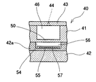
次に、このインクジェット記録装置の記録ヘッド14を構成するインクジェットヘッドについて図3乃至5を参照して説明する。なお、図3は記録ヘッド14の分解斜視説明図、図4は同記録ヘッド14のノズル配列方向と直交する方向の断面説明図、図5は同記録ヘッド14のノズル配列方向の要部拡大断面図である。
【0020】
インクジェットヘッド40は、単結晶シリコン基板、SOI基板などのシリコン基板等を用いた流路基板41と、この流路基板41の下側に設けたシリコン基板、パイレックスガラス基板、セラミックス基板等を用いた電極基板42と、流路基板41の上側に設けたノズル板43とを備え、複数のインク滴を吐出するノズル44、各ノズル44が連通するインク流路である液室46、各液室46にインク供給路を兼ねた流体抵抗部47を介して連通する共通液室流路48などを形成している。
【0021】
流路基板41には液室46及びこの液室46の壁面である底部をなす振動板50(第1の電極となる。)を形成する凹部を形成し、ノズル板43には流体抵抗部47を形成する溝を形成し、また流路基板41と電極基板42には共通液室流路48を形成する貫通部を形成している。
【0022】
ここで、流路基板41は、例えば単結晶シリコン基板を用いた場合、予め振動板厚さにボロンを注入してエッチングストップ層となる高濃度ボロン層を形成し、電極基板42と接合した後、液室46となる凹部をKOH水溶液などのエッチング液を用いて異方性エッチングすることにより、このとき高濃度ボロン層がエッチングストップ層となって振動板50が高精度に形成される。
【0023】
なお、振動板50に別途電極膜を形成してもよいが、上述したように不純物の拡散などによって振動板が電極を兼ねるようにしている。また、振動板50の電極基板42側の面に絶縁膜を形成することもできる。この絶縁膜としてはSiO2等の酸化膜系絶縁膜、Si3N4等の窒化膜系絶縁膜などを用いることができる。絶縁膜の成膜は、振動板表面を熱酸化して酸化膜を形成したり、成膜手法を用いたりすることができる。
【0024】
また、電極基板42には酸化膜層42aを形成し、この酸化膜層42aの部分に凹部54を形成して、この凹部54底面に振動板50に対向する電極15(第2の電極となる。)を設け、振動板50と電極55との間にギャップ56を形成し、これらの振動板50と電極55とによってアクチュエータ部を構成している。なお、電極55表面にはSiO2膜などの酸化膜系絶縁膜、Si3N4膜などの窒化膜系絶縁膜からなる電極保護膜57を成膜しているが、電極表面55に電極保護膜57を形成しないで、振動板50側に絶縁膜を形成することもできる。
【0025】
この電極基板42として単結晶シリコン基板を用いる場合には通常のシリコンウエハーを用いることができる。その厚さはシリコンウエハーの直径で異なるが、直径4インチのシリコンウエハーであれば厚さが500μm程度、直径6インチのシリコンウエハーであれば厚さは600μm程度であることが多い。シリコンウエハー以外の材料を選択する場合には、流路基板のシリコンと熱膨張係数の差が小さい方が振動板と接合する場合に信頼性を向上できる。
【0026】
これらの流路基板41と電極基板42との接合は、接着剤による接合も可能であるが、より信頼性の高い物理的な接合、例えば電極基板42がシリコンで形成される場合、酸化膜を介した直接接合法を用いることができる。この直接接合は1000℃程度の高温化で実施する。また、電極基板42がガラスの場合、陽極接合を行うことができる。電極基板42をシリコンで形成して、陽極接合を行う場合には、電極基板42と流路基板41との間にパイレックスガラスを成膜し、この膜を介して陽極接合を行うこともできる。さらに、流路基板41と電極基板42にシリコン基板を使用して金等のバインダーを接合面に介在させた共晶接合で接合することもできる。
【0027】
また、電極基板42の電極55としては、通常半導体素子の形成プロセスで一般的に用いられるAl、Cr、Ni等の金属材料や、Ti、TiN、W等の高融点金属、または不純物により低抵抗化した多結晶シリコン材料などを用いることができる。電極基板42をシリコンウエハで形成する場合には、電極基板42と電極55との間には絶縁層(上述した酸化膜層42a)を形成する必要がある。電極基板42にガラス等の絶縁性材料を用いる場合には電極55との間に絶縁層を形成する必要はない。
【0028】
また、電極基板42にシリコン基板を用いる場合、電極55としては、不純物拡散領域を用いることができる。この場合、拡散に用いる不純物は基板シリコンの導電型と反対の導電型を示す不純物を用い、拡散領域周辺にpn接合を形成し、電極55と電極基板42とを電気的に絶縁する。
【0029】
ノズル板43は多数のノズル44を二列配置して形成したものであり、吐出面には撥水処理を施している。ここでは、このノズル板43はNi電鋳工法で製作しているが、この他、例えば樹脂と金属層の複層構造のものなども用いることができる。このノズル板43は流路基板41に接着剤にて接合している。
【0030】
このインクジェットヘッド40ではノズル44を二列配置し、この各ノズル44に対応して液室46、振動板50、電極55なども二列配置し、各ノズル列の中央部に共通液室流路48を配置して、左右の液室46にインクを供給する構成を採用している。これにより、簡単なヘッド構成で多数のノズルを有するマルチノズルヘッドを構成することができる。
【0031】
そして、インクジェットヘッド40の電極55は外部に延設して接続部(電極パッド部)55aとし、これにヘッド駆動回路であるドライバIC60を搭載したFPCケーブル61を異方性導電膜などを介して接続している。このとき、電極基板42とノズル板43との間は図4に示すようにエポキシ樹脂等の接着剤を用いたギャップ封止剤62にて気密封止している。
【0032】
さらに、インクジェットヘッド40全体をフレーム部材65上に接着剤で接合している。このフレーム部材65にはインクジェットヘッド40の共通液室流路48に外部からインクを供給するためのインク供給穴66を形成しており、またFPCケーブル61等はフレーム部材65に形成した穴部67に収納される。
【0033】
このフレーム部材65とノズル板43との間は図4に示すようにエポキシ樹脂等の接着剤を用いたギャップ封止剤68にて封止し、撥水性を有するノズル板43表面のインクが電極基板42やFPCケーブル61等に回り込むことを防止している。
【0034】
そして、この記録ヘッド14のフレーム部材65にはインクカートリッジ15とのジョイント部材70が連結されて、フィルタ71を介してインクカートリッジ15からインク供給穴66を通じて共通液室流路48にインクが供給される。
【0035】
このインクジェットヘッド40においては、振動板50を共通電極とし、電極55を個別電極として(逆の構成とすることもできる。)、振動板50と電極55との間に駆動電圧(駆動波形)を印加することによって、振動板50と電極55との間に発生する静電力によって振動板50が電極55側に変形変位し、この状態から振動板50と電極55間の電荷を放電させることによって振動板50が復帰変形して、液室46の内容積(体積)/圧力が変化することによって、ノズル44からインク滴が吐出される。
【0036】
すなわち、個別電極とする電極55にパルス電圧を印加すると、共通電極となる振動板50との間に電位差が生じて、個別電極55と振動板50の間に静電力が生じる。この結果、振動板50は印加した電圧の大きさに応じて電極55側に変形変位する。その後、印加したパルス電圧を立ち下げることで、振動板50が復元して、その復元力により液室46内の圧力が高くなり、ノズル44からインク滴が吐出される。この場合、振動板50を電極55(実際には絶縁保護膜57表面)に当接させる位置まで変位させる方式を当接駆動方式、振動板50を電極55に当接させない位置まで変位させる方式を非当接駆動方式と称する。
【0037】
ここで、当接駆動方式で駆動する場合、駆動波形の電圧印加により変位した振動板50は、振動板50と電極55間のギャップ長の1/3の位置に達すると、振動板50に働く機械的な力と静電力とのバランスにより、電極55に当接する。その後、印加した駆動波形を立ち下げることで、振動板50の変位が復元し、その復元力により前述したようにインク滴が吐出する。
【0038】
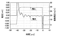
ここで、図6に示すように、パルス状の駆動波形を印加した場合、振動板50が電極55に当接した後は、駆動波形のパルス幅を長くすると、電流波形は振動しながら減衰していく形になる(以下、「残留振動」と称する)。
【0039】
この残留振動とインク滴吐出特性の関係について見ると、図7に示すように、図6の残留振動波形で見られる残留振動のいずれのタイミングでパルスを切る(ここでは、駆動波形を立ち下げる)かによって、インク滴吐出特性(吐出滴速度Vj、吐出滴質量Mj)が変動することが分かる。
【0040】
この図7に示す例の場合には、駆動波形のパルス幅PWを4μsecより狭く設定した場合、吐出滴速度Vj及び吐出滴体積Mjが第1のピークになるパルス幅と次の第2のピークになるパルス幅の間のパルス幅に設定した場合では、いずれもインク滴が吐出されないことが分かる。
【0041】
つまり、パルス電圧の印加により振動板50が変位し始めて、ギャップ長の1/3の位置に達するまでの時間内にパルスを立ち下げるような、短い時間の(パルス幅PWの狭い)パルスや、圧力振動が相殺されるようなタイミングに当たるパルス幅PWでは、振動板50はインク滴が吐出するほどの復元力にならないため、インク滴は吐出せずにノズル44内のメニスカスが振動するのみとなる。
【0042】
また、パルス立ち下げ時間を長くとり、振動板50の変位の復元をゆっくり行うことでも、インク滴を吐出させずにノズル44内のメニスカスのみを振動させることが可能である。これらの特性を積極的に利用することで、インクの増粘によるノズルの目詰まりを低減することができる。
【0043】
次に、このインクジェット記録装置の制御部の概要について図8を参照して説明する。
この制御部は、この記録装置全体の制御を司るマイクロコンピュータ(以下、「CPU」と称する。)80と、所要の固定情報を格納したROM81と、ワーキングメモリ等として使用するRAM82と、ホスト側から転送される画像データを処理したデータを格納する画像メモリ83と、パラレル入出力(PIO)ポート84と、入力バッファ85と、パラレル入出力(PIO)ポート86と、波形生成回路87と、ヘッド駆動回路88及びドライバ89等を備えている。
【0044】
ここで、PIOポート84にはホスト側から画像データなどの各種情報、図示しない操作パネルからの信頼性回復指示情報等の各種指示情報、用紙の始端、終端を検知する紙有無センサからの検知信号、キャリッジ13のホームポジション(基準位置)を検知するホームポジションセンサ等の各種センサからの信号等が入力され、またこのPIOポート84を介してホスト側や操作パネル側に対して所要の情報が送出される。
【0045】
また、波形生成回路87は、インクジェットヘッド40の振動板50と電極55との間にインク滴を吐出させるエネルギーを発生する、つまり、振動板50をインク滴が吐出するだけの変位量、タイミングで電極55側に変位させ、復元させる第1駆動波形と、インク滴を吐出させずにメニスカスを振動させるエネルギーを発生する、つまり、振動板50をインク滴が吐出せずにメニスカスが振動するにとまる変位量、タイミングで電極55側に変位させ、復元させる第2駆動波形とを、時系列で生成出力する。
【0046】
ヘッド駆動回路88は、PIOポート86を介して与えられる各種データ及び信号に基づいて、記録ヘッド14の各ノズル44に対応するエネルギー発生手段(振動板50と電極55)に対して第1駆動波形又は第2駆動波形を印加する。さらに、ドライバ89は、PIOポート86を介して与えられる駆動データに応じて主走査モータ17及び副走査モータ27を各々駆動制御することで、キャリッジ13を主走査方向に移動走査し、搬送ローラ24を回転させて用紙3を所定量搬送させる。
【0047】
次に、この制御部におけるヘッド駆動制御に係わる部分について図9を参照して説明する。
このヘッド駆動制御部は、前述したCPU80、ROM81、RAM82及び周辺回路等を含む主制御部91と、波形生成回路87と、アンプ92と、駆動回路(ドライバIC)93等とを備えている。
【0048】
主制御部91は、波形生成回路87に対して第1駆動波形と第2駆動波形を生成するためのデータを与え、ドライバIC93に対して印字信号(シリアルデータである)SD、シフトクロックCLK、ラッチ信号LATなどを与える。
【0049】
波形生成回路87は、前述したようにインクジェットヘッド40のアクチュエータ部に対してノズル44からインク滴を吐出させるエネルギーを発生させる第1駆動波形と、ノズル44からインク滴を吐出しないでメニスカス面を振動させる第2駆動波形とを時系列で発生する。この波形生成回路87からの出力を駆動波形(駆動電圧)Pvとする。この波形生成回路87にはD/A変換器を用いて主制御部91から与えられる電圧データをD/A変換することによりパルス幅の異なる駆動波形を時系列で生成出力するようにしている。
【0050】
すなわち、ここでは、駆動波形Pvは、図10(a)に示すように、パルス幅PW1の第1駆動波形である第1駆動パルスDpと、第1駆動パルスDpよりパルス幅の狭いパルス幅PW2の第2駆動波形である2個の第2駆動パルスBpとを、ヘッドの1駆動周期で繰り返し時系列で発生する。したがって、インク滴を吐出させないノズル(駆動しないチャンネル)に第2駆動パルスBpを与えることにより、メニスカスを1回以上(ここでは2回)振動させることができる。
【0051】
ドライバIC93は、時系列で入力される駆動波形Pvから第1駆動パルスDp又は第2駆動パルスBpを印字信号に応じて選択して、記録ヘッド14を構成するインクジェットヘッド40の各個別電極55に与える。このドライバIC93は、主制御部91からのシリアルクロックCLK及び印字信号であるシリアルデータSDを入力するシフトレジスタ95と、シフトレジスタ95のレジスト値を主制御部91からのラッチ信号LATでラッチするラッチ回路96と、ラッチ回路96の出力値をレベル変化するレベル変換回路97と、このレベル変換回路97でオン/オフが制御されるアナログスイッチアレイ98とからなる。アナログスイッチアレイ98は、インクジェットヘッド40のm個(ノズル数をm個とする。)の個別電極55に接続したアナログスイッチAS1〜ASmからなる。なお、インクジェットヘッド40の共通電極となる振動板50は接地している。
【0052】
そして、このシフトレジスタ回路95にシフトクロックCLKに応じて印字信号(シリアルデータ)SDを取込み、ラッチ回路96でラッチ信号LATによってシフトレジスタ回路95に取り込んだ印字信号SDをラッチしてレベル変換回路98に入力する。このレベル変換回路98は、データの内容に応じて各アクチュエータ部の個別電極55に接続しているアナログスイッチASm(m=1〜m)をオン/オフする。
【0053】
このアナログスイッチASm(m=1〜m)には波形生成回路87からアンプ(AMP)92を介して駆動波形Pvを与えているので、アナログスイッチASm(m=1〜m)がオンしたときに駆動波形Pv(第1駆動パルスDp又は第2駆動パルスBp)が個別電極55に与えられる。
【0054】
次に、このように構成したインクジェット記録装置における本発明の第1実施形態について図10をも参照して説明する。
まず、上述したように、波形生成回路87からは図10(a)に示すように1駆動周期内でパルス幅PW1の第1駆動パルスDp及びパルス幅PW2の2個の第2駆動パルスBpとが時系列で生成出力され、これがドライバIC93のアナログスイッチAS1〜ASmに与えられている。
【0055】
そこで、駆動時に主制御部91から印字信号SDを与えることによって、例えば同図(b)に示すように、インク滴を吐出するビット(チャンネル)に対応するドライバIC93のアナログスイッチASn(n=1〜mのいずれか)がオンし、アナログスイッチASnがオンしている間に入力される第1駆動パルスDp又は第2駆動パルスBpが同図(c)に示すようにインクジェットヘッド40の個別電極55に与えられる。
【0056】
この図10(c)は駆動時における1つのノズル44に対応する個別電極55に印加されるパルスを示しているものであり、このノズル44は、図示している最初の駆動周期では印字(駆動)であるので、第1駆動パルスDpが与えられてインク滴が吐出し、次の駆動周期では印字しない(インク滴を吐出させない)のでアナログスイッチASnをオフにして第2駆動パルスBpを与えてノズルのメニスカスを振動させる。
【0057】
なお、具体的には、液室長約1000μm、振動板厚さ約2μm、ノズル径約20μmとしたインクジェットヘッドを製作し、前述した図7のパルス幅特性を参考して、インク滴吐出に使う第1駆動パルスDpのパルス幅をPW1を6μm、メニスカス振動に使う第2駆動パルスBpのパルス幅PW2を2μs、電圧は両パルスとも30Vにして実験したところ、第1駆動パルスDpの印加頻度にかかわらず差異のないインク滴吐出特性が得られ、インクの増粘による滴吐出特性の変化が低減することを確認できた。
【0058】
このように駆動時にインク滴を吐出させないノズルのメニスカスを振動させる手段を備えているので、例えば、インク吐出頻度が少ないノズルでも、インクの増粘による滴吐出特性の変化が低減し、安定したインク滴吐出特性を得られる。これにより、印字開始直後のドットの乱れが解消され、ドット位置精度の高い良好な印字画像が得られる。この場合、インク滴を吐出させない駆動波形を印加してメニスカスを振動させることで、簡単な構成で、低コストで、インクの増粘によるインク滴吐出特性の低下を抑えることができる。
【0059】
次に、本発明の第2実施形態について図11を参照して説明する。
この実施形態においては、上記第1実施形態が駆動時に非吐出ノズル(インク滴を吐出させないノズル)のメニスカスを振動させる例であったのに対し、キャリッジ13をサブシステム37側に移動させたとき、すなわち、ヘッド14が非印字領域にあるときには、すべてのノズル44のメニスカスを振動させる処理を行うようにしたものである。
【0060】
すなわち、ヘッド14を非印字位置である印字待機位置(サブシステム37による信頼性維持回復位置)にしたときに、タイマT1をセット・スタートして、タイマT1がタイムアップしたときには信頼性維持回復処理を行う。この信頼性維持回復処理では、公知のようにヘッド14をキャップ手段でキャッピングした状態で吸引手段を駆動してヘッド14のノズル44からインクを吸引排出することによってノズル44の増粘したインクを排出する処理をしたり、或いは、全ノズル44を駆動してインク滴を吐出することによってノズル44の増粘したインクを排出する処理をする。
【0061】
そして、信頼性維持回復動作後タイマT1、T2をセット・スタートし、印字指令があるか否かを判別し、印字指令がなければ、タイマT1がタイムアップしたか否かを判別する処理に戻る。
【0062】
ここで、タイマT1がタイムアップしていなければ、タイマT2がタイムアップしているか否かを判別し、タイマT2がタイムアップしたときには、前記第1実施形態で説明したと同様なヘッド駆動制御によって、時系列で生成出力される第1駆動パルスDpと第2駆動パルスBpのうちの第2駆動パルスBpのみを選択してヘッド14に与えることにより、信頼性維持回復動作の間にメニスカス振動のみを行って、ノズル44のインクの増粘を抑制する処理を行う。
【0063】
このように、信頼性維持回復動作の一環として所定時間毎にインク滴を吐出しないでメニスカス振動のみを行う維持回復処理を行うことによって、インクの増粘を抑えることができるので、インク滴の排出を伴なう維持回復処理の回数(クリーニング動作回数)を減らすことができて、無駄なインク消費を低減することができる。
【0064】
そして、このメニスカス振動のためのヘッドの駆動を時系列で生成出力される第1駆動波形と第2駆動波形のうちの第2駆動波形のみを選択してヘッドに与えることにより、構成が簡単になり、低コスト化を図れる。さらに、前記実施形態のように印字動作中(駆動時)にもメニスカス振動を行う構成と組み合わせることができ、これによりインクの増粘を低コストで抑制することができる。
【0065】
図11に戻って、印字指令が与えられたときには、印字動作に移行する直前にメニスカス振動を行ってノズル44内のインク粘度を回復した後、印字処理に移行する。これにより、安定した印字を迅速に開始することができる。
【0066】
次に、本発明の第3実施形態について図12を参照して説明する。
この実施形態においては、上記第2実施形態ではヘッドの非印字領域におけるメニスカス振動を信頼性維持回復動作の一環として行っていたのに対し、信頼性維持回復動作とは関係なく、1走査終了でヘッド14をサブシステム37側の非印字領域に移動して、すべてのノズル44に対してメニスカス振動(1回又は複数回)を行った後、次の走査のためにヘッド14を印字領域に移動させる処理を行う。なお、メニスカス振動を行うノズルを全てのノズルとしないで、複数の領域(ノズル群)に分割して各走査毎に順次ノズル群のノズルのメニスカス振動を行うようにすることもできる。
【0067】
このようにしても、インクの増粘によるインク滴吐出特性の低下を防止でき、信頼性維持回復動作の回数が少なくなって無駄なインク消費を低減することができる。
【0068】
なお、上記各実施形態においては、時系列で出力される第1駆動波形と第2駆動波形とを用いているが、これに限るものではなく、例えば図13に示すように、三端子スイッチ100のアレイをドライバICに用いて、三端子スイッチ100の一方に第1駆動パルスDpを、他方に第2駆動パルスBpを与えて、三端子スイッチ100を印字信号に応じて切り換えてヘッド14に印加する駆動波形を選択することもできる。
【0069】
また、上記各実施形態では、図10(a)に示すようにメニスカス振動用に駆動パルスDpよりもパルス幅PWが狭いパルス駆動パルスBpを2個を用いているが、図14(a)に示す第1駆動パルスDpに対してパルス幅PWの狭い同図(b)に示す1個の第2駆動パルスBpを用いることもできる。このように第2駆動パルスBpは第1駆動パルスDpよりもパルス幅PWの狭いパルスとすることにより、パルス生成を簡略な回路構成で実現することができる。
【0070】
また、第2駆動パルスBpとしては、同図(d)に示すように、図7に示すパルス幅特性の谷の部分(振動板55を引っ張った際の残留圧力振動と振動板55の復元力が打ち消すように重ね合わされたタイミング)のパルス幅PW、すなわち、滴吐出体積Mj及び滴吐出速度Vjが第1のピークになるパルス幅と次のピークになるパルス幅の間のパルス幅PWに設定したものを用いることもできる。さらに、同図(c)に示すように、第1駆動パルスDpよりも立ち下がりを緩やかにした(立ち下がり時間が長い)パルスを用いることもできる。
【0071】
なお、上記各実施形態においては、振動板をインク滴を吐出しない程度の変位量、タイミングで変形させる駆動波形を用いてメニスカス振動を行うようにしたが、この他、別途、加圧室内のインクを振動させる振動手段を設けてメニスカス振動を行うようにすることもできる。また、上記実施形態ではインクジェットヘッドは振動板と液室とを流路基板として同一部材から形成しているが、振動板と液室を形成している部材とを別部材で形成して接合することもできる。
【0072】
また、インクジェット記録装置に搭載するインクジェットヘッドは、流路基板中に形成したノズル、液室、流体抵抗部、共通流路液室の形状、配置、形成方法は適切に変更することができる。例えば、上記の実施形態においては、ノズルは振動板の変位方向にインク滴が吐出するように形成したサイドシュータ方式のインクジェットヘッドであるが、ノズルを振動板の変位方向と交差する方向にインク滴が吐出するように形成したエッジシュータ方式のインクジェットヘッドでもよい。
【0073】
【発明の効果】
以上説明したように、本発明に係るインクジェット記録装置によれば、振動板が電極に当接する変位を行なうことによりノズルからインク滴を吐出させ、振動板が電極に当接しない変位を行なうことにより駆動時にインク滴を吐出させないノズルのメニスカスを1回以上振動させる手段を備えているので、低コストで、インク吐出の頻度が少ないノズルにおいてもインクの増粘によるインク滴吐出特性の変動を抑えることができ、印字画像の乱れが予防できて、より高品質の画像を得ることをできる。
本発明に係る画像形成装置によれば、振動板が電極に当接する変位を行なうことによりノズルから滴を吐出させ、振動板が電極に当接しない変位を行なうことにより駆動時に滴を吐出させないノズルのメニスカスを1回以上振動させる手段を備えているので、低コストで、滴吐出の頻度が少ないノズルにおいても増粘による滴吐出特性の変動を抑えることができ、印字画像の乱れが予防できて、より高品質の画像を得ることをできる。
【0074】
本発明に係るインクジェット記録装置によれば、振動板が電極に当接する変位を行なうことによりノズルからインク滴を吐出させ、駆動時にインク滴を吐出させないノズルに対して、振動板が電極に当接しない変位を行なうことによりインク滴が吐出しない駆動波形を1回以上与えてメニスカスを振動させる手段を備えているので、低コストで、インク吐出の頻度が少ないノズルにおいてもインクの増粘によるインク滴吐出特性の変動を抑えることができ、印字画像の乱れが予防できて、より高品質の画像を得ることをできる。
【0075】
本発明に係るインクジェット記録装置によれば、振動板が電極に当接する変位を行なうことによりノズルからインク滴を吐出させ、インクジェットヘッドが非印字領域にあるとき、振動板が電極に当接しない変位を行なうことによりにインク滴が吐出しない駆動波形を1回以上与えてメニスカスを振動させる手段を備えているので、低コストで、印字開始直後のドットの乱れを解消することができて、ドット位置精度の高い良好な印字画像を得ることができ、また、画像の乱れが低減されて信頼性維持回復の動作回数が減り、無駄なインク消費を減らすことができるので画質の向上とコストダウンを共に図ることができる。
【0076】
この場合、インク滴を吐出させない駆動波形はインク滴を吐出させる駆動波形よりもパルス幅が狭いパルスとし、或いは、立ち下がり時間が長い波形とすることで、二種類の駆動波形を容易に生成することができる。
【図面の簡単な説明】
【図1】本発明に係るインクジェット記録装置の機構部の概略斜視説明図
【図2】同機構部の側面説明図
【図3】同記録装置のヘッドの分解斜視説明図
【図4】同ヘッドの振動板長手方向の断面説明図
【図5】同ヘッドの振動板短手方向の要部拡大断面説明図
【図6】同ヘッドの駆動波形のパルス幅、電流波形及びパルス電圧の関係を説明する説明図
【図7】同ヘッドの駆動波形のパルス幅と吐出滴速度及び吐出滴体積の関係を説明する説明図
【図8】同記録装置の制御部の一例を示すブロック図
【図9】同制御部の内のヘッド駆動制御部の一例を示すブロック図
【図10】同記録装置における本発明の第1実施形態の説明に供する説明図
【図11】本発明の第2実施形態の説明に供するフロー図
【図12】本発明の第3実施形態の説明に供するフロー図
【図13】同記録装置におけるヘッド駆動制御部の他の例の説明に供する説明図
【図14】インク滴を吐出させない駆動波形の他の異なる例の説明に供する説明図
【符号の説明】
13…キャリッジ、14…記録ヘッド、24…搬送ローラ、33…排紙ローラ、40…インクジェットヘッド、41…流路基板、42…電極基板、43…ノズル板、44…ノズル、46…液室、47…流体抵抗部、48…共通流路液室、50…振動板、55…電極、56…ギャップ、87…波形生成回路、91…主制御部、60、93…ドライバIC、95…シフトレジスタ、96…ラッチ回路、97…レベル変換回路、98…アナログスイッチアレイ。[0001]
[Industrial application fields]
The present invention relates to an ink jet recording apparatus.And image forming apparatusIn particular,Electrostatic headInkjet recording device equipped withAnd image forming apparatusAbout.
[0002]
[Prior art]
As an ink jet recording apparatus used as an image recording apparatus (image forming apparatus) such as a printer, a facsimile, a copying apparatus, or a plotter, a nozzle that ejects ink droplets and an ink flow path (discharging chamber, pressure chamber, pressurizing) that communicate with the nozzle A liquid chamber, a liquid chamber, etc.), a diaphragm that forms the wall surface of the ink flow path, and an electrode that faces the diaphragm, and the diaphragm is deformed and displaced by electrostatic force from the nozzle. A device equipped with an electrostatic ink jet head for discharging ink droplets is known.
[0003]
By the way, since such an ink jet head ejects ink droplets from nozzles, stable ink droplet ejection characteristics (drop velocity Vj, droplet volume Mj, bend in the droplet ejection direction) can be obtained when the ink viscosity changes depending on the environment. The image quality deteriorates. In addition to environmental changes, if the ink viscosity increases during non-printing, nozzle clogging occurs and the image deteriorates significantly. In particular, in order to improve the image quality, it is necessary to make the ejected ink droplets minute, so that the diameter of the nozzle is reduced and the nozzle is more easily clogged. Furthermore, even if the nozzles are not clogged, the image quality deteriorates due to a difference in the ink droplet ejection characteristics when the next print signal is input due to the length of the non-print time.
[0004]
Therefore, for example, as described in the
[0005]
[Problems to be solved by the invention]
However, in the ink jet recording apparatus that selectively applies the first electric pulse and the second electric pulse to each pressure generating means at the same timing, the common electrode (vibrating plate) that forms the energy generating means of the ink jet head is used. ) And switching means for switching the voltage applied to the common electrode, and switching means for switching the voltage of the individual electrode, and two levels of voltage should be switched and applied to the individual electrode. The cost is high.
[0006]
The present invention has been made in view of the above problems,Of liquid to be dischargedInkjet recording device with reduced viscosity and nozzle clogging at low costAnd image forming apparatusThe purpose is to provide.
[0007]
[Means for Solving the Problems]
In order to solve the above problems, an ink jet recording apparatus according to the present invention includes:Displacement in which the diaphragm abuts on the electrode causes ink droplets to be ejected from the nozzles, and displacement that the diaphragm does not abut on the electrodeProvided with means to vibrate the meniscus of the nozzle that does not eject ink droplets at least once during drivingingIs.
An image forming apparatus according to the present invention discharges droplets from a nozzle by performing a displacement in which a diaphragm abuts against an electrode, and disposes a meniscus of a nozzle that does not eject a droplet during driving by performing a displacement in which the diaphragm does not abut an electrode. Is provided with a means for vibrating at least once.
[0008]
The inkjet recording apparatus according to the present invention isThe ink droplets are ejected from the nozzles by moving the diaphragm so that it abuts the electrodes,For nozzles that do not eject ink droplets when drivenBy displacing the diaphragm so that it does not contact the electrodeMeans are provided that vibrate the meniscus by giving a drive waveform that does not eject ink droplets one or more times.
[0009]
The inkjet recording apparatus according to the present invention isThe ink droplets are ejected from the nozzles by moving the diaphragm so that it abuts the electrodes,When the inkjet head is in the non-printing areaBy displacing the diaphragm so that it does not contact the electrodeMeans are provided that vibrate the meniscus by giving a drive waveform that does not eject ink droplets one or more times.
[0010]
Here, the drive waveform that does not eject ink droplets can be a pulse having a narrower pulse width than the drive waveform that ejects ink droplets. Further, the drive waveform in which the ink droplet is not ejected can be a pulse having a longer pulse fall time than the drive waveform in which the ink droplet is ejected.Further, the configuration is such that the pulse voltage for displacing the diaphragm is lowered before the gap length between the diaphragm and the electrode reaches 1 / due to the displacement of the diaphragm so that the diaphragm does not contact the electrode. it can.
[0011]
DETAILED DESCRIPTION OF THE INVENTION
Embodiments of the present invention will be described below with reference to the accompanying drawings. FIG. 1 relates to the present invention.As an image forming deviceFIG. 2 is a side perspective view of the mechanism portion of the ink jet recording apparatus. FIG.
[0012]
The ink jet recording apparatus includes a carriage that is movable in the main scanning direction inside the recording apparatus
[0013]
The
[0014]
Here, the
[0015]
Further, although the
[0016]
On the other hand, in order to convey the paper 3 set in the
[0017]
A
[0018]
Further, a reliability maintenance / recovery mechanism (hereinafter referred to as “subsystem”) 37 for maintaining and recovering the reliability of the
[0019]
Next, an ink jet head constituting the
[0020]
The
[0021]
The
[0022]
Here, for example, when a single crystal silicon substrate is used as the
[0023]
Although an electrode film may be separately formed on the
[0024]
Further, an
[0025]
When a single crystal silicon substrate is used as the
[0026]
The
[0027]
Further, the
[0028]
Further, when a silicon substrate is used for the
[0029]
The
[0030]
In this
[0031]
The
[0032]
Further, the
[0033]
The gap between the
[0034]
A
[0035]
In the
[0036]
That is, when a pulse voltage is applied to the
[0037]
Here, in the case of driving by the contact driving method, when the
[0038]
Here, as shown in FIG. 6, when a pulsed drive waveform is applied, after the
[0039]
Looking at the relationship between the residual vibration and the ink droplet ejection characteristics, as shown in FIG. 7, the pulse is cut at any timing of the residual vibration seen in the residual vibration waveform of FIG. 6 (here, the drive waveform is lowered). It can be seen that the ink droplet ejection characteristics (ejection droplet velocity Vj, ejection droplet mass Mj) vary.
[0040]
In the case of the example shown in FIG. 7, when the pulse width PW of the drive waveform is set to be narrower than 4 μsec, the pulse width at which the ejection droplet velocity Vj and the ejection droplet volume Mj become the first peak and the next second peak. It can be seen that no ink droplets are ejected when the pulse width is set between the pulse widths.
[0041]
That is, a pulse of a short time (with a narrow pulse width PW) such that the
[0042]
Also, it is possible to vibrate only the meniscus in the
[0043]
Next, an outline of the control unit of the ink jet recording apparatus will be described with reference to FIG.
The control unit includes a microcomputer (hereinafter referred to as “CPU”) 80 that controls the entire recording apparatus, a
[0044]
Here, the
[0045]
The
[0046]
Based on various data and signals given through the
[0047]
Next, a portion related to head drive control in this control unit will be described with reference to FIG.
The head drive control unit includes a
[0048]
The
[0049]
The
[0050]
That is, here, as shown in FIG. 10A, the drive waveform Pv includes a first drive pulse Dp that is a first drive waveform having a pulse width PW1, and a pulse width PW2 that is narrower than the first drive pulse Dp. Two second drive pulses Bp, which are the second drive waveforms, are repeatedly generated in time series in one drive cycle of the head. Therefore, the meniscus can be vibrated once or more (here, twice) by giving the second drive pulse Bp to a nozzle (channel not driven) that does not eject ink droplets.
[0051]
The
[0052]
The
[0053]
Since the analog switch ASm (m = 1 to m) is supplied with the drive waveform Pv from the
[0054]
Next, a first embodiment of the present invention in the ink jet recording apparatus configured as described above will be described with reference to FIG.
First, as described above, from the
[0055]
Therefore, by supplying the print signal SD from the
[0056]
FIG. 10C shows a pulse applied to the
[0057]
Specifically, an ink jet head having a liquid chamber length of about 1000 μm, a diaphragm thickness of about 2 μm, and a nozzle diameter of about 20 μm is manufactured, and the first used for ink droplet ejection with reference to the pulse width characteristic of FIG. An experiment was conducted with the pulse width of one drive pulse Dp being 6 μm PW1, the pulse width PW2 of the second drive pulse Bp used for meniscus vibration being 2 μs, and the voltage being 30 V for both pulses, depending on the frequency of application of the first drive pulse Dp. Thus, it was confirmed that the ink droplet ejection characteristics having no difference were obtained, and the change in the droplet ejection characteristics due to the thickening of the ink was reduced.
[0058]
In this way, since it has means to vibrate the meniscus of the nozzle that does not eject ink droplets during driving, for example, even with a nozzle with low ink ejection frequency, the change in droplet ejection characteristics due to ink thickening is reduced, and stable ink Drop ejection characteristics can be obtained. Thereby, the dot disturbance immediately after the start of printing is eliminated, and a good print image with high dot position accuracy can be obtained. In this case, by applying a drive waveform that does not eject ink droplets to vibrate the meniscus, it is possible to suppress a drop in ink droplet ejection characteristics due to ink thickening at a low cost with a simple configuration.
[0059]
Next, a second embodiment of the present invention will be described with reference to FIG.
In this embodiment, the first embodiment is an example in which the meniscus of a non-ejection nozzle (a nozzle that does not eject ink droplets) is vibrated during driving, whereas the
[0060]
That is, when the
[0061]
Then, after the reliability maintaining and recovering operation, the timers T1 and T2 are set and started to determine whether or not there is a print command. If there is no print command, the process returns to the process of determining whether or not the timer T1 has timed up. .
[0062]
Here, if the timer T1 has not expired, it is determined whether or not the timer T2 has expired. When the timer T2 expires, the same head drive control as described in the first embodiment is performed. By selecting only the second drive pulse Bp from the first drive pulse Dp and the second drive pulse Bp generated and output in time series and giving them to the
[0063]
As described above, the ink viscosity can be suppressed by performing the maintenance recovery process in which only the meniscus vibration is performed without ejecting the ink droplets every predetermined time as part of the reliability maintenance recovery operation. This can reduce the number of maintenance and recovery processes involving cleaning (the number of cleaning operations), thereby reducing wasted ink consumption.
[0064]
Then, by selecting only the second drive waveform of the first drive waveform and the second drive waveform generated and output in time series for driving the head for the meniscus vibration, the configuration can be simplified. Therefore, cost reduction can be achieved. Furthermore, it can be combined with a configuration in which meniscus vibration is performed even during a printing operation (during driving) as in the above-described embodiment, and thereby, thickening of ink can be suppressed at a low cost.
[0065]
Returning to FIG. 11, when a print command is given, meniscus vibration is performed immediately before shifting to the printing operation to recover the ink viscosity in the
[0066]
Next, a third embodiment of the present invention will be described with reference to FIG.
In this embodiment, the meniscus vibration in the non-printing area of the head is performed as part of the reliability maintenance / recovery operation in the second embodiment, whereas one scan is completed regardless of the reliability maintenance / recovery operation. After moving the
[0067]
Even in this case, it is possible to prevent a drop in ink droplet ejection characteristics due to thickening of the ink, and the number of operations for maintaining and recovering reliability can be reduced, thereby reducing wasteful ink consumption.
[0068]
In each of the above embodiments, the first drive waveform and the second drive waveform output in time series are used. However, the present invention is not limited to this. For example, as shown in FIG. Is applied to the
[0069]
In each of the above embodiments, as shown in FIG. 10A, two pulse drive pulses Bp having a narrower pulse width PW than the drive pulse Dp are used for meniscus vibration. It is also possible to use one second drive pulse Bp shown in FIG. 5B having a narrow pulse width PW with respect to the first drive pulse Dp shown. As described above, the second drive pulse Bp is a pulse having a narrower pulse width PW than the first drive pulse Dp, whereby pulse generation can be realized with a simple circuit configuration.
[0070]
Further, as shown in FIG. 6D, the second drive pulse Bp includes a valley portion of the pulse width characteristic shown in FIG. 7 (residual pressure vibration when the
[0071]
In each of the above embodiments, the meniscus vibration is performed using a drive waveform that deforms the diaphragm at a displacement amount and timing that does not eject ink droplets. It is also possible to perform a meniscus vibration by providing a vibration means for vibrating the lens. In the above embodiment, the ink jet head is formed of the same member using the vibration plate and the liquid chamber as the flow path substrate. However, the vibration plate and the member forming the liquid chamber are formed of different members and joined. You can also.
[0072]
Moreover, the shape, arrangement | positioning, and formation method of the nozzle formed in the flow-path board | substrate, the liquid chamber, the fluid resistance part, and the common flow-path liquid chamber can be changed suitably for the inkjet head mounted in an inkjet recording device. For example, in the above-described embodiment, the nozzle is a side shooter type inkjet head formed so that ink droplets are ejected in the displacement direction of the vibration plate, but the ink droplets in the direction intersecting the displacement direction of the vibration plate. May be an edge shooter type inkjet head formed so as to be discharged.
[0073]
【The invention's effect】
As described above, according to the inkjet recording apparatus of the present invention,Displacement in which the diaphragm abuts on the electrode causes ink droplets to be ejected from the nozzles, and displacement that the diaphragm does not abut on the electrodeWhen drivinginkBecause it has a means to vibrate the meniscus of the nozzle that does not eject droplets one or more times, at low cost,inkEven with nozzles that discharge less frequentlyInkBy thickeninginkIt is possible to suppress fluctuations in the droplet ejection characteristics, prevent the printed image from being disturbed, and obtain a higher quality image.
According to the image forming apparatus of the present invention, the nozzle that does not discharge droplets during driving by discharging the droplets from the nozzle by performing a displacement in which the diaphragm abuts against the electrodes and performing the displacement in which the diaphragm does not contact the electrodes. Because it is equipped with a means to vibrate the meniscus at least once, it is possible to suppress fluctuations in droplet ejection characteristics due to thickening even at nozzles that are low in cost and low in frequency of droplet ejection, and can prevent disturbance of the printed image. , You can get a higher quality image.
[0074]
According to the inkjet recording apparatus of the present invention,The ink droplets are ejected from the nozzles by moving the diaphragm so that it abuts the electrodes,For nozzles that do not eject ink droplets when drivenBy displacing the diaphragm so that it does not contact the electrodeSince there is provided a means for vibrating the meniscus by giving a drive waveform that does not eject ink droplets one or more times, even at nozzles that are less expensive and less frequent ink ejection, variations in ink droplet ejection characteristics due to ink thickening are suppressed. Therefore, the disturbance of the printed image can be prevented and a higher quality image can be obtained.
[0075]
According to the inkjet recording apparatus of the present invention,The ink droplets are ejected from the nozzles by moving the diaphragm so that it abuts the electrodes,When the inkjet head is in a non-printing areaBy displacing the diaphragm so that it does not contact the electrodeSince it is equipped with a means to vibrate the meniscus by giving a drive waveform that does not eject ink droplets one or more times, it can eliminate dot disturbance immediately after the start of printing, and has good dot position accuracy. Print image can be obtained, and the disturbance of the image is reduced, the number of operations for maintaining and recovering reliability is reduced, and wasteful ink consumption can be reduced, so that both improvement in image quality and cost reduction can be achieved. .
[0076]
In this case, the drive waveform that does not eject ink droplets is a pulse with a narrower pulse width than the drive waveform that ejects ink droplets, or a waveform with a long fall time.TossThus, two types of drive waveforms can be easily generated.
[Brief description of the drawings]
FIG. 1 is a schematic perspective explanatory view of a mechanism portion of an ink jet recording apparatus according to the present invention.
FIG. 2 is an explanatory side view of the mechanism part.
FIG. 3 is an exploded perspective view of the head of the recording apparatus.
FIG. 4 is a cross-sectional explanatory view of the head in the longitudinal direction of the diaphragm.
FIG. 5 is an enlarged cross-sectional explanatory view of the main part of the head in the short direction of the diaphragm.
FIG. 6 is an explanatory diagram for explaining the relationship between the pulse width, current waveform, and pulse voltage of the drive waveform of the head.
FIG. 7 is an explanatory diagram for explaining the relationship between the pulse width of the driving waveform of the head, the ejection droplet velocity, and the ejection droplet volume.
FIG. 8 is a block diagram showing an example of a control unit of the recording apparatus
FIG. 9 is a block diagram showing an example of a head drive control unit in the control unit
FIG. 10 is an explanatory diagram for explaining the first embodiment of the present invention in the recording apparatus.
FIG. 11 is a flowchart for explaining a second embodiment of the present invention.
FIG. 12 is a flowchart for explaining a third embodiment of the present invention.
FIG. 13 is an explanatory diagram for explaining another example of a head drive control unit in the recording apparatus.
FIG. 14 is an explanatory diagram for explaining another example of a driving waveform that does not eject ink droplets.
[Explanation of symbols]
DESCRIPTION OF
Claims (8)
前記振動板が前記電極に当接する変位を行なうことにより前記ノズルからインク滴を吐出させ、
前記振動板が前記電極に当接しない変位を行なうことにより駆動時にインク滴を吐出させないノズルのメニスカスを1回以上振動させる手段を備えていることを特徴とするインクジェット記録装置。A nozzle that ejects ink droplets; an ink channel that communicates with the nozzle; a diaphragm that is provided in a part of the channel; and an electrode that faces the diaphragm; In an inkjet recording apparatus provided with an inkjet head that is deformed by and ejects ink droplets from the nozzle,
The ink droplets are ejected from the nozzles by performing a displacement in which the diaphragm abuts on the electrodes,
An ink jet recording apparatus comprising: means for vibrating the meniscus of a nozzle that does not eject ink droplets during driving by causing the vibration plate to be displaced so as not to contact the electrode .
前記振動板が前記電極に当接する変位を行なうことにより前記ノズルからインク滴を吐出させ、
駆動時にインク滴を吐出させないノズルに対して、前記振動板が前記電極に当接しない変位を行なうことによりインク滴が吐出しない駆動波形を1回以上与えてメニスカスを振動させる手段を備えていることを特徴とするインクジェット記録装置。A plurality of nozzles for discharging ink droplets, an ink flow path communicating with the nozzles, a vibration plate provided in a part of the flow path, and an electrode facing the vibration plate; In an inkjet recording apparatus including an inkjet head that is deformed by an electrostatic force and ejects ink droplets from the nozzle,
The ink droplets are ejected from the nozzles by performing a displacement in which the diaphragm abuts on the electrodes,
A means for vibrating the meniscus by giving a drive waveform not ejecting ink droplets one or more times by performing a displacement in which the vibration plate does not contact the electrode with respect to a nozzle that does not eject ink droplets during driving. An ink jet recording apparatus.
前記振動板が前記電極に当接する変位を行なうことにより前記ノズルからインク滴を吐出させ、
前記インクジェットヘッドが非印字領域にあるときに、前記振動板が前記電極に当接しない変位を行なうことによりインク滴が吐出しない駆動波形を1回以上与えてメニスカスを振動させる手段を備えていることを特徴とするインクジェット記録装置。A plurality of nozzles for discharging ink droplets, an ink flow path communicating with the nozzles, a vibration plate provided in a part of the flow path, and an electrode facing the vibration plate; In an inkjet recording apparatus including an inkjet head that is deformed by an electrostatic force and ejects ink droplets from the nozzle,
The ink droplets are ejected from the nozzles by performing a displacement in which the diaphragm abuts on the electrodes,
When the ink jet head is in a non-printing area, there is provided means for vibrating the meniscus by giving a driving waveform at which ink droplets are not ejected one or more times by performing a displacement in which the vibration plate does not contact the electrode . An ink jet recording apparatus.
前記振動板が前記電極に当接する変位を行なうことにより前記ノズルから滴を吐出させ、
前記振動板が前記電極に当接しない変位を行なうことにより駆動時に滴を吐出させないノズルのメニスカスを1回以上振動させる手段を備えていることを特徴とする画像形成装置。It has a nozzle that discharges droplets, a flow path that communicates with the nozzle, a vibration plate provided in a part of the flow path, and an electrode that faces the vibration plate, and the vibration plate is deformed by an electrostatic force. In an image forming apparatus including an electrostatic head that discharges droplets from the nozzle,
By causing the diaphragm to abut against the electrode, a droplet is ejected from the nozzle,
An image forming apparatus comprising: a means for vibrating the meniscus of a nozzle that does not eject droplets during driving by causing the vibration plate to be displaced so as not to contact the electrode .
Priority Applications (1)
| Application Number | Priority Date | Filing Date | Title |
|---|---|---|---|
| JP2000212094A JP4104277B2 (en) | 2000-07-13 | 2000-07-13 | Inkjet recording apparatus and image forming apparatus |
Applications Claiming Priority (1)
| Application Number | Priority Date | Filing Date | Title |
|---|---|---|---|
| JP2000212094A JP4104277B2 (en) | 2000-07-13 | 2000-07-13 | Inkjet recording apparatus and image forming apparatus |
Publications (3)
| Publication Number | Publication Date |
|---|---|
| JP2002019104A JP2002019104A (en) | 2002-01-23 |
| JP2002019104A5 JP2002019104A5 (en) | 2006-03-02 |
| JP4104277B2 true JP4104277B2 (en) | 2008-06-18 |
Family
ID=18708056
Family Applications (1)
| Application Number | Title | Priority Date | Filing Date |
|---|---|---|---|
| JP2000212094A Expired - Fee Related JP4104277B2 (en) | 2000-07-13 | 2000-07-13 | Inkjet recording apparatus and image forming apparatus |
Country Status (1)
| Country | Link |
|---|---|
| JP (1) | JP4104277B2 (en) |
Families Citing this family (4)
| Publication number | Priority date | Publication date | Assignee | Title |
|---|---|---|---|---|
| JP2006088488A (en) | 2004-09-22 | 2006-04-06 | Fuji Xerox Co Ltd | Inkjet recorder and inkjet recording method |
| JP2009166246A (en) * | 2008-01-10 | 2009-07-30 | Olympus Corp | Image recorder, control method for image recorder, and program therefor |
| JP5262476B2 (en) * | 2008-09-10 | 2013-08-14 | 富士ゼロックス株式会社 | Droplet ejection apparatus and program |
| CN115447285A (en) | 2021-06-09 | 2022-12-09 | 松下知识产权经营株式会社 | Ink ejection device |
-
2000
- 2000-07-13 JP JP2000212094A patent/JP4104277B2/en not_active Expired - Fee Related
Also Published As
| Publication number | Publication date |
|---|---|
| JP2002019104A (en) | 2002-01-23 |
Similar Documents
| Publication | Publication Date | Title |
|---|---|---|
| JP4243340B2 (en) | Inkjet recording apparatus, image forming apparatus, head drive control apparatus, head drive control method, and inkjet head | |
| JP4251912B2 (en) | Image forming apparatus | |
| JP2005014431A (en) | Image forming apparatus | |
| JP3659494B2 (en) | Liquid ejector | |
| JP4408608B2 (en) | Head drive control device and image recording device | |
| JP2002211011A (en) | Ink jet recorder and printer driver | |
| JP2004042576A (en) | Head drive controller and image recorder | |
| JP2003237066A (en) | Head driving control device and image recorder | |
| JP2005041039A (en) | Image forming device | |
| JP2014058095A (en) | Liquid discharge head, and image formation device | |
| JP4104277B2 (en) | Inkjet recording apparatus and image forming apparatus | |
| JP2004090542A (en) | Inkjet recorder | |
| JP2001179964A (en) | Drive controller for head and ink jet recorder | |
| JP4259741B2 (en) | Inkjet recording apparatus and image forming apparatus | |
| JP4342744B2 (en) | Head drive device and ink jet recording apparatus | |
| JP2002254625A (en) | Ink jet recording device | |
| JP2003011361A (en) | Head driver and ink jet recorder | |
| JP2004160903A (en) | Head driving controller and image recorder | |
| JP2001353865A (en) | Ink jet recorder | |
| JP6136006B2 (en) | Droplet ejection apparatus and image forming apparatus | |
| JP3933378B2 (en) | Inkjet head, inkjet recording apparatus, and image forming apparatus | |
| JP2002036537A (en) | Ink jet recorder | |
| JP4138420B2 (en) | Droplet ejection head, inkjet recording apparatus, image forming apparatus, and apparatus for ejecting droplets | |
| JP2002144545A (en) | Ink jet recorder | |
| JP2012011635A (en) | Method of and apparatus for driving ink jet head |
Legal Events
| Date | Code | Title | Description |
|---|---|---|---|
| A621 | Written request for application examination |
Free format text: JAPANESE INTERMEDIATE CODE: A621 Effective date: 20041125 |
|
| A521 | Written amendment |
Free format text: JAPANESE INTERMEDIATE CODE: A523 Effective date: 20060111 |
|
| A977 | Report on retrieval |
Free format text: JAPANESE INTERMEDIATE CODE: A971007 Effective date: 20070118 |
|
| A131 | Notification of reasons for refusal |
Free format text: JAPANESE INTERMEDIATE CODE: A131 Effective date: 20070123 |
|
| A521 | Written amendment |
Free format text: JAPANESE INTERMEDIATE CODE: A523 Effective date: 20070323 |
|
| A131 | Notification of reasons for refusal |
Free format text: JAPANESE INTERMEDIATE CODE: A131 Effective date: 20070515 |
|
| A131 | Notification of reasons for refusal |
Free format text: JAPANESE INTERMEDIATE CODE: A131 Effective date: 20071226 |
|
| A521 | Written amendment |
Free format text: JAPANESE INTERMEDIATE CODE: A523 Effective date: 20080223 |
|
| TRDD | Decision of grant or rejection written | ||
| A01 | Written decision to grant a patent or to grant a registration (utility model) |
Free format text: JAPANESE INTERMEDIATE CODE: A01 Effective date: 20080324 |
|
| A61 | First payment of annual fees (during grant procedure) |
Free format text: JAPANESE INTERMEDIATE CODE: A61 Effective date: 20080325 |
|
| R150 | Certificate of patent or registration of utility model |
Free format text: JAPANESE INTERMEDIATE CODE: R150 |
|
| FPAY | Renewal fee payment (event date is renewal date of database) |
Free format text: PAYMENT UNTIL: 20110404 Year of fee payment: 3 |
|
| FPAY | Renewal fee payment (event date is renewal date of database) |
Free format text: PAYMENT UNTIL: 20120404 Year of fee payment: 4 |
|
| FPAY | Renewal fee payment (event date is renewal date of database) |
Free format text: PAYMENT UNTIL: 20130404 Year of fee payment: 5 |
|
| FPAY | Renewal fee payment (event date is renewal date of database) |
Free format text: PAYMENT UNTIL: 20140404 Year of fee payment: 6 |
|
| LAPS | Cancellation because of no payment of annual fees |