JP4101799B2 - Motor, neutral wire terminal and method for fastening the neutral wire - Google Patents
Motor, neutral wire terminal and method for fastening the neutral wire Download PDFInfo
- Publication number
- JP4101799B2 JP4101799B2 JP2004377105A JP2004377105A JP4101799B2 JP 4101799 B2 JP4101799 B2 JP 4101799B2 JP 2004377105 A JP2004377105 A JP 2004377105A JP 2004377105 A JP2004377105 A JP 2004377105A JP 4101799 B2 JP4101799 B2 JP 4101799B2
- Authority
- JP
- Japan
- Prior art keywords
- panel
- neutral
- neutral wire
- motor
- rear panel
- Prior art date
- Legal status (The legal status is an assumption and is not a legal conclusion. Google has not performed a legal analysis and makes no representation as to the accuracy of the status listed.)
- Active
Links
Images


Classifications
-
- H—ELECTRICITY
- H02—GENERATION; CONVERSION OR DISTRIBUTION OF ELECTRIC POWER
- H02K—DYNAMO-ELECTRIC MACHINES
- H02K3/00—Details of windings
- H02K3/46—Fastening of windings on the stator or rotor structure
- H02K3/50—Fastening of winding heads, equalising connectors, or connections thereto
-
- H—ELECTRICITY
- H02—GENERATION; CONVERSION OR DISTRIBUTION OF ELECTRIC POWER
- H02K—DYNAMO-ELECTRIC MACHINES
- H02K1/00—Details of the magnetic circuit
- H02K1/06—Details of the magnetic circuit characterised by the shape, form or construction
- H02K1/12—Stationary parts of the magnetic circuit
- H02K1/16—Stator cores with slots for windings
-
- H—ELECTRICITY
- H02—GENERATION; CONVERSION OR DISTRIBUTION OF ELECTRIC POWER
- H02K—DYNAMO-ELECTRIC MACHINES
- H02K3/00—Details of windings
- H02K3/04—Windings characterised by the conductor shape, form or construction, e.g. with bar conductors
- H02K3/28—Layout of windings or of connections between windings
-
- H—ELECTRICITY
- H02—GENERATION; CONVERSION OR DISTRIBUTION OF ELECTRIC POWER
- H02K—DYNAMO-ELECTRIC MACHINES
- H02K3/00—Details of windings
- H02K3/32—Windings characterised by the shape, form or construction of the insulation
- H02K3/38—Windings characterised by the shape, form or construction of the insulation around winding heads, equalising connectors, or connections thereto
Description
本発明は、モータ、中性線端子及びその中性線の締結方法に関するもので、詳しくは、多相の電源が供給されるように巻線部が設けられたモータにおいて、多数のモータ中性線を締結する端子およびその締結方法に関するものである。 The present invention relates to a motor, a neutral wire terminal, and a method for fastening the neutral wire. More specifically, the present invention relates to a motor having a winding portion so that a multiphase power supply is supplied. The present invention relates to a terminal for fastening a wire and a fastening method thereof.
一般に、モータは、固定子および回転子により構成される。また、この固定子内部の固定子スロットに絶縁部を形成し、各固定子スロットにコイルを巻線すると、各固定子スロットの端末から多数の線(すなわち、巻線の終端)が出るようになる。これら多数の線は、U相、V相、W相の線および中性線などにより構成される。また、回転子を回転するための磁界が形成されるように各相の線が電気的に連結されるが、これら各相の線は、中性線を通して共通に連結される。ここで、中性点は、多相交流系統の位相差によって電流が0になる点をいう。 Generally, a motor is composed of a stator and a rotor. In addition, when an insulating part is formed in the stator slot inside the stator and a coil is wound around each stator slot, a large number of wires (that is, end points of the windings) come out from the end of each stator slot. Become. These many lines are constituted by U-phase, V-phase, W-phase lines and neutral lines. In addition, the lines of each phase are electrically connected so that a magnetic field for rotating the rotor is formed, and the lines of each phase are connected in common through neutral lines. Here, the neutral point means a point at which the current becomes 0 due to the phase difference of the multiphase AC system.
従来のモータに電源が印加されると、固定子コイルに流れる電流によって回転磁場が形成されるが、この回転磁場は、中性線端子を通して各相の相電流が流れることで形成される。この回転磁場の影響により、回転子の磁極が固定子スロットに対して吸入または反発することで、回転子が回転するようになる。 When power is applied to a conventional motor, a rotating magnetic field is formed by the current flowing through the stator coil. This rotating magnetic field is formed by the phase current of each phase flowing through the neutral wire terminal. Due to the influence of the rotating magnetic field, the rotor magnetic poles are sucked or repelled with respect to the stator slots, so that the rotor rotates.
しかしながら、従来のモータにおいて、巻線後の中性線の数が多くて結線作業工程が増加するため、結果的に作業時間を多く要する。また、多数の中性線が集まっているため、接続部が大きくなり、絶縁などの問題が発生する。 However, in the conventional motor, the number of neutral wires after winding is large and the connection work process is increased, resulting in a long work time. Moreover, since many neutral wires are gathered, a connection part becomes large and problems, such as insulation, generate | occur | produce.
本発明は、一つの中性線端子を通して全ての中性線を一時に締結することで、結線作業工程および作業時間を短縮し、接続部の大きさを減少し、絶縁などの問題を解消することを目的とする。 The present invention fastens all the neutral wires through one neutral wire terminal at a time, thereby shortening the connection work process and work time, reducing the size of the connecting portion, and solving problems such as insulation. For the purpose.
前記目的を達成するために、本発明に係るモータは、固定子と、回転子と、多数の中性線を有するとともに、多相の交流電源を受けて前記回転子を回転するための回転磁界を発生するように、前記固定子に設けられた巻線部と、前記多数の中性線を一体に一時に締結するための単一の中性線端子とを含むモータであって、前記中性線端子は、上部パネル、後部パネル、および下部パネルから構成され前記多数の中性線を全て受容する受容部と、前部パネルに形成され前記受容された中性線を圧着固定するための固定部とを含んで構成され、前記上部パネルは、前記後部パネルの一端とほぼ直角をなして一体に連結され、前記前部パネルは、前記後部パネルの他端と屈曲をなして一体に連結され、前記下部パネルは、後部パネルの上記屈曲より上方の側面に形成されて前記前部パネル側に前記上部パネルとほぼ平行に延伸しており、前記上部パネルからの離間距離が前記受容部に収納する前記中性線の直径の合計に基づく距離とされていることを特徴とする。 In order to achieve the above object, a motor according to the present invention has a stator, a rotor, and a number of neutral wires, and a rotating magnetic field for rotating the rotor by receiving a multiphase AC power source. A motor including a winding portion provided in the stator and a single neutral wire terminal for fastening the multiple neutral wires together at one time, The sex wire terminal is composed of an upper panel, a rear panel, and a lower panel, and receives a plurality of neutral wires, and is formed on the front panel for crimping and fixing the received neutral wires. The upper panel is integrally connected with one end of the rear panel substantially at right angles, and the front panel is bent and integrally connected with the other end of the rear panel. is, the lower panel from the bending of the rear panel Is formed on the side surfaces of the square is approximately parallel to the stretching and the upper panel on the front panel side, the distance distance from the upper panel is based on the sum of the diameter of the neutral line to be stored in the receiving portion It is said that it is said.
また、前記上部パネルと前記後部パネルとの間の連結部は、弾性体により形成されることを特徴とする。また、前記受容部および前記固定部は、導体により形成されることを特徴とする。 The connecting portion between the upper panel and the rear panel is formed of an elastic body. Further, the receiving part and the fixing part are formed of a conductor.
前記目的を達成するために、本発明に係るモータの中性線端子は、モータの多数の中性線を締結するためのモータの中性線端子であって、上部パネル、後部パネル、および下部パネルから構成され前記多数の中性線を全て受容する受容部と、前部パネルに形成され前記受容された中性線を圧着固定するための固定部とを含んで構成され、 前記上部パネルは、前記後部パネルの一端とほぼ直角をなして一体に連結され、前記前部パネルは、前記後部パネルの他端と屈曲をなして一体に連結され、前記下部パネルは、後部パネルの上記屈曲より上方の側面に形成されて前記前部パネル側に前記上部パネルとほぼ平行に延伸しており、前記上部パネルからの離間距離が前記受容部に収納する前記中性線の直径の合計に対応する距離とされていることを特徴とする。 In order to achieve the above object, a neutral wire terminal of a motor according to the present invention is a neutral wire terminal for fastening a number of neutral wires of a motor, and includes an upper panel, a rear panel, and a lower panel. A receiving portion configured to receive all of the numerous neutral wires, and a fixing portion formed on a front panel for crimping and fixing the received neutral wires; The front panel is integrally connected to the other end of the rear panel at a right angle, the front panel is integrally connected to the other end of the rear panel, and the lower panel is connected to the rear panel by the bending of the rear panel. It is formed on the upper side surface and extends substantially parallel to the upper panel on the front panel side, and the distance from the upper panel corresponds to the total diameter of the neutral wires stored in the receiving portion. What is said to be a distance It is characterized by.
また、前記上部パネルと前記後部パネルとの間の連結部は、弾性体により形成されることを特徴とする。また、前記受容部および前記固定部は、導体により形成されることを特徴とする。 The connecting portion between the upper panel and the rear panel is formed of an elastic body. Further, the receiving part and the fixing part are formed of a conductor.
本発明は、一つの中性線端子を通して全ての中性線を一時に締結することで、結線作業工程および作業時間を短縮し、接続部の大きさを縮小し、絶縁などの問題を解消するという効果がある。 The present invention fastens all the neutral wires through one neutral wire terminal at a time, thereby shortening the connection work process and time, reducing the size of the connecting portion, and solving problems such as insulation. There is an effect.
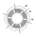
以下、このように構成された本発明の実施の形態を、図1乃至図4に基づいて説明する。まず、図1は、本発明の実施形態によるモータ固定子を示した平面図であり、図2は、図1のモータ固定子を示した側面図である。図1及び図2に示すように、固定子102内部の固定子スロットに固定子コイルが巻き取られた巻線部106が設けられ、巻線部106と固定子102との間に絶縁部104が形成される。巻線部106の上部には、各相(U、V、W)の相電流が供給される各線が突出され、巻線部106の下部には、各中性線108が突出される。中性線端子110は、これら中性線108を一つに締結して取り付けるために使用される。
Hereinafter, an embodiment of the present invention configured as described above will be described with reference to FIGS. First, FIG. 1 is a plan view showing a motor stator according to an embodiment of the present invention, and FIG. 2 is a side view showing the motor stator of FIG. As shown in FIGS. 1 and 2, a
図3は、図1のモータ固定子を示した回路図である。図3に示すように、電源を受けるために巻き取られた巻線部106では、各相(U、V、W)のコイルが一つの閉回路を形成し、各相の中性線は、中性線端子110により一つに締結されて電気的に連結される。
FIG. 3 is a circuit diagram showing the motor stator of FIG. As shown in FIG. 3, in the winding
図4は、図2の中性線端子を示した図であり、図4(A)は斜視図で、図4(B)は正面図で、図4(C)は側面図である。まず、図4(A)に示すように、本発明の実施形態による中性線端子110は、上部パネル110a、後部パネル110b、前部パネル110cおよび下部パネル110dにより構成される。上部パネル110a、後部パネル110bおよび下部パネル110dには、全ての中性線108を受容する受容部を形成し、前部パネル110cには、これら受容された各中性線108を圧着固定する固定部を形成する。
4 is a diagram showing the neutral wire terminal of FIG. 2, FIG. 4 (A) is a perspective view, FIG. 4 (B) is a front view, and FIG. 4 (C) is a side view. First, as shown in FIG. 4A, the
すなわち、上部パネル110aは、後部パネル110bの一端とほぼ直角をなして一体に連結される。また、前部パネル110cは、後部パネル110bの他端と屈曲をなして一体に連結される。これら上部パネル110a、後部パネル110bおよび前部パネル110cは、三つの中性線108を取り囲んでおり、下部パネル110dは、後部パネル110bの側面に上部パネル110aから所定距離離れて形成される。ここで、上部パネル110aと下部パネル110dとの間の距離は、三つの中性線108の直径の合計に当る距離であり、これら上部パネル110aおよび下部パネル110dにより、三つの中性線108が相互密着される。
That is, the
図4の中性線端子110は、一つの実施形態であり、多数の中性線を一時に一つに締結できる構造であれば、如何なる構造でも良い。また、上部パネル110aと下部パネル110dとの間の間隔は、必ず全ての中性線の直径の合計に制限されることなく、全ての中性線が、相互接触する状態で上部パネル110aと下部パネル110dとの間に受容される程度の間隔であればよい。このとき、前部パネル110cの長さは、上部パネル110aと下部パネル110dとの間に受容される全ての中性線108を前面で圧着固定できる程度の長さであることが好ましい。
The
前部パネル110cは、後部パネル110bと屈曲をなして設けられるが、これは、前部パネル110cを伸ばして上部パネル110aと下部パネル110dとの間に多数の中性線108を挿入した後、前部パネル110cを中性線108側に圧着することで、多数の中性線108を中性線端子110に密着固定するためである。このために、前部パネル110cと後部パネル110bとの間の連結部は、弾性を有することが好ましい。また、このような中性線端子110は、導体により形成するとともに、各中性線108を一時に一体に締結することで、電気的端子の役割を行う。
The
102 固定子
104 絶縁部
106 巻線部
108 中性線
110 中性線端子
102
Claims (6)
回転子と、
多数の中性線を有するとともに、多相の交流電源を受けて前記回転子を回転するための回転磁界を発生するように、前記固定子に設けられた巻線部と、
前記多数の中性線を一体に一時に締結するための単一の中性線端子とを含むモータであって、
前記中性線端子は、上部パネル、後部パネル、および下部パネルから構成され前記多数の中性線を全て受容する受容部と、前部パネルに形成され前記受容された中性線を圧着固定するための固定部とを含んで構成され、
前記上部パネルは、前記後部パネルの一端とほぼ直角をなして一体に連結され、
前記前部パネルは、前記後部パネルの他端と屈曲をなして一体に連結され、
前記下部パネルは、前記後部パネルの上記屈曲より上方の側面に形成されて前記前部パネル側に前記上部パネルとほぼ平行に延伸しており、前記上部パネルからの離間距離が前記受容部に収納する前記中性線の直径の合計に基づく距離とされていることを特徴とするモータ。 A stator,
A rotor,
A winding portion provided on the stator so as to generate a rotating magnetic field for rotating the rotor in response to a multiphase AC power source with a number of neutral wires,
A motor including a single neutral wire terminal for fastening the multiple neutral wires together at one time,
The neutral wire terminal is composed of an upper panel, a rear panel, and a lower panel, and receives a plurality of neutral wires. The neutral wire terminal is formed on the front panel and presses and fixes the received neutral wire. And a fixing part for
The upper panel is integrally connected with one end of the rear panel substantially at right angles,
The front panel is integrally connected with the other end of the rear panel by bending,
The lower panel is formed on a side surface above the bend of the rear panel and extends substantially parallel to the upper panel toward the front panel, and a distance from the upper panel is stored in the receiving portion. The distance is based on the total diameter of the neutral wires.
上部パネル、後部パネル、および下部パネルから構成され前記多数の中性線を全て受容する受容部と、
前部パネルに形成され前記受容された中性線を圧着固定するための固定部とを含んで構成され、
前記上部パネルは、前記後部パネルの一端とほぼ直角をなして一体に連結され、
前記前部パネルは、前記後部パネルの他端と屈曲をなして一体に連結され、
前記下部パネルは、後部パネルの上記屈曲より上方の側面に形成されて前記前部パネル側に前記上部パネルとほぼ平行に延伸しており、前記上部パネルからの離間距離が前記受容部に収納する前記中性線の直径の合計に対応する距離とされていることを特徴とするモータの中性線端子。 A neutral terminal of a motor for fastening a number of neutral wires of the motor,
A receiving portion that is composed of an upper panel, a rear panel, and a lower panel and receives all of the multiple neutral lines;
A fixing part for crimping and fixing the received neutral wire formed on the front panel,
The upper panel is integrally connected with one end of the rear panel substantially at right angles,
The front panel is integrally connected with the other end of the rear panel by bending,
The lower panel is formed on a side surface above the bend of the rear panel and extends substantially parallel to the upper panel on the front panel side, and a distance from the upper panel is accommodated in the receiving portion. The neutral wire terminal of the motor is characterized by a distance corresponding to the total diameter of the neutral wires.
Applications Claiming Priority (1)
| Application Number | Priority Date | Filing Date | Title |
|---|---|---|---|
| KR1020040083767A KR100854994B1 (en) | 2004-10-19 | 2004-10-19 | Motor and method of connecting neutral line |
Publications (2)
| Publication Number | Publication Date |
|---|---|
| JP2006121883A JP2006121883A (en) | 2006-05-11 |
| JP4101799B2 true JP4101799B2 (en) | 2008-06-18 |
Family
ID=36539233
Family Applications (1)
| Application Number | Title | Priority Date | Filing Date |
|---|---|---|---|
| JP2004377105A Active JP4101799B2 (en) | 2004-10-19 | 2004-12-27 | Motor, neutral wire terminal and method for fastening the neutral wire |
Country Status (3)
| Country | Link |
|---|---|
| JP (1) | JP4101799B2 (en) |
| KR (1) | KR100854994B1 (en) |
| CN (1) | CN100395943C (en) |
Families Citing this family (6)
| Publication number | Priority date | Publication date | Assignee | Title |
|---|---|---|---|---|
| KR100793807B1 (en) * | 2006-09-07 | 2008-01-11 | 엘지전자 주식회사 | Winding method for 3 phases and multiple poles motor and the motor using the same |
| JP5075620B2 (en) * | 2007-12-27 | 2012-11-21 | アスモ株式会社 | Terminal, connection structure between terminal and coil, armature, stator, motor, method for joining terminal and coil, and method for manufacturing stator |
| JP2013059156A (en) * | 2011-09-07 | 2013-03-28 | Hitachi Automotive Systems Ltd | Stator of rotary electric machine, and rotary electric machine |
| CN102723797A (en) * | 2012-06-26 | 2012-10-10 | 东方电气(乐山)新能源设备有限公司 | Novel neutral point jointing structure of wind driven generator rotor |
| CN107124057A (en) * | 2017-06-28 | 2017-09-01 | 佛山市威灵洗涤电机制造有限公司 | Machine winding and motor |
| KR102430382B1 (en) * | 2017-07-14 | 2022-08-08 | 엘지이노텍 주식회사 | Motor |
Family Cites Families (7)
| Publication number | Priority date | Publication date | Assignee | Title |
|---|---|---|---|---|
| KR0140172B1 (en) * | 1994-11-10 | 1998-08-17 | 이헌조 | Power connecting terminal fixing device of motor |
| JPH0937497A (en) * | 1995-07-18 | 1997-02-07 | Fuji Electric Co Ltd | Small-capacity ac motor of stator armature type |
| JPH09285057A (en) * | 1996-04-15 | 1997-10-31 | Sankyo Seiki Mfg Co Ltd | Lead wire holding structure in small motor |
| KR200151092Y1 (en) * | 1997-05-02 | 1999-07-15 | 김민박,라이문트하이넨 | Fixed device for motor read wire |
| JP2000232745A (en) * | 1999-02-10 | 2000-08-22 | Toshiba Kyaria Kk | Compressor motor |
| JP2001231205A (en) * | 2000-02-14 | 2001-08-24 | Mitsubishi Electric Corp | Stator of ac generator |
| KR20060034595A (en) * | 2004-10-19 | 2006-04-24 | 삼성전자주식회사 | Motor, neutral line connecting and connecting method thereof |
-
2004
- 2004-10-19 KR KR1020040083767A patent/KR100854994B1/en active IP Right Grant
- 2004-12-27 JP JP2004377105A patent/JP4101799B2/en active Active
-
2005
- 2005-01-14 CN CNB2005100039888A patent/CN100395943C/en not_active Expired - Fee Related
Also Published As
| Publication number | Publication date |
|---|---|
| KR20060034594A (en) | 2006-04-24 |
| CN100395943C (en) | 2008-06-18 |
| CN1764043A (en) | 2006-04-26 |
| JP2006121883A (en) | 2006-05-11 |
| KR100854994B1 (en) | 2008-08-28 |
Similar Documents
| Publication | Publication Date | Title |
|---|---|---|
| US9419491B2 (en) | Motor connecting member and motor device | |
| US20140091655A1 (en) | Bus Bar for Use in Electric Motor | |
| JP6676606B2 (en) | Method for producing a stator and a corresponding stator | |
| CN106104979B (en) | Insulator and the Brushless DC motor for using the insulator | |
| JP6444930B2 (en) | Electric motor provided with a wiring board configured by crimping and connecting windings | |
| US20150318768A1 (en) | Contact element for an electric machine | |
| JPH11178265A (en) | Stator for magnet generator | |
| DE502005000248D1 (en) | Stator for an electric machine | |
| JP2005341640A (en) | Stator of motor | |
| JP4914618B2 (en) | Stator | |
| JP2005130586A (en) | Stator of motor | |
| JP2007259553A (en) | Intensive power distribution component | |
| JP2015501125A (en) | Electrical machine with contact connector | |
| JP4101799B2 (en) | Motor, neutral wire terminal and method for fastening the neutral wire | |
| JP6447736B2 (en) | Rotating electrical terminal block | |
| US11101711B2 (en) | Brushless direct current motor, stator part and winding method thereof | |
| US8269386B2 (en) | Phase lead connections for a bar wound stator | |
| CN107689700B (en) | Stator and motor using same | |
| KR101146447B1 (en) | Bus-bar having connection tap for improving coil connection | |
| JP2006121884A (en) | Motor, neutral conductor fastening section and method fastening of motor | |
| KR100725738B1 (en) | Motor | |
| KR20140028967A (en) | The stator for motor | |
| WO2018163414A1 (en) | Dynamo-electric machine and method for manufacturing dynamo-electric machine | |
| US20230387743A1 (en) | Electrical drive unit | |
| CN103855834B (en) | The distribution processing construction of stator coil |
Legal Events
| Date | Code | Title | Description |
|---|---|---|---|
| A977 | Report on retrieval |
Free format text: JAPANESE INTERMEDIATE CODE: A971007 Effective date: 20060915 |
|
| A131 | Notification of reasons for refusal |
Free format text: JAPANESE INTERMEDIATE CODE: A131 Effective date: 20061017 |
|
| A521 | Written amendment |
Free format text: JAPANESE INTERMEDIATE CODE: A523 Effective date: 20070110 |
|
| A131 | Notification of reasons for refusal |
Free format text: JAPANESE INTERMEDIATE CODE: A131 Effective date: 20071002 |
|
| A521 | Written amendment |
Free format text: JAPANESE INTERMEDIATE CODE: A523 Effective date: 20071225 |
|
| TRDD | Decision of grant or rejection written | ||
| A01 | Written decision to grant a patent or to grant a registration (utility model) |
Free format text: JAPANESE INTERMEDIATE CODE: A01 Effective date: 20080304 |
|
| A61 | First payment of annual fees (during grant procedure) |
Free format text: JAPANESE INTERMEDIATE CODE: A61 Effective date: 20080319 |
|
| FPAY | Renewal fee payment (event date is renewal date of database) |
Free format text: PAYMENT UNTIL: 20110328 Year of fee payment: 3 |
|
| R150 | Certificate of patent or registration of utility model |
Ref document number: 4101799 Country of ref document: JP Free format text: JAPANESE INTERMEDIATE CODE: R150 Free format text: JAPANESE INTERMEDIATE CODE: R150 |
|
| FPAY | Renewal fee payment (event date is renewal date of database) |
Free format text: PAYMENT UNTIL: 20110328 Year of fee payment: 3 |
|
| R250 | Receipt of annual fees |
Free format text: JAPANESE INTERMEDIATE CODE: R250 |
|
| FPAY | Renewal fee payment (event date is renewal date of database) |
Free format text: PAYMENT UNTIL: 20120328 Year of fee payment: 4 |
|
| FPAY | Renewal fee payment (event date is renewal date of database) |
Free format text: PAYMENT UNTIL: 20130328 Year of fee payment: 5 |
|
| R250 | Receipt of annual fees |
Free format text: JAPANESE INTERMEDIATE CODE: R250 |
|
| FPAY | Renewal fee payment (event date is renewal date of database) |
Free format text: PAYMENT UNTIL: 20130328 Year of fee payment: 5 |
|
| FPAY | Renewal fee payment (event date is renewal date of database) |
Free format text: PAYMENT UNTIL: 20140328 Year of fee payment: 6 |
|
| R250 | Receipt of annual fees |
Free format text: JAPANESE INTERMEDIATE CODE: R250 |
|
| R250 | Receipt of annual fees |
Free format text: JAPANESE INTERMEDIATE CODE: R250 |
|
| R250 | Receipt of annual fees |
Free format text: JAPANESE INTERMEDIATE CODE: R250 |
|
| R250 | Receipt of annual fees |
Free format text: JAPANESE INTERMEDIATE CODE: R250 |
|
| R250 | Receipt of annual fees |
Free format text: JAPANESE INTERMEDIATE CODE: R250 |
|
| R250 | Receipt of annual fees |
Free format text: JAPANESE INTERMEDIATE CODE: R250 |
|
| R250 | Receipt of annual fees |
Free format text: JAPANESE INTERMEDIATE CODE: R250 |
|
| R250 | Receipt of annual fees |
Free format text: JAPANESE INTERMEDIATE CODE: R250 |