JP4100831B2 - Gap covering device for buildings with seismic isolation structure - Google Patents
Gap covering device for buildings with seismic isolation structure Download PDFInfo
- Publication number
- JP4100831B2 JP4100831B2 JP20288499A JP20288499A JP4100831B2 JP 4100831 B2 JP4100831 B2 JP 4100831B2 JP 20288499 A JP20288499 A JP 20288499A JP 20288499 A JP20288499 A JP 20288499A JP 4100831 B2 JP4100831 B2 JP 4100831B2
- Authority
- JP
- Japan
- Prior art keywords
- seismic isolation
- column
- panel
- earthquake
- wall
- Prior art date
- Legal status (The legal status is an assumption and is not a legal conclusion. Google has not performed a legal analysis and makes no representation as to the accuracy of the status listed.)
- Expired - Fee Related
Links
Images
Landscapes
- Building Environments (AREA)
- Buildings Adapted To Withstand Abnormal External Influences (AREA)
Description
【0001】
【発明の属する技術分野】
この発明に係る免震構造を有するビルディングの隙間覆い装置は、免震構造を有するビルディングの一部で、柱の下部で免震装置を設けた部分の直上部分に設ける。そして、免震構造を構成する為に必要とする隙間を確保しつつ、上記柱の周囲の空間の有効利用を図れる様にする。
【0002】
【従来の技術】
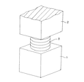
大地震の際にもビルディングの揺れを抑えて、このビルディングの倒壊を防止するだけでなく、このビルディング内の建具の転倒や配線、配管の損傷を防止する免震装置が、近年実用化されている。この様な免震装置は、上記ビルディングを支える総ての柱をそれぞれの中間部で分断し、分断部分に組み込む。即ち、図18に略示する様に、床面側に固定の下柱1の上端面と、この下柱1の上方に設けた上柱2の下端面との間に、免震装置3を設けている。地震の際にはこの免震装置3が、上記上柱2が上記下柱1に対し水平方向に相対変位する事を許容する。即ち、地震の際には、これら上柱2と下柱1とが水平方向に相対変位し、地面側に固定した基礎と共に揺れる下柱1の揺れが、建物側に固定した上柱2に伝わる事を防止する。
【0003】
上述の様な免震装置3は、ビルディングの基礎と地盤との間に設ける(基礎免震)他、基礎から上方に伸びた柱の中間部に設ける場合(中間階免震)もある。この様な中間階免震の場合には、免震装置を特定の階の中間部に設ける。この為、この特定の階の床面からは下柱1が突出し、同じく天井からは上柱2が垂れ下がった状態となる。これら下柱1と上柱2とが上記免震装置3を介して重なり合って、上記ビルディングを支える柱を構成する。又、上記特定の階の壁は、床面から立ち上げた状態で設けて、その上端縁は天井には固定せず、地震の際にこの天井と上記壁とが水平方向に亙り相対変位する様にする。又、この壁の水平方向端縁と上記上柱の側面との間には隙間をあけて、地震の際にも、これら端縁と側面とがぶつかり合う事がない様にしている。この様な隙間の大きさは、対応可能とすべき地震の大きさやビルディングの規模によっても異なるが、20〜40cm程度確保する必要がある。
【0004】
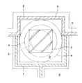
この様に大きな隙間をそのままにしておく事は、美観上も、防犯上も、室内の空気調和上もできない。この為に従来は、図19に示す様に、地震時に於ける上記上柱2の水平移動を十分に許容できるだけの内部容積を有するカバー4内に、上記下柱1(図18参照)と上柱2と免震装置3とを収納していた。図19に示した例では、上記カバー4を、屋内と屋外とを仕切る外壁5の中間部で上記各部材1、2、3に対向する部分から屋外側に突出した屋外側半部6と、この屋外側半部6と最中状に組み合わさった屋内側半部7とから構成している。そして、これら屋外側、屋内側両半部6、7により、中空四角筒状の上記カバー4を構成している。通常時に於ける上記上柱2の断面の最小外接円は、図19の鎖線αであるが、地震の際にこの上柱2が変位し得る範囲の最小外接円は、同じく鎖線βである。上記カバー4の内面は、この鎖線βを内部に納められるだけの大きさを有する。
【0005】
【発明が解決しようとする課題】
図19に示した様な従来構造の場合には、カバー4を構成する屋内側半部7が室内空間8側に大きく突出し、この室内空間8の有効面積を減少させてしまう。即ち、通常時に上記カバー4の内周面と上記上柱2の外周面との間には、大きな空間9が存在するが、この空間9は上記カバー4により室内空間8から仕切られたデッドスペースとなって、利用できない。
本発明は、免震装置3の円滑な作動を確保し、しかも地震の際に免震装置3の周囲に存在する部材が破損するのを防止しつつ、上述の様なデッドスペースの発生を抑える事で、空間の有効利用を図れる構造を実現するものである。
【0006】
【課題を解決するための手段】
本発明の免震構造を有するビルディングの隙間覆い装置は、床面側に固定の下柱の上端面とこの下柱の上方に設けた上柱の下端面との間に、地震の際にこの上柱がこの下柱に対し水平方向に相対変位する事を許容する免震装置を組み込んで成る免震柱と、上記床面側に固定されて地震の際にこの床面と共に変位する壁と、天井側に固定されて地震の際にこの天井と共に変位する上記上柱と、この上柱の側面と上記壁の水平方向端縁との間に水平方向に亙って存在する隙間と、これら上柱と壁との間に設けてこの隙間を覆うパネルとを備える。そして、このパネルは、これら上柱と壁との相対変位を吸収自在な構造を有するものである。
【0007】
【作用】
上述の様に構成する本発明の免震構造を有するビルディングの隙間覆い装置によれば、少なくともパネルを設けた側の上柱を、この上柱の外寸よりも十分に大きな内寸を有するカバーにより覆う必要がなくなる。この為、上記パネルを設けた側の空間の有効利用が可能になる。
【0008】
【発明の実施の形態】
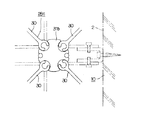
図1〜8は、本発明の実施の形態の第1例を示している。ビルディングの重量を支える複数本の免震柱10、10は、床面11から立ち上がった下柱1、1の上端面と、天井12から垂れ下がった上柱2、2の下端面との間に、免震装置3を挟持して成る。従って、地震の際には、地盤と共に水平方向に動く上記各下柱1、1に拘らず、上記各上柱2、2の動きが抑えられて、上記ビルディングのうちでこれら各上柱2、2よりも上側部分の揺れを抑える事ができる。上記各下柱1、1の上端面と上柱2、2の下端面との間で、上記免震装置3を設置した空間の周囲開口部は、セラミック等の耐火材製の耐火被覆13、13により覆って、火災発生時にも上記免震装置3を保護する様にしている。尚、図示は省略したが、これら各耐火被覆13、13は上下に2分割して水平方向にスライド自在とし、地震発生時に於ける上記各下柱1、1と各上柱2、2との相対変位に拘らず、上記各耐火被覆13、13が破損する事がない様にしている。
【0009】
隣り合う免震柱10、10同士の間には外壁5a、5aを設けて、図1の上側に相当する屋外と、同じく下側に相当する屋内とを仕切っている。これら各外壁5a、5aは、それぞれの基端部(下端部)を上記床面11に固定し、それぞれの先端部(上端部)は、上記天井12と分離している。又、上記各外壁5a、5aの水平方向両端縁部は、それぞれ上記各免震柱10、10の側面に対向させている。但し、これら各端縁部と側面との間には、それぞれ十分に隙間を介在させている。従って、地震の際には、上記各外壁5a、5aと、上記各免震柱10、10のうちの下柱1、1が、上記床面11と共に変位し、これら各免震柱10、10のうちの上柱2、2は、上記天井12と共に変位する。
【0010】
尚、図示の例では、上記外壁5aに開き戸14と引き違い窓15とを設けている。又、上記各免震柱10、10部分で不連続となっている、隣り合う外壁5a、5a同士の間には、これら各免震柱10、10の屋外側に位置する状態で、覆い壁16、16を設けている。そして、これら各覆い壁16、16により、隣り合う外壁5a、5a同士を、上記各免震柱10、10を屋外側に迂回する形で連続させている。上記各覆い壁16、16は、それぞれが前述の図19に示した従来構造に於ける、カバー4の屋外側半部6に相当するもので、コ字形の横断面形状を有する。この様な各覆い壁16、16はそれぞれ、地震発生時に上記各上柱2、2がこれら各覆い壁16、16に対し水平方向に相対変位した場合でも、これら各上柱2、2の外周面と各覆い壁16、16の内周面とがぶつからない程度の内寸を有する。
【0011】
尚、この様な各覆い壁16、16は、上記各上柱2、2に対向する部分に設ければ足りる。言い換えれば、上記各下柱1、1に対応する部分には、上記各覆い壁16、16を設ける必要はなく、単に外壁5aを上記各下柱1、1の側面に突き当てれば良い。但し、この様な構造を採用すると、上記各覆い壁16、16が、上記外壁5aの屋外面の高さ方向中間部から屋外側に突出する状態となる。従って、この様な状態が好ましくなければ、上記各覆い壁16、16を、上記各下柱1、1の下端部まで覆う状態に、下方にまで設けても良い。これに対して、屋外側で前記床面11と同じ部分の有効利用を図るのであれば、上記各覆い壁16、16を、上記各上柱2、2に対向する部分にのみ設ける。何れにしても、これら各覆い壁16、16の屋内側開口部両端縁と上記各上柱2、2の側面との間には、地震発生時に於けるこれら各上柱2、2の水平方向に亙る相対変位を許容できるだけの隙間17、17が存在する。尚、図示の例では、上記各覆い壁16、16は、上記各下柱1、1の下端部まで、上記各免震柱10、10の全高に亙り設けている。
【0012】
そして、上記各隙間17、17部分に上部パネル18、18と下部パネル19、19とを設けて、これら各隙間17、17を覆っている。これら上部、下部両パネル18、19のうちの、請求項に記載したパネルに相当する、上部パネル18、18は、上記各上柱2、2の側面と上記外壁5a、5aの上部端縁との相対変位を吸収自在な構造を有する。この為に本例の場合には、上記各上部パネル18、18を、水平方向に亙り互いに直列に配置された1対のパネル素子20a、20bの一端縁同士を、ばね付で表裏両方向に亙る揺動変位を許容する自由蝶番21、21で連結する事により構成している。
【0013】
これら各自由蝶番21、21は、図7に示す様に、中間連結板22の両端部にそれぞれ取付板23a、23bを、枢軸24、24を中心とする揺動変位自在に結合し、これら各枢軸24、24の周囲に捩りコイルばね等の復位ばね25、25を組み付けて成る。これら各復位ばね25、25は上記各取付板23a、23bのうちの一方の取付板23aを上記中間連結板22の表面側に、他方の取付板23bを同じく裏面側に、それぞれ折り畳む方向の弾力を有する。この様な構成を有する上記各自由蝶番21、21は、外力が作用しない場合には、図4、6に示す様に折り畳まれた状態となるが、外力が作用すると、これら4、6に示した状態から図7に示した状態、更にはこの図7の状態を越えて変位する。
【0014】
上記1対のパネル素子20a、20bは、上記各自由蝶番21、21を構成する一方の取付板23aを一方のパネル素子20aの一端縁部に、同じく他方の取付板23bを他方のパネル素子20bの一端縁部に、それぞれねじ止め固定する事で、互いの揺動変位自在に連結する。尚、この状態で、上記各自由蝶番21、21を構成する1対の枢軸24、24は、それぞれ上記各パネル素子20a、20bの表裏面から突出する。この様にして上記各自由蝶番21、21により互いに連結した、上記1対のパネル素子20a、20bは、一方のパネル素子20aの表面側に他方のパネル素子20bが重なり合っている状態から、この一方のパネル素子20aの裏面側に他方のパネル素子20bが重なり合っている状態にまで、ほぼ360度に亙る相対変位自在である。但し、外力が作用していない状態では、図4、6に示す様に、上記1対のパネル素子20a、20b同士が、同一平面上に位置する。
【0015】
上述の様に構成する上記上部パネル18は、上記一方のパネル素子20aの他端縁部を、前記覆い壁16の屋内側開口部両端縁に、上述した様な自由蝶番21、21により、揺動変位自在に支持している。これに対して、上記他方のパネル素子20bの他端縁は、前記免震柱10の側面に対向させている。図示の例では、上記他方のパネル20bの屋外側面他端縁部に突き当て枠26の基端部を固定し、この突き当て枠26の先端縁を、上記免震柱10の側面に突き当てている。尚、図示は省略するが、上記突き当て枠26の先端縁部には、必要に応じてパッキング等の気密材を添設する。何れにしても、この突き当て枠26の先端縁部と上記免震柱10の側面との当接部は、上記上部パネル18の屋外側面よりも更に外方にずれた位置に存在する。従って、上記免震柱10が上記突き当て枠26を押圧する方向に変位すると、上記上部パネル18は、上記各自由蝶番21、21を中心に座屈する様に折れ曲がって、この上部パネル18自身を何ら損傷する事なく、上記免震柱10の変位を許容する。尚、図示の例では、上記上部パネル18を、前記耐火被覆13を挟み、前記上柱2の上部側面から前記下柱1の上端部側面に亙る部分に対向させている。
【0016】
更に、上記上部パネル18の下方には、前記下部パネル19を設けている。これら両パネル18、19は、通常状態で互いに同一平面上に位置する。そして、上記下部パネル19により、前記各覆い壁16、16の屋内側開口部両端縁と各上柱2、2の側面との間に存在する隙間17、17のうち、上記上部パネル18により覆われない部分を塞いでいる。上記下部パネル19を設ける部分では、地震時にも上記各隙間17、17の幅が変化する事はないので、上記下部パネル19は、幅寸法が変化しない単体構造で良い。更には、前記各下柱1、1の上端面よりも下側部分では、前記各外壁5a、5aをこれら各下柱1、1の側面まで、若しくはこの側面の近傍まで延長して、上記下側部分に隙間を設けない様にする事もできる。この場合には、上記各下柱1、1の側方には、隙間を覆う為のパネルを設ける必要はなくなる。尚、これら各下柱1、1の側方にも隙間17、17を介在させる場合、上記上部パネル18の構造を、上記各隙間17、17の上端から下端に至るまで設けても良い。但し、コストが嵩む為、図示の例では、変位吸収の必要がない部分は、構造が簡単な下部パネル19とした。
【0017】
上述の様に構成する本例の免震構造を有するビルディングの隙間覆い装置によれば、上記上部パネル18と下部パネル19とが、上記各覆い壁16、16の屋内側開口部両端縁と上記各免震柱10、10の側面との間に存在する隙間17、17を覆う。これら各免震柱10、10の設置部分を室内側から見た場合の美観、並びに室内空間の空調は、上記各パネル18、19の存在に基づき問題がなくなる。又、防犯上の問題は、上記各覆い壁16、16がビルディングの内外を仕切る為、問題を生じる事はない。この様に本発明によれば、上記各免震柱10、10の屋内側を、これら各免震柱10、10の外寸よりも十分に大きな内寸を有するカバーにより覆う必要がなくなる。この為、上記各免震柱10、10の屋内側部分の空間の有効利用が可能になる。
【0018】
地震発生の際には、図8に示す様にして、上記覆い壁16に対する前記上柱2の相対変位を許容する。即ち、通常時には図8(A)に示す様に、この上柱2が上記覆い壁16の屋内側開口部中央に位置して、上記上部パネル18、18が上記隙間17、17を覆っている。これに対して、地震発生時には、上記上柱2が上記覆い壁16に対して変位する。この変位の方向は予測できず、例えば図8(B)〜(F)に矢印で示す様に、あらゆる方向に変位する可能性がある。これに対して、本例の場合には、上記上柱2が何れの方向に変位した場合でも、上記各免震柱10、10の両側に1対ずつ設けた上部パネル18、18のうちの何れかの上部パネル18を構成するパネル素子20a、20b同士が相対変位する事により、或は上記上柱2が両上部パネル18、18に対して摺動する事により、この上柱2の変位を許容する。この場合に、これら各上部パネル18、18が損傷を受ける事はない。
【0019】
次に、図9は、本発明の実施の形態の第2例を示している。本例の場合には、免震柱10の屋内側に、屋内を複数の部屋に仕切る為の仕切壁27を、この免震柱10の屋内側面と直交する方向に形成している。この仕切壁27も、屋内と屋外とを仕切る外壁5b、5bと同様に、床面側に固定し、天井面に対し相対変位自在としている。従って地震発生時には、上記免震柱10と仕切壁27とが相対変位する。そこで、本例の場合には、この免震柱10の屋内側面と仕切壁27の端縁との間に、上述した第1例の場合と同様の上部パネル18を設けている。この上部パネル18は、通常時に上記仕切壁27により仕切られる部屋同士の間仕切りを行ないつつ、地震発生時には、この仕切壁27と上記免震柱10との相対変位を許容する。その他の構成及び作用は、上述した第1例の場合と同様である。
【0020】
次に、図10は、本発明の実施の形態の第3例を示している。本例の場合には、外壁5a、5aの端縁と免震柱10を構成する上柱2の側面との間の隙間17、17を覆う為のパネル28、28を、上記各外壁5a、5aに沿う水平移動自在に設けている。これら各パネル28、28と外壁5a、5aとの間には、これら各パネル28、28を上記上柱2の側面に向け弾性的に押圧する為の押圧機構を設けている。この押圧機構としては、ばねを内蔵したダンパシリンダ等、従来から各種用途に使用されている押圧装置を利用できる。
【0021】
この様な本例の場合、通常時には図10(A)に示す様に、上記上柱2が水平方向に隣り合う1対の外壁5a、5a同士の間に存在する不連続部の中央に位置して、上記各パネル28、28が上記各隙間17、17を覆っている。これに対して、地震発生時には、上柱2が上記各外壁5a、5aに対して変位する。この変位の方向は例えば図10(B)〜(F)に矢印で示す様に、あらゆる方向に亙るが、上記上柱2が何れの方向に変位した場合でも、上記上柱2の両側に1対ずつ設けたパネル28、28が水平移動する事により、或はこの上柱2がこれら両パネル28、28に対して摺動する事により、この上柱2の変位を許容する。この場合に、これら各パネル28、28が損傷を受ける事はない。本例の場合には、これら各パネル28、28の幅寸法及び上記押圧装置のストロークを十分に確保すれば、地震発生時にも、上記上柱2の側面と上記各外壁5a、5aの端縁との間に、見通せる様な隙間が生じる事はない。その他の構成及び作用は、前述した第1例の場合と同様であるから、重複する図示並びに説明は省略する。
【0022】
次に、図11は、本発明の実施の形態の第4例を示している。本例の場合には、外壁5cを二重構造とし、この外壁5cの内部にパネル28aを、水平方向の変位自在に組み込んでいる。従って、このパネル28aの設置部分の体裁を良くできる。その他の構成及び作用は、上述した第3例の場合と同様であるから、重複する図示並びに説明は省略する。
【0023】
次に、図12は、本発明の実施の形態の第5例を示している。本例の場合には、外壁5a、5aの端縁と免震柱10を構成する上柱2の側面との間の隙間17、17を覆う為のパネル28b、28bを、それぞれ1対のパネル素子29a、29bを組み合わせる事により構成している。この様な本例の場合には、これら各パネル素子29a、29bのうちの一方のパネル素子29a、29aを、上記各外壁5a、5aに対し水平移動自在に支持すると共に、他方のパネル素子29b、29bを、上記各一方のパネル素子29a、29aに対し水平移動自在に組み合わせている。そして、これら一方のパネル素子29a、29aと外壁5a、5aとの間に、これら各一方のパネル素子29a、29aを上記各上柱2の側面に向け弾性的に押圧する為の押圧機構を設け、これら各パネル素子29a、29aと上記各他方のパネル29b、29bとの間に、これら各他方のパネル29b、29bを上記各上柱2の側面に向け弾性的に押圧する為の押圧機構を設けている。
【0024】
この様な本例の構造の場合には、上記各パネル28b、28bの幅寸法を確保すると共に、上記各外壁5a、5aに対する上記各他方のパネル素子29b、29bのストロークを確保する事が容易になり、地震発生時にも、上記上柱2の側面と上記各外壁5a、5aの端縁との間に、見通せる様な隙間が生じる事をより確実に防止できる。その他の構成及び作用は、前述した第1例の場合と同様であるから、重複する図示並びに説明は省略する。
【0025】
次に、図13〜15は、本発明の実施の形態の第6例を示している。本例の場合には、外壁5a、5aの端縁と免震柱10を構成する上柱2の側面との間の隙間17、17を覆う為のパネル28c、28cを、アコーデオン式に伸縮自在な構造を有するものとしている。この様にアコーデオン式に伸縮自在な構造としては、従来から知られている各種構造のものを使用できるが、図示の例では、合成樹脂或はアルミニウム合金を押し出し成形する事により造る板材30、30の端縁部を、同様にして造った結合片31a、31bに揺動変位自在に嵌合連結する事により構成している。この様なパネル28c、28cの両端縁部は、上記上柱2の側面と上記各外壁5a、5aの端縁とに、それぞれ図示しない枢軸を中心とする揺動変位自在に結合している。
【0026】
この様な本例の場合、通常時には図13(A)に示す様に、上記上柱2が水平方向に隣り合う1対の外壁5a、5a同士の間に存在する不連続部の中央に位置して、上記各パネル28c、28cが上記各隙間17、17を覆っている。これに対して、地震発生時には、上柱2が上記各外壁5a、5aに対して変位する。この変位の方向は例えば図13(B)〜(F)に矢印で示す様に、あらゆる方向に亙るが、上記上柱2が何れの方向に変位した場合でも、上記上柱2の両側に1対ずつ設けたパネル28c、28cが伸縮、或は伸縮しつつ揺動変位する事により、この上柱2の変位を許容する。この場合に、これら各パネル28c、28cが損傷を受ける事はない。その他の構成及び作用は、前述した第1例の場合と同様であるから、重複する図示並びに説明は省略する。
【0027】
尚、上述の説明は、免震柱を構成する上柱の側面と外壁等の壁の水平方向端縁との間部分の隙間を覆う、本発明の対象となる構造に就いて行なった。但し、図16〜17に示す、本発明に関する参考例の様に、床面から上方に立ち上がった立ち上がり壁32、32aの一部と、天井から下方に垂れ下がった垂れ下がり壁33、33aの一部との間に、水平方向に亙って存在する隙間17aを塞ぐ為に利用する事もできる。
【0028】
【発明の効果】
本発明の免震構造を有するビルディングの隙間覆い装置は、以上に述べた通り構成され作用するので、免震柱の周囲に存在する余分なスペースを抑えて、空間の有効利用を図れる。
【図面の簡単な説明】
【図1】本発明の実施の形態の第1例を示す、図2のイ−イ断面図。
【図2】図1の下方(屋内側)から見た正面図。
【図3】図2のロ部斜視図。
【図4】図1のハ部拡大図。
【図5】上部パネルの正面図。
【図6】図5の拡大ニ−ニ断面図。
【図7】自由蝶番に外力を加えて引き伸ばした状態で示しており、(A)は平面図、(B)は正面図。
【図8】通常状態及び地震に伴う変位状態を示す部分略横断面図。
【図9】本発明の実施の形態の第2例を示す、図1の右部に相当する図。
【図10】同第3例を、通常状態及び地震に伴う変位状態で示す部分略横断面図。
【図11】同第4例を示す、図10(A)の左部に相当する図。
【図12】同第5例を、通常状態及び地震に伴う変位状態で示す部分略横断面図。
【図13】同第6例を、通常状態及び地震に伴う変位状態で示す部分略横断面図。
【図14】図13のホ部拡大図。
【図15】同ヘ部拡大図。
【図16】 本発明に関する参考例であり、パネルで塞ぐべき隙間の別例を示す為の略横断平面図。
【図17】同じく部分縦断略側面図。
【図18】免震柱の部分斜視図。
【図19】従来構造の1例を示す、図1の右部に相当する図。
【符号の説明】
1 下柱
2 上柱
3 免震装置
4 カバー
5、5a、5b、5c 外壁
6 屋外側半部
7 屋内側半部
8 室内空間
9 空間
10 免震柱
11 床面
12 天井
13 耐火被覆
14 開き戸
15 引き違い窓
16 覆い壁
17、17a 隙間
18 上部パネル
19 下部パネル
20a、20b パネル素子
21 自由蝶番
22 中間連結板
23a、23b 取付板
24 枢軸
25 復位ばね
26 突き当て枠
27 仕切壁
28、28a、28b、28c パネル
29a、29b パネル素子
30 板材
31a、31b 結合片
32、32a 立ち上がり壁
33、33a 垂れ下がり壁[0001]
BACKGROUND OF THE INVENTION
A gap covering device for a building having a seismic isolation structure according to the present invention is a part of a building having a seismic isolation structure, and is provided at a portion directly above a portion where a seismic isolation device is provided at a lower part of a column. And while ensuring the clearance required in order to comprise a seismic isolation structure, it enables it to aim at the effective utilization of the space around the said pillar.
[0002]
[Prior art]
In recent years, seismic isolation devices have been put into practical use not only to prevent the building from collapsing in the event of a major earthquake, but also to prevent the fittings in the building from falling over, wiring and piping. Yes. Such a seismic isolation device divides all the pillars that support the building at each intermediate portion and incorporates them into the divided portion. That is, as schematically shown in FIG. 18, the
[0003]
The
[0004]
It is impossible to keep such a large gap as it is for aesthetics, crime prevention, and indoor air conditioning. For this reason, conventionally, as shown in FIG. 19, the
[0005]
[Problems to be solved by the invention]
In the case of the conventional structure as shown in FIG. 19, the
The present invention ensures the smooth operation of the
[0006]
[Means for Solving the Problems]
The gap covering device for a building having a seismic isolation structure according to the present invention is provided between an upper end surface of a lower column fixed on a floor surface side and a lower end surface of an upper column provided above the lower column. A seismic isolation column that incorporates a seismic isolation device that allows the upper column to be displaced relative to the lower column in the horizontal direction, and a wall that is fixed to the floor and is displaced together with the floor in the event of an earthquake. The upper pillar fixed to the ceiling side and displaced together with the ceiling in the event of an earthquake, the gap existing between the side surface of the upper pillar and the horizontal edge of the wall in the horizontal direction , and these A panel provided between the upper column and the wall to cover the gap. And this panel has a structure which can absorb the relative displacement of these upper pillars and walls .
[0007]
[Action]
According to the gap covering device for a building having the seismic isolation structure of the present invention configured as described above, at least the upper column on the side where the panel is provided has a cover having an inner dimension sufficiently larger than the outer dimension of the upper column. Eliminates the need for covering. For this reason, the space on the side where the panel is provided can be used effectively.
[0008]
DETAILED DESCRIPTION OF THE INVENTION
1 to 8 show a first example of the embodiment of the present invention . A plurality of
[0009]
[0010]
In the illustrated example, the hinged
[0011]
It should be noted that it is sufficient to provide each of the covering
[0012]
Then , the
[0013]
As shown in FIG. 7, each of these
[0014]
In the pair of
[0015]
The
[0016]
Further, the
[0017]
According to the gap covering apparatus for a building having the seismic isolation structure of the present example configured as described above, the
[0018]
When an earthquake occurs, relative displacement of the
[0019]
Next, FIG. 9 shows a second example of the embodiment of the present invention . In the case of this example, a
[0020]
Next, FIG. 10 shows a third example of the embodiment of the present invention . In the case of this example, the
[0021]
In the case of this example, as shown in FIG. 10A, the
[0022]
Next, FIG. 11 shows a fourth example of the embodiment of the present invention . In the case of this example, the outer wall 5c has a double structure, and the
[0023]
Next, FIG. 12 shows a fifth example of the embodiment of the present invention . In the case of this example, the
[0024]
In the case of such a structure of this example, it is easy to ensure the width of the
[0025]
Next, FIGS. 13 to 15 show a sixth example of the embodiment of the present invention . In the case of this example, the
[0026]
In the case of this example, normally, as shown in FIG. 13A, the
[0027]
In addition, the above description was given about the structure used as the object of this invention which covers the clearance gap between the side surface of the upper pillar which comprises a seismic isolation column, and the horizontal direction edge of walls, such as an outer wall. However, like the reference examples related to the present invention shown in FIGS. 16 to 17, a part of the rising
[0028]
【The invention's effect】
Since the building gap covering apparatus having the seismic isolation structure of the present invention is configured and operates as described above, the extra space existing around the seismic isolation column can be suppressed to effectively use the space.
[Brief description of the drawings]
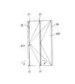
FIG. 1 is a cross-sectional view taken along the line II in FIG. 2, showing a first example of an embodiment of the present invention.
FIG. 2 is a front view seen from below (indoor side) of FIG.
FIG. 3 is a perspective view of a portion B in FIG. 2;
FIG. 4 is an enlarged view of a portion C in FIG. 1;
FIG. 5 is a front view of an upper panel.
6 is an enlarged knee sectional view of FIG. 5;
FIGS. 7A and 7B show a state in which the free hinge is stretched by applying an external force, where FIG. 7A is a plan view and FIG. 7B is a front view.
FIG. 8 is a partial schematic cross-sectional view showing a normal state and a displacement state associated with an earthquake.
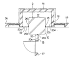
FIG. 9 is a diagram corresponding to the right side of FIG. 1, showing a second example of an embodiment of the present invention.
FIG. 10 is a partial schematic cross-sectional view showing the third example in a normal state and a displacement state associated with an earthquake.
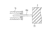
FIG. 11 is a view corresponding to the left part of FIG. 10 (A), showing the fourth example.
FIG. 12 is a partial schematic cross-sectional view showing the fifth example in a normal state and a displacement state accompanying an earthquake.
FIG. 13 is a partial schematic cross-sectional view showing the sixth example in a normal state and a displacement state associated with an earthquake.
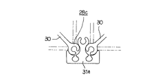
14 is an enlarged view of a portion E in FIG. 13;
FIG. 15 is an enlarged view of the same portion.
FIG. 16 is a schematic cross-sectional plan view showing another example of a gap to be closed with a panel, which is a reference example related to the present invention .
FIG. 17 is a schematic side view of the same partially vertical section.
FIG. 18 is a partial perspective view of a seismic isolation column.
FIG. 19 is a diagram corresponding to the right part of FIG. 1, showing an example of a conventional structure.
[Explanation of symbols]
DESCRIPTION OF
Claims (1)
Priority Applications (1)
| Application Number | Priority Date | Filing Date | Title |
|---|---|---|---|
| JP20288499A JP4100831B2 (en) | 1999-07-16 | 1999-07-16 | Gap covering device for buildings with seismic isolation structure |
Applications Claiming Priority (1)
| Application Number | Priority Date | Filing Date | Title |
|---|---|---|---|
| JP20288499A JP4100831B2 (en) | 1999-07-16 | 1999-07-16 | Gap covering device for buildings with seismic isolation structure |
Publications (3)
| Publication Number | Publication Date |
|---|---|
| JP2001032390A JP2001032390A (en) | 2001-02-06 |
| JP2001032390A5 JP2001032390A5 (en) | 2006-05-25 |
| JP4100831B2 true JP4100831B2 (en) | 2008-06-11 |
Family
ID=16464807
Family Applications (1)
| Application Number | Title | Priority Date | Filing Date |
|---|---|---|---|
| JP20288499A Expired - Fee Related JP4100831B2 (en) | 1999-07-16 | 1999-07-16 | Gap covering device for buildings with seismic isolation structure |
Country Status (1)
| Country | Link |
|---|---|
| JP (1) | JP4100831B2 (en) |
Cited By (4)
| Publication number | Priority date | Publication date | Assignee | Title |
|---|---|---|---|---|
| JPH071530A (en) * | 1993-06-21 | 1995-01-06 | Japan Steel Works Ltd:The | How to set molding conditions for injection molding machine |
| US7794494B2 (en) | 2002-10-11 | 2010-09-14 | Boston Scientific Scimed, Inc. | Implantable medical devices |
| US7976936B2 (en) | 2002-10-11 | 2011-07-12 | University Of Connecticut | Endoprostheses |
| US8043361B2 (en) | 2004-12-10 | 2011-10-25 | Boston Scientific Scimed, Inc. | Implantable medical devices, and methods of delivering the same |
Families Citing this family (4)
| Publication number | Priority date | Publication date | Assignee | Title |
|---|---|---|---|---|
| JP3925103B2 (en) * | 2000-07-27 | 2007-06-06 | 敏雄 藤岡 | Wall structure of seismic isolation structure |
| ES2237292B1 (en) * | 2003-02-05 | 2009-06-04 | F. Javier Porras Vila | ANTISISMIC COLUMN IMPROVED FOR CONSTRUCTION. |
| JP4834889B2 (en) * | 2006-06-05 | 2011-12-14 | 三井住友建設株式会社 | Intermediate floor curtain wall for base-isolated building |
| TWI751095B (en) * | 2021-08-06 | 2021-12-21 | 財團法人國家實驗研究院 | Dual-core self-resetting energy dissipation support device with compressed elastic unit |
-
1999
- 1999-07-16 JP JP20288499A patent/JP4100831B2/en not_active Expired - Fee Related
Cited By (6)
| Publication number | Priority date | Publication date | Assignee | Title |
|---|---|---|---|---|
| JPH071530A (en) * | 1993-06-21 | 1995-01-06 | Japan Steel Works Ltd:The | How to set molding conditions for injection molding machine |
| US7794494B2 (en) | 2002-10-11 | 2010-09-14 | Boston Scientific Scimed, Inc. | Implantable medical devices |
| US7976936B2 (en) | 2002-10-11 | 2011-07-12 | University Of Connecticut | Endoprostheses |
| US8784465B2 (en) | 2002-10-11 | 2014-07-22 | Boston Scientific Scimed, Inc. | Implantable medical devices |
| US9115245B2 (en) | 2002-10-11 | 2015-08-25 | Boston Scientific Scimed, Inc. | Implantable medical devices |
| US8043361B2 (en) | 2004-12-10 | 2011-10-25 | Boston Scientific Scimed, Inc. | Implantable medical devices, and methods of delivering the same |
Also Published As
| Publication number | Publication date |
|---|---|
| JP2001032390A (en) | 2001-02-06 |
Similar Documents
| Publication | Publication Date | Title |
|---|---|---|
| AU723109B2 (en) | Screen apparatus | |
| JP4100831B2 (en) | Gap covering device for buildings with seismic isolation structure | |
| US2915115A (en) | Sound retardant flexible room divider | |
| RU2454522C2 (en) | System of sliding windows of multi-storey building | |
| US2903055A (en) | Sound insulated folding door | |
| KR101686471B1 (en) | Joint structure for folding door | |
| JP7390859B2 (en) | fittings | |
| JP2001032390A5 (en) | ||
| JP2987293B2 (en) | Building exterior | |
| KR102742365B1 (en) | Interlocking door assembly for dividing and extending space | |
| JP5541728B2 (en) | Damping structure of wooden buildings | |
| KR20180109830A (en) | Folding door construction method | |
| US4537000A (en) | Thermal insulating window for application in curtain walls | |
| JPH09242444A (en) | Composite movable connecting device and manufacture therefor | |
| JP2513005Y2 (en) | Interlocking structure between partitions and walls of buildings | |
| JPH0526201Y2 (en) | ||
| KR102038988B1 (en) | Modular container booth with anti-vibration module with height adjustment function | |
| JP2012233334A (en) | Seismic isolated sash frame | |
| JP3079365B2 (en) | Seismic isolation structure | |
| JP2000320178A (en) | Movable mechanism between column walls in base-isolated building | |
| KR102805603B1 (en) | Modular expandable container with earthquake resistant structures | |
| JP4135225B2 (en) | Vibration control structure of building frame | |
| JP7373967B2 (en) | fittings | |
| JPH0528273Y2 (en) | ||
| KR100357483B1 (en) | indoor structure of house having a folding door |
Legal Events
| Date | Code | Title | Description |
|---|---|---|---|
| A521 | Written amendment |
Free format text: JAPANESE INTERMEDIATE CODE: A523 Effective date: 20060403 |
|
| A621 | Written request for application examination |
Free format text: JAPANESE INTERMEDIATE CODE: A621 Effective date: 20060403 |
|
| A977 | Report on retrieval |
Free format text: JAPANESE INTERMEDIATE CODE: A971007 Effective date: 20071018 |
|
| A131 | Notification of reasons for refusal |
Free format text: JAPANESE INTERMEDIATE CODE: A131 Effective date: 20071225 |
|
| A521 | Written amendment |
Free format text: JAPANESE INTERMEDIATE CODE: A523 Effective date: 20080215 |
|
| TRDD | Decision of grant or rejection written | ||
| A01 | Written decision to grant a patent or to grant a registration (utility model) |
Free format text: JAPANESE INTERMEDIATE CODE: A01 Effective date: 20080318 |
|
| A61 | First payment of annual fees (during grant procedure) |
Free format text: JAPANESE INTERMEDIATE CODE: A61 Effective date: 20080318 |
|
| FPAY | Renewal fee payment (event date is renewal date of database) |
Free format text: PAYMENT UNTIL: 20110328 Year of fee payment: 3 |
|
| R150 | Certificate of patent or registration of utility model |
Ref document number: 4100831 Country of ref document: JP Free format text: JAPANESE INTERMEDIATE CODE: R150 Free format text: JAPANESE INTERMEDIATE CODE: R150 |
|
| FPAY | Renewal fee payment (event date is renewal date of database) |
Free format text: PAYMENT UNTIL: 20110328 Year of fee payment: 3 |
|
| FPAY | Renewal fee payment (event date is renewal date of database) |
Free format text: PAYMENT UNTIL: 20120328 Year of fee payment: 4 |
|
| R250 | Receipt of annual fees |
Free format text: JAPANESE INTERMEDIATE CODE: R250 |
|
| FPAY | Renewal fee payment (event date is renewal date of database) |
Free format text: PAYMENT UNTIL: 20120328 Year of fee payment: 4 |
|
| FPAY | Renewal fee payment (event date is renewal date of database) |
Free format text: PAYMENT UNTIL: 20130328 Year of fee payment: 5 |
|
| R250 | Receipt of annual fees |
Free format text: JAPANESE INTERMEDIATE CODE: R250 |
|
| FPAY | Renewal fee payment (event date is renewal date of database) |
Free format text: PAYMENT UNTIL: 20130328 Year of fee payment: 5 |
|
| S531 | Written request for registration of change of domicile |
Free format text: JAPANESE INTERMEDIATE CODE: R313532 |
|
| FPAY | Renewal fee payment (event date is renewal date of database) |
Free format text: PAYMENT UNTIL: 20130328 Year of fee payment: 5 |
|
| R350 | Written notification of registration of transfer |
Free format text: JAPANESE INTERMEDIATE CODE: R350 |
|
| R250 | Receipt of annual fees |
Free format text: JAPANESE INTERMEDIATE CODE: R250 |
|
| R250 | Receipt of annual fees |
Free format text: JAPANESE INTERMEDIATE CODE: R250 |
|
| R250 | Receipt of annual fees |
Free format text: JAPANESE INTERMEDIATE CODE: R250 |
|
| R250 | Receipt of annual fees |
Free format text: JAPANESE INTERMEDIATE CODE: R250 |
|
| R250 | Receipt of annual fees |
Free format text: JAPANESE INTERMEDIATE CODE: R250 |
|
| R250 | Receipt of annual fees |
Free format text: JAPANESE INTERMEDIATE CODE: R250 |
|
| LAPS | Cancellation because of no payment of annual fees |


