JP4100478B2 - Game machine game board - Google Patents
Game machine game board Download PDFInfo
- Publication number
- JP4100478B2 JP4100478B2 JP35989597A JP35989597A JP4100478B2 JP 4100478 B2 JP4100478 B2 JP 4100478B2 JP 35989597 A JP35989597 A JP 35989597A JP 35989597 A JP35989597 A JP 35989597A JP 4100478 B2 JP4100478 B2 JP 4100478B2
- Authority
- JP
- Japan
- Prior art keywords
- outer rail
- game board
- hit ball
- game
- mounting piece
- Prior art date
- Legal status (The legal status is an assumption and is not a legal conclusion. Google has not performed a legal analysis and makes no representation as to the accuracy of the status listed.)
- Expired - Fee Related
Links
Images


Description
【0001】
【発明の属する技術分野】
この発明は、遊技機の遊技盤に関し、特に遊技機本体から遊技盤のみを取り外して交換可能な所謂分離式遊技機の遊技盤において、安定した打球発射を得られるようにした遊技機の遊技盤に関するものである。
【0002】
【従来の技術】
遊技機の遊技盤において、打球発射装置から発射された打球は、発射レールからファール玉樋を飛び越えて外レールに着弾し、この外レールに導かれて遊技部に飛入する。そして、従来の外レールは、一般に、基端部分を折曲加工して固定釘が通る筒状固定部を形成し、この固定部に通した固定釘をベニア合板からなる遊技盤本体に打ち込んで固定していた。また、従来の外レールは、適宜な間隔で下縁に係止させた割ピンを遊技盤本体に打ち込んで固定していた。
一方、打球をガラス面や遊技盤面に衝突させないで遊技部へ誘導するには、固定した外レールを遊技盤本体に対して所定の角度で起立させなければならない。そこで、従来は、上記した固定釘を側方からハンマー等で叩いて、外レールの取付角度を調整していた。
【0003】
【発明が解決しようとする課題】
上記外レールの取付角度、即ち、遊技盤面に対する外レールの起立状態は、打球の飛びに微妙に影響するので、所定の角度に調整しなければならない。
しかしながら、この調整は、前記したように固定釘をハンマー等で叩いて行っていたので、熟練技術を必要としていた。また、この調整作業は、狭い作業空間で行わなければならないため、誤って他の部材や組立機械を叩いてしまい、当該遊技盤を使用不能にしたり、組立機械を破損することもあった。
本発明は上記に鑑み提案されたもので、打球を遊技部へ誘導する外レールの取付角度を容易に調整可能な遊技盤を提供することを目的とする。
【0004】
【課題を解決するための手段】
上記目的を達成するため本発明は、遊技盤本体に外レール及び内レールを立設して、打球が流下する遊技部と該遊技部の外側に位置する非遊技部とを区画形成し、遊技機に交換自在に装着する遊技盤であって、打球を遊技部に誘導するように外レールをほゞ円弧状に配設し、打球発射装置から発射された打球が着弾する着弾点付近の外レールの背面側に空間を形成すると共に、着弾点付近の外レールの遊技盤面に対する起立角度を調整する傾斜調整手段を設け、前記外レールの基端を、打球発射装置から発射される打球の弾道の近傍に、遊技盤に固定した弾性を有する装着片により止着し、前記傾斜調整手段は、遊技盤面から起立するように設けられて、ネジ孔を有する支持ボスと、この支持ボスのネジ孔に螺合して遊技盤に向って操作する頭部の径が異なる複数種類の調整ネジと、を備え、前記複数種類の調整ネジから一つを選択して前記支持ボスに螺合させて、前記調整ネジの頭部で前記装着片を押圧することにより、外レールの取付角度を調整し、打球の軌道を修正可能としたものである。
【0005】
【発明の実施の形態】
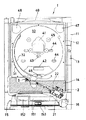
以下、本発明を図示の一実施の形態について説明する。図1は遊技機、即ちパチンコ機1の概略を示す一部を欠截した正面図である。
【0006】
パチンコ機1は、一般に窓部を有する額縁状の前枠11の一側を外枠に開閉可能に蝶着し、上記窓部にはガラスを装着したガラス飾り枠12を開閉可能に軸着し、上記前枠11及びガラス飾り枠12を施錠装置13で施錠する。また、ガラス飾り枠12の下方部分には、上受皿セット(図示せず)を設け、前枠11の下方部分には下皿151を備える下受皿セット15を設ける。上記上受皿セットの裏面側に位置するフロントプレート14には上皿から打球発射装置2へ球を一個宛に供給する球送り装置等が配置してある。一方、上記打球発射装置2はソレノイド21を駆動源として杵先22で球発射位置にある球を打ち出す。
【0007】
上記前枠11の窓部には、この窓部を塞ぐようにフロントプレート14に載せて交換可能に構成した遊技盤3を臨ませる。遊技盤3の前面側には後述する外レール31及び内レール32を配設してほゞ円形に囲まれる遊技部33を形成する。また、この遊技部33内には、可変表示装置41や変動入賞装置42等の各種役物、始動口43や一般入賞口44、風車45、或は各種表示灯等、様々な遊技部材を配設し、最下位置にアウト口46を設ける。更に、外レール31または内レール32の外側で右側の上方隅部分には完了表示灯47を、外レール31の外側で左側の上方隅部分には賞球表示灯48を設け、更にガラス飾り枠12の上部には外部表示灯49を設ける。
【0008】
上記下受皿セット15の前面側には打球発射装置2により遊技部33に向けて打ち込まれる打球の飛距離を調整するための操作グリップ16を設ける。また、この下受皿セット15には、獲得した賞球を貯留しておくための下皿151の他、灰皿152や球抜きレバー153等が設けてある。
【0009】
上記のような諸装置或いは諸部材を組み付ける前枠11は、ベニヤ合板等を切削加工して構成してもよいし、合成樹脂を成形して構成してもよい。また、前枠11をヒンジ装置により蝶着する外枠は、木板等を矩形に枠組したものでも、合成樹脂で構成したものでも、適宜に使用できる。
【0010】
遊技盤3は、パチンコ機1を構成する主要な部材であって、ベニヤ合板の前面にデザイン画が描かれた図示しないセルシートを一体に結合したほゞ方形の遊技盤本体34に種々の遊技部材を取り付けて構成する。この遊技盤本体34は、例えばベニヤ合板を切削加工して形成する。
【0011】
遊技盤本体34の前面側には、後述するベース飾り部材35を添設して打球が流下する遊技部33と装飾のための非遊技部33′とを形成する。即ち、遊技者が発射した打球が流下する部分と、打球が飛び出すことがなく、専ら表示及び装飾に用いる部分とに区画する。このため、従来の遊技盤3においては、「ガイドレール」或は「バンド」等と呼ばれる帯状のステンレス板をほゞ円形ないし渦巻状に配置すると共に、割ピンを遊技盤本体34に打ち込んで固定していた。また、上記ガイドレールの基端には円筒形の止着部を曲折し、この止着部に通した釘を遊技盤面に打ち込んで、ガイドレールの基端を固定していた。
【0012】
このため、従来のパチンコ機1にあっては、上記ガイドレールを所定の形状に、即ち正しい曲線を描くように、且つ盤面に対して直立するように、固定するのが困難であったばかりではなく、基端部分の取付角度が製品毎に微妙に異なり、打球が正しい軌道に乗らなかったり、飛距離がまちまちになっていた。
【0013】
そこで、本発明では、ガイドレールを形成する外レール31の基端に傾斜調整手段5を設けて、外レール31の基端部分における取付角度を調整可能にしている。また、図示した実施の形態では、ベース飾り部材35に設けた外レール31の基端を打球発射装置2から発射される打球の弾道の近傍に止着するための外レール固定金具6に対して上記傾斜調整手段5を設けてユニット化している。
【0014】
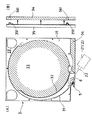
遊技盤本体34に重合させると共に、外レール31及び内レール32を沿わせて打球が流下する遊技部33と装飾のための非遊技部33′とを形成するベース飾り部材35は、遊技盤本体34とほゞ同形に構成した板状の第1ベース部材と、中央にほゞ円形の空部を備えると共に四隅に前面板部を備える第2ベース部材とから構成してある。
【0015】
上記第1ベース部材は、光透過性の合成樹脂により一体成形してあり、遊技盤本体34のデザイン画が透過して見える。また、第1ベース部材の中央部分には、遊技部33となるほゞ円形の空部を設け、遊技盤本体34の表面部分が見えるようにする。また、上記空部の周囲に設けた外レール装着部にステンレス製のバンドを装着して外レール31を形成する。
【0016】
上記外レール31の基端部分は、外レール固定金具6によって第1ベース部材に固定されるが、打球発射装置2から弾発された打球が着弾する部分の周辺は、当該外レール31の背面側が空間になると共に下縁が第1ベース部材と接触することなく自由になっている。
【0017】
そして、上記第1ベース部材及び第2ベース部材並びに外レール31は、ベース飾り部材35としてユニット化してある。また、ベース飾り部材35の裏面側の適宜位置には位置決めボス351を設け、このボス351を遊技盤本体34に設けた位置決め孔341に嵌合させて、上記ベース飾り部材35を位置決めする。
【0018】
従って、上記ベース飾り部材35を遊技盤本体34に重合して取り付ければ、遊技盤3が簡単に組み上がる。そして、本発明に係る傾斜調整手段5も前記ベース飾り部材35のユニットに組み込まれており、簡単に外レール31の傾斜角度の調整ができるようになる。
【0019】
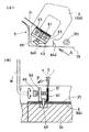
外レール固定金具6は、固定基板として機能するベース飾り部材35に、裏面側からビス等によって固定する金具であり、外レール31の基端に設けた止着部を装着する装着片61を備える。この装着片61は、図3に示す実施の形態によれば、ほゞL字型に曲折した板バネからなり、傾斜調整手段5を構成するためのL字型の支持板62と共に、前記ベース飾り部材35を挟着するようにネジ63によって取り付けてある。しかし、装着片61は、後述するように、外レール固定金具6の取付基板64を切り起こして形成してもよい。
【0020】
図3に示す傾斜調整手段5の第1の実施形態は、前記した外レール固定金具6の装着片61の近傍にL字型の支持板62を設け、この支持板62のほゞ中央に水平方向に開設したネジ孔(図示せず)に調整ネジ65を螺合し、この調整ネジ65を上記装着片61に向けてねじ込むように構成する。
【0021】
即ち、外レール固定金具6に固定した装着片61を、図3に示すように、取付基板64に対して直角な状態を基準とするとき、装着片61を予め図中矢印F方向に所望の角度だけ倒しておけば、板バネの弾性によって常にF方向に付勢されることになる。尚、以下、装着片61即ち外レール31が遊技盤面に対して直角に起立する状態を「0」、上記矢印F方向に倒れた状態を「+」、F方向と逆の方向に倒れた状態を「−」という。
【0022】
そこで、+側にある装着片61に向けて、調整ネジ65をねじ込んで行くと、やがて調整ネジ65の先端が装着片61に当接し、更にねじ込めば、装着片61が徐々に起立する。従って、所望の角度になるように調整ネジ65をねじ込んで、打球の軌道を調整する。尚、基準線である0を越えても、F方向の付勢が継続するので、調整ネジ65が緩むことがない。一方、調整ネジ65は、頭部に六角孔を有するものを使用すれば、六角レンチWによって調整ネジ65の直角方向から回すことができ、遊技盤3をパチンコ機1に取り付けた状態でも、遊技盤3の前面側から作業することができる。
【0023】
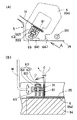
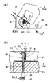
図4は、傾斜調整手段5の第2の実施形態を示す。この実施形態は上記した実施形態とほゞ同様の構成を備えるが、支持板62がベース飾り部材35に一体に形成してある。また、装着片61が外レール固定金具6の取付基板64を切り起こして形成しある。即ち、この実施形態においては、上記ベース飾り部材35に一体に突設した一対の支持部621,621の中にナット622を装着し、このナット622に傾斜調整ネジ65を螺合させている。
【0024】
一方、外レール31の基端を固定する装着片61は、外レール固定金具6の取付基板64を切り起こして形成したもので、図示していないが外レール31の基端に設けたダボが陥入する嵌着孔が開設してある。尚、取付基板64には取付ビスを通す取付孔や位置決め孔を設ける。また、取付基板64の下縁の一部にはベース飾り部材35のベース板部の下縁部分を巻くように屈曲させた屈曲係止片641が設けてあり、遊技盤3をフロントプレート14に載せて設置するときに使用する係止金具の係止リング(図示せず)が係止する。更に、取付基板64の下縁隅には、遊技盤3をフロントプレート14に設置した場合に、外レール31の基端部分との間に生じる隙間を塞ぐように立上り閉止片642を設け、この閉止片642により怪我をしないように保護キャップを被せている。
【0025】
この実施形態においても、外レール固定金具6の装着片61を予め+側へ傾斜させて付勢し、調整ネジ65をねじ込むことにより装着片61が所望の角度になるように起立させている。尚、調整ネジ65の先端が、前記したダボの裏側に生じる凹部に陥入するようにすると安定して好適である。
【0026】
図5は、傾斜調整手段5の第3の実施形態を示す。この実施形態では、外レール固定金具6から装着片61をほゞ90度に起立させると共に、装着片61の上端に係止部612を形成し、該係止部612に係止可能なネジ機構66を設けている。
【0027】
ネジ機構66は、外レール固定金具6或いはベース飾り部材35に取り付けた支持部材661に、頭部651が前記装着片61の係止部612に係止可能なように調整ネジ65を螺合してなる。尚、この調整ネジ65の先端にはドライバー等の工具が嵌入する係合溝652が設けてある。
【0028】
この実施形態による傾斜調整手段5によって、外レール31の取付角度を調整するには、装着片61の起立角度である90度前後において、調整ネジ65の係合溝652にドライバー或いは専用のツマミHを係合させて、当該調整ネジ65を回動させる。すると、調整ネジ65の頭部651が係止部612に係合して装着片61を引き付けるため、外レール31が+側に傾く。一方、上記調整ネジ65を反対方向に回動させれば、当該調整ネジ65の頭部651が装着片61を押圧して−側に傾斜させる。尚、調整量が少ない場合には、調整ネジ65が緩む可能性があるので、接着剤等を利用して回り止処置を講じるとよい。
【0029】
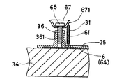
図6は、傾斜調整手段5の第4の実施形態を示す。この実施形態では、テーパー付きワッシャ67を用いて外レール31の起立角度を調整している。即ち、外レール固定金具6の装着片61の近傍に位置するように、ベース飾り部材35から上下方向のネジ孔361を有するボス部36を突設し、上記ネジ孔361にテーパー付きワッシャ67を介して調整ネジ65を螺合して、テーパー面671が装着片61の先端に当接するように構成している。
【0030】
例えば、装着片61が90度に起立した0のときに、装着片61の先端がテーペー面671の中間に当接するように設定し、調整ネジ65を締め込んで行けば−側に傾斜し、緩めれば+側に傾斜するので、外レール31の取付角度を容易に調整できる。尚、装着片61は他の実施形態と同様に予め+側に付勢してある。
【0031】
図7は第5の実施形態を示し、この実施形態では、傾斜プレート68を用いている。即ち、ベース飾り部材35に、上下方向のネジ孔371を有する支持ボス37を設けると共に、ガイド溝381を有するガイドボス38を突設する。そして、一端に傾斜面681を有すると共に、他端にガイド片682を有する傾斜プレート68を、調整ネジ65によって前記ネジ孔371に螺合する。
【0032】
この実施形態においても、装着片61を予め+側に付勢しておき、傾斜面681に装着片61の先端を当接させると共に、ガイド片682をガイド溝381に嵌入させる。調整ネジ65をねじ込めば、傾斜プレート68が下降して装着片61を押圧するので、装着片61が−側に倒れ、調整ネジ65を緩めれば傾斜プレート68が上昇するので、装着片61が復帰して+側に倒れる。
【0033】
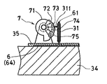
図8は第6の実施形態を示し、この実施形態では、中心からの距離の異なる複数の係止面71,72,…を有するカタツムリ状の調整カム7を用いている。即ち、係止面71,72,…に、外レール31の折り返し部分を切り起こして形成した係止片311を係止させて、装着片61を押圧することにより、外レール31の取付角度を調整している。
【0034】
例えば、5段階の係止面71,72,73,74,75を形成した調整カム7を適用し、中心からの距離が短い係止面71,72と係止するときは+側に傾き、中心からの距離が長い係止面74,75に係止するときは−側に傾いて、外レール31の取付角度を5段階に調整する。
【0035】
図9は第7の実施形態を示し、この実施形態では、頭部の径の異なる複数の調整ネジ81,82,83,84,85によって形成した調整駒8を交換することにより外レール31の取付角度を調整している。即ち、ベース飾り部材35に突設した支持ボス37に、頭部の径の異なる調整ネジ81,82,…を螺合し、この調整ネジ81,82,…の頭部によって装着片61を押圧している。例えば、5種類の調整ネジ81,82,83,84,85を用意し、中間の大きさの頭部を有する3番の調整ネジ83を用いたときに外レール31が90度に起立して0となるように設定し、+側に傾斜させたいときは、小径の1番または2番の調整ネジ81,82を用い、−側に傾斜させるときは大径の4番または5番の調整ネジ84,85を用いる。
【0036】
図10は第8の実施形態を示し、この実施形態は、偏心した頭部91を有する偏心ネジ9を用いたものである。即ち、ネジ部92の中心に対して偏心した位置に頭部91を有する偏心ネジ9を、装着片61の近傍に位置するように遊技盤本体34に締め込んでおき、この遊技盤本体34に、ベース飾り部材35を装着する。そして、偏心ネジ9の頭部91を外レール31の装着部分に延設した延設片312のカム孔313に挿通し、該カム孔313と偏心ネジ9の頭部91とを係止させる。そして、ドライバー等の工具を係合させるために頭部91に設けたすり割93の向きが外レール31とほゞ平行するときに、外レール31がほゞ90度に起立するように設定し、偏心ネジ9を図10に矢印Rで示した囲内で回動させて、偏心した頭部91とカム孔313との係止位置によって外レール31を−側及び+側に傾斜させる。
【0037】
上記したような各実施の形態による傾斜調整手段5によれば、何れの形態でも熟練技術を要することなく外レール31の取付角度を容易に調整することができる。そして、外レール31の取付角度が正確に調整されると、打球が通路の中央を通り、ガラスに衝突したり、遊技盤面に衝突することがなくなり球飛びが安定する。
【0038】
以上本発明を図面の実施形態について説明したが、本発明は上記した各実施形態に限定されるものではなく、特許請求の範囲に記載した構成を変更しない限り適宜に実施できる。
【0039】
【発明の効果】
以上要するに本発明は、遊技盤本体に外レール及び内レールを立設して、打球が流下する遊技部と該遊技部の外側に位置する非遊技部とを区画形成し、遊技機に交換自在に装着する遊技盤であって、打球を遊技部に誘導するように外レールをほゞ円弧状に配設し、打球発射装置から発射された打球が着弾する着弾点付近の外レールの背面側に空間を形成すると共に、着弾点付近の外レールの遊技盤面に対する起立角度を調整する傾斜調整手段を設け、前記外レールの基端を、打球発射装置から発射される打球の弾道の近傍に、遊技盤に固定した弾性を有する装着片により止着し、前記傾斜調整手段は、遊技盤面から起立するように設けられて、ネジ孔を有する支持ボスと、この支持ボスのネジ孔に螺合して遊技盤に向って操作する頭部の径が異なる複数種類の調整ネジと、を備え、前記複数種類の調整ネジから一つを選択して前記支持ボスに螺合させて、前記調整ネジの頭部で前記装着片を押圧することにより、外レールの取付角度を調整し、打球の軌道を修正可能とした。
このため、外レールの取付角度を容易に調整でき、打球が遊技盤面に衝突したり、ガラスに衝突したりすることのない正しい軌道へ打球を導くことができる。また、外レールと傾斜調整手段との位置関係が正確に保たれるので、傾斜調整手段が充分に機能する。更に、傾斜調整手段を含めたユニット化が可能であり、ユニットの位置決めが正確であるので、品質の均一な遊技盤を提供する。
【図面の簡単な説明】
【図1】パチンコ機の概略を示す一部を欠截した正面図である。
【図2】遊技盤の概略を示し、(A)は正面図、(B)は分解した側面図である。
【図3】傾斜調整手段の実施形態を示し、(A)は平面図、(B)は矢視Aにおける断面図である。
【図4】傾斜調整手段の他の実施形態を示し、(A)は平面図、(B)は矢視Aにおける断面図である。
【図5】傾斜調整手段の他の実施形態を示し、(A)は平面図、(B)は矢視Aにおける断面図である。
【図6】傾斜調整手段の他の実施形態を示す断面図である。
【図7】傾斜調整手段の他の実施形態を示す断面図である。
【図8】傾斜調整手段の他の実施形態を示す断面図である。
【図9】傾斜調整手段の他の実施形態を示す断面図である。
【図10】傾斜調整手段の他の実施形態を示し、(A)は平面図、(B)は矢視Aにおける断面図である。
【符号の説明】
1 パチンコ機
2 打球発射装置
3 遊技盤
5 傾斜調整手段
6 外レール固定金具
7 調整カム
8 調整駒
9 偏心ネジ
31 外レール
34 遊技盤本体
35 ベース飾り部材
61 装着片
65 調整ネジ
66 ネジ機構
67 テーパー付きワッシャ
68 傾斜プレート[0001]
BACKGROUND OF THE INVENTION
The present invention relates to a game board of a gaming machine, and in particular, in a game board of a so-called separation type game machine that can be replaced by removing only the game board from the main body of the gaming machine, the gaming board of the gaming machine that can obtain stable hitting. It is about.
[0002]
[Prior art]
In the game board of the gaming machine, the hit ball fired from the hit ball launching device jumps over the foul ball from the launch rail to land on the outer rail, and is led to the outer rail and jumps into the game section. The conventional outer rail generally forms a cylindrical fixing portion through which the fixed nail passes by bending the base end portion, and the fixed nail passed through the fixing portion is driven into a game board body made of veneer plywood. It was fixed. Further, the conventional outer rail has been fixed by driving cotter pins locked to the lower edge at appropriate intervals into the game board main body.
On the other hand, in order to guide the hit ball to the game unit without colliding with the glass surface or the game board surface, the fixed outer rail must be erected at a predetermined angle with respect to the game board main body. Therefore, conventionally, the mounting angle of the outer rail has been adjusted by hitting the above-described fixing nail with a hammer or the like from the side.
[0003]
[Problems to be solved by the invention]
The mounting angle of the outer rail, that is, the standing state of the outer rail with respect to the game board surface, has a slight effect on the hitting of the hit ball, and must be adjusted to a predetermined angle.
However, since this adjustment is performed by hitting the fixed nail with a hammer or the like as described above, it requires skill. In addition, since this adjustment work must be performed in a narrow work space, other members and the assembly machine may be accidentally hit to make the game board unusable or damage the assembly machine.
The present invention has been proposed in view of the above, and an object of the present invention is to provide a game board that can easily adjust the mounting angle of the outer rail that guides the hit ball to the game part.
[0004]
[Means for Solving the Problems]
In order to achieve the above object, the present invention provides an outer rail and an inner rail standing on the game board main body to partition and form a game part where a hit ball flows down and a non-game part located outside the game part. A game board that is exchangeably mounted on the machine, and the outer rail is arranged in a generally arc shape so as to guide the hit ball to the game part, and the outside of the vicinity of the landing point where the hit ball emitted from the hit ball launching device lands. In addition to forming a space on the back side of the rail and providing an inclination adjusting means for adjusting the standing angle of the outer rail near the landing point with respect to the game board surface, the trajectory of the hit ball launched from the hit ball launcher is used as the base end of the outer rail. The inclination adjusting means is provided so as to stand up from the game board surface, and is attached to a support boss having a screw hole, and a screw hole of the support boss. And screw it into the game board A plurality of types of adjustment screws having different diameters, and one of the plurality of types of adjustment screws is selected and screwed into the support boss, and the mounting piece is pressed by the head of the adjustment screw. Thus, the mounting angle of the outer rail can be adjusted, and the trajectory of the hit ball can be corrected.
[0005]
DETAILED DESCRIPTION OF THE INVENTION
The present invention will be described below with reference to an embodiment shown in the drawings. FIG. 1 is a front view of a gaming machine, that is, a part of the outline showing a
[0006]
The
[0007]
A
[0008]
On the front side of the lower tray set 15, an
[0009]
The
[0010]
The
[0011]
On the front side of the game board
[0012]
For this reason, in the
[0013]
Therefore, in the present invention, the inclination adjusting means 5 is provided at the base end of the
[0014]
A
[0015]
The first base member is integrally formed of a light-transmitting synthetic resin, and the design image of the game board
[0016]
The base end portion of the
[0017]
The first base member, the second base member, and the
[0018]
Accordingly, if the
[0019]
The outer
[0020]
In the first embodiment of the inclination adjusting means 5 shown in FIG. 3, an L-shaped
[0021]
That is, when the mounting
[0022]
Therefore, when the
[0023]
FIG. 4 shows a second embodiment of the inclination adjusting means 5. This embodiment has substantially the same configuration as the above-described embodiment, but the
[0024]
On the other hand, the mounting
[0025]
Also in this embodiment, the mounting
[0026]
FIG. 5 shows a third embodiment of the inclination adjusting means 5. In this embodiment, the mounting
[0027]
The
[0028]
In order to adjust the mounting angle of the
[0029]
FIG. 6 shows a fourth embodiment of the inclination adjusting means 5. In this embodiment, the standing angle of the
[0030]
For example, when the mounting
[0031]
FIG. 7 shows a fifth embodiment, in which an
[0032]
Also in this embodiment, the mounting
[0033]
FIG. 8 shows a sixth embodiment. In this embodiment, a snail-shaped adjustment cam 7 having a plurality of locking
[0034]
For example, when the adjustment cam 7 formed with five stages of the locking surfaces 71, 72, 73, 74, 75 is applied, and when locking with the locking surfaces 71, 72 having a short distance from the center, it is inclined to the + side, When locking to the locking surfaces 74 and 75 having a long distance from the center, the mounting angle of the
[0035]
FIG. 9 shows a seventh embodiment. In this embodiment, the
[0036]
FIG. 10 shows an eighth embodiment, which uses an
[0037]
According to the inclination adjusting means 5 according to each embodiment as described above, the mounting angle of the
[0038]
Although the present invention has been described with reference to the embodiments of the drawings, the present invention is not limited to the above-described embodiments, and can be appropriately implemented without changing the configuration described in the claims.
[0039]
【The invention's effect】
In short, the present invention is such that the outer rail and the inner rail are erected on the game board main body, and the game portion where the hit ball flows down and the non-game portion located outside the game portion are partitioned, and can be exchanged for a gaming machine. The outer rail is arranged in a generally arc shape so as to guide the hit ball to the game part, and the back side of the outer rail near the landing point where the hit ball fired from the hit ball launching device lands In addition, a slope adjusting means for adjusting the standing angle of the outer rail near the landing point with respect to the game board surface is provided, and the base end of the outer rail is disposed in the vicinity of the trajectory of the hit ball launched from the hit ball launching device. The inclination adjusting means is provided so as to stand up from the game board surface, and is fixed to the game board with elastic mounting pieces. The support boss has a screw hole and is screwed into the screw hole of the support boss. The diameter of the head that is operated toward the game board A plurality of types of adjustment screws, and selecting one of the plurality of types of adjustment screws to be screwed onto the support boss and pressing the mounting piece with the head of the adjustment screw, The rail mounting angle can be adjusted to correct the ball trajectory.
For this reason, the mounting angle of the outer rail can be easily adjusted, and the hit ball can be guided to the correct trajectory where the hit ball does not collide with the game board surface or the glass. In addition, since the positional relationship between the outer rail and the inclination adjusting means is accurately maintained, the inclination adjusting means functions sufficiently. Furthermore, since a unit including an inclination adjusting means can be formed and the positioning of the unit is accurate, a game board with uniform quality is provided.
[Brief description of the drawings]
FIG. 1 is a front view of a part of the outline showing a pachinko machine.
FIG. 2 shows an outline of a game board, (A) is a front view, and (B) is an exploded side view.
3A and 3B show an embodiment of the tilt adjusting means, in which FIG. 3A is a plan view, and FIG.
4A and 4B show another embodiment of the tilt adjusting means, in which FIG. 4A is a plan view, and FIG. 4B is a cross-sectional view taken along arrow A. FIG.
5A and 5B show another embodiment of the tilt adjusting means, wherein FIG. 5A is a plan view, and FIG. 5B is a cross-sectional view taken along arrow A. FIG.
FIG. 6 is a cross-sectional view showing another embodiment of the inclination adjusting means.
FIG. 7 is a cross-sectional view showing another embodiment of the inclination adjusting means.
FIG. 8 is a cross-sectional view showing another embodiment of the tilt adjusting means.
FIG. 9 is a cross-sectional view showing another embodiment of the tilt adjusting means.
10A and 10B show another embodiment of the tilt adjusting means, where FIG. 10A is a plan view and FIG. 10B is a cross-sectional view taken along arrow A. FIG.
[Explanation of symbols]
DESCRIPTION OF
Claims (1)
打球を遊技部に誘導するように外レールをほゞ円弧状に配設し、打球発射装置から発射された打球が着弾する着弾点付近の外レールの背面側に空間を形成すると共に、着弾点付近の外レールの遊技盤面に対する起立角度を調整する傾斜調整手段を設け、
前記外レールの基端を、打球発射装置から発射される打球の弾道の近傍に、遊技盤に固定した弾性を有する装着片により止着し、
前記傾斜調整手段は、遊技盤面から起立するように設けられて、ネジ孔を有する支持ボスと、この支持ボスのネジ孔に螺合して遊技盤に向って操作する頭部の径が異なる複数種類の調整ネジと、を備え、
前記複数種類の調整ネジから一つを選択して前記支持ボスに螺合させて、前記調整ネジの頭部で前記装着片を押圧することにより、外レールの取付角度を調整し、打球の軌道を修正可能としたことを特徴とする遊技機の遊技盤。A game board in which an outer rail and an inner rail are erected on the game board main body, and a game part where a hit ball flows down and a non-game part located outside the game part are partitioned, and are exchangeably mounted on a game machine. There,
The outer rail is arranged in a generally arc shape so as to guide the hit ball to the game part, and a space is formed on the back side of the outer rail near the landing point where the hit ball launched from the hit ball launching device lands, and the landing point Inclination adjustment means to adjust the standing angle of the nearby outer rail with respect to the game board surface,
The base end of the outer rail is fixed in the vicinity of the trajectory of the hit ball launched from the hit ball launching device by an elastic mounting piece fixed to the game board,
The inclination adjusting means is provided so as to stand up from the game board surface, and has a plurality of support bosses having screw holes and different head diameters that are screwed into the screw holes of the support bosses and operated toward the game board. With different types of adjustment screws,
One of the plurality of types of adjustment screws is selected and screwed into the support boss, and the mounting piece is pressed with the head of the adjustment screw to adjust the mounting angle of the outer rail, and the ball trajectory A game board of a gaming machine characterized in that it can be modified.
Priority Applications (1)
| Application Number | Priority Date | Filing Date | Title |
|---|---|---|---|
| JP35989597A JP4100478B2 (en) | 1997-12-26 | 1997-12-26 | Game machine game board |
Applications Claiming Priority (1)
| Application Number | Priority Date | Filing Date | Title |
|---|---|---|---|
| JP35989597A JP4100478B2 (en) | 1997-12-26 | 1997-12-26 | Game machine game board |
Publications (2)
| Publication Number | Publication Date |
|---|---|
| JPH11188143A JPH11188143A (en) | 1999-07-13 |
| JP4100478B2 true JP4100478B2 (en) | 2008-06-11 |
Family
ID=18466846
Family Applications (1)
| Application Number | Title | Priority Date | Filing Date |
|---|---|---|---|
| JP35989597A Expired - Fee Related JP4100478B2 (en) | 1997-12-26 | 1997-12-26 | Game machine game board |
Country Status (1)
| Country | Link |
|---|---|
| JP (1) | JP4100478B2 (en) |
Families Citing this family (8)
| Publication number | Priority date | Publication date | Assignee | Title |
|---|---|---|---|---|
| JP2006271639A (en) * | 2005-03-29 | 2006-10-12 | Juki Corp | Rail adjustment mechanism |
| JP4842556B2 (en) * | 2005-04-18 | 2011-12-21 | 株式会社浅間製作所 | Game machine bullet launcher |
| JP2007307055A (en) * | 2006-05-17 | 2007-11-29 | Olympia:Kk | Pachinko machine |
| JP5076397B2 (en) * | 2006-08-11 | 2012-11-21 | 株式会社三洋物産 | Game machine |
| JP4783332B2 (en) * | 2007-06-12 | 2011-09-28 | 株式会社ソフイア | Game machine |
| JP5601457B2 (en) * | 2010-06-24 | 2014-10-08 | 株式会社三洋物産 | Game machine |
| JP2014230986A (en) * | 2014-08-22 | 2014-12-11 | 株式会社三洋物産 | Game machine |
| CN113187813B (en) * | 2021-04-13 | 2023-02-03 | 西安理工大学 | Radial positioning mechanism of arc rolling guide rail |
-
1997
- 1997-12-26 JP JP35989597A patent/JP4100478B2/en not_active Expired - Fee Related
Also Published As
| Publication number | Publication date |
|---|---|
| JPH11188143A (en) | 1999-07-13 |
Similar Documents
| Publication | Publication Date | Title |
|---|---|---|
| JP4100478B2 (en) | Game machine game board | |
| JP2006247106A (en) | Pinball game machine | |
| US7147566B2 (en) | Cue sports training device | |
| JP3862181B2 (en) | Game machine game board | |
| JP4797655B2 (en) | Game machine | |
| US5707297A (en) | Practice device for golfers | |
| JP4474123B2 (en) | Mechanism for adjusting the launch angle of a ball game machine | |
| JP4180465B2 (en) | Launch assist mechanism for ball game machines | |
| JP2003310973A (en) | Frame base body of pachinko game machine | |
| GB2184221A (en) | Cue ball aiming methods and apparatus | |
| JP4474131B2 (en) | Launch angle adjustment mechanism for ball game machines | |
| JP3739315B2 (en) | Bullet ball machine | |
| JP3147207U (en) | Gaming machine nail angle measurement gauge | |
| JP4111882B2 (en) | Launch angle adjustment mechanism of bullet ball game machine | |
| JP2002219252A (en) | Pachinko game machine | |
| JP2004201989A (en) | Pachinko game machine | |
| JP3363898B2 (en) | Ball game machine | |
| JP2003181079A (en) | Front frame of pachinko game machine | |
| JPH0898920A (en) | Game ball shooting device of pinball game machine | |
| JP4116501B2 (en) | Launch angle adjustment mechanism of bullet ball game machine | |
| JP2657359B2 (en) | Shooting rail of a ball-and-ball game machine | |
| JP4475612B2 (en) | Bullet ball machine | |
| JPH0530455Y2 (en) | ||
| JPH08252369A (en) | Pachinko game machine | |
| JP4275025B2 (en) | Vertical gaming machine |
Legal Events
| Date | Code | Title | Description |
|---|---|---|---|
| A621 | Written request for application examination |
Free format text: JAPANESE INTERMEDIATE CODE: A621 Effective date: 20040929 |
|
| A977 | Report on retrieval |
Free format text: JAPANESE INTERMEDIATE CODE: A971007 Effective date: 20070510 |
|
| A131 | Notification of reasons for refusal |
Free format text: JAPANESE INTERMEDIATE CODE: A131 Effective date: 20070605 |
|
| A521 | Written amendment |
Free format text: JAPANESE INTERMEDIATE CODE: A523 Effective date: 20070731 |
|
| A131 | Notification of reasons for refusal |
Free format text: JAPANESE INTERMEDIATE CODE: A131 Effective date: 20071106 |
|
| A521 | Written amendment |
Free format text: JAPANESE INTERMEDIATE CODE: A523 Effective date: 20071127 |
|
| TRDD | Decision of grant or rejection written | ||
| A01 | Written decision to grant a patent or to grant a registration (utility model) |
Free format text: JAPANESE INTERMEDIATE CODE: A01 Effective date: 20080219 |
|
| A61 | First payment of annual fees (during grant procedure) |
Free format text: JAPANESE INTERMEDIATE CODE: A61 Effective date: 20080312 |
|
| FPAY | Renewal fee payment (event date is renewal date of database) |
Free format text: PAYMENT UNTIL: 20110328 Year of fee payment: 3 |
|
| R150 | Certificate of patent or registration of utility model |
Free format text: JAPANESE INTERMEDIATE CODE: R150 |
|
| FPAY | Renewal fee payment (event date is renewal date of database) |
Free format text: PAYMENT UNTIL: 20110328 Year of fee payment: 3 |
|
| FPAY | Renewal fee payment (event date is renewal date of database) |
Free format text: PAYMENT UNTIL: 20120328 Year of fee payment: 4 |
|
| FPAY | Renewal fee payment (event date is renewal date of database) |
Free format text: PAYMENT UNTIL: 20130328 Year of fee payment: 5 |
|
| FPAY | Renewal fee payment (event date is renewal date of database) |
Free format text: PAYMENT UNTIL: 20130328 Year of fee payment: 5 |
|
| FPAY | Renewal fee payment (event date is renewal date of database) |
Free format text: PAYMENT UNTIL: 20140328 Year of fee payment: 6 |
|
| R250 | Receipt of annual fees |
Free format text: JAPANESE INTERMEDIATE CODE: R250 |
|
| R250 | Receipt of annual fees |
Free format text: JAPANESE INTERMEDIATE CODE: R250 |
|
| R250 | Receipt of annual fees |
Free format text: JAPANESE INTERMEDIATE CODE: R250 |
|
| LAPS | Cancellation because of no payment of annual fees |