JP4100128B2 - Telescopic shaft for vehicle steering - Google Patents
Telescopic shaft for vehicle steering Download PDFInfo
- Publication number
- JP4100128B2 JP4100128B2 JP2002309879A JP2002309879A JP4100128B2 JP 4100128 B2 JP4100128 B2 JP 4100128B2 JP 2002309879 A JP2002309879 A JP 2002309879A JP 2002309879 A JP2002309879 A JP 2002309879A JP 4100128 B2 JP4100128 B2 JP 4100128B2
- Authority
- JP
- Japan
- Prior art keywords
- shaft
- female
- peripheral surface
- torque
- male
- Prior art date
- Legal status (The legal status is an assumption and is not a legal conclusion. Google has not performed a legal analysis and makes no representation as to the accuracy of the status listed.)
- Expired - Fee Related
Links
Images


Classifications
-
- F—MECHANICAL ENGINEERING; LIGHTING; HEATING; WEAPONS; BLASTING
- F16—ENGINEERING ELEMENTS AND UNITS; GENERAL MEASURES FOR PRODUCING AND MAINTAINING EFFECTIVE FUNCTIONING OF MACHINES OR INSTALLATIONS; THERMAL INSULATION IN GENERAL
- F16C—SHAFTS; FLEXIBLE SHAFTS; ELEMENTS OR CRANKSHAFT MECHANISMS; ROTARY BODIES OTHER THAN GEARING ELEMENTS; BEARINGS
- F16C3/00—Shafts; Axles; Cranks; Eccentrics
- F16C3/02—Shafts; Axles
- F16C3/03—Shafts; Axles telescopic
- F16C3/035—Shafts; Axles telescopic with built-in bearings
-
- F—MECHANICAL ENGINEERING; LIGHTING; HEATING; WEAPONS; BLASTING
- F16—ENGINEERING ELEMENTS AND UNITS; GENERAL MEASURES FOR PRODUCING AND MAINTAINING EFFECTIVE FUNCTIONING OF MACHINES OR INSTALLATIONS; THERMAL INSULATION IN GENERAL
- F16C—SHAFTS; FLEXIBLE SHAFTS; ELEMENTS OR CRANKSHAFT MECHANISMS; ROTARY BODIES OTHER THAN GEARING ELEMENTS; BEARINGS
- F16C29/00—Bearings for parts moving only linearly
- F16C29/007—Hybrid linear bearings, i.e. including more than one bearing type, e.g. sliding contact bearings as well as rolling contact bearings
-
- F—MECHANICAL ENGINEERING; LIGHTING; HEATING; WEAPONS; BLASTING
- F16—ENGINEERING ELEMENTS AND UNITS; GENERAL MEASURES FOR PRODUCING AND MAINTAINING EFFECTIVE FUNCTIONING OF MACHINES OR INSTALLATIONS; THERMAL INSULATION IN GENERAL
- F16C—SHAFTS; FLEXIBLE SHAFTS; ELEMENTS OR CRANKSHAFT MECHANISMS; ROTARY BODIES OTHER THAN GEARING ELEMENTS; BEARINGS
- F16C29/00—Bearings for parts moving only linearly
- F16C29/12—Arrangements for adjusting play
- F16C29/123—Arrangements for adjusting play using elastic means
-
- F—MECHANICAL ENGINEERING; LIGHTING; HEATING; WEAPONS; BLASTING
- F16—ENGINEERING ELEMENTS AND UNITS; GENERAL MEASURES FOR PRODUCING AND MAINTAINING EFFECTIVE FUNCTIONING OF MACHINES OR INSTALLATIONS; THERMAL INSULATION IN GENERAL
- F16C—SHAFTS; FLEXIBLE SHAFTS; ELEMENTS OR CRANKSHAFT MECHANISMS; ROTARY BODIES OTHER THAN GEARING ELEMENTS; BEARINGS
- F16C2326/00—Articles relating to transporting
- F16C2326/20—Land vehicles
- F16C2326/24—Steering systems, e.g. steering rods or columns
-
- F—MECHANICAL ENGINEERING; LIGHTING; HEATING; WEAPONS; BLASTING
- F16—ENGINEERING ELEMENTS AND UNITS; GENERAL MEASURES FOR PRODUCING AND MAINTAINING EFFECTIVE FUNCTIONING OF MACHINES OR INSTALLATIONS; THERMAL INSULATION IN GENERAL
- F16C—SHAFTS; FLEXIBLE SHAFTS; ELEMENTS OR CRANKSHAFT MECHANISMS; ROTARY BODIES OTHER THAN GEARING ELEMENTS; BEARINGS
- F16C29/00—Bearings for parts moving only linearly
- F16C29/04—Ball or roller bearings
-
- F—MECHANICAL ENGINEERING; LIGHTING; HEATING; WEAPONS; BLASTING
- F16—ENGINEERING ELEMENTS AND UNITS; GENERAL MEASURES FOR PRODUCING AND MAINTAINING EFFECTIVE FUNCTIONING OF MACHINES OR INSTALLATIONS; THERMAL INSULATION IN GENERAL
- F16C—SHAFTS; FLEXIBLE SHAFTS; ELEMENTS OR CRANKSHAFT MECHANISMS; ROTARY BODIES OTHER THAN GEARING ELEMENTS; BEARINGS
- F16C33/00—Parts of bearings; Special methods for making bearings or parts thereof
- F16C33/30—Parts of ball or roller bearings
- F16C33/58—Raceways; Race rings
- F16C33/60—Raceways; Race rings divided or split, e.g. comprising two juxtaposed rings
Description
【0001】
【発明の属する技術分野】
本発明は、安定した摺動荷重を実現すると共に、ガタ付きを確実に防止して、高剛性の状態でトルクを伝達できる車両ステアリング用伸縮軸に関する。
【0002】
【従来の技術】
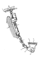
図14に、一般的な自動車の操舵機構部を示す。図中のaとbが伸縮軸である。伸縮軸aは、雄軸と雌軸とをスプライン嵌合したものであるが、このような伸縮軸aには自動車が走行する際に発生する軸方向の変位を吸収し、ステアリングホイール上にその変位や振動を伝えない性能が要求される。このような性能は、車体がサブフレーム構造となっていて、操舵機構上部を固定する部位cとステアリングラックdが固定されているフレームeが別体となっておりその間がゴムなどの弾性体fを介して締結固定されている構造の場合に要求されることが一般的である。また、その他のケースとして操舵軸継手gをピニオンシャフトhに締結する際に作業者が、伸縮軸をいったん縮めてからピニオンシャフトhに嵌合させ締結させるため伸縮機能が必要とされる場合がある。さらに、操舵機構の上部にある伸縮軸bも、雄軸と雌軸とをスプライン嵌合したものであるが、このような伸縮軸bには、運転者が自動車を運転するのに最適なポジションを得るためにステアリングホイールiの位置を軸方向に移動し、その位置を調整する機能が要求されるため、軸方向に伸縮する機能が要求される。前述のすべての場合において、伸縮軸にはスプライン部のガタ音を低減することと、ステアリングホイール上のガタ感を低減することと、軸方向摺動動作時における摺動抵抗を低減することが要求される。
【0003】
このようなことから、特許文献1では、雄軸の外周面と雌軸の内周面に形成した複数組の軸方向溝の間に、複数組のトルク伝達部材(円柱体)が嵌合してある。
【0004】
各組のトルク伝達部材(円柱体)は、軸方向に並列した複数個のニードルローラからなっている。
【0005】
これにより、トルク非伝達時(摺動時)には、雄軸と雌軸の間のガタ付きを防止することができ、雄軸と雌軸は、ガタ付きのない安定した摺動荷重で軸方向に摺動することができる。また、トルク伝達時には、雄軸と雌軸は、その回転方向のガタ付きを防止して、高剛性の状態でトルクを伝達することができる。
【0006】
さらに、ニードルローラの回転方向(周方向)のガタ付きを防止するため、樹脂製の調整部材(保持器)が設けてある。
【0007】
【特許文献1】
欧州特許出願公開EP1078843A1号公報
【0008】
【発明が解決しようとする課題】
上述した特許文献1では、ステアリング用シャフトに求められる、ニードルローラの回転方向(周方向)のガタ付きを防止するため、樹脂製の調整部材(保持器)が設けてある。この樹脂製の調整部材(保持器)により、雄軸、雌軸、ニードルローラ間における微小な隙間を調整することができる。
【0009】
しかしながら、樹脂製の調整部材(保持器)では、耐摩耗性に問題があり、長期間にわたってガタつきのない性能を維持することが困難である。そのため、摩耗が生じると、ステアリングシャフトにガタ付きを感じるといったことがある。
【0010】
また、上記特許文献1の伸縮軸は、テレスコピック用として使われるので、軸方向に相対移動をすることが求められ、雄軸・雌軸間で相対移動をするからには、摺動部には隙間を持たざるを得ないという構造上の問題点を抱えている。
【0011】
本発明は、上述したような事情に鑑みてなされたものであって、安定した摺動荷重を実現すると共に、回転方向ガタ付きを確実に防止して、高剛性の状態でトルクを伝達でき、しかも、コンパクト化を図りつつ、部品点数を削減し、組立作業を容易して製造コストを低減することができる車両ステアリング用伸縮軸を提供することを目的とする。
【0012】
【課題を解決するための手段】
上記の目的を達成するため、本発明の請求項1に係る車両ステアリング用伸縮軸は、車両のステアリングシャフトに組込み、雄軸と雌軸をトルク伝達可能に且つ軸方向に相対移動可能に嵌合した車両ステアリング用伸縮軸において、
前記雄軸の外周面と前記雌軸の内周面とに設けられた第1介装部と、該第1介装部に配置され前記雄軸と前記雌軸との軸方向相対移動の際には前記雌軸に対して摺動する円柱体からなる第1トルク伝達部材と、前記第1介装部において前記第1トルク伝達部材と前記雄軸との間に前記第1トルク伝達部材に隣接して配置され、回転の際には前記第1トルク伝達部材を拘束し、非回転の際には前記雌軸に対して前記第1トルク伝達部材を予圧する板バネと、からなる第1のトルク伝達装置と、
前記雄軸の外周面に前記第1のトルク伝達装置と周方向に所定の間隔で形成された軸方向溝と該軸方向溝に対向して前記雌軸の内周面に形成された軸方向溝とで構成された第2介装部と、該第2介装部に配置され前記雄軸と前記雌軸との軸方向相対移動の際には前記雌軸に形成された前記軸方向溝に対して摺動し、回転の際には前記雄軸に形成された前記軸方向溝および前記雌軸に形成された前記軸方向溝に接触してトルクを伝達する円柱体からなる第2トルク伝達部材とからなる第2のトルク伝達装置と、を具備することを特徴とする。
【0013】
このように、本発明の請求項1によれば、トルク非伝達時(軸方向相対移動時)には、弾性体により、第1及び第2トルク伝達部材を雌軸に対してガタ付きのない程度に径方向及び周方向に予圧しているため、雄軸と雌軸の間のガタ付きを確実に防止することができると共に、雄軸と雌軸は、ガタ付きのない安定した摺動荷重で軸方向に摺動することができる。
【0014】
トルク伝達時、弾性体により、第1及び第2トルク伝達部材を周方向に拘束できるようになっているため、雄軸と雌軸の間の回転方向ガタ付きを確実に防止して、高剛性の状態でトルクを伝達することができる。
【0016】
このように、請求項1によれば、第1及び第2トルク伝達部材は、夫々、円柱体からなり、トルク非伝達時(軸方向相対移動時)には、弾性体により、円柱体を雌軸に対してガタ付きのない程度に径方向及び周方向に予圧しているため、雄軸と雌軸との間のガタ付きを確実に防止することができると共に、雄軸と雌軸は、ガタ付きのない安定した摺動荷重で軸方向に摺動することができる。また、トルク伝達時、弾性体により、円柱体を周方向に拘束できるようになっているため、雄軸と雌軸の間の回転方向ガタ付きを確実に防止して、高剛性の状態でトルクを伝達することができる。
【0017】
さらに、請求項2に係る車両ステアリング用伸縮軸は、前記円柱体の表面には、低摩擦の固体潤滑皮膜が形成してあることを特徴とする。
【0018】
このように、請求項2によれば、更に摺動荷重を低くしたい場合は、第1及び第2トルク伝達部材である円柱体(ニードルローラ)の表面に、固体潤滑皮膜を形成する。摺動荷重は、摩擦係数に負荷された荷重を乗じたものであるため、摩擦係数を低くすることができれば摺動荷重を低くすることができる。よって、固体潤滑皮膜を形成して、摩擦係数を小さくすることで更なる低摺動荷重を実現することができる。
【0019】
さらに、請求項3に係る車両ステアリング用伸縮軸は、雌軸の内周面には、低摩擦の固体潤滑皮膜が形成してあることを特徴とする
このように、請求項3によれば、雌軸の内周面に、固体潤滑皮膜を形成して、摩擦係数を小さくすることで更なる低摺動荷重を実現することができる。
【0020】
さらに、請求項4に係る車両ステアリング用伸縮軸は、車両のステアリングシャフトに組込み、雄軸と雌軸をトルク伝達可能に且つ相対移動可能に嵌合した車両ステアリング用伸縮軸において、
前記雄軸の外周面と前記雌軸の内周面とに設けられた介装部と、該介装部に配置され前記雄軸と前記雌軸との軸方向相対移動の際には摺動する円柱体からなるトルク伝達部材と、前記介装部において前記トルク伝達部材と前記雄軸との間に前記トルク伝達部材に隣接して配置され、回転の際には前記トルク伝達部材を拘束し、非回転の際には前記雌軸に対して前記トルク伝達部材を予圧する板バネと、からなる第1のトルク伝達装置と、
前記雌軸の内周面と前記雄軸の外周面との一方に形成した軸方向溝と、該軸方向溝に嵌合するように、前記雄軸の外周面と前記雌軸の内周面との他方に形成し、前記雄軸と前記雌軸との軸方向相対移動の際には摺動し、回転の際にはトルクを伝達する軸方向突条部と、からなる第2のトルク伝達装置と、を具備することを特徴とする。
【0021】
このように、請求項4によれば、雌軸の内周面と雄軸の外周面との一方に形成した軸方向溝と、該軸方向溝に嵌合するように、雄軸の外周面と雌軸の内周面との他方に形成し、雄軸と雌軸との軸方向相対移動の際には摺動し、回転の際にはトルクを伝達する軸方向突条部と、からなる第2のトルク伝達装置を備えている。
【0022】
従って、トルク非伝達時(軸方向相対移動時)には、弾性体により、トルク伝達部材と軸方向突条部をガタ付きのない程度に径方向及び周方向に予圧しているため、雄軸と雌軸の間のガタ付きを確実に防止することができると共に、雄軸と雌軸は、ガタ付きのない安定した摺動荷重で軸方向に摺動することができる。また、トルク伝達時、弾性体により、トルク伝達部材と軸方向突条部を周方向に拘束できるようになっているため、雄軸と雌軸の間の回転方向ガタ付きを確実に防止して、高剛性の状態でトルクを伝達することができる。
【0023】
また、雄軸の外周面と雌軸の内周面との他方には、トルクを伝達する軸方向突条部が設けてあるため、上述した請求項1乃至4における第2トルク伝達部材を廃止することができ、部品点数を削減し、組立作業を容易して製造コストを低減することができる。
【0025】
このように、請求項4によれば、トルク非伝達時(軸方向相対移動時)には、弾性体により、円柱体と軸方向突条部をガタ付きのない程度に径方向及び周方向に予圧しているため、雄軸と雌軸の間のガタ付きを確実に防止することができると共に、雄軸と雌軸は、ガタ付きのない安定した摺動荷重で軸方向に摺動することができる。また、トルク伝達時、弾性体により、円柱体と軸方向突条部を周方向に拘束できるようになっているため、雄軸と雌軸の間の回転方向ガタ付きを確実に防止して、高剛性の状態でトルクを伝達することができる。
【0026】
さらに、請求項5に係る車両ステアリング用伸縮軸は、前記円柱体の表面には、低摩擦の固体潤滑皮膜が形成してあることを特徴とする。
【0027】
このように、請求項5によれば、円柱体の表面に、固体潤滑皮膜を形成して、摩擦係数を小さくすることで更なる低摺動荷重を実現することができる。
【0028】
さらに、請求項6に係る車両ステアリング用伸縮軸は、前記雌軸の内周面には、低摩擦の固体潤滑皮膜が形成してあることを特徴とする。
【0029】
このように、請求項6によれば、雌軸の内周面に、固体潤滑皮膜を形成して、摩擦係数を小さくすることで更なる低摺動荷重を実現することができる。
【0030】
さらに、請求項7に係る車両ステアリング用伸縮軸は、前記雄軸の外周面には、低摩擦の固体潤滑皮膜が形成してあることを特徴とする。
【0031】
このように、請求項7によれば、雄軸の外周面に、固体潤滑皮膜を形成して、摩擦係数を小さくすることで更なる低摺動荷重を実現することができる。
【0032】
【発明の実施の形態】
以下、本発明の実施の形態に係る車両ステアリング用伸縮軸を図面を参照しつつ説明する。
【0033】
(第1実施の形態)
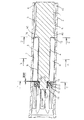
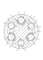
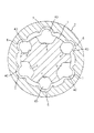
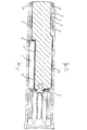
図1は、本発明の第1実施の形態に係る車両ステアリング用伸縮軸の縦断面図である。図2は、図1のX−X線に沿った横断面図である。
【0034】
図1に示すように、車両ステアリング用伸縮軸(以後、伸縮軸と記す)は、相互に回転不能に且つ摺動自在に嵌合した雄軸1と雌軸2とからなる。
【0035】
図2に示すように、雄軸1の外周面には、周方向に120度間隔で等配した3個の軸方向溝3が延在して形成してある。また、この雄軸1の外周面には、これら3個の軸方向溝3の周方向の間であって、周方向に120度間隔で等配した3個の略円弧状の軸方向溝4が延在して形成してある。
【0036】
雌軸2の内周面には、周方向に120度間隔で等配した3個の略円弧状の軸方向溝5が延在して形成してある。また、この雌軸2の内周面には、これら3個の軸方向溝5の周方向の間であって、周方向に120度間隔で等配した3個の略円弧状の軸方向溝6が延在して形成してある。
【0037】
軸方向溝3,5は、後述する3組の第1円柱体7のための3組の第1介装部を構成しており、軸方向溝4,6は、後述する3組の第2円柱体8のための3組の第2介装部を構成している。これら3組の軸方向溝3,5(第1介装部)と、3組の軸方向溝4,6(第2介装部)とは、周方向に交互に配置してあり、周方向に60度間隔で等配してある。
【0038】
第1トルク伝達装置は、雄軸1の3個の軸方向溝3と、雌軸2の3個の軸方向溝5との間に、予圧用の波形形状の3個の弾性体(板バネ)9を介して、雄軸1と雌軸2との軸方向相対移動の際には転動し、回転の際には板バネ9に拘束されてトルクを伝達する3組の第1トルク伝達部材(第1円柱体)7が転動自在に介装して構成されている。
【0039】
第2トルク伝達装置は、雄軸1の3個の軸方向溝4と、雌軸2の3個の軸方向溝6との間に、夫々、雄軸1と雌軸2との軸方向相対移動を許し、回転の際にはトルクを伝達するための3組の第2トルク伝達部材(第2円柱体)8が摺動自在に介装して構成されている。
【0040】
板バネ9は、トルク非伝達時には、第1円柱体7と第2円柱体8を雌軸2に対してガタ付きのない程度に予圧する一方、トルク伝達時には、弾性変形して第1円柱体7を雄軸1と雌軸2の間で周方向に拘束する働きをするようになっている。なお、第1円柱体7と第2円柱体8は、ニードルローラであってもよい。
【0041】
また、軸方向に伸縮運動をする際には、板バネ9によって予圧を受けているニードルローラ7と雌軸の溝5との間で積極的に摺動が発生する。さらに、トルクが負荷されると、板バネ9がたわみ、雄軸1の軸方向溝4とニードルローラ8と雌軸2の軸方向溝6との間で徐々にトルクを受けるようになる。
【0042】
このように、板バネ9の予圧機構により、ニードルローラ7,8を介して3箇所均等に予圧をかけることにより、従来のスプライン構造が根本的に解決できないでいる微小な隙間によるガタを防止することができる。予圧をかける構造で配慮しなければいけないことは、(1)円周上に均等に予圧をかけること、(2)ガタ(フリープレイ)をなくし、ステアリングの操舵感を損なわないように最低限必要な予圧荷重を与えること、(3)十分な耐久性を有すること、である。
【0043】
本実施の形態は、3箇所均等に予圧を必要なだけかけることができ、低入力トルクに対してガタつきを防止できる。しかも、入力トルクが増大した際には、他のニードルローラ8(板バネ9の予圧機構のない箇所)がトルクによる負荷を受けるため、より高い捩り剛性を発生することができる。
【0044】
板バネ9のたわみ量は、雄軸1の軸方向溝4とニードルローラ8と雌軸6との間の微小隙間分だけで、入力トルクが増大しても板バネ9に掛かる負荷、たわみ量は大きく変わらない。よって、板バネ9の性能を長期にわたって保つことができる。
【0045】
さらに、本実施の形態では、トルク伝達部材としてニードルローラ7,8を採用しているが、これは、ニードルローラ7,8が大量生産品で、低コストで採用できること。熱処理、研磨加工してあるため低摺動荷重を実現するとともに高い耐久性(耐摩耗性が高い)を有していること。数ミクロン単位での直径サイズの選択が可能であり、すきま管理が非常に容易であることが挙げられる。
【0046】
従来のスプライン構造では、トルク伝達+摺動により雄軸と雌軸の接触面が摩耗し、隙間の増加がガタつきの増大となりステアリング操舵感の悪化につながっていた。
【0047】
本実施の形態の場合、トルク伝達部材(ニードルローラ7,8)又は軸方向溝5,6が摩耗をしたとしても、板バネ9に予圧をかけているため、雄軸1の軸方向溝3−板バネ9−ニードルローラ7−雌軸2の軸方向溝5間に、隙間は発生しないため、ガタ付きは起こらない。したがって、長期にわたりガタ付きのないトルク伝達特性と低摺動特性を維持することができる。
【0048】
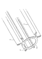
図3は、図1のY−Y線に沿った横断面図である。図4は、連結部により連結した弾性体(板バネ)の斜視図である。図5は、図1の矢印Aの矢視図である。
【0049】
図1に示すように、雄軸1の端部には、小径部1aが形成してある。この小径部1aには、ニードルローラ8の軸方向の移動を規制するストッパープレート10が設けてある。このストッパープレート10は、軸方向予圧用弾性体11と、この軸方向予圧用弾性体11を挟持する1組の平板12,13とからなる。
【0050】
すなわち、本実施の形態では、ストッパープレート10は、小径部1aに、平板13、軸方向予圧用弾性体11、平板12の順に嵌合し、小径部1aに堅固に固定してある。
【0051】
本実施の形態では、雄軸1の小径部1aに、周方向溝31が形成してあり、この周方向溝31に、止め輪32が嵌合してある。これにより、ストッパープレート10が軸方向に固定してある。なお、ストッパープレート10の固定方法は、止め輪32に限らず、加締め、螺合手段、プッシュナット等であってもよい。
【0052】
これにより、ストッパープレート10は、平板13をニードルローラ8に当接させて、軸方向予圧用弾性体11により、ニードルローラ8を軸方向に動かないように適度に予圧できるようになっている。
【0053】
軸方向予圧用弾性体11は、ゴム、樹脂、または鋼板製の板バネなどからできている。軸方向予圧用弾性体11と平板12,13とは、別体でも良いが、組立てやすさを考えて、一体成形品であることが好ましい。
【0054】
例えば、軸方向予圧用弾性体11がゴムであれば、平板12,13に加硫成形するなどして作れば、一体化ができるので、組立てやすく低コストな製品をつくることができる。
【0055】
また、軸方向予圧用弾性体11を樹脂でつくる場合には、波型の形状としたものを、平板12,13と一体成形することで一体化することができ、同様のメリットが得られる。
【0056】
さらに、平板12,13は、鋼板、樹脂、または鋼板に樹脂皮膜を形成したものを使用する。
【0057】
また、雄軸1の軸方向溝3,4は、軸方向に略直角であって、ニードルローラ7やニードルローラ8に当接する軸方向直角面14,15を有している。
【0058】
以上のように、ニードルローラ8の一側は、雄軸1の小径部1aに設けたストッパープレート10により、軸方向の移動が規制してある一方、ニードルローラ8の他側は、軸方向直角面15に当接して、軸方向の移動が規制してある。
【0059】
また、ストッパープレート10は、平板13をニードルローラ8に当接させて、軸方向予圧用弾性体11により、ニードルローラ8を軸方向に動かないように適度に予圧している。
【0060】
従って、ニードルローラ8を適度に予圧して、軸方向に隙間なく固定することができ、雄軸1と雌軸2が相互に摺動する際、ニードルローラ8を軸方向に移動させることがなく、「コツコツ」といった不快な異音の発生を確実に防止することができる。
【0061】
また、雄軸1の軸方向溝3,4は、軸方向に略直角であって、ニードルローラ7,8に当接する軸方向直角面14,15を有していることから、この軸方向直角面15により、別途の部材を設けることなく、ニードルローラ7,8の軸方向の移動を規制することができる。そのため、部品点数を削減して、製造コストの低減を図ることができ、しかも、別途の部材を用いていないことから、軽量・コンパクト化が可能である。
【0062】
次に、本実施の形態では、図1、図3、及び図4に示すように、3組のニードルローラ7を予圧するための3個の板バネ9は、リング状の連結部20によって連結してある。
【0063】
すなわち、図1に示すように、雄軸1の端部の小径部1aには、その段差の環状面21が形成してある。小径部1aに、リング状の連結部20が嵌合してあり、この段差の環状面21に沿って、リング状の連結部20が配置してある。
【0064】
段差の環状面21は、雄軸1の軸方向に面する軸方向環状面であれば、その形状等は問わない。
【0065】
リング状の連結部20は、その周縁の3箇所で、3個の板バネ9の軸方向端部に連結してある。即ち、図4に示すように、リング状の連結部20は、軸方向に延在した3個の板バネ9と一体的に構成してある。
【0066】
従って、ニードルローラ7,8を複合させた構造でありながら、転動面である3個の板バネ9を一体化して、実質上の部品点数を3個から1個に減らすことができ、部品点数を削減し、組立性を向上させて、組立時間を短縮して、製造コストを低減することができる。
【0067】
また、リング状の連結部20は、従来のような周方向に延びる円弧状の連結部でないことから、雌軸2を径方向に拡径することなく、コンパクト化を図ることができる。
【0068】
さらに、リング状の連結部20に、雄軸1の端部に形成した小径部1aが貫通してある。従って、3個の板バネ9の組み込み時、雄軸1の端部の小径部1aは、リング状の連結部20に通挿することにより、この組み込み時のガイドの役割を果たすことから、組み込み作業を容易にでき、組み込み時間を短縮して、製造コストの低減を図ることができる。
【0069】
さらに、リング状の連結部20は、ストッパープレート10の平板13と、段差の環状面21との間の軸方向隙間に配置してある。この軸方向隙間は、例えば、約0.3〜2.0mmである。
【0070】
この軸方向隙間の存在により、リング状の連結部20は、3個の板バネ9がトルク入力により変形した際にも、これら板バネ9の動きを拘束しないようになっている。
【0071】
さらに、図3及び図4に示すように、各板バネ9の断面形状は、雄軸1の軸方向溝3の形状とほぼ平行な直線形状に形成してあり、中心部分の平面部に、リング状の連結部20の周縁箇所が連結してある。各板バネ9の両端部は、中心側から外側に向けて折り返して形成してある。
【0072】
さらに、リング状の連結部20に、雄軸1の端部に形成した小径部1aが貫通してある。雄軸1の小径部1aと、リング状の連結部20との間には、径方向隙間が形成してある。この径方向隙間は、例えば、0.2〜1.0mmである。上記の軸方向隙間と同様に、この径方向隙間の存在により、リング状の連結部20は、3個の板バネ9がトルク入力により変形した際にも、これら板バネ9の動きを拘束しないようになっている。
【0073】
次に、図1及び図6に示すように、本実施の形態では、雌軸2の6個の軸方向溝5,6に、径方向に隙間を介して、雄軸1の外周面に6個の軸方向溝3,4と軸方向に同軸に形成した6個の略円弧状の突起部40が嵌合してある。
【0074】
従って、ニードルローラ7,8が何らかの原因によって雄軸1から脱落し又は破損した場合等には、雌軸2の軸方向溝5,6に、雄軸1の突起部40が嵌合し、これにより、雄軸1と雌軸2とは、トルクを伝達することができ、フェイルセーフ機能の役割を果たすことができる。
【0075】
また、この際、図6に示すように、軸方向溝5,6と、突起部40との間には、隙間が設けてあるため、運転者は、ステアリングホイール上に大きなガタ付きを感じることができ、ステアリング系の故障等を察知することができる。
【0076】
さらに、図1に示すように、雄軸1の突起部40は、雄軸1の軸方向溝3,4と軸方向に同軸に形成してあり、ニードルローラ7,8とも軸方向に同軸であることから、ニードルローラ7,8の軸方向の移動を規制するストッパーの役割も果たし、ニードルローラ7,8の抜けの可能性を減少して、フェイルセーフ機能をより一層向上することができる。
【0077】
さらに、雄軸1の突起部40は、雄軸1の軸方向溝3,4と軸方向に同軸に形成してあり、ニードルローラ7,8とも軸方向に同軸であることから、雄軸1と雌軸2の径方向寸法を小さくして、コンパクト化を図ることができる。
【0078】
また、雄軸1の突起部40は、上記のように、ニードルローラ7,8と軸方向に同軸であり、その上、ニードルローラ7,8の周方向における組数と、突起部40の周方向における個数とが同一に設定してあることから、ニードルローラ7,8の軸方向の移動を規制するストッパーの役割を確実に果たすことができ、ニードルローラ7,8の抜けの可能性をより一層減少することができる。
【0079】
さらに、雌軸2の端部は、その内方に向けて変形した内方変形部41を有している。この内方変形部41は、具体的には、雌軸2の端部を加締めて形成してある。
【0080】
これにより、雄軸1を雌軸2から抜ける方向に相対移動させた時、雌軸2の端部に形成した内方変形部41(例えば、加締め部)に、雄軸1の突起部40が係止(干渉)する。これにより、雄軸1は、雌軸2からむやみに分離できない構造になっている。
【0081】
(第2実施の形態)
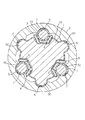
次に、図7は、本発明の第2実施の形態に係る車両ステアリング用伸縮軸の横断面図である。
【0082】
本実施の形態では、第1実施の形態に対し、更に摺動荷重を低くしたい場合には、トルク伝達部材であるニードルローラ7,8の表面に固体潤滑皮膜50を形成する。摺動荷重は、摩擦係数に負荷された荷重を乗じたものであるため、摩擦係数を低くすることができれば摺動荷重を低くすることができる。よって、固体潤滑皮膜50を形成して、摩擦係数を小さくすることで更なる低摺動荷重を実現することができる。
【0083】
固体潤滑皮膜の形成方法としては、(1)二硫化モリブデンの紛体をバインダー中に分散子混合し、それを吹きつけ、または、浸漬後に焼き付けて皮膜を形成する方法、(2)PTFE(四フッ化エチレン)の紛体をバインダー中に分散子混合し、それを吹きつけ、または、浸漬後に焼き付けて皮膜を形成する方法がある。
【0084】
また、図8は、本発明の第2実施の形態の第1変形例に係る車両ステアリング用伸縮軸の横断面図である。
【0085】
本変形例では、ニードルローラ7,8の表面に、固体潤滑皮膜50を形成すると共に、雌軸2の内周面には、固体潤滑皮膜80が形成してある。
【0086】
摺動荷重は、摩擦係数に負荷された荷重を乗じたものであるため、摩擦係数を低くすることができれば、摺動荷重を低くすることができる。よって、固体潤滑皮膜80を形成して、摩擦係数を小さくすることで、更なる低摺動荷重を実現することができる。固体潤滑皮膜の形成方法は、上述した場合と同様である。
【0087】
さらに、図9は、本発明の第2実施の形態の第2変形例に係る車両ステアリング用伸縮軸の横断面図である。
【0088】
本変形例では、ニードルローラ7,8に、固体潤滑皮膜50を形成することなく、雌軸2の内周面にのみ、固体潤滑皮膜80が形成してある。
【0089】
摺動荷重は、摩擦係数に負荷された荷重を乗じたものであるため、摩擦係数を低くすることができれば、摺動荷重を低くすることができる。よって、固体潤滑皮膜80を形成して、摩擦係数を小さくすることで、更なる低摺動荷重を実現することができる。固体潤滑皮膜の形成方法は、上述した場合と同様である。
【0090】
(第3実施の形態)
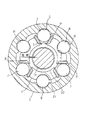
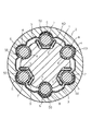
図10は、本発明の第3実施の形態に係る車両ステアリング用伸縮軸の縦断面図である。図11は、図10のX−X線に沿った横断面図である。
【0091】
本実施の形態では、第1実施の形態に対し、板バネ9による予圧の掛かっていない箇所のニードルローラ8を廃止し、その代わりに、雄軸1に軸方向突条部60が一体的に形成してある。
【0092】
このように、ニードルローラ8を3箇所廃止できるため、部品点数削減効果により、コストダウンが可能である。
【0093】
雄軸1の軸方向突条部60と、雌軸2の軸方向溝6との凹凸形状は、トルクの伝達が可能であれば、いかなる形状であってもよいい。例えば、セレーション、スプライン形状でもよい。
【0094】
なお、軸方向突条部は、必ずしも雄軸に設ける必要がなく、雄軸1の外周面には、軸方向溝を形成して、雌軸2の内周面に、軸方向突条部が形成してあってもよい。
【0095】
また、軸方向突条部60を含む雄軸1の表面には、固体潤滑皮膜70を形成する。摺動荷重は、摩擦係数に負荷された荷重を乗じたものであるため、摩擦係数を低くすることができれば摺動荷重を低くすることができる。よって、固体潤滑皮膜70を形成して、摩擦係数を小さくすることで更なる低摺動荷重を実現することができる。固体潤滑皮膜の形成方法は、上述した場合と同様である。なお、予圧を受けているニードルローラ7には、固体潤滑皮膜は形成していない。
【0096】
さらに、図10に示すように、軸方向のストッパー部品として、ストッパープレート10が小径部1aの端部1bに加締め固定してある。ストッパープレート10には、特に弾性体ははさみこまれていないが、ニードルローラ7,8を軸方向に隙間なく確実に固定できれば、図10に示す構造であっても良い。
【0097】
(第4実施の形態)
次に、図12は、本発明の第4実施の形態に係る車両ステアリング用伸縮軸の横断面図である。
【0098】
本実施の形態では、第3実施の形態に対し、更に摺動荷重を低くしたい場合には、トルク伝達部材であるニードルローラ7,8の表面に固体潤滑皮膜50を形成する。摺動荷重は、摩擦係数に負荷された荷重を乗じたものであるため、摩擦係数を低くすることができれば摺動荷重を低くすることができる。よって、固体潤滑皮膜50を形成して、摩擦係数を小さくすることで更なる低摺動荷重を実現することができる。固体潤滑皮膜の形成方法は、上述した場合と同様である。
【0099】
また、図13は、本発明の第4実施の形態の第1変形例に係る車両ステアリング用伸縮軸の横断面図である。
【0100】
本変形例では、雄軸1の表面に、固体潤滑皮膜70を形成することなく、雌軸2の内周面にのみ、固体潤滑皮膜80が形成してある。
【0101】
摺動荷重は、摩擦係数に負荷された荷重を乗じたものであるため、摩擦係数を低くすることができれば、摺動荷重を低くすることができる。よって、固体潤滑皮膜80を形成して、摩擦係数を小さくすることで、更なる低摺動荷重を実現することができる。固体潤滑皮膜の形成方法は、上述した場合と同様である。
【0102】
なお、本発明は、上述した実施の形態に限定されず、種々変形可能である。
【0103】
【発明の効果】
以上説明したように、本発明の請求項1によれば、トルク非伝達時(軸方向相対移動時)には、弾性体により、第1及び第2トルク伝達部材を雌軸に対してガタ付きのない程度に径方向及び周方向に予圧しているため、雄軸と雌軸の間のガタ付きを確実に防止することができると共に、雄軸と雌軸は、ガタ付きのない安定した摺動荷重で軸方向に摺動することができる。
【0104】
トルク伝達時、弾性体により、第1及び第2トルク伝達部材を周方向に拘束できるようになっているため、雄軸と雌軸の間の回転方向ガタ付きを確実に防止して、高剛性の状態でトルクを伝達することができる。
【0105】
また、請求項1によれば、第1及び第2トルク伝達部材は、夫々、円柱体からなり、トルク非伝達時(軸方向相対移動時)には、弾性体により、円柱体を雌軸に対してガタ付きのない程度に径方向及び周方向に予圧しているため、雄軸と雌軸との間のガタ付きを確実に防止することができると共に、雄軸と雌軸は、ガタ付きのない安定した摺動荷重で軸方向に摺動することができる。また、トルク伝達時、弾性体により、円柱体を周方向に拘束できるようになっているため、雄軸と雌軸の間の回転方向ガタ付きを確実に防止して、高剛性の状態でトルクを伝達することができる。
【0106】
さらに、請求項2によれば、更に摺動荷重を低くしたい場合は、第1及び第2トルク伝達部材である円柱体(ニードルローラ)の表面に、固体潤滑皮膜を形成する。摺動荷重は、摩擦係数に負荷された荷重を乗じたものであるため、摩擦係数を低くすることができれば摺動荷重を低くすることができる。よって、固体潤滑皮膜を形成して、摩擦係数を小さくすることで更なる低摺動荷重を実現することができる。
【0107】
さらに、請求項3によれば、雌軸の内周面に、固体潤滑皮膜を形成して、摩擦係数を小さくすることで更なる低摺動荷重を実現することができる。
【0108】
さらに、請求項4によれば、雌軸の内周面と雄軸の外周面との一方に形成した軸方向溝と、該軸方向溝に嵌合するように、雄軸の外周面と雌軸の内周面との他方に形成し、雄軸と雌軸との軸方向相対移動の際には摺動し、回転の際にはトルクを伝達する軸方向突条部と、からなる第2のトルク伝達装置を備えている。
【0109】
従って、トルク非伝達時(軸方向相対移動時)には、弾性体により、トルク伝達部材と軸方向突条部をガタ付きのない程度に径方向及び周方向に予圧しているため、雄軸と雌軸の間のガタ付きを確実に防止することができると共に、雄軸と雌軸は、ガタ付きのない安定した摺動荷重で軸方向に摺動することができる。また、トルク伝達時、弾性体により、トルク伝達部材と軸方向突条部を周方向に拘束できるようになっているため、雄軸と雌軸の間の回転方向ガタ付きを確実に防止して、高剛性の状態でトルクを伝達することができる。
【0110】
また、雄軸の外周面と雌軸の内周面との他方には、トルクを伝達する軸方向突条部が設けてあるため、上述した請求項1乃至3における第2トルク伝達部材を廃止することができ、部品点数を削減し、組立作業を容易して製造コストを低減することができる。
【0111】
さらに、請求項4によれば、トルク非伝達時(軸方向相対移動時)には、弾性体により、円柱体と軸方向突条部をガタ付きのない程度に径方向及び周方向に予圧しているため、雄軸と雌軸の間のガタ付きを確実に防止することができると共に、雄軸と雌軸は、ガタ付きのない安定した摺動荷重で軸方向に摺動することができる。また、トルク伝達時、弾性体により、円柱体と軸方向突条部を周方向に拘束できるようになっているため、雄軸と雌軸の間の回転方向ガタ付きを確実に防止して、高剛性の状態でトルクを伝達することができる。
【0112】
さらに、請求項5によれば、円柱体の表面に、固体潤滑皮膜を形成して、摩擦係数を小さくすることで更なる低摺動荷重を実現することができる。
【0113】
さらに、請求項6によれば、雌軸の内周面に、固体潤滑皮膜を形成して、摩擦係数を小さくすることで更なる低摺動荷重を実現することができる。
【0114】
さらに、請求項7によれば、雄軸の外周面に、固体潤滑皮膜を形成して、摩擦係数を小さくすることで更なる低摺動荷重を実現することができる。
【図面の簡単な説明】
【図1】本発明の第1実施の形態に係る車両ステアリング用伸縮軸の縦断面図である。
【図2】図1のX−X線に沿った横断面図である。
【図3】図1のY−Y線に沿った横断面図である。
【図4】連結部により連結した弾性体(板バネ)の斜視図である。
【図5】図1の矢印Aの矢視図である。
【図6】図1のZ−Z線に沿った横断面図である。
【図7】本発明の第2実施の形態に係る車両ステアリング用伸縮軸の横断面図である。
【図8】本発明の第2実施の形態の第1変形例に係る車両ステアリング用伸縮軸の横断面図である。
【図9】本発明の第2実施の形態の第2変形例に係る車両ステアリング用伸縮軸の横断面図である。
【図10】本発明の第3実施の形態に係る車両ステアリング用伸縮軸の縦断面図である。
【図11】図10のX−X線に沿った横断面図である。
【図12】本発明の第4実施の形態に係る車両ステアリング用伸縮軸の横断面図である。
【図13】本発明の第4実施の形態の第1変形例に係る車両ステアリング用伸縮軸の横断面図である。
【図14】一般的な自動車の操舵機構部の側面図である。
【符号の説明】
1 雄軸
1a 小径部
1b 加締め部
2 雌軸
3,4 軸方向溝(第1介装部)
5,6 軸方向溝(第2介装部)
7 第1円柱体(ニードルローラ、第1トルク伝達部材)
8 第2円柱体(ニードルローラ、第2トルク伝達部材)
9 弾性体(板バネ)
10 ストッパープレート
11 軸方向予圧用弾性体
12,13 平板
14,15 軸方向直角面
20 リング状の連結部
21 段差の環状面(軸方向環状面)
31 周方向溝
32 止め輪
40 突起部
41 内方変形部(加締め部)
50 固体潤滑皮膜
60 軸方向突状部
70 固体潤滑皮膜
80 固体潤滑皮膜[0001]
BACKGROUND OF THE INVENTION
The present invention relates to a telescopic shaft for vehicle steering that realizes a stable sliding load, reliably prevents rattling and can transmit torque in a highly rigid state.
[0002]
[Prior art]
FIG. 14 shows a general automobile steering mechanism. In the drawing, a and b are telescopic axes. The telescopic shaft a is a spline fit between a male shaft and a female shaft. The telescopic shaft a absorbs axial displacement that occurs when the automobile travels, and the Performance that does not transmit displacement or vibration is required. In such a performance, the vehicle body has a sub-frame structure, and a part c for fixing the upper part of the steering mechanism and a frame e to which the steering rack d is fixed are separated, and an elastic body f such as rubber is provided between them. Generally, it is required in the case of a structure that is fastened and fixed via In other cases, when the steering shaft joint g is fastened to the pinion shaft h, an operator may need to have a telescopic function in order to retract the telescopic shaft once and then fit the pinion shaft h to fasten it. . Further, the telescopic shaft b at the upper part of the steering mechanism is a spline-fitting of the male shaft and the female shaft, and the telescopic shaft b is in an optimal position for the driver to drive the automobile. Therefore, the function of moving the position of the steering wheel i in the axial direction and adjusting the position is required, and thus the function of expanding and contracting in the axial direction is required. In all the cases described above, the telescopic shaft is required to reduce the rattling noise of the spline, to reduce the rattling on the steering wheel, and to reduce the sliding resistance during the axial sliding operation. Is done.
[0003]
For this reason, in
[0004]
Each set of torque transmission members (cylindrical bodies) includes a plurality of needle rollers arranged in parallel in the axial direction.
[0005]
This prevents backlash between the male shaft and the female shaft when torque is not transmitted (when sliding), and the male shaft and female shaft can be driven with a stable sliding load without backlash. Can slide in the direction. Further, at the time of torque transmission, the male shaft and the female shaft can prevent backlash in the rotational direction and transmit torque in a highly rigid state.
[0006]
Further, a resin adjustment member (cage) is provided to prevent the needle roller from rattling in the rotational direction (circumferential direction).
[0007]
[Patent Document 1]
European Patent Application Publication No. EP1078843A1
[0008]
[Problems to be solved by the invention]
In
[0009]
However, the adjustment member (cage) made of resin has a problem in wear resistance, and it is difficult to maintain the performance without rattling over a long period of time. Therefore, when wear occurs, the steering shaft may feel loose.
[0010]
In addition, since the telescopic shaft of
[0011]
The present invention has been made in view of the circumstances as described above, achieves a stable sliding load, reliably prevents backlash in the rotational direction, and can transmit torque in a highly rigid state. Moreover, it is an object of the present invention to provide a telescopic shaft for vehicle steering that can reduce the number of parts, facilitate assembly work, and reduce manufacturing costs while achieving compactness.
[0012]
[Means for Solving the Problems]
In order to achieve the above object, a telescopic shaft for vehicle steering according to
A first interposed portion provided on an outer peripheral surface of the male shaft and an inner peripheral surface of the female shaft; and the relative movement in the axial direction between the male shaft and the female shaft disposed on the first interposed portion. In Against the female shaft A first torque transmission member made of a sliding cylindrical body, and disposed adjacent to the first torque transmission member between the first torque transmission member and the male shaft in the first interposition part; A first torque transmission device comprising: a leaf spring that restrains the first torque transmission member when pre-rotating and preloads the first torque transmission member against the female shaft when non-rotating;
The outer peripheral surface of the male shaft An axial groove formed at a predetermined interval in the circumferential direction with the first torque transmission device When Facing the axial groove Inner peripheral surface of the female shaft Axial groove formed in When Consisted of In the case of relative movement in the axial direction between the male shaft and the female shaft disposed on the second interposed portion and the second interposed portion For the axial groove formed in the female shaft When sliding and rotating In contact with the axial groove formed in the male shaft and the axial groove formed in the female shaft. And a second torque transmission device comprising a second torque transmission member comprising a cylindrical body for transmitting torque.
[0013]
Thus, according to the first aspect of the present invention, when torque is not transmitted (during relative movement in the axial direction), the first and second torque transmitting members are not rattled with respect to the female shaft by the elastic body. Preload in the radial and circumferential directions to the extent that it can reliably prevent rattling between the male and female shafts, and the male and female shafts are stable sliding loads without rattling. Can slide in the axial direction.
[0014]
During torque transmission, the elastic body can restrain the first and second torque transmission members in the circumferential direction, thus reliably preventing backlash in the rotational direction between the male shaft and the female shaft. Torque can be transmitted in this state.
[0016]
Thus, the
[0017]
And claims 2 The telescopic shaft for vehicle steering according to the present invention is characterized in that a solid friction film of low friction is formed on the surface of the cylindrical body.
[0018]
Thus, the
[0019]
And claims 3 The vehicle steering telescopic shaft according to the present invention is characterized in that a low-friction solid lubricating film is formed on the inner peripheral surface of the female shaft.
Thus, the
[0020]
And claims 4 The telescopic shaft for vehicle steering according to the present invention is a telescopic shaft for vehicle steering that is incorporated in a steering shaft of a vehicle and has a male shaft and a female shaft fitted so as to be able to transmit torque and relatively move.
An interposed portion provided on the outer peripheral surface of the male shaft and the inner peripheral surface of the female shaft, and slides when the male shaft and the female shaft move relative to each other in the axial direction. Do Consists of cylinders Torque transmission member and the interposition part Between the torque transmission member and the male shaft Arranged adjacent to the torque transmission member, restrains the torque transmission member during rotation, and non-rotation A leaf spring for preloading the torque transmitting member against the female shaft A first torque transmission device comprising:
An axial groove formed on one of the inner peripheral surface of the female shaft and the outer peripheral surface of the male shaft, and the outer peripheral surface of the male shaft and the inner peripheral surface of the female shaft so as to fit in the axial groove A second torque comprising an axial ridge that slides when the male shaft and the female shaft move relative to each other in the axial direction and transmits torque when rotated. And a transmission device.
[0021]
Thus, the claim 4 According to the present invention, the axial groove formed on one of the inner peripheral surface of the female shaft and the outer peripheral surface of the male shaft, and the outer peripheral surface of the male shaft and the inner peripheral surface of the female shaft so as to fit in the axial groove A second torque transmission device including an axial protrusion that slides when the male shaft and the female shaft move relative to each other in the axial direction and transmits torque when rotating. It has.
[0022]
Therefore, when torque is not transmitted (in the axial relative movement), the elastic body preloads the torque transmitting member and the axial ridge in the radial and circumferential directions to the extent that there is no backlash. And the female shaft can be surely prevented, and the male shaft and the female shaft can slide in the axial direction with a stable sliding load without backlash. Also, during torque transmission, the elastic body can restrain the torque transmission member and the axial ridge in the circumferential direction, thus reliably preventing backlash between the male shaft and female shaft. Torque can be transmitted in a highly rigid state.
[0023]
Moreover, since the axial direction protrusion part which transmits a torque is provided in the other of the outer peripheral surface of a male shaft, and the internal peripheral surface of a female shaft, the 2nd torque transmission member in
[0025]
Thus, the claim 4 Therefore, when torque is not transmitted (relative movement in the axial direction), the cylindrical body and the axial ridge are preloaded in the radial direction and the circumferential direction to the extent that there is no play by the elastic body. The backlash between the shaft and the female shaft can be reliably prevented, and the male shaft and the female shaft can slide in the axial direction with a stable sliding load without backlash. In addition, since the cylindrical body and the axial ridge portion can be restrained in the circumferential direction by the elastic body during torque transmission, the backlash in the rotational direction between the male shaft and the female shaft is reliably prevented, Torque can be transmitted in a highly rigid state.
[0026]
And claims 5 The telescopic shaft for vehicle steering according to the present invention is characterized in that a solid friction film of low friction is formed on the surface of the cylindrical body.
[0027]
Thus, the
[0028]
And claims 6 The vehicle steering telescopic shaft according to the present invention is characterized in that a low-friction solid lubricating film is formed on the inner peripheral surface of the female shaft.
[0029]
Thus, the
[0030]
And claims 7 In the vehicle steering telescopic shaft according to the present invention, a low-friction solid lubricant film is formed on the outer peripheral surface of the male shaft.
[0031]
Thus, the
[0032]
DETAILED DESCRIPTION OF THE INVENTION
Hereinafter, a telescopic shaft for vehicle steering according to an embodiment of the present invention will be described with reference to the drawings.
[0033]
(First embodiment)
FIG. 1 is a longitudinal sectional view of a telescopic shaft for vehicle steering according to a first embodiment of the present invention. FIG. 2 is a cross-sectional view taken along line XX of FIG.
[0034]
As shown in FIG. 1, the vehicle steering telescopic shaft (hereinafter referred to as the telescopic shaft) is composed of a
[0035]
As shown in FIG. 2, three
[0036]
On the inner peripheral surface of the
[0037]
The
[0038]
The first torque transmission device includes three elastic bodies (plate springs) having a wavy shape for preload between the three
[0039]
The second torque transmission device includes an axial relative relationship between the
[0040]
The
[0041]
In addition, when the telescopic movement is performed in the axial direction, the sliding is positively generated between the
[0042]
As described above, the preload mechanism of the
[0043]
In the present embodiment, preload can be applied evenly at three locations as necessary, and rattling can be prevented with respect to low input torque. In addition, when the input torque increases, the other needle roller 8 (the portion without the preload mechanism of the leaf spring 9) receives a load due to the torque, so that higher torsional rigidity can be generated.
[0044]
The amount of deflection of the
[0045]
Further, in the present embodiment, the
[0046]
In the conventional spline structure, the contact surface between the male shaft and the female shaft is worn by torque transmission + sliding, and the increase in the gap increases the backlash, resulting in deterioration of the steering feeling.
[0047]
In the case of this embodiment, even if the torque transmission member (
[0048]
FIG. 3 is a cross-sectional view taken along line YY of FIG. FIG. 4 is a perspective view of an elastic body (plate spring) connected by a connecting portion. FIG. 5 is an arrow view of arrow A in FIG.
[0049]
As shown in FIG. 1, a
[0050]
That is, in the present embodiment, the
[0051]
In the present embodiment, a
[0052]
As a result, the
[0053]
The axial preload
[0054]
For example, if the
[0055]
Further, when the
[0056]
Further, the
[0057]
Further, the
[0058]
As described above, one side of the
[0059]
The
[0060]
Accordingly, the
[0061]
Further, since the
[0062]
Next, in this embodiment, as shown in FIGS. 1, 3, and 4, the three
[0063]
That is, as shown in FIG. 1, an
[0064]
As long as the
[0065]
The ring-shaped connecting
[0066]
Accordingly, although the
[0067]
Moreover, since the ring-shaped
[0068]
Further, a
[0069]
Further, the ring-shaped connecting
[0070]
Due to the existence of the axial gap, the ring-shaped connecting
[0071]
Further, as shown in FIGS. 3 and 4, the cross-sectional shape of each
[0072]
Further, a
[0073]
Next, as shown in FIGS. 1 and 6, in the present embodiment, 6
[0074]
Accordingly, when the
[0075]
Further, at this time, as shown in FIG. 6, since a gap is provided between the
[0076]
Further, as shown in FIG. 1, the
[0077]
Further, the
[0078]
Further, as described above, the
[0079]
Further, the end portion of the
[0080]
As a result, when the
[0081]
(Second Embodiment)
Next, FIG. 7 is a cross-sectional view of the telescopic shaft for vehicle steering according to the second embodiment of the present invention.
[0082]
In the present embodiment, the
[0083]
As a method for forming a solid lubricating film, (1) a method in which a powder of molybdenum disulfide is mixed in a binder and sprayed or baked after immersion is formed, and (2) PTFE (four foot). There is a method of forming a film by mixing a powder of ethylene fluoride) in a binder and spraying it, or baking it after immersion.
[0084]
FIG. 8 is a cross-sectional view of a telescopic shaft for vehicle steering according to a first modification of the second embodiment of the present invention.
[0085]
In this modification, a
[0086]
Since the sliding load is obtained by multiplying the friction coefficient by the load applied, the sliding load can be lowered if the friction coefficient can be lowered. Therefore, by forming the
[0087]
FIG. 9 is a cross-sectional view of a telescopic shaft for vehicle steering according to a second modification of the second embodiment of the present invention.
[0088]
In this modification, the
[0089]
Since the sliding load is obtained by multiplying the friction coefficient by the load applied, the sliding load can be lowered if the friction coefficient can be lowered. Therefore, by forming the
[0090]
(Third embodiment)
FIG. 10 is a longitudinal sectional view of a telescopic shaft for vehicle steering according to the third embodiment of the present invention. 11 is a cross-sectional view taken along line XX in FIG.
[0091]
In this embodiment, in contrast to the first embodiment, the
[0092]
Thus, since the
[0093]
The uneven shape of the
[0094]
The axial ridge is not necessarily provided on the male shaft. An axial groove is formed on the outer peripheral surface of the
[0095]
A
[0096]
Further, as shown in FIG. 10, a
[0097]
(Fourth embodiment)
Next, FIG. 12 is a cross-sectional view of a telescopic shaft for vehicle steering according to a fourth embodiment of the present invention.
[0098]
In the present embodiment, the
[0099]
FIG. 13 is a cross-sectional view of a telescopic shaft for vehicle steering according to a first modification of the fourth embodiment of the present invention.
[0100]
In this modification, the
[0101]
Since the sliding load is obtained by multiplying the friction coefficient by the load applied, the sliding load can be lowered if the friction coefficient can be lowered. Therefore, by forming the
[0102]
In addition, this invention is not limited to embodiment mentioned above, A various deformation | transformation is possible.
[0103]
【The invention's effect】
As described above, according to
[0104]
During torque transmission, the elastic body can restrain the first and second torque transmission members in the circumferential direction, thus reliably preventing backlash in the rotational direction between the male shaft and the female shaft. Torque can be transmitted in this state.
[0105]
[0106]
And claims 2 According to the above, when it is desired to further reduce the sliding load, a solid lubricating film is formed on the surfaces of the cylindrical bodies (needle rollers) which are the first and second torque transmission members. Since the sliding load is obtained by multiplying the friction coefficient by the load applied, the sliding load can be lowered if the friction coefficient can be lowered. Therefore, a further low sliding load can be realized by forming a solid lubricating film and reducing the friction coefficient.
[0107]
And claims 3 Accordingly, a further low sliding load can be realized by forming a solid lubricating film on the inner peripheral surface of the female shaft and reducing the friction coefficient.
[0108]
And claims 4 According Female shaft An axial groove formed on one of the inner peripheral surface of the male shaft and the outer peripheral surface of the male shaft, and the other of the outer peripheral surface of the male shaft and the inner peripheral surface of the female shaft so as to fit into the axial groove. A second torque transmission device comprising an axial ridge that slides in the axial relative movement between the male shaft and the female shaft and transmits torque in the rotation is provided.
[0109]
Therefore, when torque is not transmitted (in the axial relative movement), the elastic body preloads the torque transmitting member and the axial ridge in the radial and circumferential directions to the extent that there is no backlash. And the female shaft can be surely prevented, and the male shaft and the female shaft can slide in the axial direction with a stable sliding load without backlash. Also, during torque transmission, the elastic body can restrain the torque transmission member and the axial ridge in the circumferential direction, thus reliably preventing backlash between the male shaft and female shaft. Torque can be transmitted in a highly rigid state.
[0110]
Moreover, since the axial direction ridge part which transmits a torque is provided in the other of the outer peripheral surface of a male shaft, and the inner peripheral surface of a female shaft, the above-mentioned
[0111]
And claims 4 Therefore, when torque is not transmitted (relative movement in the axial direction), the cylindrical body and the axial ridge are preloaded in the radial direction and the circumferential direction to the extent that there is no play by the elastic body. The backlash between the shaft and the female shaft can be reliably prevented, and the male shaft and the female shaft can slide in the axial direction with a stable sliding load without backlash. In addition, since the cylindrical body and the axial ridge portion can be restrained in the circumferential direction by the elastic body during torque transmission, the backlash in the rotational direction between the male shaft and the female shaft is reliably prevented, Torque can be transmitted in a highly rigid state.
[0112]
And claims 5 According to the cylinder body A further low sliding load can be realized by forming a solid lubricating film on the surface of the material and reducing the friction coefficient.
[0113]
And claims 6 Accordingly, a further low sliding load can be realized by forming a solid lubricating film on the inner peripheral surface of the female shaft and reducing the friction coefficient.
[0114]
And claims 7 According to this, a further low sliding load can be realized by forming a solid lubricating film on the outer peripheral surface of the male shaft and reducing the friction coefficient.
[Brief description of the drawings]
FIG. 1 is a longitudinal sectional view of a telescopic shaft for vehicle steering according to a first embodiment of the present invention.
FIG. 2 is a cross-sectional view taken along line XX of FIG.
3 is a cross-sectional view taken along line YY in FIG.
FIG. 4 is a perspective view of an elastic body (plate spring) connected by a connecting portion.
FIG. 5 is a view taken in the direction of arrow A in FIG. 1;
6 is a cross-sectional view taken along the line ZZ in FIG. 1. FIG.
FIG. 7 is a cross-sectional view of a telescopic shaft for vehicle steering according to a second embodiment of the present invention.
FIG. 8 is a cross-sectional view of a telescopic shaft for vehicle steering according to a first modification of the second embodiment of the present invention.
FIG. 9 is a cross-sectional view of a telescopic shaft for vehicle steering according to a second modification of the second embodiment of the present invention.
FIG. 10 is a longitudinal sectional view of a telescopic shaft for vehicle steering according to a third embodiment of the present invention.
11 is a cross-sectional view taken along line XX of FIG.
FIG. 12 is a cross-sectional view of a telescopic shaft for vehicle steering according to a fourth embodiment of the present invention.
FIG. 13 is a cross-sectional view of a telescopic shaft for vehicle steering according to a first modification of the fourth embodiment of the present invention.
FIG. 14 is a side view of a general automobile steering mechanism.
[Explanation of symbols]
1 Male axis
1a Small diameter part
1b Caulking part
2 Female shaft
3, 4 Axial grooves (first intervention part)
5,6 Axial groove (second intervention part)
7 First cylindrical body (needle roller, first torque transmission member)
8 Second cylindrical body (needle roller, second torque transmission member)
9 Elastic body (leaf spring)
10 Stopper plate
11 Axial preload elastic body
12,13 flat plate
14,15 Axial perpendicular plane
20 Ring-shaped connecting part
21 Stepped annular surface (annular annular surface)
31 circumferential groove
32 retaining ring
40 Protrusion
41 Inner deformation part (caulking part)
50 Solid lubricant film
60 Axial protrusion
70 Solid lubricant film
80 Solid lubricant film
Claims (7)
前記雄軸の外周面と前記雌軸の内周面とに設けられた第1介装部と、該第1介装部に配置され前記雄軸と前記雌軸との軸方向相対移動の際には前記雌軸に対して摺動する円柱体からなる第1トルク伝達部材と、前記第1介装部において前記第1トルク伝達部材と前記雄軸との間に前記第1トルク伝達部材に隣接して配置され、回転の際には前記第1トルク伝達部材を拘束し、非回転の際には前記雌軸に対して前記第1トルク伝達部材を予圧する板バネと、からなる第1のトルク伝達装置と、
前記雄軸の外周面に前記第1のトルク伝達装置と周方向に所定の間隔で形成された軸方向溝と該軸方向溝に対向して前記雌軸の内周面に形成された軸方向溝とで構成された第2介装部と、該第2介装部に配置され前記雄軸と前記雌軸との軸方向相対移動の際には前記雌軸に形成された前記軸方向溝に対して摺動し、回転の際には前記雄軸に形成された前記軸方向溝および前記雌軸に形成された前記軸方向溝に接触してトルクを伝達する円柱体からなる第2トルク伝達部材とからなる第2のトルク伝達装置と、を具備することを特徴とする車両ステアリング用伸縮軸。In a telescopic shaft for vehicle steering that is incorporated in a steering shaft of a vehicle and fitted so that a male shaft and a female shaft can transmit torque and can move relative to each other in the axial direction .
A first interposed portion provided on an outer peripheral surface of the male shaft and an inner peripheral surface of the female shaft; and the relative movement in the axial direction between the male shaft and the female shaft disposed on the first interposed portion. Includes a first torque transmission member formed of a cylindrical body that slides with respect to the female shaft, and the first torque transmission member between the first torque transmission member and the male shaft in the first interposition part. A leaf spring disposed adjacent to the first torque transmission member for restraining the first torque transmission member when rotating and preloading the first torque transmission member against the female shaft when not rotating; A torque transmission device of
Said first torque transfer device in the circumferential direction opposite to the axial grooves and the axial direction groove formed at predetermined intervals axially formed on the inner peripheral surface of said female shaft to the outer peripheral surface of said male shaft A second interposed portion constituted by a groove , and the axial groove formed in the female shaft when the male shaft and the female shaft are moved relative to each other in the axial direction. A second torque comprising a cylindrical body that slides against and transmits torque in contact with the axial groove formed on the male shaft and the axial groove formed on the female shaft when rotating. A telescopic shaft for vehicle steering, comprising: a second torque transmission device including a transmission member.
前記雄軸の外周面と前記雌軸の内周面とに設けられた介装部と、該介装部に配置され前記雄軸と前記雌軸との軸方向相対移動の際には摺動する円柱体からなるトルク伝達部材と、前記介装部において前記トルク伝達部材と前記雄軸との間に前記トルク伝達部材に隣接して配置され、回転の際には前記トルク伝達部材を拘束し、非回転の際には前記雌軸に対して前記トルク伝達部材を予圧する板バネと、からなる第1のトルク伝達装置と、
前記雌軸の内周面と前記雄軸の外周面との一方に形成した軸方向溝と、該軸方向溝に嵌合するように、前記雄軸の外周面と前記雌軸の内周面との他方に形成し、前記雄軸と前記雌軸との軸方向相対移動の際には摺動し、回転の際にはトルクを伝達する軸方向突条部と、からなる第2のトルク伝達装置と、を具備することを特徴とする車両ステアリング用伸縮軸。In the telescopic shaft for vehicle steering, which is incorporated in the steering shaft of the vehicle and the male shaft and the female shaft are fitted so that torque can be transmitted and relative movement is possible.
An interposed portion provided on the outer peripheral surface of the male shaft and the inner peripheral surface of the female shaft, and slides when the male shaft and the female shaft move relative to each other in the axial direction. And a torque transmission member comprising a cylindrical body that is disposed adjacent to the torque transmission member between the torque transmission member and the male shaft in the interposed portion, and restrains the torque transmission member during rotation. A first torque transmission device comprising a leaf spring that preloads the torque transmission member with respect to the female shaft when not rotating;
An axial groove formed on one of the inner peripheral surface of the female shaft and the outer peripheral surface of the male shaft, and the outer peripheral surface of the male shaft and the inner peripheral surface of the female shaft so as to fit in the axial groove A second torque comprising an axial ridge that slides when the male shaft and the female shaft move relative to each other in the axial direction and transmits torque when rotated. A telescopic shaft for vehicle steering, comprising: a transmission device.
Priority Applications (1)
| Application Number | Priority Date | Filing Date | Title |
|---|---|---|---|
| JP2002309879A JP4100128B2 (en) | 2002-10-24 | 2002-10-24 | Telescopic shaft for vehicle steering |
Applications Claiming Priority (1)
| Application Number | Priority Date | Filing Date | Title |
|---|---|---|---|
| JP2002309879A JP4100128B2 (en) | 2002-10-24 | 2002-10-24 | Telescopic shaft for vehicle steering |
Publications (3)
| Publication Number | Publication Date |
|---|---|
| JP2004142604A JP2004142604A (en) | 2004-05-20 |
| JP2004142604A5 JP2004142604A5 (en) | 2005-11-04 |
| JP4100128B2 true JP4100128B2 (en) | 2008-06-11 |
Family
ID=32455563
Family Applications (1)
| Application Number | Title | Priority Date | Filing Date |
|---|---|---|---|
| JP2002309879A Expired - Fee Related JP4100128B2 (en) | 2002-10-24 | 2002-10-24 | Telescopic shaft for vehicle steering |
Country Status (1)
| Country | Link |
|---|---|
| JP (1) | JP4100128B2 (en) |
Families Citing this family (2)
| Publication number | Priority date | Publication date | Assignee | Title |
|---|---|---|---|---|
| JP5157410B2 (en) * | 2007-01-16 | 2013-03-06 | 日本精工株式会社 | Steering device with telescopic shaft and telescopic shaft |
| JP2013249884A (en) * | 2012-05-31 | 2013-12-12 | Jtekt Corp | Spline telescopic shaft |
-
2002
- 2002-10-24 JP JP2002309879A patent/JP4100128B2/en not_active Expired - Fee Related
Also Published As
| Publication number | Publication date |
|---|---|
| JP2004142604A (en) | 2004-05-20 |
Similar Documents
| Publication | Publication Date | Title |
|---|---|---|
| JP4196642B2 (en) | Telescopic shaft for vehicle steering | |
| JP4254194B2 (en) | Telescopic shaft for vehicle steering | |
| JP4196630B2 (en) | Telescopic shaft for vehicle steering | |
| JP4419841B2 (en) | Telescopic shaft for vehicle steering | |
| JP6547899B2 (en) | Torque transmission joint and electric power steering apparatus | |
| EP1693579A2 (en) | Telescopic shaft | |
| JP2004106599A (en) | Collapsible column for vehicle steering | |
| US6902487B2 (en) | Longitudinal displacement unit with braking rollers | |
| US20060082120A1 (en) | Telescopic shaft for motor vehicle steering | |
| JPWO2005070744A1 (en) | Telescopic shaft for vehicle steering | |
| JP3800132B2 (en) | Telescopic shaft for vehicle steering | |
| JP4100128B2 (en) | Telescopic shaft for vehicle steering | |
| JP2019027533A (en) | Torque limiter | |
| JP2003247560A (en) | Expansion axle for car steering | |
| JP3800159B2 (en) | Telescopic shaft for vehicle steering | |
| JP2005114068A (en) | Spline joint | |
| JP2005306216A (en) | Steering system for vehicle | |
| JP2005299779A (en) | Flexible shaft used for steering gear of vehicle | |
| JP2003118594A (en) | Vehicle steering expansion shaft | |
| JP2003063414A (en) | Vehicle steering extension rod | |
| JP2003118593A (en) | Vehicle steering expansion shaft | |
| JP2004306919A (en) | Telescopic shaft for vehicle steering | |
| JP2004168229A (en) | Extensible shaft for vehicle steering | |
| JP2005262919A (en) | Telescopic shaft for vehicle steering |
Legal Events
| Date | Code | Title | Description |
|---|---|---|---|
| A521 | Written amendment |
Free format text: JAPANESE INTERMEDIATE CODE: A523 Effective date: 20050920 |
|
| A621 | Written request for application examination |
Free format text: JAPANESE INTERMEDIATE CODE: A621 Effective date: 20050920 |
|
| A977 | Report on retrieval |
Free format text: JAPANESE INTERMEDIATE CODE: A971007 Effective date: 20070809 |
|
| A131 | Notification of reasons for refusal |
Free format text: JAPANESE INTERMEDIATE CODE: A131 Effective date: 20070814 |
|
| A521 | Written amendment |
Free format text: JAPANESE INTERMEDIATE CODE: A523 Effective date: 20071012 |
|
| A131 | Notification of reasons for refusal |
Free format text: JAPANESE INTERMEDIATE CODE: A131 Effective date: 20071113 |
|
| A521 | Written amendment |
Free format text: JAPANESE INTERMEDIATE CODE: A523 Effective date: 20080111 |
|
| TRDD | Decision of grant or rejection written | ||
| A01 | Written decision to grant a patent or to grant a registration (utility model) |
Free format text: JAPANESE INTERMEDIATE CODE: A01 Effective date: 20080226 |
|
| A61 | First payment of annual fees (during grant procedure) |
Free format text: JAPANESE INTERMEDIATE CODE: A61 Effective date: 20080310 |
|
| FPAY | Renewal fee payment (event date is renewal date of database) |
Free format text: PAYMENT UNTIL: 20110328 Year of fee payment: 3 |
|
| R150 | Certificate of patent or registration of utility model |
Free format text: JAPANESE INTERMEDIATE CODE: R150 |
|
| LAPS | Cancellation because of no payment of annual fees |