JP4100112B2 - Printing plate material and printing method - Google Patents
Printing plate material and printing method Download PDFInfo
- Publication number
- JP4100112B2 JP4100112B2 JP2002274781A JP2002274781A JP4100112B2 JP 4100112 B2 JP4100112 B2 JP 4100112B2 JP 2002274781 A JP2002274781 A JP 2002274781A JP 2002274781 A JP2002274781 A JP 2002274781A JP 4100112 B2 JP4100112 B2 JP 4100112B2
- Authority
- JP
- Japan
- Prior art keywords
- plate material
- printing plate
- printing
- fine particles
- layer
- Prior art date
- Legal status (The legal status is an assumption and is not a legal conclusion. Google has not performed a legal analysis and makes no representation as to the accuracy of the status listed.)
- Expired - Fee Related
Links
- 238000007639 printing Methods 0.000 title claims description 104
- 239000000463 material Substances 0.000 title claims description 84
- 238000000034 method Methods 0.000 title claims description 41
- 238000011282 treatment Methods 0.000 claims description 60
- 239000010419 fine particle Substances 0.000 claims description 43
- 229910052782 aluminium Inorganic materials 0.000 claims description 41
- XAGFODPZIPBFFR-UHFFFAOYSA-N aluminium Chemical compound [Al] XAGFODPZIPBFFR-UHFFFAOYSA-N 0.000 claims description 39
- XLYOFNOQVPJJNP-UHFFFAOYSA-N water Substances O XLYOFNOQVPJJNP-UHFFFAOYSA-N 0.000 claims description 26
- 238000007788 roughening Methods 0.000 claims description 20
- 238000006243 chemical reaction Methods 0.000 claims description 19
- 238000007743 anodising Methods 0.000 claims description 8
- 229910052910 alkali metal silicate Inorganic materials 0.000 claims description 3
- 239000010410 layer Substances 0.000 description 94
- -1 polyethylene Polymers 0.000 description 28
- 229920001542 oligosaccharide Polymers 0.000 description 19
- 229920005989 resin Polymers 0.000 description 19
- 239000011347 resin Substances 0.000 description 19
- RTAQQCXQSZGOHL-UHFFFAOYSA-N Titanium Chemical class [Ti] RTAQQCXQSZGOHL-UHFFFAOYSA-N 0.000 description 18
- 230000015572 biosynthetic process Effects 0.000 description 18
- 238000000576 coating method Methods 0.000 description 18
- 150000002482 oligosaccharides Chemical class 0.000 description 18
- 229920001577 copolymer Polymers 0.000 description 17
- QAOWNCQODCNURD-UHFFFAOYSA-N Sulfuric acid Chemical compound OS(O)(=O)=O QAOWNCQODCNURD-UHFFFAOYSA-N 0.000 description 16
- 239000002253 acid Substances 0.000 description 16
- 239000011248 coating agent Substances 0.000 description 16
- 239000002245 particle Substances 0.000 description 16
- 239000000243 solution Substances 0.000 description 16
- 229910044991 metal oxide Inorganic materials 0.000 description 14
- 150000004706 metal oxides Chemical class 0.000 description 14
- 229920000642 polymer Polymers 0.000 description 14
- 229910052751 metal Inorganic materials 0.000 description 13
- 239000002184 metal Substances 0.000 description 13
- HEMHJVSKTPXQMS-UHFFFAOYSA-M Sodium hydroxide Chemical compound [OH-].[Na+] HEMHJVSKTPXQMS-UHFFFAOYSA-M 0.000 description 12
- 239000007864 aqueous solution Substances 0.000 description 12
- 150000001875 compounds Chemical class 0.000 description 11
- 238000004132 cross linking Methods 0.000 description 11
- 238000002844 melting Methods 0.000 description 11
- VEXZGXHMUGYJMC-UHFFFAOYSA-N Hydrochloric acid Chemical compound Cl VEXZGXHMUGYJMC-UHFFFAOYSA-N 0.000 description 10
- NBIIXXVUZAFLBC-UHFFFAOYSA-N Phosphoric acid Chemical compound OP(O)(O)=O NBIIXXVUZAFLBC-UHFFFAOYSA-N 0.000 description 10
- 239000002131 composite material Substances 0.000 description 10
- 239000000975 dye Substances 0.000 description 10
- 230000008018 melting Effects 0.000 description 10
- 239000000203 mixture Substances 0.000 description 10
- 239000003431 cross linking reagent Substances 0.000 description 9
- 238000004090 dissolution Methods 0.000 description 9
- 239000011148 porous material Substances 0.000 description 9
- RTZKZFJDLAIYFH-UHFFFAOYSA-N Diethyl ether Chemical compound CCOCC RTZKZFJDLAIYFH-UHFFFAOYSA-N 0.000 description 8
- 239000003513 alkali Substances 0.000 description 8
- 238000011161 development Methods 0.000 description 8
- 230000018109 developmental process Effects 0.000 description 8
- 239000008151 electrolyte solution Substances 0.000 description 8
- 238000006386 neutralization reaction Methods 0.000 description 8
- OKTJSMMVPCPJKN-UHFFFAOYSA-N Carbon Chemical compound [C] OKTJSMMVPCPJKN-UHFFFAOYSA-N 0.000 description 7
- 235000014113 dietary fatty acids Nutrition 0.000 description 7
- 239000000194 fatty acid Substances 0.000 description 7
- 229930195729 fatty acid Natural products 0.000 description 7
- 239000002344 surface layer Substances 0.000 description 7
- QTBSBXVTEAMEQO-UHFFFAOYSA-N Acetic acid Chemical compound CC(O)=O QTBSBXVTEAMEQO-UHFFFAOYSA-N 0.000 description 6
- CERQOIWHTDAKMF-UHFFFAOYSA-N Methacrylic acid Chemical compound CC(=C)C(O)=O CERQOIWHTDAKMF-UHFFFAOYSA-N 0.000 description 6
- MUBZPKHOEPUJKR-UHFFFAOYSA-N Oxalic acid Chemical compound OC(=O)C(O)=O MUBZPKHOEPUJKR-UHFFFAOYSA-N 0.000 description 6
- 239000004793 Polystyrene Substances 0.000 description 6
- 229910052783 alkali metal Inorganic materials 0.000 description 6
- 238000011156 evaluation Methods 0.000 description 6
- 150000004665 fatty acids Chemical class 0.000 description 6
- 229920001169 thermoplastic Polymers 0.000 description 6
- 239000004416 thermosoftening plastic Substances 0.000 description 6
- PXHVJJICTQNCMI-UHFFFAOYSA-N Nickel Chemical compound [Ni] PXHVJJICTQNCMI-UHFFFAOYSA-N 0.000 description 5
- 229910000147 aluminium phosphate Inorganic materials 0.000 description 5
- 238000005238 degreasing Methods 0.000 description 5
- 239000006185 dispersion Substances 0.000 description 5
- 150000002739 metals Chemical class 0.000 description 5
- 150000002772 monosaccharides Chemical class 0.000 description 5
- 239000011164 primary particle Substances 0.000 description 5
- 239000001993 wax Substances 0.000 description 5
- GRYLNZFGIOXLOG-UHFFFAOYSA-N Nitric acid Chemical compound O[N+]([O-])=O GRYLNZFGIOXLOG-UHFFFAOYSA-N 0.000 description 4
- KRVSOGSZCMJSLX-UHFFFAOYSA-L chromic acid Substances O[Cr](O)(=O)=O KRVSOGSZCMJSLX-UHFFFAOYSA-L 0.000 description 4
- 239000002270 dispersing agent Substances 0.000 description 4
- AWJWCTOOIBYHON-UHFFFAOYSA-N furo[3,4-b]pyrazine-5,7-dione Chemical compound C1=CN=C2C(=O)OC(=O)C2=N1 AWJWCTOOIBYHON-UHFFFAOYSA-N 0.000 description 4
- 230000004927 fusion Effects 0.000 description 4
- XEEYBQQBJWHFJM-UHFFFAOYSA-N iron Substances [Fe] XEEYBQQBJWHFJM-UHFFFAOYSA-N 0.000 description 4
- 125000001449 isopropyl group Chemical group [H]C([H])([H])C([H])(*)C([H])([H])[H] 0.000 description 4
- 239000007788 liquid Substances 0.000 description 4
- 239000011572 manganese Substances 0.000 description 4
- 229910017604 nitric acid Inorganic materials 0.000 description 4
- 238000005498 polishing Methods 0.000 description 4
- 230000008569 process Effects 0.000 description 4
- 238000012545 processing Methods 0.000 description 4
- 235000011121 sodium hydroxide Nutrition 0.000 description 4
- 239000002195 soluble material Substances 0.000 description 4
- 239000000126 substance Substances 0.000 description 4
- 239000010936 titanium Substances 0.000 description 4
- 229910052719 titanium Inorganic materials 0.000 description 4
- 238000012546 transfer Methods 0.000 description 4
- HDTRYLNUVZCQOY-UHFFFAOYSA-N α-D-glucopyranosyl-α-D-glucopyranoside Natural products OC1C(O)C(O)C(CO)OC1OC1C(O)C(O)C(O)C(CO)O1 HDTRYLNUVZCQOY-UHFFFAOYSA-N 0.000 description 3
- 229920002126 Acrylic acid copolymer Polymers 0.000 description 3
- 239000004698 Polyethylene Substances 0.000 description 3
- KWYUFKZDYYNOTN-UHFFFAOYSA-M Potassium hydroxide Chemical compound [OH-].[K+] KWYUFKZDYYNOTN-UHFFFAOYSA-M 0.000 description 3
- 239000004115 Sodium Silicate Substances 0.000 description 3
- 229910010413 TiO 2 Inorganic materials 0.000 description 3
- HDTRYLNUVZCQOY-WSWWMNSNSA-N Trehalose Natural products O[C@@H]1[C@@H](O)[C@@H](O)[C@@H](CO)O[C@@H]1O[C@@H]1[C@H](O)[C@@H](O)[C@@H](O)[C@@H](CO)O1 HDTRYLNUVZCQOY-WSWWMNSNSA-N 0.000 description 3
- ZMANZCXQSJIPKH-UHFFFAOYSA-N Triethylamine Chemical compound CCN(CC)CC ZMANZCXQSJIPKH-UHFFFAOYSA-N 0.000 description 3
- UMHKOAYRTRADAT-UHFFFAOYSA-N [hydroxy(octoxy)phosphoryl] octyl hydrogen phosphate Chemical compound CCCCCCCCOP(O)(=O)OP(O)(=O)OCCCCCCCC UMHKOAYRTRADAT-UHFFFAOYSA-N 0.000 description 3
- 238000002679 ablation Methods 0.000 description 3
- HDTRYLNUVZCQOY-LIZSDCNHSA-N alpha,alpha-trehalose Chemical compound O[C@@H]1[C@@H](O)[C@H](O)[C@@H](CO)O[C@@H]1O[C@@H]1[C@H](O)[C@@H](O)[C@H](O)[C@@H](CO)O1 HDTRYLNUVZCQOY-LIZSDCNHSA-N 0.000 description 3
- 235000013339 cereals Nutrition 0.000 description 3
- 230000008859 change Effects 0.000 description 3
- 238000001035 drying Methods 0.000 description 3
- 230000005611 electricity Effects 0.000 description 3
- 239000003792 electrolyte Substances 0.000 description 3
- 238000010828 elution Methods 0.000 description 3
- 239000000839 emulsion Substances 0.000 description 3
- 239000010439 graphite Substances 0.000 description 3
- 229910002804 graphite Inorganic materials 0.000 description 3
- 239000012943 hotmelt Substances 0.000 description 3
- 125000002887 hydroxy group Chemical group [H]O* 0.000 description 3
- 229910052759 nickel Inorganic materials 0.000 description 3
- 239000002736 nonionic surfactant Substances 0.000 description 3
- 239000003960 organic solvent Substances 0.000 description 3
- 229920000573 polyethylene Polymers 0.000 description 3
- 229920002451 polyvinyl alcohol Polymers 0.000 description 3
- 239000011241 protective layer Substances 0.000 description 3
- 150000003839 salts Chemical class 0.000 description 3
- 238000007789 sealing Methods 0.000 description 3
- 239000004065 semiconductor Substances 0.000 description 3
- 229910052911 sodium silicate Inorganic materials 0.000 description 3
- NTHWMYGWWRZVTN-UHFFFAOYSA-N sodium silicate Chemical compound [Na+].[Na+].[O-][Si]([O-])=O NTHWMYGWWRZVTN-UHFFFAOYSA-N 0.000 description 3
- 238000003860 storage Methods 0.000 description 3
- 229910052725 zinc Inorganic materials 0.000 description 3
- 239000011701 zinc Substances 0.000 description 3
- AOBIOSPNXBMOAT-UHFFFAOYSA-N 2-[2-(oxiran-2-ylmethoxy)ethoxymethyl]oxirane Chemical compound C1OC1COCCOCC1CO1 AOBIOSPNXBMOAT-UHFFFAOYSA-N 0.000 description 2
- 229910000838 Al alloy Inorganic materials 0.000 description 2
- ZTQSAGDEMFDKMZ-UHFFFAOYSA-N Butyraldehyde Chemical compound CCCC=O ZTQSAGDEMFDKMZ-UHFFFAOYSA-N 0.000 description 2
- 229920001353 Dextrin Polymers 0.000 description 2
- 239000004375 Dextrin Substances 0.000 description 2
- 102000004190 Enzymes Human genes 0.000 description 2
- 108090000790 Enzymes Proteins 0.000 description 2
- VGGSQFUCUMXWEO-UHFFFAOYSA-N Ethene Chemical compound C=C VGGSQFUCUMXWEO-UHFFFAOYSA-N 0.000 description 2
- 239000005977 Ethylene Substances 0.000 description 2
- LYCAIKOWRPUZTN-UHFFFAOYSA-N Ethylene glycol Chemical compound OCCO LYCAIKOWRPUZTN-UHFFFAOYSA-N 0.000 description 2
- KRHYYFGTRYWZRS-UHFFFAOYSA-N Fluorane Chemical compound F KRHYYFGTRYWZRS-UHFFFAOYSA-N 0.000 description 2
- PEDCQBHIVMGVHV-UHFFFAOYSA-N Glycerine Chemical compound OCC(O)CO PEDCQBHIVMGVHV-UHFFFAOYSA-N 0.000 description 2
- OAKJQQAXSVQMHS-UHFFFAOYSA-N Hydrazine Chemical compound NN OAKJQQAXSVQMHS-UHFFFAOYSA-N 0.000 description 2
- FYYHWMGAXLPEAU-UHFFFAOYSA-N Magnesium Chemical compound [Mg] FYYHWMGAXLPEAU-UHFFFAOYSA-N 0.000 description 2
- 101150054854 POU1F1 gene Proteins 0.000 description 2
- 239000004372 Polyvinyl alcohol Substances 0.000 description 2
- ZJCCRDAZUWHFQH-UHFFFAOYSA-N Trimethylolpropane Chemical compound CCC(CO)(CO)CO ZJCCRDAZUWHFQH-UHFFFAOYSA-N 0.000 description 2
- HCHKCACWOHOZIP-UHFFFAOYSA-N Zinc Chemical compound [Zn] HCHKCACWOHOZIP-UHFFFAOYSA-N 0.000 description 2
- 230000002378 acidificating effect Effects 0.000 description 2
- 150000001412 amines Chemical class 0.000 description 2
- 150000008064 anhydrides Chemical class 0.000 description 2
- 229910052788 barium Inorganic materials 0.000 description 2
- 150000001720 carbohydrates Chemical class 0.000 description 2
- 229910052799 carbon Inorganic materials 0.000 description 2
- 150000001732 carboxylic acid derivatives Chemical class 0.000 description 2
- 229910052804 chromium Inorganic materials 0.000 description 2
- 239000011651 chromium Substances 0.000 description 2
- 229910052802 copper Inorganic materials 0.000 description 2
- 239000010949 copper Substances 0.000 description 2
- 235000019425 dextrin Nutrition 0.000 description 2
- HTDKEJXHILZNPP-UHFFFAOYSA-N dioctyl hydrogen phosphate Chemical compound CCCCCCCCOP(O)(=O)OCCCCCCCC HTDKEJXHILZNPP-UHFFFAOYSA-N 0.000 description 2
- 150000002016 disaccharides Chemical class 0.000 description 2
- 238000005868 electrolysis reaction Methods 0.000 description 2
- 238000010528 free radical solution polymerization reaction Methods 0.000 description 2
- 238000012685 gas phase polymerization Methods 0.000 description 2
- 150000004676 glycans Chemical class 0.000 description 2
- LEQAOMBKQFMDFZ-UHFFFAOYSA-N glyoxal Chemical compound O=CC=O LEQAOMBKQFMDFZ-UHFFFAOYSA-N 0.000 description 2
- NAQMVNRVTILPCV-UHFFFAOYSA-N hexane-1,6-diamine Chemical compound NCCCCCCN NAQMVNRVTILPCV-UHFFFAOYSA-N 0.000 description 2
- 150000004677 hydrates Chemical class 0.000 description 2
- 230000007062 hydrolysis Effects 0.000 description 2
- 238000006460 hydrolysis reaction Methods 0.000 description 2
- 229920001600 hydrophobic polymer Polymers 0.000 description 2
- 229910052742 iron Inorganic materials 0.000 description 2
- 229910052749 magnesium Inorganic materials 0.000 description 2
- 239000011777 magnesium Substances 0.000 description 2
- 229910052748 manganese Inorganic materials 0.000 description 2
- 230000007246 mechanism Effects 0.000 description 2
- 239000003094 microcapsule Substances 0.000 description 2
- 235000006408 oxalic acid Nutrition 0.000 description 2
- 239000005011 phenolic resin Substances 0.000 description 2
- 150000002989 phenols Chemical class 0.000 description 2
- 239000000049 pigment Substances 0.000 description 2
- 229920000768 polyamine Chemical class 0.000 description 2
- 239000005056 polyisocyanate Chemical class 0.000 description 2
- 229920001228 polyisocyanate Chemical class 0.000 description 2
- 229920001451 polypropylene glycol Polymers 0.000 description 2
- 229920001282 polysaccharide Polymers 0.000 description 2
- 239000005017 polysaccharide Substances 0.000 description 2
- 229920002223 polystyrene Polymers 0.000 description 2
- 229920002689 polyvinyl acetate Polymers 0.000 description 2
- 239000011118 polyvinyl acetate Substances 0.000 description 2
- 238000003825 pressing Methods 0.000 description 2
- 239000002002 slurry Substances 0.000 description 2
- 238000003980 solgel method Methods 0.000 description 2
- 239000007787 solid Substances 0.000 description 2
- 238000007711 solidification Methods 0.000 description 2
- 239000002904 solvent Substances 0.000 description 2
- 229920003051 synthetic elastomer Polymers 0.000 description 2
- 229920001059 synthetic polymer Polymers 0.000 description 2
- 239000005061 synthetic rubber Substances 0.000 description 2
- 238000012360 testing method Methods 0.000 description 2
- DVKJHBMWWAPEIU-UHFFFAOYSA-N toluene 2,4-diisocyanate Chemical compound CC1=CC=C(N=C=O)C=C1N=C=O DVKJHBMWWAPEIU-UHFFFAOYSA-N 0.000 description 2
- WYTZZXDRDKSJID-UHFFFAOYSA-N (3-aminopropyl)triethoxysilane Chemical compound CCO[Si](OCC)(OCC)CCCN WYTZZXDRDKSJID-UHFFFAOYSA-N 0.000 description 1
- QGKMIGUHVLGJBR-UHFFFAOYSA-M (4z)-1-(3-methylbutyl)-4-[[1-(3-methylbutyl)quinolin-1-ium-4-yl]methylidene]quinoline;iodide Chemical compound [I-].C12=CC=CC=C2N(CCC(C)C)C=CC1=CC1=CC=[N+](CCC(C)C)C2=CC=CC=C12 QGKMIGUHVLGJBR-UHFFFAOYSA-M 0.000 description 1
- WXWYJCSIHQKADM-ZNAKCYKMSA-N (e)-n-[bis[[(e)-butan-2-ylideneamino]oxy]-ethenylsilyl]oxybutan-2-imine Chemical compound CC\C(C)=N\O[Si](O\N=C(/C)CC)(O\N=C(/C)CC)C=C WXWYJCSIHQKADM-ZNAKCYKMSA-N 0.000 description 1
- OGZPYBBKQGPQNU-DABLZPOSSA-N (e)-n-[bis[[(e)-butan-2-ylideneamino]oxy]-methylsilyl]oxybutan-2-imine Chemical compound CC\C(C)=N\O[Si](C)(O\N=C(/C)CC)O\N=C(/C)CC OGZPYBBKQGPQNU-DABLZPOSSA-N 0.000 description 1
- VNMOIBZLSJDQEO-UHFFFAOYSA-N 1,10-diisocyanatodecane Chemical compound O=C=NCCCCCCCCCCN=C=O VNMOIBZLSJDQEO-UHFFFAOYSA-N 0.000 description 1
- FKTHNVSLHLHISI-UHFFFAOYSA-N 1,2-bis(isocyanatomethyl)benzene Chemical compound O=C=NCC1=CC=CC=C1CN=C=O FKTHNVSLHLHISI-UHFFFAOYSA-N 0.000 description 1
- SBJCUZQNHOLYMD-UHFFFAOYSA-N 1,5-Naphthalene diisocyanate Chemical compound C1=CC=C2C(N=C=O)=CC=CC2=C1N=C=O SBJCUZQNHOLYMD-UHFFFAOYSA-N 0.000 description 1
- KPAPHODVWOVUJL-UHFFFAOYSA-N 1-benzofuran;1h-indene Chemical compound C1=CC=C2CC=CC2=C1.C1=CC=C2OC=CC2=C1 KPAPHODVWOVUJL-UHFFFAOYSA-N 0.000 description 1
- HIQAWCBKWSQMRQ-UHFFFAOYSA-N 16-methylheptadecanoic acid;2-methylprop-2-enoic acid;propan-2-ol;titanium Chemical compound [Ti].CC(C)O.CC(=C)C(O)=O.CC(=C)C(O)=O.CC(C)CCCCCCCCCCCCCCC(O)=O HIQAWCBKWSQMRQ-UHFFFAOYSA-N 0.000 description 1
- VILCJCGEZXAXTO-UHFFFAOYSA-N 2,2,2-tetramine Chemical compound NCCNCCNCCN VILCJCGEZXAXTO-UHFFFAOYSA-N 0.000 description 1
- XHZPRMZZQOIPDS-UHFFFAOYSA-N 2-Methyl-2-[(1-oxo-2-propenyl)amino]-1-propanesulfonic acid Chemical compound OS(=O)(=O)CC(C)(C)NC(=O)C=C XHZPRMZZQOIPDS-UHFFFAOYSA-N 0.000 description 1
- KKOHCQAVIJDYAF-UHFFFAOYSA-N 2-dodecylbenzenesulfonic acid;propan-2-ol;titanium Chemical compound [Ti].CC(C)O.CCCCCCCCCCCCC1=CC=CC=C1S(O)(=O)=O.CCCCCCCCCCCCC1=CC=CC=C1S(O)(=O)=O.CCCCCCCCCCCCC1=CC=CC=C1S(O)(=O)=O KKOHCQAVIJDYAF-UHFFFAOYSA-N 0.000 description 1
- KNTKCYKJRSMRMZ-UHFFFAOYSA-N 3-chloropropyl-dimethoxy-methylsilane Chemical compound CO[Si](C)(OC)CCCCl KNTKCYKJRSMRMZ-UHFFFAOYSA-N 0.000 description 1
- UUEWCQRISZBELL-UHFFFAOYSA-N 3-trimethoxysilylpropane-1-thiol Chemical compound CO[Si](OC)(OC)CCCS UUEWCQRISZBELL-UHFFFAOYSA-N 0.000 description 1
- XDLMVUHYZWKMMD-UHFFFAOYSA-N 3-trimethoxysilylpropyl 2-methylprop-2-enoate Chemical compound CO[Si](OC)(OC)CCCOC(=O)C(C)=C XDLMVUHYZWKMMD-UHFFFAOYSA-N 0.000 description 1
- UPMLOUAZCHDJJD-UHFFFAOYSA-N 4,4'-Diphenylmethane Diisocyanate Chemical compound C1=CC(N=C=O)=CC=C1CC1=CC=C(N=C=O)C=C1 UPMLOUAZCHDJJD-UHFFFAOYSA-N 0.000 description 1
- VPWNQTHUCYMVMZ-UHFFFAOYSA-N 4,4'-sulfonyldiphenol Chemical class C1=CC(O)=CC=C1S(=O)(=O)C1=CC=C(O)C=C1 VPWNQTHUCYMVMZ-UHFFFAOYSA-N 0.000 description 1
- 244000215068 Acacia senegal Species 0.000 description 1
- 229920000178 Acrylic resin Polymers 0.000 description 1
- 239000004925 Acrylic resin Substances 0.000 description 1
- TWCMVXMQHSVIOJ-UHFFFAOYSA-N Aglycone of yadanzioside D Natural products COC(=O)C12OCC34C(CC5C(=CC(O)C(O)C5(C)C3C(O)C1O)C)OC(=O)C(OC(=O)C)C24 TWCMVXMQHSVIOJ-UHFFFAOYSA-N 0.000 description 1
- USFZMSVCRYTOJT-UHFFFAOYSA-N Ammonium acetate Chemical compound N.CC(O)=O USFZMSVCRYTOJT-UHFFFAOYSA-N 0.000 description 1
- 239000005695 Ammonium acetate Substances 0.000 description 1
- PLMKQQMDOMTZGG-UHFFFAOYSA-N Astrantiagenin E-methylester Natural products CC12CCC(O)C(C)(CO)C1CCC1(C)C2CC=C2C3CC(C)(C)CCC3(C(=O)OC)CCC21C PLMKQQMDOMTZGG-UHFFFAOYSA-N 0.000 description 1
- 229930185605 Bisphenol Natural products 0.000 description 1
- 241000283690 Bos taurus Species 0.000 description 1
- OYPRJOBELJOOCE-UHFFFAOYSA-N Calcium Chemical compound [Ca] OYPRJOBELJOOCE-UHFFFAOYSA-N 0.000 description 1
- 229920002134 Carboxymethyl cellulose Polymers 0.000 description 1
- VEXZGXHMUGYJMC-UHFFFAOYSA-M Chloride anion Chemical compound [Cl-] VEXZGXHMUGYJMC-UHFFFAOYSA-M 0.000 description 1
- VYZAMTAEIAYCRO-UHFFFAOYSA-N Chromium Chemical compound [Cr] VYZAMTAEIAYCRO-UHFFFAOYSA-N 0.000 description 1
- RYGMFSIKBFXOCR-UHFFFAOYSA-N Copper Chemical compound [Cu] RYGMFSIKBFXOCR-UHFFFAOYSA-N 0.000 description 1
- FBPFZTCFMRRESA-FSIIMWSLSA-N D-Glucitol Natural products OC[C@H](O)[C@H](O)[C@@H](O)[C@H](O)CO FBPFZTCFMRRESA-FSIIMWSLSA-N 0.000 description 1
- FBPFZTCFMRRESA-JGWLITMVSA-N D-glucitol Chemical compound OC[C@H](O)[C@@H](O)[C@H](O)[C@H](O)CO FBPFZTCFMRRESA-JGWLITMVSA-N 0.000 description 1
- RPNUMPOLZDHAAY-UHFFFAOYSA-N Diethylenetriamine Chemical compound NCCNCCN RPNUMPOLZDHAAY-UHFFFAOYSA-N 0.000 description 1
- IMROMDMJAWUWLK-UHFFFAOYSA-N Ethenol Chemical compound OC=C IMROMDMJAWUWLK-UHFFFAOYSA-N 0.000 description 1
- PIICEJLVQHRZGT-UHFFFAOYSA-N Ethylenediamine Chemical compound NCCN PIICEJLVQHRZGT-UHFFFAOYSA-N 0.000 description 1
- 229910002551 Fe-Mn Inorganic materials 0.000 description 1
- SXRSQZLOMIGNAQ-UHFFFAOYSA-N Glutaraldehyde Chemical compound O=CCCCC=O SXRSQZLOMIGNAQ-UHFFFAOYSA-N 0.000 description 1
- 244000068988 Glycine max Species 0.000 description 1
- 235000010469 Glycine max Nutrition 0.000 description 1
- 229920000084 Gum arabic Polymers 0.000 description 1
- 239000005057 Hexamethylene diisocyanate Substances 0.000 description 1
- DGAQECJNVWCQMB-PUAWFVPOSA-M Ilexoside XXIX Chemical compound C[C@@H]1CC[C@@]2(CC[C@@]3(C(=CC[C@H]4[C@]3(CC[C@@H]5[C@@]4(CC[C@@H](C5(C)C)OS(=O)(=O)[O-])C)C)[C@@H]2[C@]1(C)O)C)C(=O)O[C@H]6[C@@H]([C@H]([C@@H]([C@H](O6)CO)O)O)O.[Na+] DGAQECJNVWCQMB-PUAWFVPOSA-M 0.000 description 1
- 239000005058 Isophorone diisocyanate Substances 0.000 description 1
- PWHULOQIROXLJO-UHFFFAOYSA-N Manganese Chemical compound [Mn] PWHULOQIROXLJO-UHFFFAOYSA-N 0.000 description 1
- 229910002651 NO3 Inorganic materials 0.000 description 1
- 229930192627 Naphthoquinone Natural products 0.000 description 1
- NHNBFGGVMKEFGY-UHFFFAOYSA-N Nitrate Chemical compound [O-][N+]([O-])=O NHNBFGGVMKEFGY-UHFFFAOYSA-N 0.000 description 1
- IOVCWXUNBOPUCH-UHFFFAOYSA-M Nitrite anion Chemical compound [O-]N=O IOVCWXUNBOPUCH-UHFFFAOYSA-M 0.000 description 1
- CTQNGGLPUBDAKN-UHFFFAOYSA-N O-Xylene Chemical compound CC1=CC=CC=C1C CTQNGGLPUBDAKN-UHFFFAOYSA-N 0.000 description 1
- 108091034117 Oligonucleotide Proteins 0.000 description 1
- 240000007594 Oryza sativa Species 0.000 description 1
- 235000007164 Oryza sativa Nutrition 0.000 description 1
- 229910019142 PO4 Inorganic materials 0.000 description 1
- 229920002845 Poly(methacrylic acid) Polymers 0.000 description 1
- 229920000538 Poly[(phenyl isocyanate)-co-formaldehyde] Polymers 0.000 description 1
- 239000005062 Polybutadiene Substances 0.000 description 1
- 239000002202 Polyethylene glycol Substances 0.000 description 1
- 229920002873 Polyethylenimine Polymers 0.000 description 1
- 239000004743 Polypropylene Substances 0.000 description 1
- 229920001328 Polyvinylidene chloride Polymers 0.000 description 1
- NBBJYMSMWIIQGU-UHFFFAOYSA-N Propionic aldehyde Chemical compound CCC=O NBBJYMSMWIIQGU-UHFFFAOYSA-N 0.000 description 1
- 239000004373 Pullulan Substances 0.000 description 1
- 229920001218 Pullulan Polymers 0.000 description 1
- FTWDWEZLMXLCJX-UHFFFAOYSA-N S(=O)(=O)=CC(=O)O[SiH](OC(C)=O)OC(C)=O Chemical compound S(=O)(=O)=CC(=O)O[SiH](OC(C)=O)OC(C)=O FTWDWEZLMXLCJX-UHFFFAOYSA-N 0.000 description 1
- XUIMIQQOPSSXEZ-UHFFFAOYSA-N Silicon Chemical compound [Si] XUIMIQQOPSSXEZ-UHFFFAOYSA-N 0.000 description 1
- DBMJMQXJHONAFJ-UHFFFAOYSA-M Sodium laurylsulphate Chemical compound [Na+].CCCCCCCCCCCCOS([O-])(=O)=O DBMJMQXJHONAFJ-UHFFFAOYSA-M 0.000 description 1
- 229920002125 Sokalan® Polymers 0.000 description 1
- IYFATESGLOUGBX-YVNJGZBMSA-N Sorbitan monopalmitate Chemical compound CCCCCCCCCCCCCCCC(=O)OC[C@@H](O)[C@H]1OC[C@H](O)[C@H]1O IYFATESGLOUGBX-YVNJGZBMSA-N 0.000 description 1
- 239000004147 Sorbitan trioleate Substances 0.000 description 1
- PRXRUNOAOLTIEF-ADSICKODSA-N Sorbitan trioleate Chemical compound CCCCCCCC\C=C/CCCCCCCC(=O)OC[C@@H](OC(=O)CCCCCCC\C=C/CCCCCCCC)[C@H]1OC[C@H](O)[C@H]1OC(=O)CCCCCCC\C=C/CCCCCCCC PRXRUNOAOLTIEF-ADSICKODSA-N 0.000 description 1
- PLZVEHJLHYMBBY-UHFFFAOYSA-N Tetradecylamine Chemical compound CCCCCCCCCCCCCCN PLZVEHJLHYMBBY-UHFFFAOYSA-N 0.000 description 1
- BOTDANWDWHJENH-UHFFFAOYSA-N Tetraethyl orthosilicate Chemical compound CCO[Si](OCC)(OCC)OCC BOTDANWDWHJENH-UHFFFAOYSA-N 0.000 description 1
- 102000001999 Transcription Factor Pit-1 Human genes 0.000 description 1
- 108010040742 Transcription Factor Pit-1 Proteins 0.000 description 1
- GSEJCLTVZPLZKY-UHFFFAOYSA-N Triethanolamine Chemical compound OCCN(CCO)CCO GSEJCLTVZPLZKY-UHFFFAOYSA-N 0.000 description 1
- 239000007983 Tris buffer Substances 0.000 description 1
- IJCWFDPJFXGQBN-RYNSOKOISA-N [(2R)-2-[(2R,3R,4S)-4-hydroxy-3-octadecanoyloxyoxolan-2-yl]-2-octadecanoyloxyethyl] octadecanoate Chemical compound CCCCCCCCCCCCCCCCCC(=O)OC[C@@H](OC(=O)CCCCCCCCCCCCCCCCC)[C@H]1OC[C@H](O)[C@H]1OC(=O)CCCCCCCCCCCCCCCCC IJCWFDPJFXGQBN-RYNSOKOISA-N 0.000 description 1
- BWLKKFSDKDJGDZ-UHFFFAOYSA-N [isocyanato(phenyl)methyl]benzene Chemical compound C=1C=CC=CC=1C(N=C=O)C1=CC=CC=C1 BWLKKFSDKDJGDZ-UHFFFAOYSA-N 0.000 description 1
- 235000010489 acacia gum Nutrition 0.000 description 1
- 239000000205 acacia gum Substances 0.000 description 1
- IKHGUXGNUITLKF-XPULMUKRSA-N acetaldehyde Chemical compound [14CH]([14CH3])=O IKHGUXGNUITLKF-XPULMUKRSA-N 0.000 description 1
- 239000006230 acetylene black Substances 0.000 description 1
- 150000007513 acids Chemical class 0.000 description 1
- NIXOWILDQLNWCW-UHFFFAOYSA-N acrylic acid group Chemical group C(C=C)(=O)O NIXOWILDQLNWCW-UHFFFAOYSA-N 0.000 description 1
- 230000032683 aging Effects 0.000 description 1
- 125000003172 aldehyde group Chemical group 0.000 description 1
- 150000001299 aldehydes Chemical class 0.000 description 1
- 229910045601 alloy Inorganic materials 0.000 description 1
- 239000000956 alloy Substances 0.000 description 1
- 150000001408 amides Chemical class 0.000 description 1
- 150000001413 amino acids Chemical class 0.000 description 1
- 229940043376 ammonium acetate Drugs 0.000 description 1
- 235000019257 ammonium acetate Nutrition 0.000 description 1
- 238000002048 anodisation reaction Methods 0.000 description 1
- 239000001000 anthraquinone dye Substances 0.000 description 1
- 229910052787 antimony Inorganic materials 0.000 description 1
- 239000012736 aqueous medium Substances 0.000 description 1
- 239000012298 atmosphere Substances 0.000 description 1
- DSAJWYNOEDNPEQ-UHFFFAOYSA-N barium atom Chemical compound [Ba] DSAJWYNOEDNPEQ-UHFFFAOYSA-N 0.000 description 1
- SRSXLGNVWSONIS-UHFFFAOYSA-N benzenesulfonic acid Chemical compound OS(=O)(=O)C1=CC=CC=C1 SRSXLGNVWSONIS-UHFFFAOYSA-N 0.000 description 1
- 229940092714 benzenesulfonic acid Drugs 0.000 description 1
- VBICKXHEKHSIBG-UHFFFAOYSA-N beta-monoglyceryl stearate Natural products CCCCCCCCCCCCCCCCCC(=O)OCC(O)CO VBICKXHEKHSIBG-UHFFFAOYSA-N 0.000 description 1
- 229910052797 bismuth Inorganic materials 0.000 description 1
- JCXGWMGPZLAOME-UHFFFAOYSA-N bismuth atom Chemical compound [Bi] JCXGWMGPZLAOME-UHFFFAOYSA-N 0.000 description 1
- 238000009835 boiling Methods 0.000 description 1
- KGBXLFKZBHKPEV-UHFFFAOYSA-N boric acid Chemical compound OB(O)O KGBXLFKZBHKPEV-UHFFFAOYSA-N 0.000 description 1
- 239000004327 boric acid Substances 0.000 description 1
- 229910052791 calcium Inorganic materials 0.000 description 1
- 239000011575 calcium Substances 0.000 description 1
- 125000003178 carboxy group Chemical group [H]OC(*)=O 0.000 description 1
- 239000001768 carboxy methyl cellulose Substances 0.000 description 1
- 235000010948 carboxy methyl cellulose Nutrition 0.000 description 1
- 229920003064 carboxyethyl cellulose Polymers 0.000 description 1
- 239000008112 carboxymethyl-cellulose Substances 0.000 description 1
- 239000003054 catalyst Substances 0.000 description 1
- 229920002678 cellulose Polymers 0.000 description 1
- 235000010980 cellulose Nutrition 0.000 description 1
- JOPOVCBBYLSVDA-UHFFFAOYSA-N chromium(6+) Chemical compound [Cr+6] JOPOVCBBYLSVDA-UHFFFAOYSA-N 0.000 description 1
- 229910017052 cobalt Inorganic materials 0.000 description 1
- 239000010941 cobalt Substances 0.000 description 1
- GUTLYIVDDKVIGB-UHFFFAOYSA-N cobalt atom Chemical compound [Co] GUTLYIVDDKVIGB-UHFFFAOYSA-N 0.000 description 1
- 230000000052 comparative effect Effects 0.000 description 1
- 238000011109 contamination Methods 0.000 description 1
- 239000011162 core material Substances 0.000 description 1
- 239000013078 crystal Substances 0.000 description 1
- MDRWOAQZCGCEQK-UHFFFAOYSA-N cyclohexane;1,2-diisocyanatobenzene Chemical compound C1CCCCC1.O=C=NC1=CC=CC=C1N=C=O MDRWOAQZCGCEQK-UHFFFAOYSA-N 0.000 description 1
- 238000000354 decomposition reaction Methods 0.000 description 1
- 230000007547 defect Effects 0.000 description 1
- 230000008021 deposition Effects 0.000 description 1
- SOCTUWSJJQCPFX-UHFFFAOYSA-N dichromate(2-) Chemical compound [O-][Cr](=O)(=O)O[Cr]([O-])(=O)=O SOCTUWSJJQCPFX-UHFFFAOYSA-N 0.000 description 1
- 150000001993 dienes Chemical class 0.000 description 1
- ZZNQQQWFKKTOSD-UHFFFAOYSA-N diethoxy(diphenyl)silane Chemical compound C=1C=CC=CC=1[Si](OCC)(OCC)C1=CC=CC=C1 ZZNQQQWFKKTOSD-UHFFFAOYSA-N 0.000 description 1
- JJQZDUKDJDQPMQ-UHFFFAOYSA-N dimethoxy(dimethyl)silane Chemical compound CO[Si](C)(C)OC JJQZDUKDJDQPMQ-UHFFFAOYSA-N 0.000 description 1
- YYLGKUPAFFKGRQ-UHFFFAOYSA-N dimethyldiethoxysilane Chemical compound CCO[Si](C)(C)OCC YYLGKUPAFFKGRQ-UHFFFAOYSA-N 0.000 description 1
- 238000007598 dipping method Methods 0.000 description 1
- 150000004662 dithiols Chemical class 0.000 description 1
- XHWQYYPUYFYELO-UHFFFAOYSA-N ditridecyl phosphite Chemical compound CCCCCCCCCCCCCOP([O-])OCCCCCCCCCCCCC XHWQYYPUYFYELO-UHFFFAOYSA-N 0.000 description 1
- ILRSCQWREDREME-UHFFFAOYSA-N dodecanamide Chemical compound CCCCCCCCCCCC(N)=O ILRSCQWREDREME-UHFFFAOYSA-N 0.000 description 1
- GVGUFUZHNYFZLC-UHFFFAOYSA-N dodecyl benzenesulfonate;sodium Chemical compound [Na].CCCCCCCCCCCCOS(=O)(=O)C1=CC=CC=C1 GVGUFUZHNYFZLC-UHFFFAOYSA-N 0.000 description 1
- 239000000428 dust Substances 0.000 description 1
- 230000000694 effects Effects 0.000 description 1
- 238000004945 emulsification Methods 0.000 description 1
- 238000010556 emulsion polymerization method Methods 0.000 description 1
- 238000005516 engineering process Methods 0.000 description 1
- 125000004185 ester group Chemical group 0.000 description 1
- 150000002148 esters Chemical class 0.000 description 1
- 238000005530 etching Methods 0.000 description 1
- NCXTWAVJIHJVRV-UHFFFAOYSA-N ethane-1,2-diol;16-methylheptadecanoic acid;titanium Chemical compound [Ti].OCCO.CC(C)CCCCCCCCCCCCCCC(O)=O.CC(C)CCCCCCCCCCCCCCC(O)=O NCXTWAVJIHJVRV-UHFFFAOYSA-N 0.000 description 1
- HDERJYVLTPVNRI-UHFFFAOYSA-N ethene;ethenyl acetate Chemical group C=C.CC(=O)OC=C HDERJYVLTPVNRI-UHFFFAOYSA-N 0.000 description 1
- FWDBOZPQNFPOLF-UHFFFAOYSA-N ethenyl(triethoxy)silane Chemical compound CCO[Si](OCC)(OCC)C=C FWDBOZPQNFPOLF-UHFFFAOYSA-N 0.000 description 1
- AEOCXXJPGCBFJA-UHFFFAOYSA-N ethionamide Chemical compound CCC1=CC(C(N)=S)=CC=N1 AEOCXXJPGCBFJA-UHFFFAOYSA-N 0.000 description 1
- 229920001038 ethylene copolymer Polymers 0.000 description 1
- 239000000835 fiber Chemical class 0.000 description 1
- 125000000524 functional group Chemical group 0.000 description 1
- 239000006232 furnace black Substances 0.000 description 1
- 239000007789 gas Substances 0.000 description 1
- 235000011187 glycerol Nutrition 0.000 description 1
- 229930182470 glycoside Natural products 0.000 description 1
- 150000002338 glycosides Chemical class 0.000 description 1
- 125000003147 glycosyl group Chemical group 0.000 description 1
- 229940015043 glyoxal Drugs 0.000 description 1
- 229910052737 gold Inorganic materials 0.000 description 1
- 238000010438 heat treatment Methods 0.000 description 1
- RRAMGCGOFNQTLD-UHFFFAOYSA-N hexamethylene diisocyanate Chemical compound O=C=NCCCCCCN=C=O RRAMGCGOFNQTLD-UHFFFAOYSA-N 0.000 description 1
- 229920006158 high molecular weight polymer Polymers 0.000 description 1
- PFOARMALXZGCHY-UHFFFAOYSA-N homoegonol Natural products C1=C(OC)C(OC)=CC=C1C1=CC2=CC(CCCO)=CC(OC)=C2O1 PFOARMALXZGCHY-UHFFFAOYSA-N 0.000 description 1
- 230000036571 hydration Effects 0.000 description 1
- 238000006703 hydration reaction Methods 0.000 description 1
- LLPOLZWFYMWNKH-CMKMFDCUSA-N hydrocodone Chemical compound C([C@H]1[C@H](N(CC[C@@]112)C)C3)CC(=O)[C@@H]1OC1=C2C3=CC=C1OC LLPOLZWFYMWNKH-CMKMFDCUSA-N 0.000 description 1
- 230000005660 hydrophilic surface Effects 0.000 description 1
- WGCNASOHLSPBMP-UHFFFAOYSA-N hydroxyacetaldehyde Natural products OCC=O WGCNASOHLSPBMP-UHFFFAOYSA-N 0.000 description 1
- 239000011261 inert gas Substances 0.000 description 1
- 229920000554 ionomer Polymers 0.000 description 1
- WTFXARWRTYJXII-UHFFFAOYSA-N iron(2+);iron(3+);oxygen(2-) Chemical compound [O-2].[O-2].[O-2].[O-2].[Fe+2].[Fe+3].[Fe+3] WTFXARWRTYJXII-UHFFFAOYSA-N 0.000 description 1
- SZVJSHCCFOBDDC-UHFFFAOYSA-N iron(II,III) oxide Inorganic materials O=[Fe]O[Fe]O[Fe]=O SZVJSHCCFOBDDC-UHFFFAOYSA-N 0.000 description 1
- JEIPFZHSYJVQDO-UHFFFAOYSA-N iron(III) oxide Inorganic materials O=[Fe]O[Fe]=O JEIPFZHSYJVQDO-UHFFFAOYSA-N 0.000 description 1
- 239000012948 isocyanate Substances 0.000 description 1
- NIMLQBUJDJZYEJ-UHFFFAOYSA-N isophorone diisocyanate Chemical compound CC1(C)CC(N=C=O)CC(C)(CN=C=O)C1 NIMLQBUJDJZYEJ-UHFFFAOYSA-N 0.000 description 1
- 239000003350 kerosene Substances 0.000 description 1
- 150000002576 ketones Chemical class 0.000 description 1
- 238000010030 laminating Methods 0.000 description 1
- 239000011133 lead Substances 0.000 description 1
- WPBNNNQJVZRUHP-UHFFFAOYSA-L manganese(2+);methyl n-[[2-(methoxycarbonylcarbamothioylamino)phenyl]carbamothioyl]carbamate;n-[2-(sulfidocarbothioylamino)ethyl]carbamodithioate Chemical compound [Mn+2].[S-]C(=S)NCCNC([S-])=S.COC(=O)NC(=S)NC1=CC=CC=C1NC(=S)NC(=O)OC WPBNNNQJVZRUHP-UHFFFAOYSA-L 0.000 description 1
- 238000005259 measurement Methods 0.000 description 1
- 239000000155 melt Substances 0.000 description 1
- 150000002736 metal compounds Chemical class 0.000 description 1
- 229920003145 methacrylic acid copolymer Polymers 0.000 description 1
- 229940117841 methacrylic acid copolymer Drugs 0.000 description 1
- WSFSSNUMVMOOMR-NJFSPNSNSA-N methanone Chemical compound O=[14CH2] WSFSSNUMVMOOMR-NJFSPNSNSA-N 0.000 description 1
- IWVKTOUOPHGZRX-UHFFFAOYSA-N methyl 2-methylprop-2-enoate;2-methylprop-2-enoic acid Chemical compound CC(=C)C(O)=O.COC(=O)C(C)=C IWVKTOUOPHGZRX-UHFFFAOYSA-N 0.000 description 1
- 229920000609 methyl cellulose Polymers 0.000 description 1
- XJRBAMWJDBPFIM-UHFFFAOYSA-N methyl vinyl ether Chemical compound COC=C XJRBAMWJDBPFIM-UHFFFAOYSA-N 0.000 description 1
- 239000001923 methylcellulose Substances 0.000 description 1
- 235000010981 methylcellulose Nutrition 0.000 description 1
- 125000000325 methylidene group Chemical group [H]C([H])=* 0.000 description 1
- BFXIKLCIZHOAAZ-UHFFFAOYSA-N methyltrimethoxysilane Chemical compound CO[Si](C)(OC)OC BFXIKLCIZHOAAZ-UHFFFAOYSA-N 0.000 description 1
- 239000004200 microcrystalline wax Substances 0.000 description 1
- 235000019808 microcrystalline wax Nutrition 0.000 description 1
- 239000011859 microparticle Substances 0.000 description 1
- 238000012986 modification Methods 0.000 description 1
- 230000004048 modification Effects 0.000 description 1
- 239000000178 monomer Substances 0.000 description 1
- PHQOGHDTIVQXHL-UHFFFAOYSA-N n'-(3-trimethoxysilylpropyl)ethane-1,2-diamine Chemical compound CO[Si](OC)(OC)CCCNCCN PHQOGHDTIVQXHL-UHFFFAOYSA-N 0.000 description 1
- LNOPIUAQISRISI-UHFFFAOYSA-N n'-hydroxy-2-propan-2-ylsulfonylethanimidamide Chemical compound CC(C)S(=O)(=O)CC(N)=NO LNOPIUAQISRISI-UHFFFAOYSA-N 0.000 description 1
- LKKPNUDVOYAOBB-UHFFFAOYSA-N naphthalocyanine Chemical compound N1C(N=C2C3=CC4=CC=CC=C4C=C3C(N=C3C4=CC5=CC=CC=C5C=C4C(=N4)N3)=N2)=C(C=C2C(C=CC=C2)=C2)C2=C1N=C1C2=CC3=CC=CC=C3C=C2C4=N1 LKKPNUDVOYAOBB-UHFFFAOYSA-N 0.000 description 1
- 150000002791 naphthoquinones Chemical class 0.000 description 1
- 229920001206 natural gum Polymers 0.000 description 1
- 229920005615 natural polymer Polymers 0.000 description 1
- KCRLWVVFAVLSAP-UHFFFAOYSA-N octyl dihydrogen phosphite Chemical compound CCCCCCCCOP(O)O KCRLWVVFAVLSAP-UHFFFAOYSA-N 0.000 description 1
- 239000003921 oil Substances 0.000 description 1
- FATBGEAMYMYZAF-KTKRTIGZSA-N oleamide Chemical compound CCCCCCCC\C=C/CCCCCCCC(N)=O FATBGEAMYMYZAF-KTKRTIGZSA-N 0.000 description 1
- 150000002894 organic compounds Chemical class 0.000 description 1
- 125000002524 organometallic group Chemical group 0.000 description 1
- 239000010893 paper waste Substances 0.000 description 1
- 239000012188 paraffin wax Substances 0.000 description 1
- 230000035515 penetration Effects 0.000 description 1
- 125000002081 peroxide group Chemical group 0.000 description 1
- 150000004968 peroxymonosulfuric acids Chemical class 0.000 description 1
- 235000021317 phosphate Nutrition 0.000 description 1
- 150000003013 phosphoric acid derivatives Chemical class 0.000 description 1
- OJMIONKXNSYLSR-UHFFFAOYSA-N phosphorous acid Chemical compound OP(O)O OJMIONKXNSYLSR-UHFFFAOYSA-N 0.000 description 1
- 239000001007 phthalocyanine dye Substances 0.000 description 1
- 230000000704 physical effect Effects 0.000 description 1
- 229920000962 poly(amidoamine) Polymers 0.000 description 1
- 229920003229 poly(methyl methacrylate) Polymers 0.000 description 1
- 229920002432 poly(vinyl methyl ether) polymer Polymers 0.000 description 1
- 229920002401 polyacrylamide Polymers 0.000 description 1
- 239000004584 polyacrylic acid Substances 0.000 description 1
- 229920002239 polyacrylonitrile Polymers 0.000 description 1
- 229920002857 polybutadiene Polymers 0.000 description 1
- 229920001223 polyethylene glycol Polymers 0.000 description 1
- 229920001195 polyisoprene Polymers 0.000 description 1
- 239000004926 polymethyl methacrylate Substances 0.000 description 1
- 229920000098 polyolefin Polymers 0.000 description 1
- 229920001155 polypropylene Polymers 0.000 description 1
- 229920000915 polyvinyl chloride Polymers 0.000 description 1
- 239000004800 polyvinyl chloride Substances 0.000 description 1
- 239000005033 polyvinylidene chloride Substances 0.000 description 1
- 229920000036 polyvinylpyrrolidone Polymers 0.000 description 1
- 239000001267 polyvinylpyrrolidone Substances 0.000 description 1
- 235000013855 polyvinylpyrrolidone Nutrition 0.000 description 1
- 238000002360 preparation method Methods 0.000 description 1
- AOHJOMMDDJHIJH-UHFFFAOYSA-N propylenediamine Chemical compound CC(N)CN AOHJOMMDDJHIJH-UHFFFAOYSA-N 0.000 description 1
- 235000019423 pullulan Nutrition 0.000 description 1
- 239000000376 reactant Substances 0.000 description 1
- 230000009467 reduction Effects 0.000 description 1
- 235000009566 rice Nutrition 0.000 description 1
- 230000035945 sensitivity Effects 0.000 description 1
- 238000010008 shearing Methods 0.000 description 1
- 229910000077 silane Inorganic materials 0.000 description 1
- 150000004756 silanes Chemical class 0.000 description 1
- 229910052710 silicon Inorganic materials 0.000 description 1
- 239000010703 silicon Substances 0.000 description 1
- 229910052709 silver Inorganic materials 0.000 description 1
- 229910052708 sodium Inorganic materials 0.000 description 1
- 239000011734 sodium Substances 0.000 description 1
- 229940080264 sodium dodecylbenzenesulfonate Drugs 0.000 description 1
- 235000019333 sodium laurylsulphate Nutrition 0.000 description 1
- 230000008023 solidification Effects 0.000 description 1
- 235000011071 sorbitan monopalmitate Nutrition 0.000 description 1
- 239000001570 sorbitan monopalmitate Substances 0.000 description 1
- 229940031953 sorbitan monopalmitate Drugs 0.000 description 1
- 235000019337 sorbitan trioleate Nutrition 0.000 description 1
- 229960000391 sorbitan trioleate Drugs 0.000 description 1
- 239000001589 sorbitan tristearate Substances 0.000 description 1
- 235000011078 sorbitan tristearate Nutrition 0.000 description 1
- 229960004129 sorbitan tristearate Drugs 0.000 description 1
- 239000000600 sorbitol Substances 0.000 description 1
- 238000005507 spraying Methods 0.000 description 1
- 239000003381 stabilizer Substances 0.000 description 1
- 229910052712 strontium Inorganic materials 0.000 description 1
- CIOAGBVUUVVLOB-UHFFFAOYSA-N strontium atom Chemical compound [Sr] CIOAGBVUUVVLOB-UHFFFAOYSA-N 0.000 description 1
- 229920003048 styrene butadiene rubber Polymers 0.000 description 1
- 239000000758 substrate Substances 0.000 description 1
- 125000000020 sulfo group Chemical group O=S(=O)([*])O[H] 0.000 description 1
- 238000004381 surface treatment Methods 0.000 description 1
- 239000004094 surface-active agent Substances 0.000 description 1
- 238000010558 suspension polymerization method Methods 0.000 description 1
- 235000019605 sweet taste sensations Nutrition 0.000 description 1
- KUCOHFSKRZZVRO-UHFFFAOYSA-N terephthalaldehyde Chemical compound O=CC1=CC=C(C=O)C=C1 KUCOHFSKRZZVRO-UHFFFAOYSA-N 0.000 description 1
- FAGUFWYHJQFNRV-UHFFFAOYSA-N tetraethylenepentamine Chemical compound NCCNCCNCCNCCN FAGUFWYHJQFNRV-UHFFFAOYSA-N 0.000 description 1
- 150000004044 tetrasaccharides Chemical class 0.000 description 1
- 239000012815 thermoplastic material Substances 0.000 description 1
- OKYDCMQQLGECPI-UHFFFAOYSA-N thiopyrylium Chemical compound C1=CC=[S+]C=C1 OKYDCMQQLGECPI-UHFFFAOYSA-N 0.000 description 1
- DENFJSAFJTVPJR-UHFFFAOYSA-N triethoxy(ethyl)silane Chemical compound CCO[Si](CC)(OCC)OCC DENFJSAFJTVPJR-UHFFFAOYSA-N 0.000 description 1
- CPUDPFPXCZDNGI-UHFFFAOYSA-N triethoxy(methyl)silane Chemical compound CCO[Si](C)(OCC)OCC CPUDPFPXCZDNGI-UHFFFAOYSA-N 0.000 description 1
- JCVQKRGIASEUKR-UHFFFAOYSA-N triethoxy(phenyl)silane Chemical compound CCO[Si](OCC)(OCC)C1=CC=CC=C1 JCVQKRGIASEUKR-UHFFFAOYSA-N 0.000 description 1
- DQZNLOXENNXVAD-UHFFFAOYSA-N trimethoxy-[2-(7-oxabicyclo[4.1.0]heptan-4-yl)ethyl]silane Chemical compound C1C(CC[Si](OC)(OC)OC)CCC2OC21 DQZNLOXENNXVAD-UHFFFAOYSA-N 0.000 description 1
- BPSIOYPQMFLKFR-UHFFFAOYSA-N trimethoxy-[3-(oxiran-2-ylmethoxy)propyl]silane Chemical compound CO[Si](OC)(OC)CCCOCC1CO1 BPSIOYPQMFLKFR-UHFFFAOYSA-N 0.000 description 1
- 150000004043 trisaccharides Chemical class 0.000 description 1
- HGBOYTHUEUWSSQ-UHFFFAOYSA-N valeric aldehyde Natural products CCCCC=O HGBOYTHUEUWSSQ-UHFFFAOYSA-N 0.000 description 1
- 229920001567 vinyl ester resin Polymers 0.000 description 1
- 125000000391 vinyl group Chemical group [H]C([*])=C([H])[H] 0.000 description 1
- 229920002554 vinyl polymer Polymers 0.000 description 1
- 239000003232 water-soluble binding agent Substances 0.000 description 1
- 239000004846 water-soluble epoxy resin Substances 0.000 description 1
- 239000008096 xylene Substances 0.000 description 1
Images


Classifications
-
- B—PERFORMING OPERATIONS; TRANSPORTING
- B41—PRINTING; LINING MACHINES; TYPEWRITERS; STAMPS
- B41N—PRINTING PLATES OR FOILS; MATERIALS FOR SURFACES USED IN PRINTING MACHINES FOR PRINTING, INKING, DAMPING, OR THE LIKE; PREPARING SUCH SURFACES FOR USE AND CONSERVING THEM
- B41N3/00—Preparing for use and conserving printing surfaces
- B41N3/03—Chemical or electrical pretreatment
-
- B—PERFORMING OPERATIONS; TRANSPORTING
- B41—PRINTING; LINING MACHINES; TYPEWRITERS; STAMPS
- B41C—PROCESSES FOR THE MANUFACTURE OR REPRODUCTION OF PRINTING SURFACES
- B41C1/00—Forme preparation
- B41C1/10—Forme preparation for lithographic printing; Master sheets for transferring a lithographic image to the forme
- B41C1/1008—Forme preparation for lithographic printing; Master sheets for transferring a lithographic image to the forme by removal or destruction of lithographic material on the lithographic support, e.g. by laser or spark ablation; by the use of materials rendered soluble or insoluble by heat exposure, e.g. by heat produced from a light to heat transforming system; by on-the-press exposure or on-the-press development, e.g. by the fountain of photolithographic materials
- B41C1/1025—Forme preparation for lithographic printing; Master sheets for transferring a lithographic image to the forme by removal or destruction of lithographic material on the lithographic support, e.g. by laser or spark ablation; by the use of materials rendered soluble or insoluble by heat exposure, e.g. by heat produced from a light to heat transforming system; by on-the-press exposure or on-the-press development, e.g. by the fountain of photolithographic materials using materials comprising a polymeric matrix containing a polymeric particulate material, e.g. hydrophobic heat coalescing particles
-
- B—PERFORMING OPERATIONS; TRANSPORTING
- B41—PRINTING; LINING MACHINES; TYPEWRITERS; STAMPS
- B41N—PRINTING PLATES OR FOILS; MATERIALS FOR SURFACES USED IN PRINTING MACHINES FOR PRINTING, INKING, DAMPING, OR THE LIKE; PREPARING SUCH SURFACES FOR USE AND CONSERVING THEM
- B41N1/00—Printing plates or foils; Materials therefor
- B41N1/04—Printing plates or foils; Materials therefor metallic
- B41N1/08—Printing plates or foils; Materials therefor metallic for lithographic printing
- B41N1/083—Printing plates or foils; Materials therefor metallic for lithographic printing made of aluminium or aluminium alloys or having such surface layers
-
- B—PERFORMING OPERATIONS; TRANSPORTING
- B41—PRINTING; LINING MACHINES; TYPEWRITERS; STAMPS
- B41C—PROCESSES FOR THE MANUFACTURE OR REPRODUCTION OF PRINTING SURFACES
- B41C2201/00—Location, type or constituents of the non-imaging layers in lithographic printing formes
- B41C2201/02—Cover layers; Protective layers
-
- B—PERFORMING OPERATIONS; TRANSPORTING
- B41—PRINTING; LINING MACHINES; TYPEWRITERS; STAMPS
- B41C—PROCESSES FOR THE MANUFACTURE OR REPRODUCTION OF PRINTING SURFACES
- B41C2201/00—Location, type or constituents of the non-imaging layers in lithographic printing formes
- B41C2201/04—Intermediate layers
-
- B—PERFORMING OPERATIONS; TRANSPORTING
- B41—PRINTING; LINING MACHINES; TYPEWRITERS; STAMPS
- B41C—PROCESSES FOR THE MANUFACTURE OR REPRODUCTION OF PRINTING SURFACES
- B41C2201/00—Location, type or constituents of the non-imaging layers in lithographic printing formes
- B41C2201/12—Location, type or constituents of the non-imaging layers in lithographic printing formes characterised by non-macromolecular organic compounds
-
- B—PERFORMING OPERATIONS; TRANSPORTING
- B41—PRINTING; LINING MACHINES; TYPEWRITERS; STAMPS
- B41C—PROCESSES FOR THE MANUFACTURE OR REPRODUCTION OF PRINTING SURFACES
- B41C2201/00—Location, type or constituents of the non-imaging layers in lithographic printing formes
- B41C2201/14—Location, type or constituents of the non-imaging layers in lithographic printing formes characterised by macromolecular organic compounds, e.g. binder, adhesives
-
- B—PERFORMING OPERATIONS; TRANSPORTING
- B41—PRINTING; LINING MACHINES; TYPEWRITERS; STAMPS
- B41C—PROCESSES FOR THE MANUFACTURE OR REPRODUCTION OF PRINTING SURFACES
- B41C2210/00—Preparation or type or constituents of the imaging layers, in relation to lithographic printing forme preparation
- B41C2210/04—Negative working, i.e. the non-exposed (non-imaged) areas are removed
-
- B—PERFORMING OPERATIONS; TRANSPORTING
- B41—PRINTING; LINING MACHINES; TYPEWRITERS; STAMPS
- B41C—PROCESSES FOR THE MANUFACTURE OR REPRODUCTION OF PRINTING SURFACES
- B41C2210/00—Preparation or type or constituents of the imaging layers, in relation to lithographic printing forme preparation
- B41C2210/08—Developable by water or the fountain solution
-
- B—PERFORMING OPERATIONS; TRANSPORTING
- B41—PRINTING; LINING MACHINES; TYPEWRITERS; STAMPS
- B41C—PROCESSES FOR THE MANUFACTURE OR REPRODUCTION OF PRINTING SURFACES
- B41C2210/00—Preparation or type or constituents of the imaging layers, in relation to lithographic printing forme preparation
- B41C2210/22—Preparation or type or constituents of the imaging layers, in relation to lithographic printing forme preparation characterised by organic non-macromolecular additives, e.g. dyes, UV-absorbers, plasticisers
-
- B—PERFORMING OPERATIONS; TRANSPORTING
- B41—PRINTING; LINING MACHINES; TYPEWRITERS; STAMPS
- B41C—PROCESSES FOR THE MANUFACTURE OR REPRODUCTION OF PRINTING SURFACES
- B41C2210/00—Preparation or type or constituents of the imaging layers, in relation to lithographic printing forme preparation
- B41C2210/24—Preparation or type or constituents of the imaging layers, in relation to lithographic printing forme preparation characterised by a macromolecular compound or binder obtained by reactions involving carbon-to-carbon unsaturated bonds, e.g. acrylics, vinyl polymers
-
- B—PERFORMING OPERATIONS; TRANSPORTING
- B41—PRINTING; LINING MACHINES; TYPEWRITERS; STAMPS
- B41N—PRINTING PLATES OR FOILS; MATERIALS FOR SURFACES USED IN PRINTING MACHINES FOR PRINTING, INKING, DAMPING, OR THE LIKE; PREPARING SUCH SURFACES FOR USE AND CONSERVING THEM
- B41N3/00—Preparing for use and conserving printing surfaces
- B41N3/03—Chemical or electrical pretreatment
- B41N3/034—Chemical or electrical pretreatment characterised by the electrochemical treatment of the aluminum support, e.g. anodisation, electro-graining; Sealing of the anodised layer; Treatment of the anodic layer with inorganic compounds; Colouring of the anodic layer
-
- B—PERFORMING OPERATIONS; TRANSPORTING
- B41—PRINTING; LINING MACHINES; TYPEWRITERS; STAMPS
- B41N—PRINTING PLATES OR FOILS; MATERIALS FOR SURFACES USED IN PRINTING MACHINES FOR PRINTING, INKING, DAMPING, OR THE LIKE; PREPARING SUCH SURFACES FOR USE AND CONSERVING THEM
- B41N3/00—Preparing for use and conserving printing surfaces
- B41N3/03—Chemical or electrical pretreatment
- B41N3/038—Treatment with a chromium compound, a silicon compound, a phophorus compound or a compound of a metal of group IVB; Hydrophilic coatings obtained by hydrolysis of organometallic compounds
Landscapes
- Physics & Mathematics (AREA)
- Optics & Photonics (AREA)
- Thermal Sciences (AREA)
- Engineering & Computer Science (AREA)
- Manufacturing & Machinery (AREA)
- Materials For Photolithography (AREA)
- Printing Plates And Materials Therefor (AREA)
- Photosensitive Polymer And Photoresist Processing (AREA)
- Manufacture Or Reproduction Of Printing Formes (AREA)
Description
【0001】
【発明の属する技術分野】
本発明は、印刷版材料および印刷方法に関し、特にコンピューター・トゥー・プレート(CTP)方式により画像形成が可能な印刷版材料およびCTP方式により画像形成がなされた印刷方法に関する。
【0002】
【従来の技術】
印刷データのデジタル化に伴い、安価で取扱いが容易でPS版と同等の印刷適性を有したCTPが求められている。特に近年、特別な薬剤による現像液処理が不要な、いわゆるプロセスレス印刷版への期待が高まっている。
【0003】
プロセスレス印刷版の画像形成方式のひとつとして有力であるのが、赤外線レーザー記録であり、大きく分けて、後述するアブレーションタイプと熱融着画像層機上現像タイプ及び熱溶融転写タイプの三種の記録方法が存在する。
【0004】
アブレーションタイプとしては、例えば、支持体上に親水性層と親油性層とを有し、いずれかの層を表層として積層したもの(例えば、特許文献1〜6参照)を挙げることができる。表層が親水性層であれば、画像様に露光し、親水性層をアブレートさせて画像様に除去して親油性層を露出することで画像部を形成することができる。ただし、アブレートした表層の飛散物による露光装置内部の汚染が問題となるため、親水性層上にさらに水溶性の保護層を設けて、アブレートした表層の飛散を防止し、印刷機上で保護層とともにアブレートした表層を除去する方式も提案されている。
【0005】
熱融着画像層機上現像タイプとしては、親水性層もしくはアルミ砂目上に、画像形成層に熱可塑性微粒子と水溶性の結合剤とを用いたもの(例えば、特許文献7参照)が挙げられる。しかし、親水性支持体としてアルミ砂目を用いた場合には、光熱変換素材(一般的には可視光にも着色している)を画像形成層に添加する必要があり、現像した際に印刷機を汚染する懸念があるため、層構成としては支持体上に光熱変換素材を含有した親水性層を形成したものを使用して、画像形成層からは光熱変換素材を除いたものの方が有利である。
【0006】
また、熱溶融転写タイプとしては、例えば、マンローランド社のDICO webのような熱転写リボンを用いて、アルミ砂目ではなく、繰り返し使用可能な親水性表面を有する金属スリーブに熱溶融素材を画像様に転写した後、加熱して画像を定着させる方法が挙げられる。
【0007】
しかしながらこれらの従来技術では印刷性能、特にインキ着肉性や耐刷性が不十分な性能であり、画像形成前に印刷材料を長期に保存する場合に性能が変化しやすいという欠点も有していた。
【0008】
【特許文献1】
特開平8−507727号公報 (特許請求の範囲、実施例)
【0009】
【特許文献2】
特開平6−186750号号公報 (特許請求の範囲、実施例)
【0010】
【特許文献3】
特開平6−199064号公報 (特許請求の範囲、実施例)
【0011】
【特許文献4】
特開平7−314934号公報 (特許請求の範囲、実施例)
【0012】
【特許文献5】
特開平10−58636号公報 (特許請求の範囲、実施例)
【0013】
【特許文献6】
特開平10−244773号公報 (特許請求の範囲、実施例)
【0014】
【特許文献7】
特許2938397号公報 (特許請求の範囲、実施例)
【0015】
【発明が解決しようとする課題】
本発明の目的は、印刷性能、特に刷り出し性や耐刷性が十分であり、画像形成前に印刷材料を長期に保存する場合に性能が変化しない印刷版材料及び印刷方法を提供することにある。
【0016】
【課題を解決するための手段】
本発明の上記目的は、以下の構成によって達成された。
【0017】
1.印刷版材料をサーマルヘッドもしくはサーマルレーザーを用いて画像を形成した後に、画像形成層の非画像部を印刷機上で除去する工程を含む印刷方法に用いる印刷版材料であって、該印刷版材料は、下記条件(a)及び(b)を満足する粗面化処理及び陽極酸化処理が施されたアルミニウム支持体上に、熱溶融性微粒子及び熱融着性微粒子から選ばれる少なくとも1種の微粒子を含有する画像形成層を有することを特徴とする印刷版材料。
条件(a):大きなうねりに小ピットが重畳された二重構造の粗面形状を有する。
条件(b):小ピットの平均開孔径d1(μm)が0.1μm以上3μm以下で、小ピットの平均深さh(μm)と該平均開孔径d1(μm)の比h/d1が0.4以下である。
【0018】
2.前記1記載のアルミニウム支持体を、更にアルカリ金属珪酸塩で処理した後、熱溶融性微粒子及び熱融着性微粒子から選ばれる少なくとも1種の微粒子を含有する画像形成層が該アルミニウム支持体上に形成されていることを特徴とする印刷版材料。
【0019】
3.支持体上に光熱変換素材を含有することを特徴とする前記1又は2記載の印刷版材料。
【0020】
4.画像形成層の上層に親水性オーバーコート層を有することを特徴とする前記1〜3のいずれか1項記載の印刷版材料。
【0022】
5.前記1〜4のいずれか1項記載の印刷版材料を画像形成後から、印刷機上で印刷版材料表面と水供給ローラーまたはインク供給ローラーとが接触するまでに印刷版材料の表面を乾燥させる工程を有することを特徴とする印刷方法。
【0023】
本発明を更に詳しく説明する。
熱溶融性微粒子
本発明に用いられる熱溶融性微粒子とは、熱可塑性素材の中でも特に溶融した際の粘度が低く、一般的にワックスとして分類される素材で形成された微粒子である。物性としては、軟化点40℃以上120℃以下、融点60℃以上150℃以下であることが好ましく、軟化点40℃以上100℃以下、融点60℃以上120℃以下であることが更に好ましい。融点が60℃未満では保存性が問題であり、融点が150℃よりも高い場合はインク着肉感度が低下する。
【0024】
使用可能な素材としては、例えば、パラフィン、ポリオレフィン、ポリエチレンワックス、マイクロクリスタリンワックス、脂肪酸系ワックス等が挙げられる。これらは分子量800から10000程度のものであり、また乳化しやすくするためにこれらのワックスを酸化し、水酸基、エステル基、カルボキシル基、アルデヒド基、ペルオキシド基などの極性基を導入することもできる。更には、軟化点を下げたり作業性を向上させるためにこれらのワックスに、例えば、ステアロアミド、リノレンアミド、ラウリルアミド、ミリスチルアミド、硬化牛脂肪酸アミド、パルミトアミド、オレイン酸アミド、米糖脂肪酸アミド、ヤシ脂肪酸アミド又はこれらの脂肪酸アミドのメチロール化物、メチレンビスステラロアミド、エチレンビスステラロアミドなどを添加することも可能である。又、クマロン−インデン樹脂、ロジン変性フェノール樹脂、テルペン変性フェノール樹脂、キシレン樹脂、ケトン樹脂、アクリル樹脂、アイオノマー、これらの樹脂の共重合体も使用することができる。
【0025】
これらの中でも、ポリエチレン、マイクロクリスタリン、脂肪酸エステル、脂肪酸の何れかを含有することが好ましい。これらの素材は融点が比較的低く、溶融粘度も低いため、高感度の画像形成を行うことができる。又、これらの素材は潤滑性を有するため、印刷版材料の表面に剪断力が加えられた際のダメージが低減し、擦りキズ等による印刷汚れ耐性が向上する。
【0026】
又、熱溶融性微粒子は水に分散可能であることが好ましく、その平均粒径は0.01〜10μmであることが好ましく、より好ましくは0.1〜3μmである。平均粒径が0.01μmよりも小さい場合、熱溶融性微粒子を含有する層の塗布液を後述する多孔質な親水性層上に塗布した際に、熱溶融性微粒子が親水性層の細孔中に入り込んだり、親水性層表面の微細な凹凸の隙間に入り込んだりしやすくなり、機上現像が不十分になって、地汚れの懸念が生じる。熱溶融性微粒子の平均粒径が10μmよりも大きい場合には、解像度が低下する。
【0027】
また、熱溶融性微粒子は内部と表層との組成が連続的に変化していたり、もしくは異なる素材で被覆されていてもよい。被覆方法は、公知のマイクロカプセル形成方法、ゾルゲル方法等が使用できる。
【0028】
構成層中での熱溶融性微粒子の含有量としては、層全体の1〜90質量%が好ましく、5〜80質量%がさらに好ましい。
【0029】
熱融着性微粒子
本発明で用いることもできる熱融着性微粒子としては、熱可塑性疎水性高分子重合体微粒子が挙げられ、該熱可塑性疎水性高分子重合体微粒子の軟化温度に特定の上限はないが、温度は高分子重合体微粒子の分解温度より低いことが好ましい。また、高分子重合体の質量平均分子量(Mw)は10,000〜1,000,000の範囲であることが好ましい。
【0030】
高分子重合体微粒子を構成する高分子重合体の具体例としては、例えば、ポリプロピレン、ポリブタジエン、ポリイソプレン、エチレン−ブタジエン共重合体等のジエン(共)重合体類、スチレン−ブタジエン共重合体、メチルメタクリレート−ブタジエン共重合体、アクリロニトリル−ブタジエン共重合体等の合成ゴム類、ポリメチルメタクリレート、メチルメタクリレート−(2−エチルヘキシルアクリレート)共重合体、メチルメタクリレート−メタクリル酸共重合体、メチルアクリレート−(N−メチロールアクリルアミド)共重合体、ポリアクリロニトリル等の(メタ)アクリル酸エステル、(メタ)アクリル酸(共)重合体、ポリ酢酸ビニル、酢酸ビニル−プロピオン酸ビニル共重合体、酢酸ビニル−エチレン共重合体等のビニルエステル(共)重合体、酢酸ビニル−(2−エチルヘキシルアクリレート)共重合体、ポリ塩化ビニル、ポリ塩化ビニリデン、ポリスチレン等及びそれらの共重合体が挙げられる。これらのうち、(メタ)アクリル酸エステル、(メタ)アクリル酸(共)重合体、ビニルエステル(共)重合体、ポリスチレン、合成ゴム類が好ましく用いられる。
【0031】
高分子重合体微粒子は、乳化重合法、懸濁重合法、溶液重合法、気相重合法等、公知の何れの方法で重合された高分子重合体からなるものでもよい。溶液重合法又は気相重合法で重合された高分子重合体を微粒子化する方法としては、高分子重合体の有機溶媒に溶解液を不活性ガス中に噴霧、乾燥して微粒子化する方法、高分子重合体を水に非混和性の有機溶媒に溶解し、この溶液を水又は水性媒体に分散、有機溶媒を留去して微粒子化する方法等が挙げられる。又、熱溶融性微粒子、熱融着性微粒子は、何れの方法においても、必要に応じ重合あるいは微粒子化の際に分散剤、安定剤として、例えば、ラウリル硫酸ナトリウム、ドデシルベンゼンスルホン酸ナトリウム、ポリエチレングリコール等の界面活性剤やポリビニルアルコール等の水溶性樹脂を用いてもよい。また、トリエチルアミン、トリエタノールアミン等を含有させても良い。
【0032】
又、熱可塑性微粒子は水に分散可能であることが好ましく、その平均粒径は0.01〜10μmであることが好ましく、より好ましくは0.1〜3μmである。平均粒径が0.01μmよりも小さい場合、熱溶融性微粒子を含有する層の塗布液を後述する多孔質な親水性層上に塗布した際に、熱溶融性微粒子が親水性層の細孔中に入り込んだり、親水性層表面の微細な凹凸の隙間に入り込んだりしやすくなり、機上現像が不十分になって、地汚れの懸念が生じる。熱溶融性微粒子の平均粒径が10μmよりも大きい場合には、解像度が低下する。
【0033】
又、熱可塑性微粒子は内部と表層との組成が連続的に変化していたり、もしくは異なる素材で被覆されていてもよい。被覆方法は公知のマイクロカプセル形成方法、ゾルゲル方法等が使用できる。
【0034】
構成層中の熱可塑性微粒子の含有量としては、層全体の1〜90質量%が好ましく、5〜80質量%がさらに好ましい。
【0035】
水溶性素材
本発明に係る熱溶融性及びまたは熱融着性微粒子を含有する画像形成層には、さらに水溶性素材を含有することができる。水溶性素材を含有することにより、印刷機上で湿し水やインクを用いて未露光部の画像形成層を除去する際に、その除去性を向上させることができる。
【0036】
水溶性素材としては、後述する親水性オーバ−コート層に含有可能な素材として挙げた水溶性樹脂を用いることもできるが、本発明の画像形成層としては、糖類を用いることが好ましく、特にオリゴ糖を用いることが好ましい。オリゴ糖は水に速やかに溶解するため、印刷装置上での未露光部の画像形成層の除去も非常に速やかとなり、特別な除去操作を意識することなく、通常のPS版の刷出し操作と同様の操作で刷出すことで除去可能であり、刷出しの損紙が増加することもない。また、オリゴ糖は親水性層の親水性を低下させる懸念もなく、親水性層の良好な印刷適性を維持することができる。オリゴ糖は水に可溶の一般に甘みを有する結晶性物質で、数個の単糖がグリコシド結合によって脱水縮合したものである。オリゴ糖は糖をアグリコンとする一種のo−グリコシドであるから、酸で容易に加水分解されて単糖を生じ、生成する単糖の分子数によって二糖、三糖、四糖、五糖などに分類される。本発明におけるオリゴ糖とは、二糖〜十糖までのものをいう。
【0037】
これらのオリゴ糖は、還元基の有無によって、還元性オリゴ糖と非還元性オリゴ糖とに大別され、又単一の単糖から構成されているホモオリゴ糖と、2種類以上の単糖から構成されているヘテロオリゴ糖にも分類される。オリゴ糖は、遊離状又は配糖類として天然に存在し、又多糖の酸又は酵素による部分加水分解によっても得られる。この他酵素によるグリコシル転移によっても種々のオリゴ糖が生成する。
【0038】
オリゴ糖は通常雰囲気中では水和物として存在することが多い。又、水和物と無水物とでは融点が異なり、例を挙げると表1に示す通りである。
【0039】
【表1】
本発明では、糖類を含有する層を水溶液で塗布形成することが好ましいため、水溶液から形成された場合は、層中に存在するオリゴ糖が水和物を形成するオリゴ糖である場合は、その融点は水和物の融点であると考えられる。このように、比較的低融点を有しているため、熱溶融微粒子が溶融する温度範囲や熱融着微粒子が融着する温度範囲でオリゴ糖も溶融し、熱溶融微粒子の多孔質親水性層への溶融浸透や熱融着微粒子の融着といった画像形成を妨げることがない。
【0041】
オリゴ糖の中でもトレハロースは、比較的純度の高い状態のものが工業的に安価に入手可能可能であり、水への溶解度が高いにもかかわらず、吸湿性は非常に低く、機上現像性及び保存性共に非常に良好である。
【0042】
又、オリゴ糖水和物を熱溶融させて水和水を除去した後に凝固させると(凝固後短時間のうちは)無水物の結晶となるが、トレハロースは水和物よりも無水物の融点が100℃以上も高いことが特徴的である。これは赤外線露光で熱溶融し、再凝固した直後は露光済部は高融点で溶融しにくい状態となることを意味し、バンディング等の露光時の画像欠陥を起こしにくくする効果がある。本発明の目的を達成するには、オリゴ糖の中でも特にトレハロースが好ましい。
【0043】
構成層中のオリゴ糖の含有量としては、層全体の1〜90質量%が好ましく、10〜80質量%がさらに好ましい。
また本発明に係る画像形成層は、後述する光熱変換素材を含有させることが好ましい。
【0044】
画像形成層の乾燥塗布質量は好ましくは0.10〜0.75g/m2、より好ましくは0.15〜0.50g/m2である。
【0045】
親水性オーバーコート層
本発明において、画像形成層の上層に親水性オーバーコート層を有することが好ましい。親水性オーバーコート層は画像形成層のすぐ上の層であってもよいし、また画像形成層と親水性オーバーコート層の間に中間層が設けられてもよい。親水性オーバーコート層は印刷機上で除去可能であることが好ましい。
【0046】
本発明において親水性オーバーコート層は、水溶性樹脂又は水溶性樹脂を部分的に架橋した水膨潤性樹脂を含有することが好ましい。
【0047】
かかる水溶性樹脂は、水溶性の天然高分子及び合成高分子から選ばれ、架橋剤とともに用い、塗布乾燥された皮膜がフィルム形成能を有するものである。本発明に好ましく用いられる水溶性樹脂の具体例としては、天然高分子では、アラビアガム、水溶性大豆多糖類、繊維素誘導体(例えば、カルボキシメチルセルローズ、カルボキシエチルセルローズ、メチルセルローズ等)、その変性体、ホワイトデキストリン、プルラン、酵素分解エーテル化デキストリン等、合成高分子では、ポリビニルアルコール(ポリ酢酸ビニルの加水分解率65%以上のもの)、ポリアクリル酸、そのアルカリ金属塩もしくはアミン塩、ポリアクリル酸共重合体、そのアルカリ金属塩もしくはアミン塩、ポリメタクリル酸、そのアルカリ金属塩もしくはアミン塩、ビニルアルコール/アクリル酸共重合体及びそのアルカリ金属塩もしくはアミン塩、ポリアクリルアミド、その共重合体、ポリヒドロキシエチルアクリレート、ポリビニルピロリドン、その共重合体、ポリビニルメチルエーテル、ビニルメチルエーテル/無水マレイン酸共重合体、ポリ−2−アクリルアミド−2−メチル−1−プロパンスルホン酸、そのアルカリ金属塩もしくはアミン塩、ポリ−2−アクリルアミド−2−メチル−1−プロパンスルホン酸共重合体、そのアルカリ金属塩もしくはアミン塩、等を挙げることができる。また、目的に応じて、これらの樹脂を二種以上混合して用いることもできる。しかし、本発明はこれらの例に限定されるものではない。
【0048】
水溶性樹脂の少なくとも1種以上を部分架橋し、親水層上にオーバーコート層を形成する場合、架橋は、水溶性樹脂の有する反応性官能基を用いて架橋反応することにより行われる。架橋反応は、共有結合性の架橋であっても、イオン結合性の架橋であってもよい。
【0049】
架橋により、オーバーコート層表面の粘着性が低下して取り扱い性がよくなるが、架橋が進み過ぎるとオーバーコート層が親油性に変化して、印刷機上におけるオーバーコート層の除去が困難になるので、適度な部分架橋が好ましい。好ましい部分架橋の程度は、25℃の水中に印刷用原板を浸したときに、30秒〜10分間では親水性オーバーコート層が溶出せず残存しているが、10分以上では溶出が認められる程度である。
【0050】
架橋反応に用いられる化合物(架橋剤)としては、架橋性を有する公知の多官能性化合物が挙げられ、ポリエポキシ化合物、ポリアミン化合物、ポリイソシアネート化合物、シラン化合物、チタネート化合物、アルデヒド化合物、多価金属塩化合物、ヒドラジンなどが挙げられる。該架橋反応は公知の触媒を添加し、反応を促進することもできる。具体例としては、下記の化合物が挙げられる。
【0051】
ポリエポキシ化合物の具体例としては、グリセリンポリグリシジルエーテル、ポリエチレングリコールジグリシジルエーテル、ポリプロピレングリコールジグリシジルエーテル、トリメチロールプロパンポリグリシジルエーテル、トリメチロールプロパンポリグリシジルエーテル、ソルビトールポリグリシジルエーテル、ビスフェノール類もしくはそれらの水素添加物とエピハロヒドリンとのポリ縮合物、などが挙げられる。
【0052】
ポリアミン化合物の具体例としては、エチレンジアミン、ジエチレントリアミン、トリエチレンテトラミン、テトラエチレンペンタミン、ヘキサメチレンジアミン、プロピレンジアミン、ポリエチレンイミン、ポリアミドアミンなどが挙げられる。
【0053】
ポリイソシアネート化合物の具体例としては、トリレンジイソシアネート、ジフェニルメタンイソシアネート、液状ジフェニルメタンジイソシアネート、ポリメチレンポリフェニルイソシアネート、キシリレンジイソシアネート、ナフタリン−1,5−ジイソシアネート、シクロヘキサンフェニレンジイソシアネート、イソプロピルベンゼン−2,4−ジイソシアネート、などの芳香族イソシアネート、ヘキサメチレンジイソシアネート、デカメチレンジイソシアネートなどの脂肪族イソシアネート、シクロヘキシルジイソシアネート、イソホロンジイソシアネートなどの脂環族ジイソシアネート、またポリプロピレングリコール/トリレンジイソシアネート付加反応物などが挙げられる。
【0054】
シラン化合物としては、メチルトリメトキシシラン、メチルトリエトキシシラン、エチルトリエトキシシラン、フェニルトリエトキシシラン、ビニルトリエトキシシラン、γ−アミノプロピルトリエトキシシラン、N−(β−アミノエチル)−γ−アミノプロピルトリメトキシシラン、γ−グリシドキシプロピルトリメトキシシラン、γ−メタクリロキシプロピルトリメトキシシラン、γ−メルカプトプロピルトリメトキシシラン、β−(3,4−エポキシシクロヘキシル)エチルトリメトキシシラン、ジメチルジメトキシシラン、ジメチルジエトキシシラン、ジフェニルジエトキシシラン、3−クロロプロピルメチルジメトキシシラン、ビニルトリス(メチルエチルケトオキシム)シラン、メチルトリス(メチルエチルケトオキシム)シラン、ビニルトリアセトキシシラン、など。
【0055】
チタネート化合物としては、テトラエチルオルトシリケート、ビス(ジオクチルパイロホスフェート)エチレンチタネート、イソプロピルトリアクタノイルチタネート、イソプロピルジメタクリルイソステアロイルチタネート、イソプロピルイソステアロイルジアクリルチタネート、イソプロピル(ジオクチルホスフェート)チタネート、イソプロピルトリクミルフェニルチタネート、イソプロピルトリ(N−アミノエチルアミノエチル)チタネート、ジクミルフェニルオキシアセテートチタネート、ジイソステアロイルエチレンチタネート、イソプロピルトリインステアロイルチタネート、イソプロピルトリドデシルベンゼンスルホニルチタネート、イソプロピルトリス(ジオクチルホスフェート)チタネート、テトライソプロピルビス(ジオクチルホスファイト)チタネート、テトラオクチルビス(ジトリジシルホスファイト)チタネート、テトラ(2、2ージアリルオキシメチル−1−ブチル)ビス(ジトリデシルホスファイトチタネート)、ビス(ジオクチルパイロホスフェート)オキシアセテートチタネート、ビス(ジオクチルパイロホスフェート)オキシアセテートチタネート、など。
【0056】
アルデヒド化合物としては、ホルムアルデヒド、アセトアルデヒド、プロピルアルデヒド、ブチルアルデヒド、グリオキサール、グルタルアルデヒド、テレフタルアルデヒド、など。
【0057】
多価金属塩化合物としては、亜鉛、カルシウム、マグネシウム、バリウム、ストロンチウム、コバルト、マンガン、ニッケル等の金属の水溶性塩が挙げられる。
【0058】
これらの架橋剤は単独または2種以上を混合して使用することが可能である。これらの架橋剤のうち特に好ましい架橋剤は、水溶性の架橋剤であるが、非水溶性のものは分散剤によって水に分散して使用することができる。
【0059】
特に好ましい水溶性樹脂と架橋剤の組み合わせとしては、カルボン酸含有水溶性樹脂/多価金属化合物、カルボン酸含有水溶性樹脂/水溶性エポキシ樹脂、水酸基含有樹脂/ジアルデヒド類を挙げられる。
【0060】
架橋剤の好適な添加量は、水溶性樹脂の2〜10質量%である。この範囲内で印刷機上でのオーバーコート層の除去性を損なうことなく、良好な耐水性が得られる。
【0061】
本発明においては、親水性オーバーコート層は、後述する光熱変換素材を含有することが好ましい。
【0062】
その他、オーバーコート層には塗布の均一性を確保する目的で、水溶液塗布の場合には主に非イオン系界面活性剤を添加することができる。この様な非イオン界面活性剤の具体例としては、ソルビタントリステアレート、ソルビタンモノパルミテート、ソルビタントリオレート、ステアリン酸モノグリセリド、ポリオキシエチレンノニルフェニルエーテル、ポリオキシエチレンドデシルエーテル等を挙げることができる。上記非イオン界面活性剤のオーバーコート層の全固形物中に占める割合は、0.05〜5質量%が好ましく、より好ましくは1〜3質量%である。
【0063】
本発明において、オーバーコート層の乾燥塗布量は、0.1〜0.4g/m2が好ましく、更に好ましい範囲は0.15〜0.25g/m2である。この範囲内で、印刷機上でのオーバーコート層の除去性を損なうことなく、良好な汚れ防止、傷付き防止、指紋跡付着防止およびアブレーションカスの発生低減ができる。
【0064】
光熱変換素材
本発明に係る画像形成層、親水性層及びその他に設けられる層には、光熱変換素材を含有することができる。
【0065】
光熱変換素材としては下記のような素材を添加することができる。
(赤外吸収色素)
一般的な赤外吸収色素であるシアニン系色素、クロコニウム系色素、ポリメチン系色素、アズレニウム系色素、スクワリウム系色素、チオピリリウム系色素、ナフトキノン系色素、アントラキノン系色素などの有機化合物、フタロシアニン系、ナフタロシアニン系、アゾ系、チオアミド系、ジチオール系、インドアニリン系の有機金属錯体などが挙げられる。具体的には、特開昭63−139191号、特開昭64−33547号、特開平1−160683号、特開平1−280750号、特開平1−293342号、特開平2−2074号、特開平3−26593号、特開平3−30991号、特開平3−34891号、特開平3−36093号、特開平3−36094号、特開平3−36095号、特開平3−42281号、特開平3−97589号、特開平3−103476号等に記載の化合物が挙げられる。これらは一種又は二種以上を組み合わせて用いることができる。
【0066】
(顔料)
顔料としては、カーボン、グラファイト、金属、金属酸化物等が挙げられる。カーボンとしては、特にファーネスブラックやアセチレンブラックの使用が好ましい。粒度(d50)は100nm以下であることが好ましく、50nm以下であることが更に好ましい。
【0067】
(グラファイト)
グラファイトとしては、粒径が0.5μm以下、好ましくは100nm以下、更に好ましくは50nm以下の微粒子を使用することができる。
【0068】
(金属)
金属としては、粒径が0.5μm以下、好ましくは100nm以下、更に好ましくは50nm以下の微粒子であれば何れの金属であっても使用することができる。形状としては球状、片状、針状等何れの形状でも良い。特にコロイド状金属微粒子(Ag、Au等)が好ましい。
【0069】
(金属酸化物)
金属酸化物としては、可視光域で黒色を呈している素材、または素材自体が導電性を有するか、半導体であるような素材を使用することができる。前者としては、黒色酸化鉄(Fe3O4)や、前述の二種以上の金属を含有する黒色複合金属酸化物が挙げられる。後者とては、例えば、SbをドープしたSnO2(ATO)、Snを添加したIn2O3(ITO)、TiO2、TiO2を還元したTiO(酸化窒化チタン、一般的にはチタンブラック)などが挙げられる。又、これらの金属酸化物で芯材(BaSO4、TiO2、9Al2O3・2B2O、K2O・nTiO2等)を被覆したものも使用することができる。これらの粒径は、0.5μm以下、好ましくは100nm以下、更に好ましくは50nm以下である。
【0070】
これらの光熱変換素材のうち、二種以上の金属を含有する黒色複合金属酸化物がより好ましい素材として挙げられ、具体的には、Al、Ti、Cr、Mn、Fe、Co、Ni、Cu、Zn、Sb、Baから選ばれる二種以上の金属からなる複合金属酸化物である。これらは、特開平8−27393号公報、特開平9−25126号公報、特開平9−237570号公報、特開平9−241529号公報、特開平10−231441号公報等に開示されている方法により製造することができる。
【0071】
本発明に用いる複合金属酸化物としては、特にCu−Cr−Mn系またはCu−Fe−Mn系の複合金属酸化物であることが好ましい。Cu−Cr−Mn系の場合には、6価クロムの溶出を低減させるために、特開平8−27393号公報に開示されている処理を施すことが好ましい。これらの複合金属酸化物は添加量に対する着色、つまり、光熱変換効率が良好である。
【0072】
これらの複合金属酸化物は、平均一次粒子径が1μm以下であることが好ましく、平均一次粒子径が0.01〜0.5μmの範囲にあることがより好ましい。平均一次粒子径が1μm以下とすることで、添加量に対する光熱変換能がより良好となり、平均一次粒子径が0.01〜0.5μmの範囲とすることで添加量に対する光熱変換能がより良好となる。ただし、添加量に対する光熱変換能は、粒子の分散度にも大きく影響を受け、分散が良好であるほど良好となる。したがって、これらの複合金属酸化物粒子は、層の塗布液に添加する前に、別途公知の方法により分散して、分散液(ペースト)としておくことが好ましい。平均一次粒子径が0.01未満となると分散が困難となるため好ましくない。分散には適宜分散剤を使用することができる。分散剤の添加量は複合金属酸化物粒子に対して0.01〜5質量%が好ましく、0.1〜2質量%がより好ましい。
【0073】
これらの複合金属酸化物の添加量としては、各層に対して0.1〜50質量%であり、1〜30質量%が好ましく、3〜25質量%がより好ましい。
【0074】
(支持体)
本発明に用いられるアルミニウム支持体は、純アルミニウムを用いたアルミニウム支持体材料又はアルミニウム合金を用いたアルミニウム支持体材料から得られる。該アルミニウム合金を用いたアルミニウム支持体材料には、例えば珪素、銅、マンガン、マグネシウム、クロム、亜鉛、鉛、ビスマス、ニッケル、チタン、ナトリウム、鉄等の金属とアルミニウムとの合金が用いられ、該アルミニウム支持体の表面は大きなうねりに小ピットが重畳された二重構造の粗面形状を有している。図1および図2は上記アルミニウム支持体の一例を示す拡大断面図であり、図2は図1の一部をさらに拡大したものである。1は小ピット、2は大きなうねりを表し、d1(μm)は小ピット1の平均開孔径、h(μm)は平均深さ、d2(μm)は大きなうねり2の平均開孔径を表す。図中小ピットの平均開孔径d1(μm)が0.1以上3μm以下で、該小ピットの平均深さh(μm)と平均開孔径d1(μm)の比が0.4以下であることを本発明の必須の要件としている。h/d1は、0.1以上0.3以下が好ましい。
【0075】
また、上記アルミニウム支持体の表面の大きなうねりの平均開孔径d2(μm)は3μmを越え、20μm以下とするのが好ましく、該大きなうねりの平均開孔径が上記範囲外の場合は指紋汚れを生じ易くなる。
【0076】
(支持体の処理)
アルミニウム支持体を得るための上記アルミニウム支持体材料は、強固な汚れや自然酸化皮膜を除去する等のため、苛性ソーダ等のアルカリ水溶液を用いて溶解処理が行われ、溶解処理後の残留アルカリ成分を中和するため、燐酸、硝酸、硫酸、塩酸、クロム酸等の酸或いはそれらの混酸に浸漬して中和処理が行われる。なお、必要により上記アルミニウム支持材料表面の油脂、錆、ごみなどを除去するため、トリクレン、シンナー等による溶剤脱脂処理、ケロシン、トリエタノール等のエマルジョンを用いてエマルジョン脱脂処理を行ってもよい。
【0077】
上記アルカリ水溶液を用いた溶解処理及び酸による中和処理の次には後記電気化学的粗面化処理が行われるが、中和処理に使用する酸の種類および組成を電気化学的粗面化処理に使用する酸のそれに合わせることが特に好ましい。
【0078】
上記アルカリ水溶液を用いた溶解処理に先だって、機械的粗面化処理が行われてもよい。機械的粗面化処理の方法は特に限定されないが、ブラシ研磨、ホーニング研磨が好ましい。ブラシ研磨では、例えば毛径0.2〜1mmのブラシ毛を植毛した円筒状ブラシを回転し、接触面に研磨材を水に分散させたスラリーを供給しながらアルミニウム支持体材料表面に押しつけて粗面化処理を行う。ホーニング研磨では、研磨材を水に分散させたスラリーをノズルより圧力をかけて射出し、アルミニウム支持体材料表面に斜めから衝突させて粗面化処理を行う。さらに、予め粗面化処理されたシートをアルミニウム支持体材料表面に張り合わせ、圧力をかけて粗面パターンを転写することにより機械的粗面化処理を行うこともできる。
【0079】
なお、上記機械的粗面化処理を行う場合は、特に上記溶剤脱脂処理又はエマルジョン脱脂処理を省略することができる。
【0080】
上記(必要により脱脂処理)アルカリ溶解処理及び酸による中和処理を行った後、アルミニウム支持体材料の表面は酸性電解液中で交流電流を用いて電気化学的粗面化処理が行われる。本発明では該酸性電解液中での電気化学的粗面化処理の過程で0.6〜5秒の休止時間を設け、かつ1回の電気化学的粗面化処理の電気量を100C/dm2以下とすることを必須の要件としている。上記のように電気化学的粗面化処理を複数回に分けて行う場合は、上記休止時間が0.6秒未満で、かつ1回の電気化学的粗面化処理の電気量が100C/dm2を越えると開孔径が20μmより大きい粗大ピットの生成を抑制することができず、また、上記休止時間が5秒を越えるとアルミニウム支持体の製造に時間がかかり過ぎて生産性が悪くなる。
【0081】
上記電気化学的粗面化処理の電解液としては、塩酸、硝酸等が用いられるが、塩酸がより好ましい。電解液には、必要に応じて硝酸塩、塩化物、アミン類、アルデヒド類、燐酸、クロム酸、ホウ酸、酢酸、蓚酸等を加えることができるが、酢酸が特に好ましい。電気化学的粗面化処理において印加される電圧は、1〜50Vが好ましく、5〜30Vが更に好ましい。電流密度(ピーク値)は、10〜200A/dm2が好ましく、20〜150A/dm2が更に好ましい。電気量は、全処理工程を合計して100〜2000C/dm2が好ましく、200〜1000C/dm2が更に好ましい。温度は、10〜50℃が好ましく、15〜45℃が更に好ましい。
【0082】
また、塩酸濃度は0.1〜5質量%が好ましく、電解に使用する電流波形は正弦波、矩形波、台形波、鋸歯状波等、求める粗面化形状により適宜選択されるが、特に正弦波が好ましい。電気化学的粗面化処理されたアルミニウム支持体材料は、表面のスマット等を除去したり、粗面のピット形状をコントロールする等のために酸またはアルカリの水溶液に浸漬して表面のエッチング処理が行われる。上記酸としては、例えば硫酸、過硫酸、フッ酸、燐酸、硝酸、塩酸等が含まれ、上記アルカリとしては、例えば、水酸化ナトリウム、水酸化カリウム等が含まれる。これらの中でも、アルカリの水溶液を用いるのが好ましく、該アルカリの0.05〜40%水溶液を用い20〜90℃の液温において5秒〜5分処理するのがよく、該アルカリの水溶液で表面をエッチングした後に、燐酸、硝酸、硫酸、クロム酸等の酸、或いはそれらの混酸に浸漬して中和処理が行なわれる。
【0083】
上記中和処理が行われたアルミニウム支持体材料はさらに陽極酸化処理されて本発明のアルミニウム支持体が得られる。ここで、中和に使用する酸の種類を陽極酸化処理に使用する酸のそれに合わせることが特に好ましい。
【0084】
上記陽極酸化処理に用いられる電解液としては多孔質酸化皮膜を形成するものであれば如何なる電解液でもよいが、一般には硫酸、燐酸、蓚酸、クロム酸、スルファミン酸、ベンゼンスルホン酸等、或るいはこれらの2種類以上を組み合わせた混酸が用いられる。陽極酸化の処理条件は使用する電解液により種々変化するので一概に特定することはできないが、一般的には、電解液の濃度が1〜80質量%、温度5〜70℃、電流密度1〜60A/dm2、電圧1〜100V、電解時間10秒〜5分の範囲が適当である。好ましいのは硫酸法で、通常直流電流で処理が行われるが、交流を用いることもできる。ここで、硫酸の濃度は10〜50質量%、温度20〜50℃、電流密度1〜20A/dm2で10秒〜5分間電解処理されるのが好ましく、また電解液中にはアルミニウムイオンが含まれているのが好ましい。
【0085】
上記陽極酸化処理して得られたアルミニウム支持体は、必要に応じ封孔処理を施してもよい。封孔処理は、熱水処理、沸騰水処理、水蒸気処理、珪酸ソーダ処理、重クロム酸塩水溶液処理、亜硝酸塩処理、酢酸アンモニウム塩処理等の公知の方法を用いて行うことができる。これらの処理によって本発明の条件(a)及び(b)を満足することができる。
【0086】
上記陽極酸化処理あるいは陽極酸化処理に引き続いて封孔処理して得られたアルミニウム支持体には親水性層を設けてもよい。親水性層の形成には、米国特許第3,181,461号明細書に記載のアルカリ金属珪酸塩、米国特許第1,860,426号明細書に記載の親水性セルロース、特公平6−94234号公報、特公平6−2436号公報に記載のアミノ酸及びその塩、特公平5−32238号公報に記載の水酸基を有するアミン類及びその塩、特開昭62−19494号公報に記載の燐酸塩、特開昭59−101651号公報に記載のスルホ基を有するモノマー単位を含む高分子化合物等を用いることができる。
【0087】
さらに、複数の印刷版を重ねたときの感光層への擦れ傷を防ぐために、また、現像時、現像液中へのアルミニウム成分の溶出を防ぐために、特開昭50−151136号、特開昭57−63293号、特開昭60−73538号、特開昭61−67863号、特開平6−35174号等の各号公報に記載されている、支持体裏面に保護層を設ける処理を行うことができる。
【0089】
本発明の印刷版材料の画像形成は熱により行うことができるため、感熱プリンタで用いられるようなサーマルヘッドによっても画像形成が可能であるが、特にサーマルレーザーによる露光によって画像形成を行うことが好ましい。
【0090】
本発明に関する露光に関し、より具体的には、赤外および/または近赤外領域で発光する、すなわち700〜1500nmの波長範囲で発光するレーザーを使用した走査露光が好ましい。レーザーとしてはガスレーザーを用いてもよいが、近赤外領域で発光する半導体レーザーを使用することが特に好ましい。
【0091】
本発明の走査露光に好適な装置としては、該半導体レーザーを用いてコンピュータからの画像信号に応じて印刷版材料表面に画像を形成可能な装置であればどのような方式の装置であってもよい。
【0092】
一般的には、
(1)平板状保持機構に保持された印刷版材料に一本もしくは複数本のレーザービームを用いて2次元的な走査を行って印刷版材料全面を露光する方式、
(2)固定された円筒状の保持機構の内側に、円筒面に沿って保持された印刷版材料に、円筒内部から一本もしくは複数本のレーザービームを用いて円筒の周方向(主走査方向)に走査しつつ、周方向に直角な方向(副走査方向)に移動させて印刷版材料全面を露光する方式、
(3)回転体としての軸を中心に回転する円筒状ドラム表面に保持された印刷版材料に、円筒外部から一本もしくは複数本のレーザービームを用いてドラムの回転によって周方向(主走査方向)に走査しつつ、周方向に直角な方向(副走査方向)に移動させて印刷版材料全面を露光する方式があげられる。
【0093】
本発明に関しては特に(3)の走査露光方式が好ましく、特に印刷装置上で露光を行う装置においては、(3)の露光方式が用いられる。
【0094】
このようにして画像形成がなされた印刷版材料は、現像処理を行うことなく印刷を行うことができる。画像形成後の印刷版材料をそのまま印刷機の版胴に取り付けるか、あるいは印刷版材料を印刷機の版胴に取り付けた後に画像形成を行い、版胴を回転させながら水供給ローラーおよびまたはインク供給ローラーを印刷版材料に接触させることで画像形成層の非画像部を除去することが可能である。
【0095】
本発明の印刷版材料における上記の画像形成層非画像部の除去工程は、PS版を使用した通常の印刷シークエンスで行うことができるため、いわゆる機上現像処理による作業時間の延長の必要がないため、コストダウンにも有効である。
【0096】
【実施例】
実施例1
〈支持体の調製〉
厚さ0.24mmのJIS1050のアルミニウム支持体材料を、50℃に保たれた1%水酸化ナトリウム水溶液中に浸漬し、溶解量が2g/m2になるように溶解処理を行い水洗した後、次に行う電気化学的粗面化処理で使用する電解液と同組成の水溶液に10秒間浸漬し、中和処理した後水洗した。
【0097】
次いでこのアルミニウム支持体材料を、電流密度50A/dm2、正弦波交流を用いて表2に示した条件(電解液組成、1回当たりの処理電気量、電解処理回数、休止時間)で電気化学的粗面化処理を行った。該電気化学的粗面化処理後は、50℃に保たれた1%水酸化ナトリウム水溶液中に浸漬して、溶解量が2g/m2になるようにアルカリ溶解処理し、さらに水洗した後、25℃に保たれた10%硫酸水溶液中に10秒間浸漬して中和処理し、その後水洗した。
【0098】
次いで、20%硫酸水溶液中で、直流を用い、温度25℃、電流密度5A/dm2で陽極酸化皮膜質量が2.0g/m2となるよう陽極酸化処理した後、水洗、乾燥して8種類のアルミニウム支持体(支持体1〜8)を得た。こうして得られたアルミニウム支持体表面の、大きなうねりの平均開孔径d2(μm)、小ピットの平均開孔径d1(μm)及び小ピットの平均深さh(μm)と平均開孔径d1(μm)との比h/d1を後述の方法により測定し、その結果を表2に示した。
【0099】
その後、上記支持体1〜8を70℃の2.5%珪酸ナトリウム水溶液で1分間処理し、水洗乾燥して本発明に係るアルミニウム支持体を得た。なお、上記支持体8は珪酸ナトリウム処理を施さなかった。
【0100】
〈大きなうねりの平均開孔径d2(μm)、小ピットの平均開孔径d1(μm)及び小ピットの平均深さh(μm)と平均開孔径d1(μm)との比h/d1の測定〉
いずれもアルミニウム支持体表面のSEM写真を撮影して測定した。
【0101】
大きなうねりの平均開孔径d2(μm)については、1000倍のSEM写真を用い、輪郭が明確に判別できるうねり1個づつの長径と短径とを測定してその平均をうねりの開孔径とし、該SEM写真中で測定した大きなうねりの開孔径の和を、測定した大きなうねり数で割って求めた。また、小ピットの平均開孔径d1(μm)については5000倍のSEM写真を用い、大きなうねりの場合と同様の手法で求めた。
【0102】
小ピットの平均深さh(μm)と平均開孔径d1(μm)との比h/d1は、断面の5000倍〜20000倍のSEM写真を用いて、断面がピットのほぼ中央を分断しているピットを選んで測定した。
【0103】
【表2】
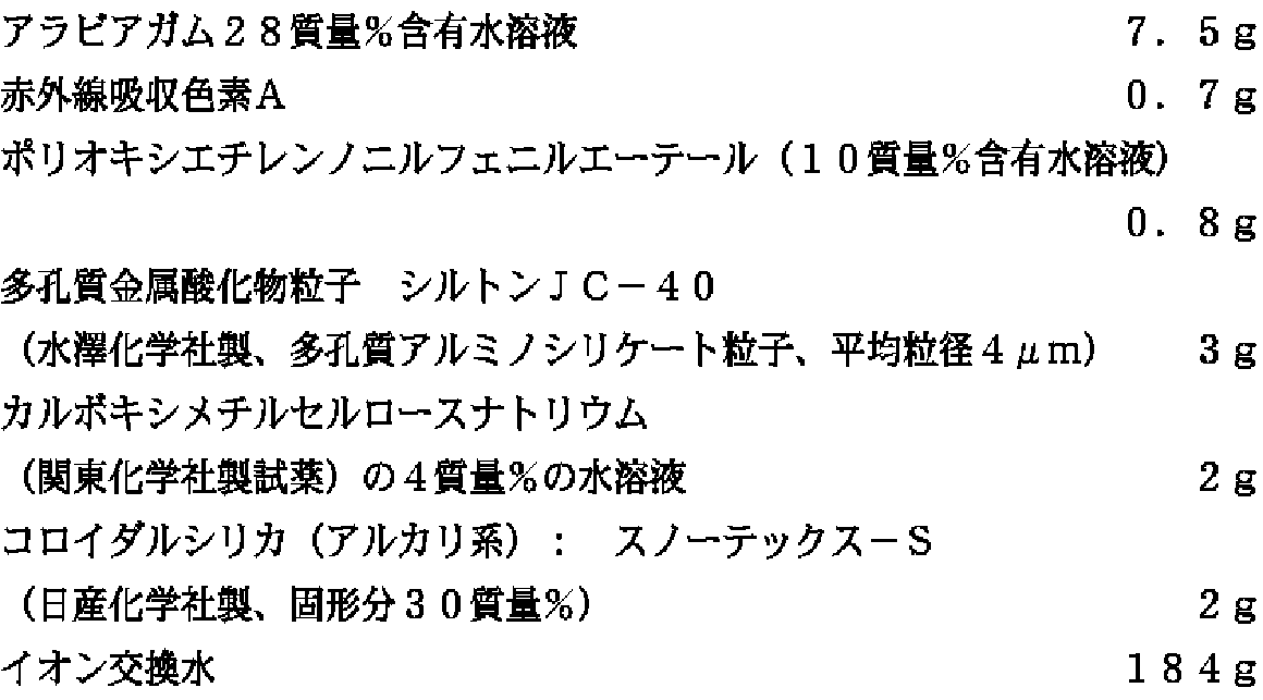
画像形成層の塗布
表3の組成を十分に混合攪拌した後、濾過して画像形成層用塗布液を作製した。表中単位記載のない数値は質量部を示す。
【0105】
【表3】
【化1】
表4に示した支持体と上記塗布液との組み合わせ各層をワイヤーバーで乾燥塗布質量1.5gになるように塗布して実施例および比較例の印刷版材料を作製した。画像形成層の乾燥条件は55℃3分間で行い、さらに55℃24時間のエイジングを行った。
【0108】
[オーバーコート層の塗布]
上記画像形成層上に、下記組成のオーバーコート層塗布液をワイヤーバーで塗布し、100℃90秒間乾燥して、乾燥塗布質量0.3g/m2のオーバーコート層を有する印刷版材料を作製した。さらに55℃24時間のエイジングを行った。
【0109】
(オーバーコート層塗布液)
画像形成は赤外線レーザー露光により行った。露光には波長830nm、スポット径約18μmのレーザービームを用い、レーザービームの焦点を印刷版材料表面に合わせて、露光エネルギーを300mj/cm2とした条件で、2400dpi(dpiとは1インチ、即ち2.54cm当たりのドット数を表す)、175線で画像を形成した。評価用の画像として、ベタ画像と1〜99%の網点画像を用いた。
【0110】
印刷性能の評価方法
上記で作製した試料で下記の印刷試験を行い、性能を評価した。結果を表4に示す。
【0111】
印刷方法
印刷機:三菱重工業(株)製DAIYA1F−1の版胴に印刷版材料を取り付け、コート紙、湿し水:アストロマーク3(日研化学研究所製)2質量%、インク(東洋インク(株)製トーヨーキングハイエコーM紅)を使用して印刷を行った。印刷開始のシークエンスはPS版の印刷シークエンスで行い、特別な機上現像操作は行わなかった。印刷後に版面を観察したところ、本発明に係る材料の非画像部は除去されていた。
【0112】
刷り出し性評価
刷り出し時、良好なS/N(非画像部に地汚れがなく、すなわち、画像形成層の非画像部が印刷機上で除去され、かつ、画像部の濃度が適正範囲となっている)を有した印刷物が得られるまでの印刷枚数を評価した。枚数が少ないほど優れている。40枚以上では実用上問題がある。
【0113】
耐刷性評価
3%網点画像の点が半分以上欠落する印刷枚数を求めた(印刷は10万枚まで行った)。印刷枚数の多いほど優れている。
【0114】
【表4】
表4から、本発明の試料は、刷り出し性、耐刷性に優れていることがわかる。実施例2
画像形成層を下記表5記載の塗布液組成3に、親水性オーバーコート層を塗布液組成4にする以外は実施例1と同様にして試料を作製した。
【0116】
【表5】
オーバーコート層塗布液組成4
上記で作製した試料を、保存性の代用条件として50℃80%の条件で3日間保管した。その試料を実施例1と同様の印刷試験を行い、性能を評価した。結果を表6に示す。
【0118】
【表6】
表6から、本発明の試料は、刷り出し性、耐刷性に優れていることがわかる。
実施例3
実施例2の試料番号201の印刷版を実施例1と同様に露光し(但し露光時に表7の操作を加えた)、露光後の下記の各タイミングで現像インクを用いて画像形成の状態をルーペを用いて評価した。結果を表7に示す。
【0120】
【表7】
表7から、露光終了後になんらかの乾燥過程を設けることで、画像強度が安定することがわかる。
【0122】
【発明の効果】
本発明により、印刷性能、特に刷り出し性や耐刷性が十分であり、画像形成前に印刷材料を長期に保存する場合に性能が変化しない印刷版材料及び印刷方法を提供することができた。
【図面の簡単な説明】
【図1】アルミニウム支持体の拡大断面図である。
【図2】図1の一部をさらに拡大した拡大断面図である。
【符号の説明】
1 小ピット
2 大きなうねり
d1 小ピット1の平均開孔径
h 小ピット1の平均深さ
d2 大きなうねり2の平均開孔径[0001]
BACKGROUND OF THE INVENTION
The present invention relates to a printing plate material and a printing method, and more particularly to a printing plate material capable of image formation by a computer-to-plate (CTP) method and a printing method in which image formation is performed by a CTP method.
[0002]
[Prior art]
With the digitization of print data, there is a need for CTPs that are inexpensive, easy to handle, and have the same printability as PS plates. In particular, in recent years, there is an increasing expectation for a so-called processless printing plate that does not require a developer treatment with a special chemical.
[0003]
Infrared laser recording is a promising image-forming method for processless printing plates. Broadly speaking, there are three types of recording: ablation type, thermal fusion image layer development type and thermal fusion transfer type, which will be described later. There is a method.
[0004]
Examples of the ablation type include those having a hydrophilic layer and a lipophilic layer on a support and laminating one of the layers as a surface layer (for example, see Patent Documents 1 to 6). If the surface layer is a hydrophilic layer, it is possible to form an image portion by exposing it like an image, ablating the hydrophilic layer and removing it like an image to expose the lipophilic layer. However, since the contamination inside the exposure apparatus due to the scattered material of the ablated surface layer becomes a problem, a water-soluble protective layer is further provided on the hydrophilic layer to prevent the ablated surface layer from scattering, and the protective layer on the printing press. A method for removing the ablated surface layer has also been proposed.
[0005]
Examples of the development type on the heat fusion image layer machine include a hydrophilic layer or an aluminum grain, and an image forming layer using thermoplastic fine particles and a water-soluble binder (for example, see Patent Document 7). It is done. However, when an aluminum grain is used as the hydrophilic support, it is necessary to add a photothermal conversion material (generally colored to visible light) to the image forming layer. As a layer structure, it is more advantageous to use a layer in which a hydrophilic layer containing a light-to-heat conversion material is formed on the support, and to remove the light-to-heat conversion material from the image forming layer. It is.
[0006]
In addition, as a heat-melt transfer type, for example, a heat transfer ribbon such as Manroland's DICO web is used, and an image-like heat-melting material is applied to a metal sleeve having a hydrophilic surface that can be used repeatedly instead of an aluminum grain. And a method of fixing the image by heating.
[0007]
However, these conventional technologies have insufficient printing performance, particularly ink fillability and printing durability, and have a drawback that the performance is likely to change when the printing material is stored for a long time before image formation. It was.
[0008]
[Patent Document 1]
JP-A-8-507727 (Claims, Examples)
[0009]
[Patent Document 2]
JP-A-6-186750 (Claims, Examples)
[0010]
[Patent Document 3]
JP-A-6-199064 (Claims, Examples)
[0011]
[Patent Document 4]
JP-A-7-314934 (Claims, Examples)
[0012]
[Patent Document 5]
JP-A-10-58636 (Claims, Examples)
[0013]
[Patent Document 6]
JP-A-10-244773 (Claims, Examples)
[0014]
[Patent Document 7]
Japanese Patent No. 2938397 (Claims, Examples)
[0015]
[Problems to be solved by the invention]
An object of the present invention is to provide a printing plate material and a printing method which have sufficient printing performance, particularly printing performance and printing durability, and whose performance does not change when the printing material is stored for a long time before image formation. is there.
[0016]
[Means for Solving the Problems]
The above object of the present invention has been achieved by the following constitutions.
[0017]
1. A printing plate material for use in a printing method comprising a step of forming an image on a printing plate material using a thermal head or a thermal laser and then removing a non-image portion of an image forming layer on a printing machine, the printing plate material Is Contains at least one kind of fine particles selected from heat-fusible fine particles and heat-fusible fine particles on an aluminum support that has been subjected to roughening treatment and anodizing treatment satisfying the following conditions (a) and (b) A printing plate material comprising an image forming layer.
Condition (a): It has a rough surface shape of a double structure in which small pits are superimposed on large undulations.
Condition (b): Average hole diameter d of small pits 1 (Μm) is 0.1 μm or more and 3 μm or less, the average depth h (μm) of the small pits and the average hole diameter d 1 (Μm) ratio h / d 1 Is 0.4 or less.
[0018]
2. After the aluminum support according to 1 is further treated with an alkali metal silicate, an image forming layer containing at least one kind of fine particles selected from heat-fusible fine particles and heat-fusible fine particles is formed on the aluminum support. A printing plate material characterized by being formed.
[0019]
3. 3. The printing plate material as described in 1 or 2 above, wherein a photothermal conversion material is contained on the support.
[0020]
4). 4. The printing plate material as described in any one of 1 to 3 above, wherein a hydrophilic overcoat layer is provided on the upper layer of the image forming layer.
[0022]
5 . The printing plate material according to any one of 1 to 4 above. The picture A printing method comprising a step of drying the surface of the printing plate material after the image formation until the surface of the printing plate material comes into contact with the water supply roller or the ink supply roller on the printing press.
[0023]
The present invention will be described in more detail.
Heat-meltable fine particles
The heat-meltable fine particles used in the present invention are fine particles formed of a material that has a low viscosity when melted, and is generally classified as a wax, among thermoplastic materials. The physical properties are preferably a softening point of 40 ° C. or higher and 120 ° C. or lower, a melting point of 60 ° C. or higher and 150 ° C. or lower, more preferably a softening point of 40 ° C. or higher and 100 ° C. or lower, and a melting point of 60 ° C. or higher and 120 ° C. or lower. When the melting point is less than 60 ° C., storage stability is a problem, and when the melting point is higher than 150 ° C., ink deposition sensitivity is lowered.
[0024]
Examples of usable materials include paraffin, polyolefin, polyethylene wax, microcrystalline wax, and fatty acid wax. These have a molecular weight of about 800 to 10,000, and in order to facilitate emulsification, these waxes can be oxidized to introduce polar groups such as hydroxyl group, ester group, carboxyl group, aldehyde group and peroxide group. Furthermore, in order to lower the softening point and improve workability, these waxes include, for example, stearoamide, linolenic amide, lauryl amide, myristyl amide, hardened bovine fatty acid amide, palmitoamide, oleic acid amide, rice sugar fatty acid amide, palm It is also possible to add fatty acid amides or methylolated products of these fatty acid amides, methylene bisstellaramide, ethylene bisstellaramide and the like. Coumarone-indene resin, rosin-modified phenol resin, terpene-modified phenol resin, xylene resin, ketone resin, acrylic resin, ionomer, and copolymers of these resins can also be used.
[0025]
Among these, it is preferable to contain any of polyethylene, microcrystalline, fatty acid ester, and fatty acid. Since these materials have a relatively low melting point and a low melt viscosity, high-sensitivity image formation can be performed. In addition, since these materials have lubricity, damage when a shearing force is applied to the surface of the printing plate material is reduced, and resistance to printing stains due to scratches or the like is improved.
[0026]
The heat-meltable fine particles are preferably dispersible in water, and the average particle size is preferably 0.01 to 10 μm, more preferably 0.1 to 3 μm. When the average particle size is smaller than 0.01 μm, when the coating liquid for the layer containing the heat-meltable fine particles is applied onto the porous hydrophilic layer described later, the heat-meltable fine particles are not removed from the pores of the hydrophilic layer. It becomes easy to enter inside or into the gaps between fine irregularities on the surface of the hydrophilic layer, and the on-press development becomes insufficient, which may cause scumming. When the average particle size of the heat-meltable fine particles is larger than 10 μm, the resolution is lowered.
[0027]
Further, the composition of the heat-meltable fine particles may vary continuously between the inside and the surface layer, or may be coated with a different material. As a coating method, a known microcapsule formation method, a sol-gel method, or the like can be used.
[0028]
As content of the heat-meltable microparticles | fine-particles in a structural layer, 1-90 mass% of the whole layer is preferable, and 5-80 mass% is more preferable.
[0029]
Thermally fusible particles
Examples of the heat-fusible fine particles that can also be used in the present invention include thermoplastic hydrophobic polymer fine particles, and there is no specific upper limit to the softening temperature of the thermoplastic hydrophobic polymer fine particles. Is preferably lower than the decomposition temperature of the polymer fine particles. The mass average molecular weight (Mw) of the polymer is preferably in the range of 10,000 to 1,000,000.
[0030]
Specific examples of the polymer constituting the polymer particles include, for example, diene (co) polymers such as polypropylene, polybutadiene, polyisoprene and ethylene-butadiene copolymer, styrene-butadiene copolymer, Synthetic rubbers such as methyl methacrylate-butadiene copolymer, acrylonitrile-butadiene copolymer, polymethyl methacrylate, methyl methacrylate- (2-ethylhexyl acrylate) copolymer, methyl methacrylate-methacrylic acid copolymer, methyl acrylate- ( N-methylolacrylamide) copolymer, (meth) acrylic acid ester such as polyacrylonitrile, (meth) acrylic acid (co) polymer, polyvinyl acetate, vinyl acetate-vinyl propionate copolymer, vinyl acetate-ethylene copolymer Vinyl etc. of polymers Ester (co) polymer, vinyl acetate - (2-ethylhexyl acrylate) copolymers, polyvinyl chloride, polyvinylidene chloride, polystyrene and copolymers thereof. Of these, (meth) acrylic acid esters, (meth) acrylic acid (co) polymers, vinyl ester (co) polymers, polystyrene, and synthetic rubbers are preferably used.
[0031]
The polymer polymer fine particles may be composed of a polymer polymer polymerized by any known method such as an emulsion polymerization method, a suspension polymerization method, a solution polymerization method, and a gas phase polymerization method. As a method of microparticulating a polymer polymer polymerized by a solution polymerization method or a gas phase polymerization method, a method of spraying a solution in an organic solvent of the polymer polymer into an inert gas and drying to form particles, Examples thereof include a method in which a high molecular weight polymer is dissolved in a water-immiscible organic solvent, this solution is dispersed in water or an aqueous medium, and the organic solvent is distilled off to form fine particles. In any of the methods, the heat-meltable fine particles and the heat-fusible fine particles may be used as a dispersant or a stabilizer, for example, when polymerized or finely divided, such as sodium lauryl sulfate, sodium dodecylbenzenesulfonate, polyethylene. A surfactant such as glycol or a water-soluble resin such as polyvinyl alcohol may be used. Further, triethylamine, triethanolamine or the like may be contained.
[0032]
The thermoplastic fine particles are preferably dispersible in water, and the average particle diameter is preferably 0.01 to 10 μm, more preferably 0.1 to 3 μm. When the average particle size is smaller than 0.01 μm, when the coating liquid for the layer containing the heat-meltable fine particles is applied onto the porous hydrophilic layer described later, the heat-meltable fine particles are not removed from the pores of the hydrophilic layer. It becomes easy to enter inside or into the gaps between fine irregularities on the surface of the hydrophilic layer, and the on-press development becomes insufficient, which may cause scumming. When the average particle size of the heat-meltable fine particles is larger than 10 μm, the resolution is lowered.
[0033]
The thermoplastic fine particles may be continuously changed in composition between the inside and the surface layer, or may be coated with different materials. As a coating method, a known microcapsule formation method, a sol-gel method, or the like can be used.
[0034]
As content of the thermoplastic fine particle in a structure layer, 1-90 mass% of the whole layer is preferable, and 5-80 mass% is further more preferable.
[0035]
Water-soluble material
The image forming layer containing the heat-fusible and / or heat-fusible fine particles according to the present invention can further contain a water-soluble material. By containing the water-soluble material, when the image forming layer in the unexposed area is removed using dampening water or ink on the printing press, the removability can be improved.
[0036]
As the water-soluble material, the water-soluble resins mentioned as materials that can be contained in the hydrophilic overcoat layer described later can be used. However, as the image forming layer of the present invention, it is preferable to use saccharides, particularly oligos. It is preferable to use sugar. Since the oligosaccharide quickly dissolves in water, the removal of the image forming layer in the unexposed area on the printing apparatus becomes very quick, and the normal PS plate printing operation can be performed without being aware of the special removal operation. It can be removed by printing in the same operation, and there is no increase in printing waste paper. In addition, the oligosaccharide can maintain good printability of the hydrophilic layer without concern for lowering the hydrophilicity of the hydrophilic layer. An oligosaccharide is a crystalline substance that is soluble in water and generally has a sweet taste, and is obtained by dehydrating and condensing several monosaccharides by glycosidic bonds. Oligosaccharide is a kind of o-glycoside with sugar as aglycone, so it is easily hydrolyzed with acid to produce monosaccharide, and disaccharide, trisaccharide, tetrasaccharide, pentasaccharide, etc. depending on the number of molecules of monosaccharide produced are categorized. The oligosaccharide in the present invention refers to those from disaccharide to decasaccharide.
[0037]
These oligosaccharides are roughly classified into reducing oligosaccharides and non-reducing oligosaccharides depending on the presence or absence of a reducing group, and also from homooligosaccharides composed of a single monosaccharide and two or more types of monosaccharides. It is also classified as a configured hetero-oligosaccharide. Oligosaccharides exist naturally as free or glycosides and can also be obtained by partial hydrolysis of polysaccharides with acids or enzymes. Various oligosaccharides are also generated by glycosyl transfer by other enzymes.
[0038]
Oligosaccharides often exist as hydrates in a normal atmosphere. In addition, hydrates and anhydrides have different melting points, and examples are as shown in Table 1.
[0039]
[Table 1]
In the present invention, it is preferable to coat and form a saccharide-containing layer with an aqueous solution. When formed from an aqueous solution, when the oligosaccharide present in the layer is an oligosaccharide that forms a hydrate, The melting point is considered to be that of the hydrate. Thus, since it has a relatively low melting point, the oligosaccharide also melts in the temperature range in which the hot melt fine particles melt or in the temperature range in which the hot melt fine particles fuse, and the porous hydrophilic layer of the hot melt fine particles It does not hinder image formation such as melt penetration into the film and fusion of heat-fused fine particles.
[0041]
Among oligosaccharides, trehalose is commercially available in a relatively high purity state at a low cost, and despite its high solubility in water, its hygroscopicity is very low, and on-press developability and The storage stability is very good.
[0042]
In addition, when oligosaccharide hydrate is melted by heat to remove water of hydration and then solidified (for a short time after solidification), it becomes an anhydrous crystal, but trehalose has a melting point of anhydride higher than that of hydrate. It is characteristic that it is higher than 100 ° C. This means that the exposed portion is melted by infrared exposure and immediately after re-solidification, the exposed portion is in a state of being difficult to melt at a high melting point, and is effective in causing image defects during exposure such as banding. In order to achieve the object of the present invention, trehalose is particularly preferable among oligosaccharides.
[0043]
As content of the oligosaccharide in a structure layer, 1-90 mass% of the whole layer is preferable, and 10-80 mass% is more preferable.
The image forming layer according to the present invention preferably contains a photothermal conversion material described later.
[0044]
The dry coating mass of the image forming layer is preferably 0.10 to 0.75 g / m. 2 , More preferably 0.15 to 0.50 g / m 2 It is.
[0045]
Hydrophilic overcoat layer
In the present invention, it is preferable to have a hydrophilic overcoat layer as an upper layer of the image forming layer. The hydrophilic overcoat layer may be a layer immediately above the image forming layer, or an intermediate layer may be provided between the image forming layer and the hydrophilic overcoat layer. The hydrophilic overcoat layer is preferably removable on a printing press.
[0046]
In the present invention, the hydrophilic overcoat layer preferably contains a water-soluble resin or a water-swellable resin obtained by partially crosslinking the water-soluble resin.
[0047]
Such a water-soluble resin is selected from water-soluble natural polymers and synthetic polymers, and is used together with a crosslinking agent, and a coated and dried film has a film-forming ability. Specific examples of water-soluble resins preferably used in the present invention include natural gums such as gum arabic, water-soluble soybean polysaccharides, fiber derivatives (for example, carboxymethyl cellulose, carboxyethyl cellulose, methyl cellulose, etc.), and modifications thereof. In the case of synthetic polymers such as body, white dextrin, pullulan, enzymatically decomposed etherified dextrin, polyvinyl alcohol (polyvinyl acetate having a hydrolysis rate of 65% or more), polyacrylic acid, its alkali metal salt or amine salt, polyacryl Acid copolymer, alkali metal salt or amine salt thereof, polymethacrylic acid, alkali metal salt or amine salt thereof, vinyl alcohol / acrylic acid copolymer and alkali metal salt or amine salt thereof, polyacrylamide, copolymer thereof, Polyhydroxyethyl acrylic , Polyvinyl pyrrolidone, copolymer thereof, polyvinyl methyl ether, vinyl methyl ether / maleic anhydride copolymer, poly-2-acrylamido-2-methyl-1-propanesulfonic acid, alkali metal salt or amine salt thereof, Examples thereof include poly-2-acrylamido-2-methyl-1-propanesulfonic acid copolymer, alkali metal salt or amine salt thereof. Further, two or more kinds of these resins can be mixed and used depending on the purpose. However, the present invention is not limited to these examples.
[0048]
When at least one or more of the water-soluble resins are partially crosslinked to form an overcoat layer on the hydrophilic layer, the crosslinking is performed by a crosslinking reaction using a reactive functional group possessed by the water-soluble resin. The crosslinking reaction may be a covalent bond or an ionic bond.
[0049]
Crosslinking reduces the adhesiveness of the overcoat layer surface and improves handling, but if the crosslinking proceeds too much, the overcoat layer changes to oleophilic, making it difficult to remove the overcoat layer on the printing press. Appropriate partial cross-linking is preferred. The preferred degree of partial crosslinking is that when the printing original plate is immersed in water at 25 ° C., the hydrophilic overcoat layer does not elute for 30 seconds to 10 minutes, but elution is observed after 10 minutes or more. Degree.
[0050]
Examples of the compound (crosslinking agent) used for the crosslinking reaction include known polyfunctional compounds having crosslinking properties, such as polyepoxy compounds, polyamine compounds, polyisocyanate compounds, silane compounds, titanate compounds, aldehyde compounds, polyvalent metals. Examples thereof include salt compounds and hydrazine. The crosslinking reaction can be accelerated by adding a known catalyst. Specific examples include the following compounds.
[0051]
Specific examples of polyepoxy compounds include glycerin polyglycidyl ether, polyethylene glycol diglycidyl ether, polypropylene glycol diglycidyl ether, trimethylolpropane polyglycidyl ether, trimethylolpropane polyglycidyl ether, sorbitol polyglycidyl ether, bisphenols or their And polycondensates of hydrogenated products and epihalohydrins.
[0052]
Specific examples of the polyamine compound include ethylenediamine, diethylenetriamine, triethylenetetramine, tetraethylenepentamine, hexamethylenediamine, propylenediamine, polyethyleneimine, and polyamidoamine.
[0053]
Specific examples of the polyisocyanate compound include tolylene diisocyanate, diphenylmethane isocyanate, liquid diphenylmethane diisocyanate, polymethylene polyphenyl isocyanate, xylylene diisocyanate, naphthalene-1,5-diisocyanate, cyclohexanephenylene diisocyanate, isopropylbenzene-2,4-diisocyanate. And the like, aliphatic isocyanates such as hexamethylene diisocyanate and decamethylene diisocyanate, alicyclic diisocyanates such as cyclohexyl diisocyanate and isophorone diisocyanate, and polypropylene glycol / tolylene diisocyanate addition reactants.
[0054]
As the silane compound, methyltrimethoxysilane, methyltriethoxysilane, ethyltriethoxysilane, phenyltriethoxysilane, vinyltriethoxysilane, γ-aminopropyltriethoxysilane, N- (β-aminoethyl) -γ-amino Propyltrimethoxysilane, γ-glycidoxypropyltrimethoxysilane, γ-methacryloxypropyltrimethoxysilane, γ-mercaptopropyltrimethoxysilane, β- (3,4-epoxycyclohexyl) ethyltrimethoxysilane, dimethyldimethoxysilane , Dimethyldiethoxysilane, diphenyldiethoxysilane, 3-chloropropylmethyldimethoxysilane, vinyltris (methylethylketoxime) silane, methyltris (methylethylketoxime) silane, Sulfonyl triacetoxy silane, and the like.
[0055]
Titanate compounds include tetraethylorthosilicate, bis (dioctylpyrophosphate) ethylene titanate, isopropyltoreactor noyl titanate, isopropyldimethacrylisostearoyl titanate, isopropylisostearoyldiacryl titanate, isopropyl (dioctylphosphate) titanate, isopropyltricumylphenyl titanate , Isopropyl tri (N-aminoethylaminoethyl) titanate, dicumylphenyloxyacetate titanate, diisostearoyl ethylene titanate, isopropyl triinstearoyl titanate, isopropyl tridodecylbenzenesulfonyl titanate, isopropyl tris (dioctyl phosphate) titanate, tetraisopropyl bis ( Octyl phosphite) titanate, tetraoctyl bis (ditridisyl phosphite) titanate, tetra (2,2-diallyloxymethyl-1-butyl) bis (ditridecyl phosphite titanate), bis (dioctyl pyrophosphate) oxyacetate titanate Bis (dioctylpyrophosphate) oxyacetate titanate, etc.
[0056]
Examples of aldehyde compounds include formaldehyde, acetaldehyde, propyl aldehyde, butyraldehyde, glyoxal, glutaraldehyde, terephthalaldehyde, and the like.
[0057]
Examples of the polyvalent metal salt compound include water-soluble salts of metals such as zinc, calcium, magnesium, barium, strontium, cobalt, manganese and nickel.
[0058]
These crosslinking agents can be used alone or in admixture of two or more. Among these cross-linking agents, a particularly preferable cross-linking agent is a water-soluble cross-linking agent, but a water-insoluble cross-linking agent can be used by being dispersed in water with a dispersant.
[0059]
Particularly preferred combinations of water-soluble resins and crosslinking agents include carboxylic acid-containing water-soluble resins / polyvalent metal compounds, carboxylic acid-containing water-soluble resins / water-soluble epoxy resins, and hydroxyl group-containing resins / dialdehydes.
[0060]
The suitable addition amount of a crosslinking agent is 2-10 mass% of water-soluble resin. Within this range, good water resistance can be obtained without impairing the removability of the overcoat layer on the printing press.
[0061]
In the present invention, the hydrophilic overcoat layer preferably contains a photothermal conversion material described later.
[0062]
In addition, a nonionic surfactant can be mainly added to the overcoat layer in the case of aqueous solution coating for the purpose of ensuring the uniformity of coating. Specific examples of such nonionic surfactants include sorbitan tristearate, sorbitan monopalmitate, sorbitan trioleate, stearic acid monoglyceride, polyoxyethylene nonylphenyl ether, polyoxyethylene dodecyl ether and the like. . The proportion of the nonionic surfactant in the overcoat layer in the total solid is preferably 0.05 to 5 mass%, more preferably 1 to 3 mass%.
[0063]
In the present invention, the dry coating amount of the overcoat layer is 0.1 to 0.4 g / m. 2 Is preferable, and a more preferable range is 0.15 to 0.25 g / m. 2 It is. Within this range, it is possible to satisfactorily prevent stains, prevent scratches, prevent fingerprint marks, and reduce ablation residue without impairing the removability of the overcoat layer on the printing press.
[0064]
Photothermal conversion material
The image forming layer according to the present invention, the hydrophilic layer, and the other layers can contain a photothermal conversion material.
[0065]
The following materials can be added as the photothermal conversion material.
(Infrared absorbing dye)
General infrared absorbing dyes such as cyanine dyes, croconium dyes, polymethine dyes, azurenium dyes, squalium dyes, thiopyrylium dyes, naphthoquinone dyes, anthraquinone dyes, organic compounds such as phthalocyanine dyes and naphthalocyanine dyes , Azo-based, thioamide-based, dithiol-based, and indoaniline-based organometallic complexes. Specifically, JP-A-63-139191, JP-A-64-33547, JP-A-1-160683, JP-A-1-280750, JP-A-1-293342, JP-A-2-2074, Kaihei 3-26593, JP-A-3-30991, JP-A-3-34891, JP-A-3-36093, JP-A-3-36094, JP-A-3-36095, JP-A-3-42281, JP-A-3-42281 Examples thereof include compounds described in JP-A-3-97589, JP-A-3-103476, and the like. These can be used alone or in combination of two or more.
[0066]
(Pigment)
Examples of the pigment include carbon, graphite, metal, metal oxide and the like. As carbon, it is particularly preferable to use furnace black or acetylene black. Particle size (d 50 ) Is preferably 100 nm or less, and more preferably 50 nm or less.
[0067]
(Graphite)
As the graphite, fine particles having a particle size of 0.5 μm or less, preferably 100 nm or less, more preferably 50 nm or less can be used.
[0068]
(metal)
As the metal, any metal can be used as long as the particle diameter is 0.5 μm or less, preferably 100 nm or less, more preferably 50 nm or less. The shape may be any shape such as a spherical shape, a piece shape, or a needle shape. Colloidal metal fine particles (Ag, Au, etc.) are particularly preferable.
[0069]
(Metal oxide)
As the metal oxide, a material that is black in the visible light region, or a material that has conductivity or is a semiconductor can be used. As the former, black iron oxide (Fe Three O Four ) And black composite metal oxides containing two or more of the aforementioned metals. Examples of the latter include SnO doped with Sb. 2 (ATO), In with Sn added 2 O Three (ITO), TiO 2 TiO 2 And TiO (titanium oxynitride, generally titanium black) reduced. These metal oxides can also be used as a core material (BaSO Four TiO 2 , 9Al 2 O Three ・ 2B 2 O, K 2 O · nTiO 2 Etc.) can also be used. These particle sizes are 0.5 μm or less, preferably 100 nm or less, and more preferably 50 nm or less.
[0070]
Among these photothermal conversion materials, black composite metal oxides containing two or more metals are more preferable materials, specifically, Al, Ti, Cr, Mn, Fe, Co, Ni, Cu, It is a composite metal oxide composed of two or more metals selected from Zn, Sb, and Ba. These are disclosed by methods disclosed in JP-A-8-27393, JP-A-9-25126, JP-A-9-237570, JP-A-9-241529, JP-A-10-231441, and the like. Can be manufactured.
[0071]
The composite metal oxide used in the present invention is particularly preferably a Cu-Cr-Mn-based or Cu-Fe-Mn-based composite metal oxide. In the case of a Cu—Cr—Mn system, it is preferable to perform the treatment disclosed in JP-A-8-27393 in order to reduce the elution of hexavalent chromium. These composite metal oxides are colored with respect to the amount added, that is, they have good photothermal conversion efficiency.
[0072]
These composite metal oxides preferably have an average primary particle diameter of 1 μm or less, and more preferably have an average primary particle diameter in the range of 0.01 to 0.5 μm. When the average primary particle size is 1 μm or less, the photothermal conversion ability with respect to the addition amount becomes better, and when the average primary particle size is within the range of 0.01 to 0.5 μm, the photothermal conversion ability with respect to the addition amount is better. It becomes. However, the photothermal conversion ability with respect to the addition amount is greatly affected by the degree of dispersion of the particles, and the better the dispersion, the better. Therefore, it is preferable to disperse these composite metal oxide particles by a known method separately before adding them to the layer coating solution to prepare a dispersion (paste). When the average primary particle size is less than 0.01, it is not preferable because dispersion becomes difficult. A dispersing agent can be appropriately used for the dispersion. The addition amount of the dispersant is preferably 0.01 to 5% by mass, and more preferably 0.1 to 2% by mass with respect to the composite metal oxide particles.
[0073]
As addition amount of these composite metal oxides, it is 0.1-50 mass% with respect to each layer, 1-30 mass% is preferable, and 3-25 mass% is more preferable.
[0074]
(Support)
The aluminum support used in the present invention is obtained from an aluminum support material using pure aluminum or an aluminum support material using an aluminum alloy. For the aluminum support material using the aluminum alloy, for example, an alloy of a metal such as silicon, copper, manganese, magnesium, chromium, zinc, lead, bismuth, nickel, titanium, sodium, iron, and aluminum is used. The surface of the aluminum support has a double rough surface shape in which small pits are superimposed on large undulations. 1 and 2 are enlarged sectional views showing an example of the aluminum support, and FIG. 2 is a further enlarged view of a part of FIG. 1 represents a small pit, 2 represents a large swell, d 1 (Μm) is the average hole diameter of the small pits 1, h (μm) is the average depth, d 2 (Μm) represents the average pore diameter of the large waviness 2. Average hole diameter d of small pits in the figure 1 (Μm) is 0.1 to 3 μm, the average depth h (μm) of the small pits and the average aperture diameter d 1 It is an essential requirement of the present invention that the ratio of (μm) is 0.4 or less. h / d 1 Is preferably 0.1 or more and 0.3 or less.
[0075]
Further, the average pore diameter d of large undulations on the surface of the aluminum support. 2 (Μm) is preferably more than 3 μm and not more than 20 μm. When the average pore diameter of the large waviness is out of the above range, fingerprint smudges easily occur.
[0076]
(Processing of support)
The above aluminum support material for obtaining an aluminum support is subjected to a dissolution treatment using an aqueous alkali solution such as caustic soda to remove strong dirt and a natural oxide film, and the residual alkali components after the dissolution treatment are removed. In order to neutralize, the neutralization treatment is performed by dipping in an acid such as phosphoric acid, nitric acid, sulfuric acid, hydrochloric acid, chromic acid or a mixed acid thereof. If necessary, in order to remove oil, rust, dust, etc. on the surface of the aluminum support material, a solvent degreasing treatment with trichlene, thinner or the like, or an emulsion degreasing treatment using an emulsion such as kerosene or triethanol may be performed.
[0077]
After the dissolution treatment using the alkaline aqueous solution and the neutralization treatment with the acid, the electrochemical roughening treatment described below is performed. The type and composition of the acid used for the neutralization treatment are changed to the electrochemical roughening treatment. It is particularly preferred to match that of the acid used.
[0078]
Prior to the dissolution treatment using the alkaline aqueous solution, a mechanical surface roughening treatment may be performed. The method of mechanical roughening treatment is not particularly limited, but brush polishing and honing polishing are preferable. In brush polishing, for example, a cylindrical brush in which a bristle having a bristle diameter of 0.2 to 1 mm is rotated and pressed against the surface of the aluminum support material while supplying a slurry in which abrasive is dispersed in water to the contact surface. Perform surface treatment. In the honing polishing, a slurry in which an abrasive is dispersed in water is injected by applying pressure from a nozzle, and the surface of the aluminum support material is collided obliquely to perform a roughening treatment. Furthermore, a mechanical roughening treatment can also be performed by pasting a roughened sheet on the surface of the aluminum support material and transferring a rough surface pattern by applying pressure.
[0079]
In addition, when performing the said mechanical surface roughening process, especially the said solvent degreasing process or an emulsion degreasing process can be abbreviate | omitted.
[0080]
After performing the above-mentioned (degreasing treatment if necessary) alkali dissolution treatment and neutralization treatment with an acid, the surface of the aluminum support material is subjected to an electrochemical surface roughening treatment using an alternating current in an acidic electrolyte. In the present invention, a rest period of 0.6 to 5 seconds is provided in the course of the electrochemical surface roughening treatment in the acidic electrolyte, and the amount of electricity in one electrochemical surface roughening treatment is 100 C / dm. 2 The following are essential requirements. When the electrochemical surface roughening treatment is performed in a plurality of times as described above, the pause time is less than 0.6 seconds, and the amount of electricity in one electrochemical surface roughening treatment is 100 C / dm. 2 If it exceeds 1, the formation of coarse pits with an opening diameter larger than 20 μm cannot be suppressed, and if the pause time exceeds 5 seconds, it takes too much time to produce the aluminum support, resulting in poor productivity.
[0081]
As the electrolytic solution for the electrochemical surface roughening treatment, hydrochloric acid, nitric acid or the like is used, and hydrochloric acid is more preferable. Nitrate, chloride, amines, aldehydes, phosphoric acid, chromic acid, boric acid, acetic acid, oxalic acid, and the like can be added to the electrolytic solution as necessary, but acetic acid is particularly preferable. 1-50V is preferable and, as for the voltage applied in an electrochemical roughening process, 5-30V is still more preferable. The current density (peak value) is 10 to 200 A / dm. 2 Is preferred, 20 to 150 A / dm 2 Is more preferable. The amount of electricity is 100 to 2000 C / dm in total for all processing steps. 2 Is preferable, 200-1000 C / dm 2 Is more preferable. The temperature is preferably 10 to 50 ° C, more preferably 15 to 45 ° C.
[0082]
The concentration of hydrochloric acid is preferably 0.1 to 5% by mass, and the current waveform used for electrolysis is appropriately selected depending on the roughened shape to be obtained, such as a sine wave, a rectangular wave, a trapezoidal wave, or a sawtooth wave. Waves are preferred. The aluminum substrate material that has been subjected to electrochemical surface roughening is immersed in an aqueous solution of acid or alkali to remove surface smut, etc., or to control the pit shape of the rough surface. Done. Examples of the acid include sulfuric acid, persulfuric acid, hydrofluoric acid, phosphoric acid, nitric acid, hydrochloric acid and the like, and examples of the alkali include sodium hydroxide and potassium hydroxide. Among these, it is preferable to use an aqueous solution of an alkali, and it is preferable to treat the solution with an aqueous solution of 0.05 to 40% of the alkali at a liquid temperature of 20 to 90 ° C. for 5 seconds to 5 minutes. After etching, neutralization is performed by immersing in an acid such as phosphoric acid, nitric acid, sulfuric acid, chromic acid, or a mixed acid thereof.
[0083]
The aluminum support material subjected to the neutralization treatment is further anodized to obtain the aluminum support of the present invention. Here, it is particularly preferable to match the type of acid used for neutralization with that of the acid used for anodizing treatment.
[0084]
The electrolytic solution used for the anodizing treatment may be any electrolytic solution as long as it forms a porous oxide film. Generally, sulfuric acid, phosphoric acid, oxalic acid, chromic acid, sulfamic acid, benzenesulfonic acid, etc. A mixed acid in which two or more of these are combined is used. The treatment conditions for anodization vary depending on the electrolytic solution used, and thus cannot be specified in general. In general, the concentration of the electrolytic solution is 1 to 80% by mass, the temperature is 5 to 70 ° C., and the current density is 1 to 1. 60A / dm 2 A voltage of 1 to 100 V and an electrolysis time of 10 seconds to 5 minutes are suitable. The sulfuric acid method is preferred, and the treatment is usually carried out with a direct current, but alternating current can also be used. Here, the concentration of sulfuric acid is 10 to 50% by mass, the temperature is 20 to 50 ° C., and the current density is 1 to 20 A / dm. 2 The electrolytic treatment is preferably carried out for 10 seconds to 5 minutes, and the electrolytic solution preferably contains aluminum ions.
[0085]
The aluminum support obtained by the anodizing treatment may be subjected to a sealing treatment as necessary. The sealing treatment can be performed using a known method such as hot water treatment, boiling water treatment, water vapor treatment, sodium silicate treatment, dichromate aqueous solution treatment, nitrite treatment, ammonium acetate treatment and the like. By these treatments, the conditions (a) and (b) of the present invention can be satisfied.
[0086]
A hydrophilic layer may be provided on the aluminum support obtained by the sealing treatment subsequent to the anodizing treatment or the anodizing treatment. For the formation of the hydrophilic layer, alkali metal silicates described in US Pat. No. 3,181,461, hydrophilic celluloses described in US Pat. No. 1,860,426, and Japanese Patent Publication No. 6-94234 are used. Amino acids and salts thereof described in JP-B-6-2436, amines having a hydroxyl group described in JP-B-5-32238, and salts thereof, and phosphates described in JP-A-62-19494 In addition, a polymer compound containing a monomer unit having a sulfo group described in JP-A No. 59-101651 can be used.
[0087]
Further, in order to prevent scratches on the photosensitive layer when a plurality of printing plates are stacked, and in order to prevent elution of the aluminum component in the developer during development, JP-A-50-151136 and JP-A-5-151136 Performing a treatment for providing a protective layer on the back surface of the support, as described in JP-A-57-63293, JP-A-60-73538, JP-A-61-67863, JP-A-6-35174, etc. Can do.
[0089]
Since image formation of the printing plate material of the present invention can be performed by heat, it is possible to form an image with a thermal head such as that used in a thermal printer, but it is particularly preferable to perform image formation by exposure with a thermal laser. .
[0090]
More specifically, exposure relating to the present invention is preferably scanning exposure using a laser that emits light in the infrared and / or near-infrared region, that is, in the wavelength range of 700 to 1500 nm. A gas laser may be used as the laser, but it is particularly preferable to use a semiconductor laser that emits light in the near infrared region.
[0091]
As an apparatus suitable for scanning exposure according to the present invention, any apparatus can be used as long as it can form an image on the surface of a printing plate material in accordance with an image signal from a computer using the semiconductor laser. Good.
[0092]
In general,
(1) A method of exposing the entire surface of the printing plate material by performing two-dimensional scanning using one or a plurality of laser beams on the printing plate material held by the plate-like holding mechanism,
(2) The circumferential direction of the cylinder (main scanning direction) using one or a plurality of laser beams from the inside of the cylinder to the printing plate material held along the cylindrical surface inside the fixed cylindrical holding mechanism ), Scanning the entire surface of the printing plate material by moving it in a direction perpendicular to the circumferential direction (sub-scanning direction),
(3) A printing plate material held on the surface of a cylindrical drum that rotates about an axis as a rotating body is rotated in the circumferential direction (main scanning direction) by rotating the drum using one or a plurality of laser beams from the outside of the cylinder. ) And moving in the direction perpendicular to the circumferential direction (sub-scanning direction) to expose the entire surface of the printing plate material.
[0093]
In the present invention, the scanning exposure method (3) is particularly preferable, and the exposure method (3) is used particularly in an apparatus that performs exposure on a printing apparatus.
[0094]
The printing plate material on which an image has been formed in this way can be printed without performing development processing. The printing plate material after image formation is attached to the plate cylinder of the printing machine as it is, or the printing plate material is attached to the plate cylinder of the printing machine, image formation is performed, and the water supply roller and / or ink supply is performed while rotating the plate cylinder The non-image portion of the image forming layer can be removed by bringing the roller into contact with the printing plate material.
[0095]
In the printing plate material of the present invention, the non-image portion removal step of the image forming layer can be performed in a normal printing sequence using a PS plate, so that it is not necessary to extend the working time by so-called on-press development processing. Therefore, it is effective for cost reduction.
[0096]
【Example】
Example 1
<Preparation of support>
A JIS1050 aluminum support material having a thickness of 0.24 mm was immersed in a 1% aqueous sodium hydroxide solution maintained at 50 ° C., and the dissolution amount was 2 g / m. 2 The solution was subjected to dissolution treatment and washed with water, then immersed in an aqueous solution having the same composition as the electrolytic solution used in the next electrochemical surface roughening treatment, neutralized, and then washed with water.
[0097]
The aluminum support material was then applied to a current density of 50 A / dm 2 Then, the electrochemical surface roughening treatment was performed using the sine wave alternating current under the conditions shown in Table 2 (electrolyte composition, amount of treatment electric power, number of times of electrolytic treatment, rest time). After the electrochemical surface roughening treatment, the surface was immersed in a 1% aqueous sodium hydroxide solution maintained at 50 ° C., and the dissolution amount was 2 g / m 2. 2 After being subjected to an alkali dissolution treatment so as to become, and further washed with water, it was immersed in a 10% sulfuric acid aqueous solution kept at 25 ° C. for 10 seconds for neutralization treatment, and then washed with water.
[0098]
Next, in 20% sulfuric acid aqueous solution, using direct current, temperature 25 ° C., current density 5 A / dm 2 The anodized film mass is 2.0 g / m 2 After anodizing so that it becomes, it was washed with water and dried to obtain 8 types of aluminum supports (supports 1 to 8). The average pore diameter d of the large waviness on the surface of the aluminum support thus obtained. 2 (Μm), average opening diameter d of small pits 1 (Μm), average depth h (μm) of small pits, and average aperture diameter d 1 (Μm) ratio h / d 1 Was measured by the method described later, and the results are shown in Table 2.
[0099]
Thereafter, the above supports 1 to 8 were treated with a 2.5% aqueous sodium silicate solution at 70 ° C. for 1 minute, washed with water and dried to obtain an aluminum support according to the present invention. The support 8 was not subjected to sodium silicate treatment.
[0100]
<Average pore diameter d of large undulations 2 (Μm), average opening diameter d of small pits 1 (Μm), average depth h (μm) of small pits, and average aperture diameter d 1 (Μm) ratio h / d 1 Measurement>
In either case, an SEM photograph of the aluminum support surface was taken and measured.
[0101]
Average swell diameter d 2 For (μm), a 1000 times SEM photograph was used to measure the major and minor diameters of each undulation whose contour could be clearly identified, and the average was taken as the undulating pore diameter, and was measured in the SEM photograph. The sum of the pore diameters of the large undulations was divided by the measured large undulation number. Also, the average opening diameter d of small pits 1 About (micrometer), it used for the method similar to the case of a big wave | undulation using 5000 times SEM photograph.
[0102]
Average depth h (μm) of small pits and average hole diameter d 1 (Μm) ratio h / d 1 Was measured using a SEM photograph having a cross section of 5000 to 20000 times, and selecting a pit having a cross section dividing almost the center of the pit.
[0103]
[Table 2]
Application of image forming layer
The compositions shown in Table 3 were sufficiently mixed and stirred, and then filtered to prepare an image forming layer coating solution. The numerical value without unit description in a table | surface shows a mass part.
[0105]
[Table 3]
[Chemical 1]
The respective combinations of the support shown in Table 4 and the above coating solution were applied with a wire bar so that the dry coating mass was 1.5 g, and printing plate materials of Examples and Comparative Examples were produced. The image forming layer was dried at 55 ° C. for 3 minutes, and further aged at 55 ° C. for 24 hours.
[0108]
[Application of overcoat layer]
On the image forming layer, an overcoat layer coating solution having the following composition was coated with a wire bar, dried at 100 ° C. for 90 seconds, and a dry coating mass of 0.3 g / m. 2 A printing plate material having an overcoat layer was prepared. Further, aging was performed at 55 ° C. for 24 hours.
[0109]
(Overcoat layer coating solution)
Image formation was performed by infrared laser exposure. For the exposure, a laser beam having a wavelength of 830 nm and a spot diameter of about 18 μm is used. The laser beam is focused on the surface of the printing plate material, and the exposure energy is 300 mj / cm. 2 Under these conditions, an image was formed with 2400 dpi (dpi represents 1 inch, that is, the number of dots per 2.54 cm) and 175 lines. As an image for evaluation, a solid image and a dot image of 1 to 99% were used.
[0110]
Evaluation method of printing performance
The following printing tests were performed on the samples prepared above, and the performance was evaluated. The results are shown in Table 4.
[0111]
Printing method
Printing machine: A printing plate material is attached to a plate cylinder of DAIYA1F-1 manufactured by Mitsubishi Heavy Industries, Ltd., coated paper, dampening water: 2% by mass of Astro Mark 3 (manufactured by Nikken Chemical Laboratory), ink (Toyo Ink Co., Ltd.) ) And Toyo King High Echo M Red). The printing start sequence was the PS printing sequence, and no special on-press development operation was performed. When the printing plate was observed after printing, the non-image area of the material according to the present invention was removed.
[0112]
Printability evaluation
Good S / N at the time of printing (the non-image area is free of background stain, that is, the non-image area of the image forming layer is removed on the printing machine, and the density of the image area is within an appropriate range) The number of printed sheets until a printed matter having a print quality was obtained was evaluated. The smaller the number, the better. There are practical problems with 40 sheets or more.
[0113]
Evaluation of printing durability
The number of printed sheets in which more than half of the dots in the 3% halftone image were missing was obtained (printing was performed up to 100,000 sheets). The higher the number of prints, the better.
[0114]
[Table 4]
From Table 4, it can be seen that the sample of the present invention is excellent in printing performance and printing durability. Example 2
A sample was prepared in the same manner as in Example 1 except that the image forming layer was changed to coating solution composition 3 shown in Table 5 below and the hydrophilic overcoat layer was changed to coating solution composition 4.
[0116]
[Table 5]
Overcoat layer coating solution composition 4
The sample prepared above was stored for 3 days under conditions of 50 ° C. and 80% as substitute conditions for storage stability. The sample was subjected to the same printing test as in Example 1 to evaluate the performance. The results are shown in Table 6.
[0118]
[Table 6]
From Table 6, it can be seen that the sample of the present invention is excellent in printing performance and printing durability.
Example 3
The printing plate of Sample No. 201 in Example 2 was exposed in the same manner as in Example 1 (however, the operations shown in Table 7 were added at the time of exposure). Evaluation was performed using a loupe. The results are shown in Table 7.
[0120]
[Table 7]
From Table 7, it can be seen that the image intensity is stabilized by providing some drying process after the exposure.
[0122]
【The invention's effect】
According to the present invention, it is possible to provide a printing plate material and a printing method which have sufficient printing performance, particularly printing performance and printing durability, and whose performance does not change when the printing material is stored for a long time before image formation. .
[Brief description of the drawings]
FIG. 1 is an enlarged cross-sectional view of an aluminum support.
FIG. 2 is an enlarged cross-sectional view in which a part of FIG. 1 is further enlarged.
[Explanation of symbols]
1 Small pit
2 Big swell
d 1 Average hole diameter of small pit 1
h Average depth of small pit 1
d 2 Average hole diameter of large swell 2
Claims (5)
条件(a):大きなうねりに小ピットが重畳された二重構造の粗面形状を有する。
条件(b):小ピットの平均開孔径d1(μm)が0.1μm以上3μm以下で、小ピットの平均深さh(μm)と該平均開孔径d1(μm)の比h/d1が0.4以下である。 A printing plate material for use in a printing method comprising a step of forming an image on a printing plate material using a thermal head or a thermal laser and then removing a non-image portion of an image forming layer on a printing machine, the printing plate material Is at least one kind of fine particles selected from heat fusible fine particles and heat fusible fine particles on an aluminum support that has been subjected to roughening treatment and anodizing treatment satisfying the following conditions (a) and (b): A printing plate material comprising an image forming layer containing
Condition (a): It has a rough surface shape of a double structure in which small pits are superimposed on large undulations.
Condition (b): The average hole diameter d 1 (μm) of the small pit is 0.1 μm or more and 3 μm or less, and the ratio h / d between the average depth h (μm) of the small pit and the average hole diameter d 1 (μm) 1 is 0.4 or less.
Priority Applications (4)
| Application Number | Priority Date | Filing Date | Title |
|---|---|---|---|
| JP2002274781A JP4100112B2 (en) | 2002-09-20 | 2002-09-20 | Printing plate material and printing method |
| US10/655,103 US20040055490A1 (en) | 2002-09-20 | 2003-09-03 | Printing plate precursor and printing method |
| DE60310658T DE60310658D1 (en) | 2002-09-20 | 2003-09-12 | Printing plate precursor and printing process |
| EP03020786A EP1400352B1 (en) | 2002-09-20 | 2003-09-12 | Printing plate precursor and printing method |
Applications Claiming Priority (1)
| Application Number | Priority Date | Filing Date | Title |
|---|---|---|---|
| JP2002274781A JP4100112B2 (en) | 2002-09-20 | 2002-09-20 | Printing plate material and printing method |
Publications (2)
| Publication Number | Publication Date |
|---|---|
| JP2004106446A JP2004106446A (en) | 2004-04-08 |
| JP4100112B2 true JP4100112B2 (en) | 2008-06-11 |
Family
ID=31944598
Family Applications (1)
| Application Number | Title | Priority Date | Filing Date |
|---|---|---|---|
| JP2002274781A Expired - Fee Related JP4100112B2 (en) | 2002-09-20 | 2002-09-20 | Printing plate material and printing method |
Country Status (4)
| Country | Link |
|---|---|
| US (1) | US20040055490A1 (en) |
| EP (1) | EP1400352B1 (en) |
| JP (1) | JP4100112B2 (en) |
| DE (1) | DE60310658D1 (en) |
Families Citing this family (9)
| Publication number | Priority date | Publication date | Assignee | Title |
|---|---|---|---|---|
| JP2004122363A (en) * | 2002-09-30 | 2004-04-22 | Konica Minolta Holdings Inc | Printing plate material and imaging method |
| US6912956B2 (en) * | 2002-11-01 | 2005-07-05 | Konica Minolta Holdings, Inc. | Printing plate material |
| JP2004188848A (en) * | 2002-12-12 | 2004-07-08 | Konica Minolta Holdings Inc | Print plate material |
| JP2005200683A (en) * | 2004-01-14 | 2005-07-28 | Konica Minolta Medical & Graphic Inc | Aluminum support for lithographic printing plate, its production method, lithographic printing plate material, and image forming method |
| JP2005231047A (en) * | 2004-02-17 | 2005-09-02 | Konica Minolta Medical & Graphic Inc | Method for manufacturing aluminum support for lithographic printing plate, aluminum support for lithographic printing plate and lithographic printing plate material/image forming method |
| US20070144384A1 (en) * | 2004-05-19 | 2007-06-28 | Fuji Photo Film Co., Ltd | Image recording method |
| EP1974912A1 (en) * | 2007-03-30 | 2008-10-01 | Agfa Graphics N.V. | A method for making a lithographic printing plate precursor. |
| EP3677434B1 (en) * | 2017-08-31 | 2022-10-19 | FUJIFILM Corporation | Lithographic printing original plate and method for producing lithographic printing plate |
| US12441895B2 (en) | 2022-09-02 | 2025-10-14 | KopMan LLC | Method and system for treating equipment surface |
Family Cites Families (21)
| Publication number | Priority date | Publication date | Assignee | Title |
|---|---|---|---|---|
| US3852091A (en) * | 1971-01-25 | 1974-12-03 | Columbia Ribbon Carbon Mfg | Thermographic transfer sheets |
| US3751318A (en) * | 1971-01-25 | 1973-08-07 | Columbia Ribbon Carbon Mfg | Thermographic transfer process |
| JP2681699B2 (en) | 1989-09-18 | 1997-11-26 | コニカ株式会社 | Metal-containing indoaniline compounds |
| US5379698A (en) | 1992-07-20 | 1995-01-10 | Presstek, Inc. | Lithographic printing members for use with laser-discharge imaging |
| AU674518B2 (en) | 1992-07-20 | 1997-01-02 | Presstek, Inc. | Lithographic printing plates for use with laser-discharge imaging apparatus |
| US5351617A (en) | 1992-07-20 | 1994-10-04 | Presstek, Inc. | Method for laser-discharge imaging a printing plate |
| JP2592225B2 (en) | 1993-02-09 | 1997-03-19 | アグフア−ゲヴエルト・ナームローゼ・フエンノートシヤツプ | Heat mode recording material and method for producing lithographic printing plate using the same |
| JP3342776B2 (en) * | 1994-08-30 | 2002-11-11 | 富士写真フイルム株式会社 | Aluminum support for lithographic printing plate, method for producing the same, and method for roughening aluminum support |
| US6344131B1 (en) * | 1994-08-30 | 2002-02-05 | Fuji Photo Film Co., Ltd. | Method of producing aluminum support for planographic printing plate |
| JPH1058636A (en) | 1996-08-20 | 1998-03-03 | Toray Ind Inc | Original plate for laser-sensitive lithographic plate |
| JPH10244773A (en) | 1997-03-05 | 1998-09-14 | Mitsubishi Chem Corp | Laser direct dampening water-free photosensitive lithographic printing plate |
| JP3622170B2 (en) * | 1997-09-26 | 2005-02-23 | コニカミノルタホールディングス株式会社 | Method for producing lithographic printing plate support and photosensitive lithographic printing plate |
| US6399270B1 (en) * | 1998-12-04 | 2002-06-04 | Konica Corporation | Support for printing plate and printing plate |
| JP2001334766A (en) * | 2000-05-30 | 2001-12-04 | Konica Corp | Planographic original plate and manufacturing method for the same |
| JP2002211098A (en) * | 2001-01-16 | 2002-07-31 | Konica Corp | Method and apparatus for printing |
| JP2002225411A (en) * | 2001-01-30 | 2002-08-14 | Konica Corp | Printing method and printing equipment |
| US7118848B2 (en) * | 2001-04-03 | 2006-10-10 | Fuji Photo Film Co., Ltd. | Support for lithographic printing plate and original forme for lithographic printing plate |
| US6692890B2 (en) * | 2001-04-04 | 2004-02-17 | Kodak Polychrome Graphics Llc | Substrate improvements for thermally imageable composition and methods of preparation |
| DE60215413T2 (en) * | 2001-04-09 | 2007-08-30 | Fuji Photo Film Co., Ltd., Minami-Ashigara | Lithographic printing plate precursor |
| DE60224229T2 (en) * | 2001-07-23 | 2008-12-11 | Fujifilm Corp. | Precursor for a lithographic printing plate |
| ATE541709T1 (en) * | 2001-10-05 | 2012-02-15 | Fujifilm Corp | LITHOGRAPHIC PRINTING PLATE SUBSTRATE AND PRESENSITIZED PLATE AND PROCESS FOR PRODUCTION OF A LITHOGRAPHIC PRINTING PLATE |
-
2002
- 2002-09-20 JP JP2002274781A patent/JP4100112B2/en not_active Expired - Fee Related
-
2003
- 2003-09-03 US US10/655,103 patent/US20040055490A1/en not_active Abandoned
- 2003-09-12 DE DE60310658T patent/DE60310658D1/en not_active Expired - Lifetime
- 2003-09-12 EP EP03020786A patent/EP1400352B1/en not_active Expired - Lifetime
Also Published As
| Publication number | Publication date |
|---|---|
| EP1400352B1 (en) | 2006-12-27 |
| JP2004106446A (en) | 2004-04-08 |
| EP1400352A3 (en) | 2005-02-02 |
| DE60310658D1 (en) | 2007-02-08 |
| EP1400352A2 (en) | 2004-03-24 |
| US20040055490A1 (en) | 2004-03-25 |
Similar Documents
| Publication | Publication Date | Title |
|---|---|---|
| JP2009101694A (en) | Printing plate material | |
| JPWO2007145048A1 (en) | Lithographic printing plate, lithographic printing plate material, lithographic printing plate support and lithographic printing method | |
| JP4100112B2 (en) | Printing plate material and printing method | |
| JPWO2008084645A1 (en) | Printing plate material | |
| JP2005169642A (en) | Printing plate material and method for manufacturing printing plate material | |
| JP4127954B2 (en) | Heat sensitive planographic printing plate | |
| JP4127951B2 (en) | Heat sensitive planographic printing plate | |
| JP4127953B2 (en) | Heat sensitive lithographic printing plate | |
| JP2007160668A (en) | Lithographic printing plate material, its manufacturing method and printing method | |
| JP2004174980A (en) | Printing plate material and printing plate | |
| JP4306257B2 (en) | Printing plate material and printing method | |
| JP2002086950A (en) | Original plate for heat sensitive lithographic printing plate | |
| JP2009000896A (en) | Lithographic printing plate material, aluminum support body, and method of manufacturing lithographic printing plate material | |
| JP2004160715A (en) | Printing plate material and printing plate | |
| JPWO2007074634A1 (en) | Support for printing plate material and printing plate material | |
| JP2007185829A (en) | Lithographic printing plate material, manufacturing method thereof and printing method | |
| JP3830139B2 (en) | Lithographic printing plate correction fluid and correction method | |
| JP2005297232A (en) | Printing plate material laminate, printing plate and printing method | |
| JP2009090621A (en) | Method for correcting lithographic printing plate and lithographic printing plate material | |
| JP2001162963A (en) | Positive type heat sensitive lithographic printing original plate | |
| JP2004230875A (en) | Printing plate material and printing plate | |
| JP2005111822A (en) | Printing method | |
| JP2004098376A (en) | Material for printing plate and printing method | |
| JP2004223723A (en) | Printing plate material and printing plate | |
| JP2007290148A (en) | Printing plate material |
Legal Events
| Date | Code | Title | Description |
|---|---|---|---|
| A621 | Written request for application examination |
Free format text: JAPANESE INTERMEDIATE CODE: A621 Effective date: 20050902 |
|
| A977 | Report on retrieval |
Free format text: JAPANESE INTERMEDIATE CODE: A971007 Effective date: 20071207 |
|
| A131 | Notification of reasons for refusal |
Free format text: JAPANESE INTERMEDIATE CODE: A131 Effective date: 20071225 |
|
| A521 | Written amendment |
Free format text: JAPANESE INTERMEDIATE CODE: A523 Effective date: 20080206 |
|
| TRDD | Decision of grant or rejection written | ||
| A01 | Written decision to grant a patent or to grant a registration (utility model) |
Free format text: JAPANESE INTERMEDIATE CODE: A01 Effective date: 20080226 |
|
| A61 | First payment of annual fees (during grant procedure) |
Free format text: JAPANESE INTERMEDIATE CODE: A61 Effective date: 20080310 |
|
| FPAY | Renewal fee payment (event date is renewal date of database) |
Free format text: PAYMENT UNTIL: 20110328 Year of fee payment: 3 |
|
| R150 | Certificate of patent or registration of utility model |
Ref document number: 4100112 Country of ref document: JP Free format text: JAPANESE INTERMEDIATE CODE: R150 Free format text: JAPANESE INTERMEDIATE CODE: R150 |
|
| FPAY | Renewal fee payment (event date is renewal date of database) |
Free format text: PAYMENT UNTIL: 20120328 Year of fee payment: 4 |
|
| FPAY | Renewal fee payment (event date is renewal date of database) |
Free format text: PAYMENT UNTIL: 20130328 Year of fee payment: 5 |
|
| FPAY | Renewal fee payment (event date is renewal date of database) |
Free format text: PAYMENT UNTIL: 20140328 Year of fee payment: 6 |
|
| S531 | Written request for registration of change of domicile |
Free format text: JAPANESE INTERMEDIATE CODE: R313531 |
|
| S533 | Written request for registration of change of name |
Free format text: JAPANESE INTERMEDIATE CODE: R313533 |
|
| R350 | Written notification of registration of transfer |
Free format text: JAPANESE INTERMEDIATE CODE: R350 |
|
| LAPS | Cancellation because of no payment of annual fees |