JP4099191B2 - Channel estimation apparatus and channel estimation method - Google Patents
Channel estimation apparatus and channel estimation method Download PDFInfo
- Publication number
- JP4099191B2 JP4099191B2 JP2005500860A JP2005500860A JP4099191B2 JP 4099191 B2 JP4099191 B2 JP 4099191B2 JP 2005500860 A JP2005500860 A JP 2005500860A JP 2005500860 A JP2005500860 A JP 2005500860A JP 4099191 B2 JP4099191 B2 JP 4099191B2
- Authority
- JP
- Japan
- Prior art keywords
- channel
- signal
- pilot
- estimated
- estimation
- Prior art date
- Legal status (The legal status is an assumption and is not a legal conclusion. Google has not performed a legal analysis and makes no representation as to the accuracy of the status listed.)
- Expired - Lifetime
Links
- 238000000034 method Methods 0.000 title claims description 99
- 230000005540 biological transmission Effects 0.000 claims description 74
- 230000004044 response Effects 0.000 claims description 51
- 238000012545 processing Methods 0.000 claims description 31
- 238000004364 calculation method Methods 0.000 claims description 24
- 230000008569 process Effects 0.000 claims description 19
- 238000004422 calculation algorithm Methods 0.000 claims description 18
- 238000006243 chemical reaction Methods 0.000 claims description 18
- 238000012546 transfer Methods 0.000 claims description 12
- 230000010363 phase shift Effects 0.000 claims description 11
- 230000009466 transformation Effects 0.000 claims description 7
- 239000000284 extract Substances 0.000 claims description 6
- 238000004590 computer program Methods 0.000 claims description 5
- 230000000694 effects Effects 0.000 claims description 3
- 230000000875 corresponding effect Effects 0.000 description 73
- 238000004891 communication Methods 0.000 description 40
- 239000011159 matrix material Substances 0.000 description 29
- 238000012549 training Methods 0.000 description 12
- 238000010586 diagram Methods 0.000 description 7
- 238000001914 filtration Methods 0.000 description 7
- 238000005070 sampling Methods 0.000 description 5
- 238000005516 engineering process Methods 0.000 description 4
- 238000007476 Maximum Likelihood Methods 0.000 description 3
- 238000010295 mobile communication Methods 0.000 description 3
- 230000002411 adverse Effects 0.000 description 2
- 238000000354 decomposition reaction Methods 0.000 description 2
- 238000005562 fading Methods 0.000 description 2
- 238000000926 separation method Methods 0.000 description 2
- 238000012935 Averaging Methods 0.000 description 1
- 108010003272 Hyaluronate lyase Proteins 0.000 description 1
- 230000001174 ascending effect Effects 0.000 description 1
- 230000008901 benefit Effects 0.000 description 1
- 230000001427 coherent effect Effects 0.000 description 1
- 239000002131 composite material Substances 0.000 description 1
- 230000001276 controlling effect Effects 0.000 description 1
- 238000007796 conventional method Methods 0.000 description 1
- 230000002596 correlated effect Effects 0.000 description 1
- 238000009792 diffusion process Methods 0.000 description 1
- 238000000605 extraction Methods 0.000 description 1
- 230000006872 improvement Effects 0.000 description 1
- 230000007246 mechanism Effects 0.000 description 1
- 230000000116 mitigating effect Effects 0.000 description 1
- 230000004048 modification Effects 0.000 description 1
- 238000012986 modification Methods 0.000 description 1
- 230000000737 periodic effect Effects 0.000 description 1
- 238000001228 spectrum Methods 0.000 description 1
- 238000010561 standard procedure Methods 0.000 description 1
Images
Classifications
-
- H—ELECTRICITY
- H04—ELECTRIC COMMUNICATION TECHNIQUE
- H04L—TRANSMISSION OF DIGITAL INFORMATION, e.g. TELEGRAPHIC COMMUNICATION
- H04L1/00—Arrangements for detecting or preventing errors in the information received
- H04L1/02—Arrangements for detecting or preventing errors in the information received by diversity reception
- H04L1/06—Arrangements for detecting or preventing errors in the information received by diversity reception using space diversity
-
- H—ELECTRICITY
- H04—ELECTRIC COMMUNICATION TECHNIQUE
- H04L—TRANSMISSION OF DIGITAL INFORMATION, e.g. TELEGRAPHIC COMMUNICATION
- H04L25/00—Baseband systems
- H04L25/02—Details ; arrangements for supplying electrical power along data transmission lines
- H04L25/0202—Channel estimation
- H04L25/0204—Channel estimation of multiple channels
-
- H—ELECTRICITY
- H04—ELECTRIC COMMUNICATION TECHNIQUE
- H04L—TRANSMISSION OF DIGITAL INFORMATION, e.g. TELEGRAPHIC COMMUNICATION
- H04L25/00—Baseband systems
- H04L25/02—Details ; arrangements for supplying electrical power along data transmission lines
- H04L25/0202—Channel estimation
- H04L25/022—Channel estimation of frequency response
-
- H—ELECTRICITY
- H04—ELECTRIC COMMUNICATION TECHNIQUE
- H04L—TRANSMISSION OF DIGITAL INFORMATION, e.g. TELEGRAPHIC COMMUNICATION
- H04L25/00—Baseband systems
- H04L25/02—Details ; arrangements for supplying electrical power along data transmission lines
- H04L25/0202—Channel estimation
- H04L25/0224—Channel estimation using sounding signals
-
- H—ELECTRICITY
- H04—ELECTRIC COMMUNICATION TECHNIQUE
- H04L—TRANSMISSION OF DIGITAL INFORMATION, e.g. TELEGRAPHIC COMMUNICATION
- H04L25/00—Baseband systems
- H04L25/02—Details ; arrangements for supplying electrical power along data transmission lines
- H04L25/0202—Channel estimation
- H04L25/024—Channel estimation channel estimation algorithms
-
- H—ELECTRICITY
- H04—ELECTRIC COMMUNICATION TECHNIQUE
- H04L—TRANSMISSION OF DIGITAL INFORMATION, e.g. TELEGRAPHIC COMMUNICATION
- H04L27/00—Modulated-carrier systems
- H04L27/26—Systems using multi-frequency codes
- H04L27/2601—Multicarrier modulation systems
- H04L27/2647—Arrangements specific to the receiver only
Landscapes
- Engineering & Computer Science (AREA)
- Computer Networks & Wireless Communication (AREA)
- Signal Processing (AREA)
- Power Engineering (AREA)
- Radio Transmission System (AREA)
Description
本発明は通信の分野に属し、特に、1つ以上の通信アンテナから送信された信号が受信機によって受信されるような、複数の入力経路が存在する環境におけるチャネル推定技術に関する。 The present invention belongs to the field of communication, and particularly relates to a channel estimation technique in an environment where a plurality of input paths exist such that a signal transmitted from one or more communication antennas is received by a receiver.
今日の移動無線通信技術においては、高いデータレートの実現が要求されており、この要求は今後、着実に強まていくものと予想される。このため、利用可能な帯域幅(換言すればチャネル容量)を効率的に使用することが求められている。このような状況の下、近年、複数の入出力経路を有する送受信システム(multiple input multiple output; MIMO)に顕著な進歩がみられている。MIMOシステムにおいては、各々1つの送信アンテナを有する複数の送信地点と、各々1つの受信アンテナを有する複数の受信地点とが使用され、複数の送信地点から送信された信号を複数の通信チャネルを用いて受信する。MIMOの技術においては、複数の送信アンテナから送信された信号を分離する必要があり、空間・時間符号化多重化法または空間多重化法が用いられる。 In today's mobile radio communication technology, it is required to realize a high data rate, and this requirement is expected to increase steadily in the future. For this reason, it is required to efficiently use available bandwidth (in other words, channel capacity). Under such circumstances, in recent years, remarkable progress has been made in a transmission / reception system (multiple input multiple output; MIMO) having a plurality of input / output paths. In a MIMO system, a plurality of transmission points each having one transmission antenna and a plurality of reception points each having one reception antenna are used, and signals transmitted from the plurality of transmission points are used by a plurality of communication channels. Receive. In the MIMO technique, it is necessary to separate signals transmitted from a plurality of transmission antennas, and a space / time coding multiplexing method or a space multiplexing method is used.
ここで、各受信アンテナに到達する信号は、NT個の送信地点から送信された信号の重ね合わせである。このことは、チャネル推定が困難になることを意味する。受信データを処理するためには、チャネルインパルス応答やチャネル伝達関数といったチャネルパラメータが必要となる。それぞれの送信地点において送信アンテナから送信された対応する信号を分離するのは困難な作業であるものの、各信号の間に相関がない限り、1つの受信アンテナを有する受信機を用いたシステムを、複数の受信アンテナを有するシステムへ拡張する作業は容易である。チャネル推定ユニットの構造は、受信アンテナの数NRに依存しない。複数入力単一出力(MISO)システムからMIMOシステムへ拡張するには、各々1つの受信地点(受信アンテナ)に対応する計NR個の並列のチャネル推定ユニットを用いる。 Here, the signal reaching each receiving antenna is a superposition of signals transmitted from N T transmission points. This means that channel estimation becomes difficult. In order to process received data, channel parameters such as channel impulse response and channel transfer function are required. Although it is a difficult task to separate the corresponding signals transmitted from the transmitting antenna at each transmission point, unless there is a correlation between the signals, a system using a receiver having one receiving antenna, The task of extending to a system having a plurality of receiving antennas is easy. The structure of the channel estimation unit does not depend on the number N R of reception antennas. In order to expand from a multiple input single output (MISO) system to a MIMO system, a total of N R parallel channel estimation units each corresponding to one reception point (receive antenna) are used.
無線通信システムにおける統一的な技術を採用しようとすれば、移動無線チャネルの推定および追跡(トラッキング)を行なう必要がある。複数の送信アンテナから送信された信号には相互干渉が観測されるから、MIMOシステムにおけるチャネル推定は、単一の送信アンテナを用いたシステムとはその取り扱いが異なる。MIMOシステムにおいては、移動無線通信システムの通信容量および通信品質の向上を図るため、複数キャリア変調方式を用いることができる。この複数キャリア変調技術の代表的なものとしては、直交周波数分割多重法(OFDM)がある。 If it is going to employ | adopt the unified technique in a radio | wireless communications system, it is necessary to perform estimation and tracking (tracking) of a mobile radio channel. Since mutual interference is observed in signals transmitted from a plurality of transmission antennas, channel estimation in a MIMO system is handled differently from a system using a single transmission antenna. In a MIMO system, a multi-carrier modulation scheme can be used in order to improve the communication capacity and communication quality of a mobile radio communication system. A representative example of the multicarrier modulation technique is orthogonal frequency division multiplexing (OFDM).
特定の直交周波数分割多重法(OFDM)における複数キャリア変調は、過去数年にわたり様々なデジタル通信システムに適用されてきた。特に、例えばデジタルTV等の高データレートの送信においては、分散チャネルを用いた送信におけるOFDMの優秀性は大きな武器である。このように、OFDMは、種々のデジタル放送標準(例えばDABやDVB−T)に採用されている。OFDMのその他の適用例としては、高速無線ローカルエリアネットワーク(WLAN)がある。 Multiple carrier modulation in certain orthogonal frequency division multiplexing (OFDM) has been applied to various digital communication systems over the past few years. In particular, in high data rate transmission such as digital TV, the superiority of OFDM in transmission using a distributed channel is a great weapon. Thus, OFDM is adopted in various digital broadcasting standards (for example, DAB and DVB-T). Other applications of OFDM include high speed wireless local area networks (WLANs).
OFDMが最初に登場したのは1960年代である。離散フーリエ変換(DFT)を用いた効率的な復調方法がS. WeinsteinおよびP. Ebertによって提唱された(非特許文献1参照)。チャネルの最大遅延よりも大きな値の周期的なプレフィックスをガードインターバル(GI)に挿入することにより、受信信号の直交性を保ちつつシンボル間干渉(ISI)を完全に除去することが可能となった。将来の移動通信システムは、現在よりも数倍高いデータレートをサポートすると予想されるので、適切な符号化およびインタリービングを導入した複数キャリアシステムが構築できれば、高速フーリエ変換(FFT)を適用した効率的な実装と無線チャネルの障害に対する十分な堅牢性とが実現される。 OFDM first appeared in the 1960s. An efficient demodulation method using discrete Fourier transform (DFT) was proposed by S. Weinstein and P. Ebert (see Non-Patent Document 1). By inserting a periodic prefix with a value larger than the maximum channel delay into the guard interval (GI), it is possible to completely eliminate intersymbol interference (ISI) while maintaining orthogonality of the received signal. . Future mobile communication systems are expected to support data rates that are several times higher than current levels, so if a multi-carrier system with appropriate coding and interleaving can be constructed, the efficiency of applying Fast Fourier Transform (FFT) Implementation and sufficient robustness against radio channel failure.
OFDMに基づく他の方法としては、複数キャリア符号分割多重アクセス(MC-CDMA)と呼ばれるものがあり、これはOFDM変調を周波数方向に拡散させたものである(非特許文献2を参照)。MC−CDMAは、第4世代のダウンリンク通信に適用されることが有力視されている。更に、可変拡散係数を用いたMC/CDMAシステムも提案されている(非特許文献3を参照)。 Another method based on OFDM is called multi-carrier code division multiple access (MC-CDMA), which spreads OFDM modulation in the frequency direction (see Non-Patent Document 2). MC-CDMA is considered promising to be applied to 4th generation downlink communications. Furthermore, an MC / CDMA system using a variable diffusion coefficient has been proposed (see Non-Patent Document 3).
OFDMのブロック図を図4に示す。OFDMに基づくMIMOシステムにおいては、OFDM変調器が各送信地点に備えられる一方、OFDM復調は各受信地点において独立に実行される。信号ストリームは、NC個の並列のサブストリームに分割される。第i番目のサブストリームは第l番目のシンボルブロック(OFDMシンボル)の第i番目のサブキャリアと呼ばれ、これをXl,iと表記する。各ブロックにおいて、S/P変換器701にてシリアル/パラレル変換(S/P変換)を行った後、NFFT個の点を用いた逆離散フーリエ変換(IDFT)をIFFT変換器703にて実行する。続いて、GIブロック705にてサンプル数NGI個のガードインターバル(GI)を挿入して信号xl,nを生成し、パラレル/シリアル変換器707にてパラレル/シリアル変換を実行する。デジタル/アナログ(D/A)変換を行なった後、信号x(t)は、inパルス応答h(t, ()をもつ移動無線チャネルを用いて送信される。受信アンテナ(で受信される信号は、NT個の送信地点から送信された信号を重ね合わせた信号が含まれる。完全同期を仮定すれば、受信アンテナ(におけるサンプリング時間t=[n+lNsym]Tsplでの受信信号は次式によって決定される。
A block diagram of OFDM is shown in FIG. In an OFDM based MIMO system, an OFDM modulator is provided at each transmission point, while OFDM demodulation is performed independently at each reception point. The signal stream is divided into N C parallel substreams. The i-th substream is referred to as the i-th subcarrier of the l-th symbol block (OFDM symbol) and is denoted as X l, i . In each block, serial / parallel conversion (S / P conversion) is performed by the S /

ここで、n(t)はガウス型白色雑音であり、Nsym=NFFT+NGIはOFDMシンボル当たりのサンプル数を表す。受信機にて受信した信号yl,nは、まずシリアル/パラレル(S/P)変換器709にてシリアル/パラレル(S/P)変換が行われ、ブロック711にてガードインターバルをGIが除去される。受信した信号サンプルのブロック(すなわち、図4におけるFFT変換器713)において、離散フーリエ変換(DFT)を実行して信号に含まれる情報を再生することにより、周波数ドメインにおけるOFDM復調出力Yl,Iが生成される。受信アンテナ(におけるOFDM復調された受信信号は、次式で表される。
Here, n (t) is Gaussian white noise, and Nsym = N FFT + N GI represents the number of samples per OFDM symbol. The signal y l, n received by the receiver is first subjected to serial / parallel (S / P) conversion by a serial / parallel (S / P) converter 709, and the guard interval is removed by GI at block 711. Is done. In a block of received signal samples (ie,
ここで、Xl,i (μ)およびHl,i (μ,ν)は、ぞれぞれ、第l番目のOFDMシンボルの第i番目のサブキャリアにおける、送信された情報シンボルおよび送信アンテナμのチャネル伝達関数(CTF)を表す。第2項のNl,iは、平均値0で分散Noを持つガウス型白色雑音(AWGN)を表す。OFDM信号をマルチパスのフェージングチャネルにて送信する場合、受信信号は、振幅および位相について未知の変動を含む。コヒーレントな送信に対しては、チャネル推定器を用いてこれらの振幅および位相の変動を推定する必要がある。 Where X l, i ( μ ) and H l, i ( μ , ν ) are respectively the transmitted information symbols and transmit antennas in the i-th subcarrier of the l-th OFDM symbol. Represents the channel transfer function (CTF) of μ. N l in the second term, i is, represents a Gaussian white noise (AWGN) with variance N o with zero mean. When transmitting an OFDM signal on a multipath fading channel, the received signal contains unknown variations in amplitude and phase. For coherent transmission, it is necessary to estimate these amplitude and phase variations using a channel estimator.
以下、パイロットシンボル参照型のチャネル推定(PACE)について説明する。PACEにおいては、既知の情報を送信するために送信データの一部分が予め確保され、これを「パイロットシンボル」と呼ぶ。パイロットシンボルは、チャネル推定の際に参照情報として用いられる。 Hereinafter, pilot symbol reference type channel estimation (PACE) will be described. In PACE, a part of transmission data is reserved in advance in order to transmit known information, and this is called a “pilot symbol”. The pilot symbol is used as reference information in channel estimation.
問題を形式的に表現するため、第iDf番目のサブキャリアにおけるOFDMシンボルlDtの受信パイロットを以下のように表す。 In order to express the problem formally, the received pilot of the OFDM symbol lD t in the iD f- th subcarrier is expressed as follows.
ここで、Y^lDt,^iDf (μ)、H^lDt,^iDf (μ,ν)は、それぞれ第l=^lDi番目のOFDMシンボルのサブキャリアi=^iDfにおける、送信されたパイロットシンボルおよび送信アンテナμの伝達関数(CTF)を表す。なお、以下では、便宜上、特に断らない限り、「^A」は「A」の上にチルダ記号がついた文字を意味するものとする。また、CTFは、lとi(すなわち時間と周波数)の関数であると仮定する。第2項のN^lDt,^iDfはガウス型白色雑音を表す。また、「l」は、フレームあたりのOFDMシンボルの数を表し、「Nc」はOFDMシンボルあたりのサブキャリアの数を表す。Df およびDfは、それぞれ周波数および時間領域におけるパイロット間隔であり、NTは送信アンテナの数である。最終目標は、フレームYl,iにおけるすべての{l,i,μ}について、Hli (μ) 推定することである。加えて、位置(l,i)=(^lDt,^iDf)におけるシンボルXl,i (μ)は、受信機上で既知である。このような状況の下、チャネル推定を行なうに際し、以下に掲げる処理を行なう必要がある。
1.NT個の重ね合わせ信号の分離処理
2. Dt またはDfが1以上である場合の補間処理
3.相関H^lDt,^iDf (μ,ν)に基づく雑音N^lDt,^iDfの平均化処理
Where Y ^ lDt, ^ iDf ( μ ) and H ^ lDt, ^ iDf ( μ , ν ) are the pilot symbols transmitted on the subcarrier i = ^ iDf of the l = ^ lDi th OFDM symbol, respectively. And the transfer function (CTF) of the transmitting antenna μ. In the following, for the sake of convenience, “^ A” means a character with “A” and a tilde symbol unless otherwise specified. Also assume that CTF is a function of l and i (ie, time and frequency). The second term N ^ lDt, ^ iDf represents Gaussian white noise. “L” represents the number of OFDM symbols per frame, and “N c ” represents the number of subcarriers per OFDM symbol. D f and D f are the pilot intervals in the frequency and time domain, respectively, and NT is the number of transmit antennas. The ultimate goal is to estimate H li ( μ ) for all {l, i, μ} in frame Y l, i . In addition, the symbol X l, i ( μ ) at position (l, i) = (^ lDt, ^ iDf) is known on the receiver. Under these circumstances, when performing channel estimation, it is necessary to perform the following processing.
1. 1. Separation processing of N T overlap signals 2. Interpolation process when D t or D f is 1 or more Averaging of noise N ^ lDt, ^ iDf based on correlation H ^ lDt, ^ iDf ( μ , ν )
与えられたY^lDt,^iDf (μ)に対し、Hli (μ)を推定するために、一つのOFDMシンボルを考えた場合、NcNT個の未知数を有する Nc個の方程式が立てられる。この線形方程式群の直接解は一般的には存在しない。しかし、Y^lDt,^iDfを時間ドメインに変換することにより未知数を減らすことが可能であり、これにより、時間ドメインでの方程式群を解くことが可能となる。この方法は、標準的な手法であるDFTの基づく補間と一つのステップでNT個の重ね合わせ解の推定および分離とを同時に行うことができるので、結果的に高い計算効率で推定値が得られるという点において、有効である。 Given a single OFDM symbol to estimate H li ( μ ) for a given Y ^ lDt, ^ iDf ( μ ) , N c N T equations with N c N T unknowns are Can be stood. There is generally no direct solution for this group of linear equations. However, it is possible to reduce unknowns by converting Y ^ lDt, ^ iDf to the time domain, which makes it possible to solve a group of equations in the time domain. In this method, interpolation based on DFT, which is a standard method, and estimation and separation of NT superposition solutions in one step can be performed simultaneously, resulting in an estimated value with high computational efficiency. In that it is effective.
MIMO−OFDMシステムにおける時間ドメインでのチャネル推定については、一つのOFDMシンボルY^lDt,^iDfの受信パイロットと送信パイロット列の複素共役X*^lDt,^iDfとの積を計算する。ここで、1≦^i≦N'Pである。この計算結果をN'P点を用いたIDFTによって時間ドメインへ変換する。続いて、NT個の合成信号を逆行列によって分離する。時間ドメインでのチャネル推定は、有限インパルス応答(FIR)フィルタを用いてIDFT処理の出力結果をフィルタリングして求められる。DFTに基づくの補間は、単純に(NC-Q)個の「0」をチャネルインパルス応答(CIR)に対し付加するにより行なわれる。すなわち推定長の長さQを NC個のサンプルの長さに引き伸ばすのである。この方法はゼロパディングと呼ばれる。そして、N'P点を用いたDFTを実行することにより、パイロットのCIRの推定値を、OFDMシンボル全体に対する周波数応答の推定値に変換する。離散フーリエ変換(DFT)に基づく推定方法は、フーリエ変換の形式に従った計算効率の高い変換が存在する点および補間に基づくDFTがシンプルである点で、有効である。 For channel estimation in the time domain in the MIMO-OFDM system , the product of the reception pilot of one OFDM symbol Y ^ lDt, ^ iDf and the complex conjugate X * ^ lDt, ^ iDf of the transmission pilot sequence is calculated. Here, a 1 ≦ ^ i ≦ N 'P . This calculation result is converted to the time domain by IDFT using N ′ P points. Subsequently, the NT composite signals are separated by an inverse matrix. Channel estimation in the time domain is obtained by filtering the output result of the IDFT processing using a finite impulse response (FIR) filter. DFT-based interpolation is performed by simply adding (N C -Q) “0” s to the channel impulse response (CIR). That is, the estimated length Q is stretched to the length of N C samples. This method is called zero padding. Then, by performing DFT using the N ′ P point, the estimated CIR value of the pilot is converted into an estimated frequency response value for the entire OFDM symbol. The estimation method based on the discrete Fourier transform (DFT) is effective in that there is a transform with high computational efficiency according to the form of the Fourier transform and that the DFT based on the interpolation is simple.
一般的に、推定精度はパイロットシンボルの選択に依存する。最小平均2乗誤差(MMSE)(精度の指標)の値が最小となり且つ計算量が最小となるように、パイロット列を選択するのが好ましい。最小2乗法(LS)およびMMSE法に基づくOFDMシステムの推定方法は、系統的に導出されている(例えば非特許文献4を参照)。 In general, the estimation accuracy depends on the selection of pilot symbols. The pilot train is preferably selected so that the minimum mean square error (MMSE) (index of accuracy) value is minimized and the amount of computation is minimized. An estimation method of an OFDM system based on the least square method (LS) and the MMSE method is systematically derived (see, for example, Non-Patent Document 4).
また、パイロットトーンに基づくMIMO−OFDMシステムにおけるチャネルの推定方法および追跡方法については、非特許文献5に記載されている。非特許文献5においては、特に、互いに直交した位相の異なるパイロットトーンに基づくチャネル推定方法が開示されている。非特許文献5に記載されているパイロットシンボルを用いれば正確なチャネル推定を行なうことが可能であるが、このチャネル推定アルゴリズムに必要な逆行列を計算するために、受信機側において膨大で複雑な計算を行なう必要がある。計算量の多さ故、非特許文献5に記載されている推定方法は低コストで実装することができず、従って非特許文献5の計算アルゴリズムは、一般的な移動通信端末市場に適用し難い。 Also, Non-Patent Document 5 describes a channel estimation method and tracking method in a MIMO-OFDM system based on pilot tones. Non-Patent Document 5 discloses a channel estimation method based on pilot tones having different phases orthogonal to each other. Although it is possible to perform accurate channel estimation using the pilot symbols described in Non-Patent Document 5, in order to calculate the inverse matrix necessary for this channel estimation algorithm, the receiver side is enormous and complicated. It is necessary to calculate. Due to the large amount of calculation, the estimation method described in Non-Patent Document 5 cannot be implemented at low cost, and therefore the calculation algorithm of Non-Patent Document 5 is difficult to apply to the general mobile communication terminal market. .
少ない計算量でチャネル推定を行なう方法については、非特許文献6に開示されている。具体的には、予め計算された特異値分解を適用することにより、逆行列を持ち出さずにチャネル推定を行なうというものである。しかしながら、この方法では特異値分解を計算しなければならないため、依然として計算量は膨大である。 Non-patent document 6 discloses a method for performing channel estimation with a small amount of calculation. Specifically, channel estimation is performed without taking out an inverse matrix by applying a singular value decomposition calculated in advance. However, in this method, since the singular value decomposition has to be calculated, the calculation amount is still enormous.
複数の送信アンテナを備えたOFDMシステムにおける、DFTに基づくチャネル推定方法が、非特許文献7に開示されている。非特許文献7においては、特に、複数の送信機アンテナおよび受信アンテナにおいて送受信されるパイロットシンボルおよび受信においてチャネル推定に使用すべきパイロットシンボルを生成する方法が開示されている。好適なタイミングおよび周波数同期特性をもつトレーニング信号に、パイロットシンボル間と各パイロットシンボルに続く値の間とに位相シフトを導入した複素信号を乗算することにより、パイロットシンボルが生成される。より具体的には、位相シフトを生じさせる複素係数を各トレーニング信号に乗じる。この位相シフトは、乗算される値に代入される数に依存し、この数は、対応するトレーニング点に代入される数とトレーニング点の合計数とに依存する。パイロットシンボルは互いに直交しており、その位相はシフトしている。パイロットシンボルはOFDM方式に従って変調され、複数の通信チャネルにて送信される。受信機において受信された信号には、複数のチャネルにて送信された複数の信号の重ね合わせが含まれる。非特許文献7においては、さらに、平均2乗誤差(MSE)が最小となるように位相シフトされた信号に基づいて、パイロットトーンを設計する規則が開示されている。しかしながら、トレーニング信号間に完全直交性を要求するのは困難であるため、逆行列を導入する必要が生じる場合がある。加えて、トレーニング信号が直交しない場合、通信チャネルに対応した処理経路を直接的な方法で分離することができないため、非特許文献7に開示されているチャネル推定方法は複雑になる。 Non-patent document 7 discloses a channel estimation method based on DFT in an OFDM system having a plurality of transmission antennas. Non-Patent Document 7 discloses a method for generating pilot symbols to be used for channel estimation in pilot symbols transmitted and received and a plurality of transmitter antennas and reception antennas. A pilot symbol is generated by multiplying a training signal having suitable timing and frequency synchronization characteristics by a complex signal that introduces a phase shift between pilot symbols and between values following each pilot symbol. More specifically, each training signal is multiplied by a complex coefficient that causes a phase shift. This phase shift depends on the number assigned to the value to be multiplied, and this number depends on the number assigned to the corresponding training point and the total number of training points. The pilot symbols are orthogonal to each other and their phases are shifted. The pilot symbols are modulated according to the OFDM scheme and transmitted on a plurality of communication channels. The signal received at the receiver includes a superposition of a plurality of signals transmitted on a plurality of channels. Non-Patent Document 7 further discloses a rule for designing a pilot tone based on a signal phase-shifted so that the mean square error (MSE) is minimized. However, since it is difficult to require perfect orthogonality between training signals, it may be necessary to introduce an inverse matrix. In addition, when the training signals are not orthogonal, the processing path corresponding to the communication channel cannot be separated by a direct method, so the channel estimation method disclosed in Non-Patent Document 7 becomes complicated.
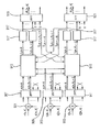
図5は、送信アンテナが2つある場合における、非特許文献7に開示されているチャネル推定方法を示す図である。この推定装置は複数の乗算器から構成されるが、同図では、第n番目の信号の第k番目の値r[n,k]に関連する3つ乗算器のみが示されている。第1乗算器901、第2乗算器903、第3乗算器905は、並列に配置され、ぞれぞれ第1の入力/出力および第2の入力/出力を備えている。第1乗算器901からの出力は第1逆高速フーリエ変換(IFFT)ブロック907に接続されており、第2乗算器903からの出力は第2逆高速フーリエ変換(IFFT)ブロック909に接続されており、第3乗算器905からの出力は第3逆高速フーリエ変換(IFFT)ブロック911に接続されている。計K個の乗算器が各IFFTブロックに接続されている。ここで、Kは周波数ドメインにおける受信信号の長さを表し、計3K個の入力信号が3つのIFFTブロックに供給される。IFFTブロック907、909、911は、それぞれK個の入力値に適用される逆フーリエ変換アルゴリズムを実行するように構成されている。さらに、IFFTブロック907、909、911の各々は、複数の出力を有するが、このうち各IFFTブロックにおける先頭からK0個の出力のみが使用される。残りの出力は、例えば、接地される。
FIG. 5 is a diagram illustrating a channel estimation method disclosed in Non-Patent Document 7 when there are two transmission antennas. This estimation apparatus is composed of a plurality of multipliers. In the figure, only three multipliers related to the kth value r [n, k] of the nth signal are shown. The
このIFFTブロック907からのK0個の出力は、第1推定ヴロック913に接続され、第3IFFTブロック911のK0個の出力は第2推定ブロック915に接続される。IFFTブロック909のK0個の出力は、第1推定ブロック913および第2推定ブロック915に接続されている。第1推定ブロック913および第2推定ブロック915は、K0個の出力を有しており、各出力はそれぞれ対応するフィルタ917に接続されており、各フィルタは1つの出力を備えている。第1推定ブロック913に対応するフィルタ917からのK0個の出力は、第1フーリエ変換(FFT)ブロック917に接続される一方、第2推定ブロック915に対応するフィルタ917のK0個の出力は、第2フーリエ変換(FFT)ブロック921に接続される。第1FFTブロック919および第2FFTブロック921は、K個の出力を備えている。ここで、上述したように、Kはサブキャリアの数である。更に、非特許文献7に開示されている単純化されたアルゴリズムに従って処理を行なうために、第1推定ブロック913に対応する第1のフィルタ917が第2推定ブロック915に接続され、第2推定ブロック913に対応する第2のフィルタ917はさらに第1推定ブロック913に接続されることにより、複数のフィードバックループが形成される。
K 0 outputs from the IFFT block 907 are connected to the
既に述べたように、図5は、送信アンテナが2つ存在するため、受信信号r[n,k]がチャネル雑音の影響を受ける2つの送信信号の重ね合わせになっている場合における、従来技術の予測装置の例を示している。受信信号は、図5に図示されぬ分割手段によって2つに分割される。続いて、対応する送信アンテナの複素共役信号を受信信号に乗算する。さらに、第1の送信アンテナから送信されたパイロットシンボルを第2の送信アンテナから送信されたパイロットシンボルに乗じる。より正確には、受信信号の第1のコピーのK個の値に、第1のアンテナから送信されたパイロットシンボル複素共役のK個の値を乗じる。受信信号の第2コピーのK個の値に対し、第2の送信アンテナから送信されたパイロットシンボルの複素共役のK個の値を乗じる。さらに、第1のアンテナから送信されたパイロットシンボルのK個の値に、第2の送信アンテナから送信されたパイロットシンボルの複素共役のK個の値を乗じることにより、チャネル推定アルゴリズムに必要な中間値を得る。 As described above, FIG. 5 shows the conventional technique in the case where the reception signal r [n, k] is a superposition of two transmission signals affected by channel noise because there are two transmission antennas. An example of the prediction device is shown. The received signal is divided into two by dividing means not shown in FIG. Subsequently, the reception signal is multiplied by the complex conjugate signal of the corresponding transmission antenna. Further, the pilot symbol transmitted from the first transmission antenna is multiplied by the pilot symbol transmitted from the second transmission antenna. More precisely, the K values of the first copy of the received signal are multiplied by K values of the pilot symbol complex conjugate transmitted from the first antenna. The K values of the second copy of the received signal are multiplied by K complex conjugate values of the pilot symbols transmitted from the second transmit antenna. Furthermore, by multiplying K values of pilot symbols transmitted from the first antenna by K values of complex conjugates of pilot symbols transmitted from the second transmitting antenna, intermediate values necessary for the channel estimation algorithm are obtained. Get the value.
上述したように、全ての乗算は並列に行なわれ、乗算器901により得られたK個の計算結果が第1のIFFTブロック907にフィードバックされる。K個の乗算器903の各々により得られたK個の計算結果は、第2のIFFTブロック909にフィードバックされる。K個の乗算器905の各々により得られたK個の計算結果は、第3IFFTブロック911にフィードバックされる。対応するそれぞれのIFFTブロックは、逆高速フーリエ変換を実行するように構成され、周波数ドメインの入力信号を時間ドメインの出力信号に変換する。
As described above, all multiplications are performed in parallel, and K calculation results obtained by the
第1推定ブロック913および第2推定ブロック915は、複数の入力信号に基づいてチャネル推定アルゴリズムを実行する機能を有する。より正確にいえば、第1推定ブロック913は3K0個の入力信号を受信し、第1送信アンテナから送信され該当する受信アンテナで受信された第1チャネルのチャネルインパルス応答に応じて、K0個の出力信号を生成する。同様に、第2推定ブロック915にて3K0個の入力信号が受信され、第2送信アンテナと当該受信アンテナとで構成される第2の通信チャネルに対応したK0個の出力信号が生成される。K0個の出力信号は、各々フィルタ917によりフィルタリングされる。
The
上述したように、チャネル推定ブロック913および915は、既に算出された値とIFFTブロックにて求められた値とに基づき、対応する通信チャネルのチャネルインパルス応答を推定するように構成されているので、フィルタからの出力信号は、各々第1推定ブロック913および第2推定ブロック915へフィードバックされる。各推定ブロックは、所望のチャネルインパルス応答を計算するために、逆行列ではなく行列ベクトル積を実行する推定アルゴリズムに従って動作する。フィルタリング処理と後段の高速フーリエ変換に必要な分のゼロパディング処理とを行なった後、第1通信チャネルおよび第2通信チャネルのチャネル伝達関数が得られる。
As described above, the channel estimation blocks 913 and 915 are configured to estimate the channel impulse response of the corresponding communication channel based on the values already calculated and the values obtained in the IFFT block. The output signals from the filters are fed back to the
上述したように、非特許文献7においては、行列ベクトル積が登場する反復法を導入し、パイロットシンボルの直交性を利用することにより、逆行列の計算を回避している。しかしながら、2つの通信チャネルに対応した2つのチャネルインパルス応答を計算するためには、3つの逆高速フーリエ変換と3K個の乗算処理を行なう必要がある。更に、非特許文献7のチャネル推定アルゴリズムは、行列ベクトル積を用いる結果、依然として計算が複雑である。よって、送信アンテナの数が増えると、複素数の乗算を行なう回数も増えるため、非特許文献7の推定方法は一層複雑さを増す。加えて、チャネル推定に必要な複数の中間値を得るためには、逆フーリエ変換を用いた2つのパイロットシンボルの乗算が必要となる。従って、推定ブロック913および915を独立に動作させることはできず、両推定ブロック間の処理タイミングを調整・制御する機構が新たに必要となる。
本発明は、簡易な構成でチャネル推定を効率よく行なう方法を提供することを目的とする。 An object of the present invention is to provide a method for efficiently performing channel estimation with a simple configuration.
上記目的は、請求項1に係るチャネル推定装置、請求項8に係るチャネル推定方法、または請求項9に係るコンピュータプログラムによって達成される。
The object is achieved by a channel estimation apparatus according to
本発明は、フーリエ変換の性質を効果的に利用することにより、フーリエ変換に基づくチャネル推定方法を単純化することが可能となるという知見に基づいてなされたものである。特に、異なるパイロット列(受信地点においてチャネル推定を行なうために必要な信号)を各送信地点から送信すれば、フーリエ変換に基づく変換(例えば、フーリエ変換や逆フーリエ変換)を実行することによって、複数の通信地点と1つの受信地点とに対応する通信チャネルの推定チャネルインパルス応答が得られる、ということを発見した。特に、パイロット列が互いに直交し位相にずれがある場合は、フーリエ変換に基づく変換によって、推定すべきチャネルの推定チャネル応答が直接的に導かれる。 The present invention has been made based on the knowledge that the channel estimation method based on the Fourier transform can be simplified by effectively utilizing the properties of the Fourier transform. In particular, if different pilot trains (signals necessary for channel estimation at the reception point) are transmitted from each transmission point, a plurality of pilot sequences (for example, Fourier transformation and inverse Fourier transformation) are performed by performing transformation based on Fourier transformation. It has been found that an estimated channel impulse response of the communication channel corresponding to the communication point and one receiving point can be obtained. In particular, when the pilot trains are orthogonal to each other and have a phase shift, the estimated channel response of the channel to be estimated is directly derived by the transform based on the Fourier transform.
例えば、少なくとも2つの送信地点からチャネル推定のためのパイロット列が送信される場合おいて、受信地点にて受信した信号にはそれぞれの送信地点から送信された信号の重ね合わせが含まれるが、この受信地点における受信信号は、単一のキャリア変調方法に従った時間ドメイン信号、またはマルチキャリア変調方法(例えばOFDM方式)に従った周波数ドメイン信号の両方が考えられる。 For example, when a pilot sequence for channel estimation is transmitted from at least two transmission points, a signal received at the reception point includes a superposition of signals transmitted from the respective transmission points. The reception signal at the reception point can be either a time domain signal according to a single carrier modulation method or a frequency domain signal according to a multicarrier modulation method (for example, OFDM scheme).
空間ダイバーシティ送信方式の利点を得る等の目的で、パイロット列は互いに異なっており、また各送信地点は空間的に離れている。従って、アンテナや受信地点などに設けられた受信信号をフィルタリングするためのフィルタ等を含んで構成される提供器により提供される入力信号には、対応する通信チャネルを用いて各送信地点から送信された信号の重ね合わせが含まれることになる。 In order to obtain the advantage of the spatial diversity transmission system, the pilot trains are different from each other, and the transmission points are spatially separated. Therefore, an input signal provided by a provider configured to include a filter for filtering a received signal provided at an antenna or a reception point is transmitted from each transmission point using a corresponding communication channel. Signal superposition.
2つの送信地点から情報が送信される上記の場合においては、入力信号には、一般的に異なる特性を持ち2つの物理チャネルにより送信された2つの信号の重ね合わせが含まれる。入力信号が、一般的に送信地点の数に等しいだけの複製(コピー)に分割されるような方法で多重化される場合は、当該入力信号の各コピーには対応するパイロット列情報が含まれる。ここで、パイロット列情報とは、そのパイロット列を送信したチャネルに対応付けられたチャネル情報に応じて導入される位相シフトのことである。 In the above case where information is transmitted from two transmission points, the input signal typically includes a superposition of two signals having different characteristics and transmitted over two physical channels. If the input signal is multiplexed in such a way that it is generally divided into duplicates equal to the number of transmission points, each copy of the input signal contains corresponding pilot sequence information. . Here, the pilot train information is a phase shift introduced according to channel information associated with the channel that transmitted the pilot train.
続いて、入力信号の各コピーは、推定すべきチャネルに対応するトレーニング信号から抽出された信号と乗算される。所定のパイロット列の位相情報を効果的に利用するフーリエ変換に基づき変換器によって入力信号の各コピーが変換される場合は、当該入力信号のコピーに適用される変換器によって得られた信号は、第1のチャネルのチャネルインパルス応答を含み、当該入力信号の他のコピーに適用される変換器により得られた信号は、他の通信チャネルのインパルス応答を含む。 Subsequently, each copy of the input signal is multiplied with the signal extracted from the training signal corresponding to the channel to be estimated. If each copy of the input signal is transformed by a converter based on a Fourier transform that effectively utilizes the phase information of a given pilot train, the signal obtained by the converter applied to the copy of the input signal is The signal obtained by the converter including the channel impulse response of the first channel and applied to another copy of the input signal includes the impulse response of the other communication channel.
非特許文献7に開示されている推定装置においては、チャネル推定方法にて要求される中間値を算出するために複数のフーリエ変換を実行する必要がある。これに対し本発明においては、受信機の構造を単純化し簡易なチャネル推定方法を実現するチャネルインパルス応答を推定するために必要なのは、1通信チャネル当たり1回のIDFT計算のみである。更に、従来の受信機の構造に対して改良が施された本発明に係る受信機構造に起因して、チャネル推定の性能に悪影響が出ることはない。 In the estimation device disclosed in Non-Patent Document 7, it is necessary to execute a plurality of Fourier transforms in order to calculate an intermediate value required in the channel estimation method. On the other hand, in the present invention, only one IDFT calculation is required per communication channel in order to estimate a channel impulse response that simplifies the receiver structure and realizes a simple channel estimation method. Further, the channel estimation performance is not adversely affected by the receiver structure according to the present invention, which is an improvement over the conventional receiver structure.
さらに、本発明のチャネル推定方法においては、中間値を取得するためにパイロット列の乗算を実行する必要がないため、乗算回数は著しく減少し、これにより推定方法が更にシンプルになる。 Furthermore, in the channel estimation method of the present invention, it is not necessary to perform pilot sequence multiplication to obtain an intermediate value, so the number of multiplications is significantly reduced, thereby further simplifying the estimation method.
加えて、本発明のチャネル推定方法においては、変換後の信号には推定すべきチャネルインパルス応答の推定値が含まれているから、従来技術のチャネル推定方法に比べて単純になる。従って、逆行列や行列ベクトル積は不要であり、これにより受信器の構造をさらに簡易なものにすることが可能となる。 In addition, in the channel estimation method of the present invention, the converted signal includes an estimated value of the channel impulse response to be estimated, which is simpler than the channel estimation method of the prior art. Therefore, an inverse matrix and a matrix vector product are not necessary, and this makes it possible to further simplify the structure of the receiver.
さらに、本発明のチャネル推定方法においては、推定すべきチャネルにて送信されたパイロット列の位相シフトに対し、所定のチャネル推定を実行する変換器を効率的に適応させることができるので、その位相シフトが受信地点において既知であるならば、互いに異なる位相シフトをもった直交するいかなる信号に対しても本発明の推定方法を適用することが可能である。さらに、本発明の方法は、周波数分割多重アクセスシステムや時間分割多重アクセスシステム等のあらゆる送信システムにおけるチャネル推定にも適用可能である。 Furthermore, in the channel estimation method of the present invention, the converter that performs the predetermined channel estimation can be efficiently adapted to the phase shift of the pilot train transmitted in the channel to be estimated. If the shift is known at the reception point, the estimation method of the present invention can be applied to any orthogonal signals with different phase shifts. Furthermore, the method of the present invention is applicable to channel estimation in any transmission system such as a frequency division multiple access system or a time division multiple access system.
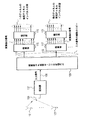
以下、図面を参照して、本発明の実施形態について詳説する。図1に、本発明に係るチャネル推定装置のブロック図を示す。この装置は、複数の送信アンテナによって特徴付けられる環境に適用される。図1においては、説明の便宜上、2つの送信アンテナ101および103のみが示されている。
Hereinafter, embodiments of the present invention will be described in detail with reference to the drawings. FIG. 1 shows a block diagram of a channel estimation apparatus according to the present invention. This device applies to environments characterized by multiple transmit antennas. In FIG. 1, only two
図1に示す装置は、提供部107に接続された出力を有する受信アンテナ105を備えている。提供部107は、入力信号の複製(コピー)を複数個提供する乗算器109に接続された出力を有する。乗算器109は複数の出力を有しており、その数は提供されるコピーの数(換言すれば送信地点の数)に対応している。説明の便宜上、乗算器109については、出力111および出力113のみを図1に示す。
The apparatus shown in FIG. 1 includes a receiving
出力111は変換器115に接続され、出力113は変換器117に接続される。変換器115および117は、それぞれ対応する変換器により実行される変換に応じた(より正確に言えば変換長に対応した)複数の出力を有する。
Output 111 is connected to
変換器115からの複数の出力は抽出器119に接続され、変換器117からの複数の出力は抽出器121に接続される。抽出器119および抽出器121は複数の出力を有する。抽出器119および121の出力の数は、それぞれ対応する変換器115および117の出力数に等しいか、もしくはそれよりも小さいことが好ましい。
A plurality of outputs from the
受信アンテナ105は、複数の送信地点からのアナログ信号を受信する。すなわち、入力信号には複数の送信地点からの信号の重ね合わせが含まれることになる。提供器107は、提供器107からの出力信号108が、使用されている復調方法に従った離散的な時間ドメイン信号または周波数ドメイン信号となるように、フィルタリング処理、アナログ/デジタル変換、復調等の処理を行う。例えば、OFCM変調方式が用いられる場合、入力信号は周波数ドメイン信号として出力される。単一キャリア変調方式が用いられる場合は、入力信号は時間ドメイン信号として出力される。
The
乗算器109は、出力108からの入力信号を受信し、当該入力信号のコピーを提供する。ここで、上述したように、コピーの数は送信地点の数に等しい。乗算器109は、例えば、入力信号の正確なコピーを複数個生成し、各々入力信号のコピーの1つと関連付けられた、送信地点の数に対応した複数の経路を生成する機能を有していてもよい。
入力信号のコピーの各々に対し、コピーまたは当該コピーから抽出された信号を変換するための変換器を設けるのが好ましい。図1においては、出力111で提供されるコピーは変換器115のみが受けとり、出力113にて提供されるコピー(他のコピー)は変換器115のみが受けとる。換言すれば、変換器115は出力111にて提供される入力信号のコピーのみを担当し、変換器117は出力113にて提供される入力信号のコピー(他のコピー)のみを担当する。さらに、図1に示すように、変換器115および117は互いに独立に動作する。
For each copy of the input signal, a converter is preferably provided for converting the copy or the signal extracted from the copy. In FIG. 1, only the
変換器115は、複数の出力を介して、1つの送信地点と受信地点の間の通信経路に対応した変換後の信号を提供する。変換器117は、複数の出力を介して、他の1つの送信地点と当該受信地点の間の他の通信経路に対応した変換後の信号を提供する。変換器115は、入力信号のコピー、もしくは例えば前置乗算処理によって当該コピーから抽出した信号に対し、フーリエ変換に基づいた変換アルゴリズムを適用する。変換器117は、フーリエ変換に基づいた変換アルゴリズムを、入力信号の他のコピーもしくは例えば前置乗算処理によって当該他のコピーから抽出した信号に対して適用する。
The
変換器115および変換器117は、例えば、フーリエ変換、離散フーリエ変換、高速フーリエ変換、逆フーリエ変換、または離散逆フーリエ変換を実行する機能を有していてもよい。一般的には、乗算器より提供された信号を変換するために設けられる複数の変換器は、所定のトレーニング信号の位相シフトを変換する変換アルゴリズムを実行して所定のチャネル情報を抽出する機能を有する。この処理は、具体的には、フーリエ変換に基づいたアルゴリズムに固有の性質を利用し、位相シフトを時間遅延に変換することにより実現することができる。
The
本発明のチャネル推定方法においては、入力信号の各コピーに対応した各処理経路における処理は、独立して実行される。処理経路の数は、送信地点の数または推定すべき通信チャネルの数に対応している。 In the channel estimation method of the present invention, processing in each processing path corresponding to each copy of the input signal is executed independently. The number of processing paths corresponds to the number of transmission points or the number of communication channels to be estimated.
更に、本発明のチャネル推定方法においては、変換器は推定すべき通信チャネルあたり1個のみ設ければ足りる。具体的には、NT個の送信地点からNT個の通信チャネルを推定するためのパイロット列が送信されるとすると、チャネル推定を行うために必要な変換器は最大でもNT個である。本発明のチャネル推定方法においては、各変換器を独立に動作させることができるので、いかなる中間値も用いることなくチャネル推定を行うことが可能となる。具体的には、特定の通信チャネルを推定するために必要なのは、1つの変換器と、それに対応した推定対象のチャネル(チャネルインパルス応答)に関連したパイロット列の情報の2つだけである。本発明の推定方法は、変換器間でのクロス接続やトレーニング信号の組み合わせから求めた中間演算結果を必要としない点で、従来のチャネル推定方法と相違する。 Furthermore, in the channel estimation method of the present invention, it is sufficient to provide only one converter for each communication channel to be estimated. Specifically, when the pilot sequence for estimating the N T communication channels from the N T transmitting points are transmitted, transducer necessary for performing channel estimation is the N T at most . In the channel estimation method of the present invention, each converter can be operated independently, so that channel estimation can be performed without using any intermediate value. Specifically, in order to estimate a specific communication channel, only two pieces of information of a pilot train related to one converter and a corresponding channel to be estimated (channel impulse response) are required. The estimation method of the present invention is different from the conventional channel estimation method in that an intermediate calculation result obtained from a cross connection between converters or a combination of training signals is not required.
本発明のチャネル推定方法においては、送信信号の各々に対し、当該送信信号の一部を抽出する抽出器を適用し、推定対象チャネルの推定チャネルインパルス応答を取得する。図1に示すように、抽出器119は変換器115から出力された変換後の信号の一部を抽出する一方、抽出器121は変換器117から出力された変換後の信号の一部を抽出する。このように、対応する変換後の信号の一部を抽出することにより、それぞれ変換器115および117により提供される離散化された値の一部のみが後段の装置にて使用される。
In the channel estimation method of the present invention, an extractor that extracts a part of the transmission signal is applied to each transmission signal, and an estimated channel impulse response of the estimation target channel is acquired. As shown in FIG. 1, the
例えば、抽出器119および121は、変換器115および117から出力される対応する変換後の信号から、複数の連続する値を抽出する機能を有していてもよい。ここで、当該連続する値の個数は、チャネルの既知の情報(チャネル長など)を用いて決定することができる。この場合、抽出器119ににて抽出された変換後の信号の長さは、推定対象チャネルのチャネル長よりも小さい。しかしながら、チャネルに関する既知の情報がチャネルのエネルギーである場合もあり得る。この場合、抽出器119は、抽出された変換後の信号の一部が例えばチャネルエネルギーの80%以上を有するように、抽出処理を行なう。変換後の信号のうち抽出されなかった離散値については、その値を例えばゼロにリセットするなどの処理を行なうことによって、破棄してもよい。抽出器121も抽出器119と同様の処理を行なう。
For example, the
更に、抽出器119および121は、対応する変換後の信号から、所定の閾値以上の値を抽出する機能を有していてもよい。ここで所定の閾値とは、例えば、抽出すべき値の絶対値が最小となる値を規定する値である。あるいは、所定の閾値を、変換後の信号に含まれる値の絶対値が最大となる値から求めてもよい。例えば、所定の閾値は、絶対値が最大となる値に0.2を乗じた値とすることができる。更に、変換後の信号の一部を抽出する際にエネルギーの基準を採用する場合は、変換後の信号に含まれる当該閾値を越える離散値が例えばチャネルエネルギーの80%以上を有するように、上記所定の閾値を選択してもよい。あるいは、破棄された(すなわち抽出されなかった)信号のエネルギーが例えばチャネルエネルギーの20%以下となるように、当該閾値を選択してもよい。閾値判定処理を実行するために、抽出器は、変換後の信号に含まれる離散化を閾値と比較するための比較器をさらに備えて構成されてもよい。
Furthermore, the
図1に示すように、抽出器119により抽出された変換後の信号の一部は、例えば送信地点101と受信アンテナ105の間のチャネルの推定チャネルインパルスである。抽出器121により提供された変換後の信号の一部は、例えば送信地点103と受信アンテナ105の間のチャネルの推定チャネルインパルスである。このように、各抽出器は対応する変換後の信号のみを受けとる。より具体的には、特に、チャネル推定に用いるパイロット列が所定の直交領域において互いに直行し且つその位相が互いにシフトしている場合に、フーリエ変換の性質を効果的に用いるため、各抽出器は、対応する変換器にて提供された変換後の信号のみに対し処理を行うことにより、対応するチャネルインパルス応答を独立に推定する。しかしながら、完全な直交性を実現するのは困難であるため、任意の2つのパイロット列の内積の絶対値がゼロ以上0.2以下であることが好ましい。この場合、上記所定の直交領域はゼロである第1の値と0.2である第2の値との間に属する領域として定義される。
As shown in FIG. 1, a part of the converted signal extracted by the
本発明の他の実施形態によれば、乗算処理および変換処理を相互に交換することが可能である。この場合、変換器は、フーリエ変換に基づく変換アルゴリズムを用いて入力信号または入力信号のコピーを変換し、変換後の信号が得られる。以下、好ましくはコピーの数は送信地点の数に等しい数の複数の変換後の信号のコピーが、乗算器から出力されるものとする。変換後のコピーの各々に対し、当該変換後の信号のコピーの一部を抽出するために抽出器が用いられ、推定対象チャネルの推定チャネルインパルス応答を取得する。 According to another embodiment of the present invention, multiplication processing and conversion processing can be exchanged with each other. In this case, the converter converts an input signal or a copy of the input signal using a conversion algorithm based on Fourier transform, and a converted signal is obtained. In the following, it is assumed that a plurality of copies of the converted signal, preferably having the number of copies equal to the number of transmission points, are output from the multiplier. For each transformed copy, an extractor is used to extract a portion of the transformed signal copy to obtain an estimated channel impulse response of the estimation target channel.
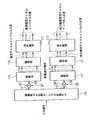
図2は、本発明の他の実施形態に係るチャネル推定装置を示す。再び、2つの送信地点(すなわち2つの通信チャネル)がある場合を考えることとする。 FIG. 2 shows a channel estimation apparatus according to another embodiment of the present invention. Again, consider the case where there are two transmission points (ie, two communication channels).
図1に示した装置と比較すると、図2に示す装置は、乗算器109の出力111に接続される入力と、変換器115に接続される出力203とを有する前置乗算器201を有している点で相違する。前置乗算器201は、入力202をさらに備えている。図2に示す装置は、更に、乗算器109の出力113に接続される入力と、変換器117に接続される出力209とを有する前置乗算器207を有している。前置乗算器207は、さらに入力208を備えている。
Compared to the device shown in FIG. 1, the device shown in FIG. 2 has a
さらに図1に示した装置と異なる点は、図2に示す装置は、抽出器119に接続される演算手段211を備えている点である。演算手段211は複数の出力を備えており、この出力の数は抽出器119の出力数以下となっている。加えて、図2に示す装置は、抽出器121に接続される演算手段213を備えている。演算手段213は、複数の出力を備えており、出力の数は抽出器121の出力数以下となっている。演算手段211は1つの通信経路に対応付けられており、演算手段213は、他の1つの通信経路と対応付けられている。
1 is different from the apparatus shown in FIG. 1 in that the apparatus shown in FIG. 2 includes a
前置乗算器201および207は、乗算器109と対応する変換器115との間に設けられる。乗算器109の出力111に対応する処理経路によって、1つの通信チャネルの推定に用いられる信号が提供され、乗算器109の出力113に対応する経路によって、他の1の通信チャネルの推定に用いられる信号が提供されることになる。
特に、前置乗算器201は、入力信号(すなわち出力111から提供された信号のコピー)に、推定対象チャネルを規定する送信地点に対応したパイロット列の複素共役を乗算する機能を有していてもよい。このパイロット列の複素共役は、入力202経由で前置乗算器201へ提供される。しかしながら、パイロット列が全て「1」の連続である場合、若しくはパイロット列の係数が小さな範囲である場合(すなわち、パイロット列の最大値と最小値の差の値の10%以内の範囲で変動する場合)、前置乗算器201は、出力111から提供された入力信号に対し何も処理を行なわず、そのまま変換器115へ提供する。
In particular, the pre-multiplier 201 has a function of multiplying an input signal (that is, a copy of a signal provided from the output 111) by a complex conjugate of a pilot sequence corresponding to a transmission point that defines an estimation target channel. Also good. This complex conjugate of the pilot train is provided to the
しかしながら、複数の異なるパイロット列が送信されるので、少なくとも1つののパイロット列は、「1」以外の係数を持つ。よって、前置乗算器207は、出力113から提供された入力信号(または入力信号の他のコピー)に、他の推定対象チャネルを規定する送信地点に対応付けられたパイロット列の複素共役を乗算することになる。
However, since a plurality of different pilot sequences are transmitted, at least one pilot sequence has a coefficient other than “1”. Thus, the pre-multiplier 207 multiplies the input signal (or another copy of the input signal) provided from the
ところで、対応する前置乗算器201および207に提供されるパイロット列は、必ずしも複素共役でなくてもよい。対応する前置乗算器201または207における乗算処理によって、共役が打ち消される場合があり得るからである。さらに、対応するパイロット列の複素共役をとるかわりに、例えば前置乗算器109と前置乗算器201または207と各々との間に新たに共役生成手段を設けることにより、各乗算器へ提供される入力信号のコピーの共役を生成してもよい。さらに、この前置乗算は、対応する変換器もしくは乗算器109によって実行されてもよい。
By the way, the pilot sequences provided to the corresponding premultipliers 201 and 207 do not necessarily have to be complex conjugates. This is because the conjugate may be canceled by the multiplication processing in the
さらに、例えば、入力信号がM-ary QAM(Mは4以上)を用いたOFDM変調方式に従ったものである場合、前置乗算器201および207は、乗算器109の出力から提供された入力信号(またはそのコピー)に、推定対象のチャネルに対応したパイロット列の逆数を乗じる。ここで、「パイロット列の逆数」とは、対応する逆数であってもよいしその複素共役であってもよい。この場合、本発明の装置は、上述の必要な逆数を計算する演算手段をさらに備えて構成されてもよい。あるいは、前置乗算器を必要な除算を実行するように構成してもよい。
Further, for example, when the input signal conforms to an OFDM modulation scheme using M-ary QAM (M is 4 or more), the
前置乗算器201により乗算された信号は変換器115に提供され、前置乗算器207により乗算された信号は変換器117に提供される。抽出器119および121にて上述した対応する変換後信号からチャネル推定値を抽出することができるように、変換器115および117は、対応する乗算済み信号に対して単一のアルゴリズムを適用する。
The signal multiplied by the
図2に示す装置は、演算手段211および213を有している点で図1に示した装置と相違する。演算手段211は、抽出器119によって提供された推定チャネルインパルス応答に基づき、拡張推定チャネルインパルス応答を提供する機能を有する。演算手段213は、抽出器121によって提供された推定チャネルインパルス応答に基づき、拡張推定チャネルインパルス応答を提供する機能を有する。例えば、演算手段211および213は、対応する推定チャネルインパルス応答に含まれる、チャネルのノイズ等に起因した推定誤差を減少させる機能を有する。
The apparatus shown in FIG. 2 is different from the apparatus shown in FIG. 1 in that it has calculation means 211 and 213. The
演算手段211および213で表される演算手段は、対応する抽出器119および121によって抽出された部分に対し、他のパイロット列に関する情報を用いずに、演算処理を行なう。演算手段211は、対応する処理経路に対応付けられた情報のみに基づき動作してもよい。すなわち、演算手段211は、他の処理経路に対応するパイロット列に関するいかなる情報も必要としない。同様に、演算手段213は、当該他のパイロット列に関する情報のみに基づき動作する。
The arithmetic means represented by the
これら演算手段は、各々チャネル推定手段を更に有していてもよい。例えば、最小平均2乗誤差(MMSE)法を用いた推定手段、最小2乗(LS)法を用いた推定手段、最尤度(ML)法に基づく推定手段、あるいはこれらの変形である。各演算手段は、精度の高い(拡張された)推定値を提供することにより、受信したチャネル推定に悪影響を及ぼすチャネルノイズを減少させる機能を有していてもよい。上記演算手段において、MMSE法に従ってフィルタ係数を決定するウィーナー(Wiener)フィルタリング等のフィルタ処理を実行してもよい。 Each of these calculation means may further include a channel estimation means. For example, estimation means using a minimum mean square error (MMSE) method, estimation means using a least square (LS) method, estimation means based on a maximum likelihood (ML) method, or a modification thereof. Each computing means may have a function of reducing channel noise that adversely affects the received channel estimation by providing a highly accurate (extended) estimated value. In the arithmetic means, a filter process such as Wiener filtering for determining a filter coefficient according to the MMSE method may be executed.
更に、上記演算手段は、対応するチャネル入力応答の推定に対して閾値判定を行う単純な閾値動作を実行し、対応するチャネル推定の係数が当該閾値以下の値を破棄するかまたは強制的にゼロにリセットしてもよい。この閾値は、例えば、上述したように、エネルギーを基準としてもよい。さらに、この閾値判定動作は、対応する抽出器から提供された各チャネル推定の係数であって、対応するチャネル推定長を小さい順に並べたときに後方にある係数に対してのみ適用してもよい。 Further, the arithmetic means executes a simple threshold operation for performing threshold judgment on the estimation of the corresponding channel input response, discards a value of the corresponding channel estimation coefficient equal to or less than the threshold, or forces zero. You may reset to This threshold value may be based on energy as described above, for example. Further, this threshold value determination operation may be applied only to the coefficient of each channel estimation provided from the corresponding extractor, which is behind when the corresponding channel estimation lengths are arranged in ascending order. .
更に、演算手段211および213は、上述した推定フィルタを備えていてもよい。拡張推定インパルス応答を繰り返し出力する際に対応する抽出器から抽出された部分に基づき、繰り返しこの推定フィルタを調整してもよい。例えば、上記演算手段は、現時点における拡張チャネル推定を提供するために、過去に取得した拡張チャネル推定に基づいてフィルタ係数を繰り返し決定する機能を有していてもよい。さらに、上記演算手段は、パイロット列が特定の時刻にのみ利用可能な場合や、1つの送信地点から送信された複数の連続したパイロット列が非常に小さくて十分にチャネル推定を行なうことができない場合に、チャネル追跡を行なう機能を有していてもよい。 Furthermore, the calculation means 211 and 213 may include the above-described estimation filter. The estimation filter may be adjusted repeatedly based on the portion extracted from the corresponding extractor when the extended estimated impulse response is repeatedly output. For example, the calculation means may have a function of repeatedly determining the filter coefficient based on the extended channel estimation acquired in the past in order to provide the extended channel estimation at the present time. Further, the above calculation means is used when the pilot train is available only at a specific time or when a plurality of continuous pilot trains transmitted from one transmission point are very small and channel estimation cannot be performed sufficiently. In addition, a channel tracking function may be provided.
パイロットシンボル利用型のチャネル推定を正確に記述するために、以下、周波数領域におけるサンプリンレートが^i=[[i/Df]]となるDf回サンプリングされたパイロット[^Y^l,^i (μ)]= [Yl,i (μ)]のみが含まれた受信信号の一部と、時間領域でサンプリングレートが^l=[[l/Dt]]となるDt回サンプリングされたパイロット[^Y^l,^i (μ)]= [Yl,i (μ)]のみが含まれた受信信号の一部とをそれぞれ定義する。ここで、[i,l]∈Gであり、"[["および“]]”は切り捨て記号(床関数記号)を表す。 In order to accurately describe pilot symbol-based channel estimation, D f times sampled pilots with ^ i = [[i / D f ]] in the frequency domain [^ Y ^ l, ^ Part of the received signal containing only i ( μ ) ] = [ Yl, i ( μ ) ] and Dt times sampling with sampling rate ^ l = [[l / Dt ]] in the time domain And a part of the received signal containing only the pilot [^ Y ^ l, ^ i ( μ ) ] = [ Yl, i ( μ ) ]. Here, [i, l] εG, and “[[” and “]]” represent a truncation symbol (floor function symbol).
サイズN'Pの列ベクトルで表すことができる、送信アンテナμから送信されるOFDMシンボルl=^lDtのパイロット列は、次式で表される。 A pilot sequence of OFDM symbol l = ^ lD t transmitted from transmission antenna μ, which can be expressed by a column vector of size N ′ P , is expressed by the following equation.
ここで、送信されたパイロット列、チャネル伝達関数(CTS)、およびノイズを表す項は、それぞれ次式によって与えられる。 Here, the transmitted pilot train, channel transfer function (CTS), and noise terms are given by the following equations, respectively.
N'P×N'PのサイズのDFT行列^Fを用いると、CIRは次式に従って周波数ドメインに変換される。 When a DFT matrix ^ F having a size of N ′ P × N ′ P is used, the CIR is converted into the frequency domain according to the following equation.
Q<N'Pの場合、最後からN'P-Q個のDFT出力を除去する必要があるが、これは、以下に示す主対角成分が「1」で残りは「0」となるN'P×Q次元の行列によって形式的に実行することができる。 'For P, N of the last' Q <N it is necessary to remove the P -Q number of DFT output, which is the remainder with leading diagonal are "1" below the "0" N 'It can be done formally with a P × Q dimensional matrix.
Q=N'Pの場合、行列I{N'P×N'P}は単位行列となる。実際には、DFT変換はN'P点のFFTを用いて効率的に生成することができる。Q<N'Pの場合は、最後からN'P-Q個の出力は省略される。以上により、次式が成り立つ。 'For P, the matrix I {N' Q = N P × N 'P} is the unit matrix. In practice, the DFT transform can be efficiently generated using an N ′ P- point FFT. 'For P, from the end N' Q <N P -Q number of output is omitted. From the above, the following equation is established.
時間ドメインのチャネル推定に関しては、送信されたパイロット列^X'^lに予め^Y'^lを乗じ、その結果をN'P点によるIDFT等を用いて時間ドメインに変換する。この処理を数学的に表すと以下のようになる。 For the channel estimation of the time domain, by multiplying the 'pre ^ Y to ^ l' ^ l transmitted pilot sequence ^ X, to convert the result to the time domain using IDFT due N 'P points. This process is expressed mathematically as follows.
ここで、^D'^l=^X'^l^FNTと定義する。この値と1/N'P^FH NTの積は、^FNT の各ブロックにつきN'P 点によるIDFTを1回実行することを意味している。 Here we define ^ D ' ^ l = ^ X' ^ l ^ F NT . The product of this value and 1 / N ′ P ^ F H NT means that IDFT with N ′ P points is executed once for each block of ^ F NT .
時間ドメインでのチャネル推定は、ξ^lを重み行列wによってフィルタリングする。これを数式で表すと以下のようになる。 Channel estimation in the time domain filters ξ ^ l with a weight matrix w. This is expressed by the following formula.
数式10においてハット記号を用いて表された左辺の量は、上述した^h' ^lと同じ構造をもつ。 The amount of the left side expressed using the hat symbol in Equation 10 has the same structure as ^ h ' ^ l described above.
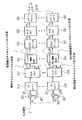
図3に、本発明の更に他の実施形態に係るチャネル推定装置を示す。同図で用いられる記号は上述した定義に従うものとする。 FIG. 3 shows a channel estimation apparatus according to still another embodiment of the present invention. The symbols used in the figure conform to the above definition.
図3において、受信地点で行なわれる各チャネルの推定に用いられるパイロット列が、複数の送信地点から送信される場合を考える。説明の便宜上、図3においては、NT個の送信地点(従ってNT個の通信チャネル)に対応した全部でNT個の経路のうち、2つの経路のみを示す。 In FIG. 3, a case is considered in which pilot sequences used for channel estimation performed at a reception point are transmitted from a plurality of transmission points. For convenience of explanation, in FIG. 3, among the N T path in total corresponding to the N T transmitting points (hence the N T communication channels), only two paths.
入力信号は、図3に示せぬ乗算器から提供される。この乗算器は、複数の出力を有しており、連続したNP個の出力は各前置乗算器に接続されている。図3に示す態様においては、1つの通信経路に対応する最初のNP個の出力は前置乗算器301に接続される一方、他の通信経路に対応した最後のNP個の出力は、前置乗算器303に接続される。前置乗算器301は、入力305および出力307を更に有している。同様に前置乗算器303は、入力309および出力311を更に有している。
The input signal is provided from a multiplier not shown in FIG. The multiplier has a plurality of output, N P number of output successive is connected to each front置乗adder. In the aspect shown in FIG. 3, the first N P outputs corresponding to one communication path are connected to the pre-multiplier 301, while the last N P outputs corresponding to the other communication paths are Connected to the pre-multiplier 303. The
更に、図3に示す装置は、NT個の周波数ドメイン(FD)ウィンドウを備えている。周波数ドメインウィンドウ313は前置乗算器301の出力307に接続される一方、周波数ドメインウィンドウ315は前置乗算器303の出力311に接続される。各周波数ドメインウィンドウは出力を備えている。周波数ドメインウィンドウ313からの出力は変換器317に接続される一方、周波数ドメインウィンドウ315からの出力は変換器319に接続される。変換器317および319は、NP点の逆フーリエ変換(IFFT)を実行する機能を有している。
In addition, the apparatus shown in FIG. 3 includes NT frequency domain (FD) windows. The
本実施形態においては、図2示したように複数の出力を抽出する抽出器を用いるのではなく、変換器317からの出力のうち最初からQ個目までの連続した出力をフィルタ321へ接続し、残りの出力を破棄する。同様に、変換器319からの出力のうち最初からQ個目までの連続した出力をフィルタ323へ接続し、残りの出力を破棄する。すなわち、各抽出器を、対応するQ個の出力に関するフィルタ321および323への機械的な接続に置き換えたのである。
In the present embodiment, instead of using an extractor that extracts a plurality of outputs as shown in FIG. 2, continuous outputs from the first to the Qth output from the
ゼロパディング器325は、NC点によるフーリエ変換を実行する機能を有するFFT変換器329に接続されたNC個の出力を備えている。同様に、ゼロパディング器327は、NC点によるフーリエ変換を実行する機能を有するFFT変換器331に接続されたNC個の出力を備えている。
Zero-
FFT変換器329は、複数の出力を備えたインバースウィンドウ333に接続されたNC個の出力を備えている。FFT変換器331のNC個の出力は、複数の出力を備えたインバースウィンドウ335に接続される。
The
図3に示すように、入力信号の各コピーは、対応する前置乗算器に提供される。入力信号の1つのコピーは、当該コピーに、推定対象チャネルを規定する送信ポイントに対応したトレーニング信号から導出可能な信号を乗じる前置乗算器301に提供される。 As shown in FIG. 3, each copy of the input signal is provided to a corresponding premultiplier. One copy of the input signal is provided to a pre-multiplier 301 that multiplies the copy by a signal that can be derived from the training signal corresponding to the transmission point that defines the channel to be estimated.
同様に、入力信号の他のコピーは、当該入力信号(NP個の離散値から構成される)の当該他のコピーに、他の推定対象チャネルを規定する送信ポイントに対応したトレーニング信号を乗じる機能を有する前置乗算器303に提供される。 Similarly, the other copy of the input signal multiplies the other copy of the input signal (consisting of N P discrete values) by a training signal corresponding to a transmission point that defines another estimation target channel. A pre-multiplier 303 having a function is provided.
ここで、パイロット列は、上述したように、自身の複素共役であってもよい。前置乗算器301および309にて乗算処理が施された信号は、対応する周波数ドメインウィンドウ313および315へ提供される。各周波数ドメインウィンドウにおいては、後段のIFFT処理に起因するリーケージ効果(leakage effect)を緩和することを目的として、周波数窓処理が実行される。例えば、周波数ドメインウィンドウ313および315は、対応する乗算済み信号に対しフィルタ処理を施し、リーケージ効果が小さくなるように変換すべき信号を加工する。
Here, as described above, the pilot train may be its own complex conjugate. The signals multiplied by the
続いて、IFFT変換器317および319は、それぞれ独立に、周波数ドメインウィンドウ313および315から提供された出力信号に対して提供されるIFFTアルゴリズムを実行する。
Subsequently,
上述したように、フィルタ321および323は、例えばそれぞれのチャネル推定で生じるチャネル推定誤差を減らす等により、それぞれ、推定チャネルインパルス応答から拡張チャネルインパルス応答を提供し、他の推定チャネルインパルス応答から他の拡張推定チャネルインパルス応答を提供するための、フィルタ処理を実行する機能を有してもよい。フィルタ321および323は、例えば、MMSE法、LS法、またはML法を用いた推定を実行する。フィルタ321および323は、上述した閾値判定処理を実行する機能をさらに有していてもよい。
As described above, filters 321 and 323 each provide an extended channel impulse response from the estimated channel impulse response and reduce other channel estimation responses from other estimated channel impulse responses, for example, by reducing channel estimation errors that occur in each channel estimation. It may have the function of performing filtering to provide an extended estimated channel impulse response. The
IFFT変換器317および319からの出力信号を、直接、時間ドメイン信号または周波数ドメイン信号の等化処理に適用することも可能である。 図3に示す装置は、一例として、単一キャリア送信システムにおけるチャネル推定に適用される。時間ドメインにおいては、例えば、分散フィードバック等化器を用いて等化を行なうことができる。更に、チャネル推定および拡張チャネル推定の結果には、チャネルの符号化/復号化に使用可能なチャネル状態情報が含まれている。
It is also possible to directly apply the output signals from the
対応する推定インパルス応答、または対応する拡張推定インパルス応答に対応したチャネル伝達関数を取得するため、フィルタ321から提供された拡張推定インパルス応答に後段の高速フーリエ変換を適用し、ある1の高速フーリエ変換をフィルタ323から提供された他の拡張推定インパルス応答に適用する。両変換器において、拡張推定チャネルインパルスに対応するチャネル伝達関数と、他の拡張推定チャネルインパルスに対応するチャネル伝達関数とを取得するために、所定の拡張チャネル推定が周波数ドメインに変換される。
In order to obtain a corresponding estimated impulse response or a channel transfer function corresponding to the corresponding extended estimated impulse response, a subsequent fast Fourier transform is applied to the extended estimated impulse response provided from the
対応するFFTを実行するに先立ち、対応する後段のFFT変換器329および331にて実行すべきFFTに必要な長さの分だけ、各拡張チャネル推定に対しゼロパディング処理が施される。より具体的には、ゼロパディング器325は、当該ゼロパディング器325からの出力信号が後段のFFT変換において必要な長さであるNCに等しくなるように、フィルタ323により提供された拡張推定チャネルインパルス応答を拡張する。同様に、ゼロパディング器327からFFT変換器331にNC個の離散値が提供されるように、フィルタ323にて提供された拡張推定チャネルインパルス応答を拡張する。
Prior to executing the corresponding FFT, zero padding processing is performed on each extension channel estimation by the length necessary for the FFT to be executed by the corresponding
周波数ドメインウィンドウ313および315における処理に起因した影響を緩和するために、FFT変換を行なった後、インバースウィンドウ333および335にて逆窓処理を実行する。
In order to mitigate the influence caused by the processing in the
フィルタ321、ゼロパディング器325、FFT変換器329、およびインバースウィンドウ333は、1つの処理経路に対応した演算手段を構成する一方、フィルタ323、ゼロパディング器327、FFT変換器331、およびインバースウィンドウ335は、他の処理経路に対応した演算手段を構成する。
The
上述したように、各々1つの送信アンテナから送信された信号に対応するNT個のパイロット列を受信したパイロット列に乗じた後、IDFTを用いて時間ドメインへの変換を行なう。DFTに基づく補間は、単純に、推定チャネルインパルス応答にNc-Q個のゼロを付加することにより行なう。このゼロパディングにより、複数のサンプルの長さ^h'^l(この「^」はチルダ記号ではなくハット記号を表す)をサンプル数の数まで拡張する。これは次式で表される。 As described above, after NT pilot sequences corresponding to signals transmitted from one transmission antenna are multiplied by the received pilot sequences, conversion to the time domain is performed using IDFT. DFT-based interpolation is simply done by adding N c -Q zeros to the estimated channel impulse response. This zero padding extends the length of multiple samples ^ h ' ^ l (where "^" represents a hat symbol, not a tilde symbol) to the number of samples. This is expressed by the following equation.
ここで、h'^lDt (μ)はベクトルを表す。フィルタ処理によって、チャネル推定は時間ドメインにおいて改善される。図3をみれば分かるように、NC点のDFT処理によって、パイロット列の推定チャネルインパルス応答は、全体のOFDMシンボルの周波数応答推定へ変換される。 Here, h ′ ^ lDt ( μ ) represents a vector. Filtering improves channel estimation in the time domain. As can be seen from FIG. 3, the estimated channel impulse response of the pilot train is converted into a frequency response estimate of the entire OFDM symbol by the N C point DFT processing.
チャネルインパルス応答が有限時間に終わると仮定すると、ξ^lは完全に時間有限となり、FFTに基づく補間は単純なゼロパディングにより実行される。なお、1つの送信アンテナ当たりの出力数がNT分の1に減少するため、パイロット間隔Dfが1である場合であってもゼロパディング処理は必要である。 Assuming that the channel impulse response ends in a finite time, ξ ^ l is completely time finite and the FFT based interpolation is performed with simple zero padding. Since the number of outputs per transmission antenna is reduced to 1 / NT , even when the pilot interval D f is 1, zero padding processing is necessary.
全OFDMシンボル(パイロットおよびデータ)のチャネル伝達関数の推定値は、ゼロパディングされたチャネルインパルスの推定値に対しNC点のFFTを行なうことにより求められる。これは次式で表される。 The estimated value of the channel transfer function of all OFDM symbols (pilot and data) is obtained by performing N C point FFT on the estimated value of the zero-padded channel impulse. This is expressed by the following equation.
ここで、FNtは、NC点のDFT行列F内のNT 個のブロックから構成された、サイズNTNC×NTNCのブロック対角化されたDFT行列を表す。 Here, F Nt represents a block diagonalized DFT matrix composed of N T blocks in the N C -point DFT matrix F and having a size N T N C × N T N C.
DFTを効率的に実行するには、高速フーリエ変換アルゴリズムを用いればよい。変換効率が最適となるのは、サンプリング点の数が2の階乗となる必要がある。 In order to execute DFT efficiently, a fast Fourier transform algorithm may be used. The conversion efficiency is optimal because the number of sampling points needs to be a factorial of two.
しかしながら、実際のシステムにおいては、NCおよびN'Pが常に2の階乗であるとは限らない。よって、高速フーリエ変換を実行するために、ゼロパディングが用いられることになる。出力において、取得したチャネル伝達関数の最後から幾つかのサンプリング点に対しては、所望の推定精度を確保するために、処理を行わない。 However, in an actual system, N C and N ′ P are not always the factorial of 2. Thus, zero padding is used to perform the fast Fourier transform. In the output, processing is not performed on several sampling points from the end of the acquired channel transfer function in order to ensure a desired estimation accuracy.
このようにすることで、時間ドメインにおける変換も同様に調整される。補間比は1/ Dfでなければならないからである。この補間比は、周波数Dfのパイロット間隔を定義するものであり、時間ドメインへの逆DFTと周波数ドメイン1/ Dfへの再変換との比の逆数に等しい。以下においては、最小2乗法を用いた推定を行なう。D'^l HD'^lの逆行列が存在するとして、最小2乗予測値は次式で与えられる。
By doing so, the transformation in the time domain is adjusted in the same way. Interpolation ratio is because should be 1 / D f. This interpolation ratio defines the pilot interval of frequency D f and is equal to the inverse of the ratio of inverse DFT to time domain and retransformation to
この予測値は送信信号に依存するので、パイロット列を適切に選択する必要がある。D'^lがフルランク(full rank)であればLS予測値は存在するが、残念ながら常にそうであるとは限らない。LS予測値が存在するための条件は、次式で与えられる。 Since this prediction value depends on the transmission signal, it is necessary to appropriately select the pilot train. If D ' ^ l is full rank, there is an LS prediction, but unfortunately it is not always the case. The condition for the existence of the LS predicted value is given by the following equation.
![]()
![]()
実際には、オーバサンプリングを2回行うのが、パイロット信号処理に起因したシステム負荷の最小化と実行結果の最適化とのトレードオフに関して理想的である。 In practice, performing oversampling twice is ideal in terms of a trade-off between minimizing system load due to pilot signal processing and optimizing execution results.
以下、ウィーナーフィルタについて説明する。ウィーナーフィルタは、受信したパイロットのMMSEを最小にする推定器である。従って、MMSE推定器とも呼ばれ、有限インパルス応答(FIR)フィルタとして記述される。一般的には、ウィーナーフィルタは、所望のシンボルの位置nに依存する。MMSEによる推定値を算出するためには、相関行列R'ξξおよびR'hξが必要となる。OFDMシンボルのMMSE推定値は次式で与えられる。 Hereinafter, the Wiener filter will be described. The Wiener filter is an estimator that minimizes the MMSE of the received pilot. Therefore, it is also called an MMSE estimator and is described as a finite impulse response (FIR) filter. In general, the Wiener filter depends on the position n of the desired symbol. In order to calculate an estimated value by MMSE, correlation matrices R ′ ξξ and R ′ hξ are required. The MMSE estimate for the OFDM symbol is given by:
ここで、相関行列R'ξξおよびR'hξは次式にて定義される。 Here, the correlation matrix R'ξξ and R 'h xi] is defined by the following equation.
時間ドメインにおける共分散R'^h^hは、周波数ドメインにおける共分散行列R'^H^Hとの間に次式で示す関係を有している。 The covariance R ′ ^ h ^ h in the time domain has a relationship represented by the following equation with the covariance matrix R ′ ^ H ^ H in the frequency domain.
各送信アンテナからの信号には互いに相関がないと仮定すると、R'^h^h=E[^h'^l^h'^l H]で定義される自己相関行列は、次式で示すようなブロック対角化された形を有する。 Assuming that the signals from each transmitting antenna are not correlated with each other, the autocorrelation matrix defined by R ' ^ h ^ h = E [^ h' ^ l ^ h ' ^ l H ] is given by The block has a diagonalized shape.
さらに、次式の関係がある。
ここで「0」は、適切な次元の全ての零行列を表す。上述の方程式は、サンプル間隔(sample spaced)のチャネルのみに対して厳密に成立する。 Here, “0” represents all zero matrices of appropriate dimensions. The above equation is strictly valid for only sample spaced channels.
LS予測法においては、D'^lがフルランクであることが要求されるのに対し、MMSE予測法においては、上述の通りR'ξξの正則性が要求されるが、D'^lがフルランクである必要はない。よって、MMSE予測法は、N'P< NTQの場合も適用可能である。D'^lがフルランクの場合は、D'^l HD'^lの逆行列が存在する。よって、ウィーナーフィルタは、次式のような形に単純化できる。 In LS estimation method, 'whereas ^ l is required to be full rank, in the MMSE estimation method, as R above' D but regularity of ξξ is required, D '^ l is It doesn't have to be full rank. Therefore, the MMSE prediction method can also be applied when N ′ P <N T Q. If D ' ^ l is full rank, there is an inverse matrix of D' ^ l H D ' ^ l . Therefore, the Wiener filter can be simplified into the following equation.
すると、MMSE予測値は以下で与えられる
上式は、LS予測値が、MMSE予測法の入力として機能していることを意味している。上記第2式においてD'^l HD'^lをその平均値に置き換えることにより、MMSE予測値は、D'^lから得られる送信パイロットとは独立に算出することができる。LS予測法に従って実行されるNT個の信号を分離する処理は、フィルタ処理と分離することが可能となることが分かる。 The above equation means that the LS prediction value functions as an input for the MMSE prediction method. By replacing D ′ ^ l H D ′ ^ l with the average value in the second equation, the MMSE prediction value can be calculated independently of the transmission pilot obtained from D ′ ^ l . It can be seen that the process of separating NT signals performed according to the LS prediction method can be separated from the filter process.
一般的には、チャネルタップ間には、複数の送信アンテナのフェージングと同様、互いに相関がない。従って、サンプル間隔チャネルについては、自己相関行列は以下に示すような対角化された形になる。 In general, there is no correlation between channel taps as in the fading of a plurality of transmission antennas. Therefore, for the sample interval channel, the autocorrelation matrix has a diagonalized form as shown below.
ここで、[σ(1) Q]2は第1送信アンテナのチャネルタップQの受信信号強度の平均値を表している。 Here, [σ (1) Q ] 2 represents the average value of the received signal strength of the channel tap Q of the first transmitting antenna.
以下、最適なパイロット列を生成する方法について説明する。MMSE予測器は、一般的にはパイロットシンボルの選択に依存する。しかしながら、適切なパイロット列を選択すれば、MMSE推定器は送信されたパイロットに依存しない。MMSE(すなわち推定器の推定精度)および計算量が最小となるような1組のパイロット列を選ぶことが好ましい。推定器の主な計算上の負荷は、LS法やMMSE法を用いた従来のチャネル推定方法において必要となるD'^l HD'^lの逆行列の計算に起因するものである。D'^l HD'^lが対角化されている場合は、次式に示すように、計算負荷の高い逆行列の計算を避けることができる。 Hereinafter, a method for generating an optimal pilot train will be described. MMSE predictors generally rely on the selection of pilot symbols. However, if an appropriate pilot train is selected, the MMSE estimator does not depend on the transmitted pilot. It is preferable to choose a set of pilot sequences that minimizes MMSE (ie, the estimation accuracy of the estimator) and complexity. The main computational load of the estimator is due to the calculation of the inverse matrix of D ′ ^ l H D ′ ^ l required in the conventional channel estimation method using the LS method or the MMSE method. When D ′ ^ l H D ′ ^ l is diagonalized, calculation of an inverse matrix having a high calculation load can be avoided as shown in the following equation.
以下、D'^l HD'^lを対角化して上記数式が成り立つための十分条件を導く。 In the following, D ′ ^ l H D ′ ^ l is diagonalized to derive sufficient conditions for the above formula to hold.
受信機の構造が複雑になるのを最小限に抑えるためには、D'^l HD'^lを対角化するのが好ましい。こうすれば、LS法およびMMSE法に基づく推定を大幅に単純化することができる。対角化のための必要条件は、NP≧NTQである。行列D'^l HD'^lは以下のように表すことができる。 In order to minimize the complexity of the receiver structure, it is preferable to diagonalize D ′ ^ l H D ′ ^ l . In this way, estimation based on the LS method and the MMSE method can be greatly simplified. The prerequisite for diagonalization is N P ≧ N T Q. The matrix D ′ ^ l H D ′ ^ l can be expressed as:
なお、^FH^X' ^l (μ)H^X' ^l (m) ^Fのブロックは、Q×Q次元である。 Note that the block of ^ F H ^ X ' ^ l ( μ ) H ^ X' ^ l (m) ^ F has a Q × Q dimension.
対角行列であるために必要な条件は、次の通りである。 The conditions necessary to be a diagonal matrix are as follows.
上記第1式は、任意のパイロット列に対して成り立つ。それは、以下に示す関係があるからである。 The first equation holds for an arbitrary pilot train. This is because of the relationship shown below.
以下、数26式を満たす十分条件を導く。この際、ベクトルξ^l,nの成分で考えるのが便利である。一般性を損なわずに、アンテナ1からの信号を推定することを考える。すると、要素ξ^l,n (1)は以下の形に書くことができる。
Hereinafter, sufficient conditions that satisfy Equation 26 are derived. At this time, it is convenient to consider the components of the vector ξ ^ l, n . Consider estimating the signal from the
上式の各項は、さらに以下のように変形することができる。 Each term of the above formula can be further modified as follows.
ここで、^n^l,nは、平均白色ガウス型雑音(AWGN)プロセスを表し、IDFTを行なう前に、^n^l,^iに^X(1) ^l,^iを乗じることによって生成される。最内の項は、基本的には^X(1)* ^l,^i^X(μ) ^l,^iの逆フーリエ変換である。 Here, ^ n ^ l, n has an average represents a white Gaussian noise (AWGN) process, before performing IDFT, ^ n ^ l, ^ i to ^ X (1) ^ l, multiplying the ^ i Generated by. The innermost term is basically the inverse Fourier transform of ^ X (1) * ^ l, ^ i ^ X ( μ ) ^ l, ^ i .
送信パイロット列のフーリエ変換の性質を詳細に調べる前に、任意の数列に対するDFTを以下のように定義する。 Before examining in detail the nature of the Fourier transform of the transmitted pilot sequence, the DFT for any number sequence is defined as follows:
更に、以下の数列を定義する。 Further, the following number sequence is defined.
ここで、δkは単位インパルス関数を表し、その定義は次式で与えられる。 Here, [delta] k represents a unit impulse function, its definition is given by the following equation.
ここでkは、1≦k<NTを満たす任意の定数である。従って、次式が導かれる。 Here, k is an arbitrary constant that satisfies 1 ≦ k <N T. Therefore, the following equation is derived.
よって、ξ^l,n (1)の直交性に対する十分条件は、次式を満たすような一組のパイロット列を選択することであることが分かる。 Thus, it can be seen that a sufficient condition for the orthogonality of ξ ^ l, n (1) is to select a set of pilot sequences that satisfy the following equation.
すると、次式のような単純な形が得られる。 Then, a simple form like the following formula is obtained.
この条件は、D'^l HD'^lを対角化するための条件と同じである。アダマール(Hadamard)数列等の直交数列に対するDFTの性質を調べれば、数式34が満たされていることを示すことができる。さらに、後述するように、次式で表される位相シフトした数列もまた数式を34満たす。 This condition is the same as the condition for diagonalizing D ′ ^ l H D ′ ^ l . Examining the DFT properties for orthogonal sequences such as Hadamard sequences can show that Equation 34 is satisfied. Further, as will be described later, the phase-shifted number sequence represented by the following equation also satisfies the equation 34.
これら位相シフトした数列を用いて、さらに受信機の構造を単純化することも可能である。^X(1)* ^l,^i (μ) ^X(μ) ^l,^i (μ)のDFTは次式で与えられる。 It is possible to further simplify the structure of the receiver by using these phase-shifted sequences. ^ X (1) * ^ l, ^ i ( μ ) ^ X ( μ ) ^ l, ^ i ( μ ) DFT is given by the following equation.
![]()
![]()
この結果を用いると、ξ^l,n (1)は以下のように求まる。 Using this result, ξ ^ l, n (1) is obtained as follows.
以上により、パイロット列が適切に選択されれば、MMSE推定器およびLS推定器を大幅に単純化することができる。 As described above, if the pilot train is appropriately selected, the MMSE estimator and the LS estimator can be greatly simplified.
予測器は、選択したパイロット列に依存しないから、フィルタの生成が非常に簡単になることが分かる。 Since the predictor does not depend on the selected pilot train, it can be seen that the filter generation is very simple.
サンプル間隔チャネルの場合は、ウィーナーフィルタは以下のような特別な形になる。 For the sample interval channel, the Wiener filter takes the special form:
サンプル間隔チャネルでない場合、ウィーナーフィルタの最適解は対角行列ではない。しかし、多くの場合、次最適なタップ数1のフィルタを選択することができる。 Without the sample interval channel, the optimal solution of the Wiener filter is not a diagonal matrix. However, in many cases, it is possible to select a filter with the next optimal number of taps of one.
更に、本発明のチャネル推定方法は、要求に応じて、ハードウェアまたはソフトウェアのどちらにでも実装することが可能である。本発明の方法を実装するにあたっては、本発明の方法を実行することができるように、プログラム可能なコンピュータシステムと協働する電磁的に読出し可能な制御信号が格納されるディスクまたはCD等のデジタル方式の記録媒体を用いてもよい。従って、本発明は、コンピュータ読み取り可能な媒体に格納された、プログラムコードを備えたコンピュータプログラム製品として実現され得る。このプログラムコードは、コンピュータプログラムがコンピュータ上で実行されたときに本発明の方法を実行するものである。換言すれば、本発明の方法は、コンピュータ上で実行されたときに、本発明の方法を実行するプログラムコードを有するコンピュータプログラムとして実現され得る。 Furthermore, the channel estimation method of the present invention can be implemented in either hardware or software as required. In implementing the method of the present invention, a digital disc such as a disk or CD on which electromagnetically readable control signals cooperating with a programmable computer system are stored so that the method of the present invention can be implemented. A recording medium of a system may be used. Thus, the present invention can be implemented as a computer program product with program code stored on a computer readable medium. This program code is for executing the method of the present invention when the computer program is executed on the computer. In other words, the method of the present invention can be realized as a computer program having program code for executing the method of the present invention when executed on a computer.
Claims (9)
前記複数の送信地点から送信された複数の信号の重ね合わせを含む入力信号を提供する提供器(107)と、
前記複数の送信地点の数に等しい数だけ前記入力信号の複製を提供する乗算器(109)と、
前記入力信号の複製の位相シフトを時間遅延に変換するためにフーリエ変換に基づく変換アルゴリズムを適用する機能を有し、前記入力信号の複製の各々に対し、前記複製または当該複製から得られる信号を変換して変換後の信号を得る変換器(115、117;317、319)と、
対応する変換器(115、117;317、319)のみから提供された変換後の信号のみを受信する機能を有し、前記変換後の信号の各々に対し、前記変換後の信号からその一部分を抽出し、推定対象のチャネルの推定チャネルインパルス応答を取得する抽出器(119、121)と
を有し、
前記乗算器(109)と前記変換器(115、117;317、319)との間に、前記複製から抽出された信号を生成するための前置乗算器(201、207;301、303)が接続され、
前記前置乗算器は、前記変換器から出力された信号を用いて推定されるべきチャネルを規定している送信地点に対応したパイロット列の複素共役を、入力信号に乗じる
ことを特徴とするチャネル推定装置。There are two or more transmission points that are spatially separated, and each of the two or more transmission points is associated with a corresponding one pilot sequence of a plurality of pilot sequences, and the plurality of pilot sequences are arbitrary two An apparatus for estimating a channel from one transmission point to one reception point in an environment where the absolute values of the inner products of the pilot trains are orthogonal to each other within an orthogonality range defined by 0 or more and 0.2 or less ,
A provider (107) for providing an input signal including a superposition of a plurality of signals transmitted from the plurality of transmission points;
A multiplier (109) providing a copy of the input signal by a number equal to the number of the plurality of transmission points;
A function of applying a transform algorithm based on Fourier transform to convert a phase shift of the replica of the input signal into a time delay, and for each replica of the input signal, the replica or a signal obtained from the replica Converters (115, 117; 317, 319) for converting and obtaining converted signals;
A function of receiving only the converted signals provided only from the corresponding converters (115, 117; 317, 319), and for each of the converted signals, a part of the converted signal is obtained. extracted, organic and extractor to obtain an estimated channel impulse response estimation target channel (119, 121),
Between the multiplier (109) and the converter (115, 117; 317, 319), a pre-multiplier (201, 207; 301, 303) for generating a signal extracted from the replica is provided. Connected,
The pre-multiplier multiplies the input signal by a complex conjugate of a pilot sequence corresponding to a transmission point that defines a channel to be estimated using the signal output from the converter.
A channel estimation apparatus.
前記抽出器(119、121)の各々について、対応する抽出器(119、121)にて抽出された前記一部に対し、他のパイロット列に関する情報を用いずに、演算処理を実行する演算手段(211、213)を更に有する
ことを特徴とする請求項1に記載のチャネル推定装置。The pilot column is phase shifted to the doctor each other,
For each of the extractors (119, 121), arithmetic means for performing arithmetic processing on the part extracted by the corresponding extractor (119, 121) without using information on other pilot strings The channel estimation apparatus according to claim 1, further comprising (211, 213).
前記フィルタ係数は、同一の前記抽出器(119、121)から抽出された部分に基づき複数の時刻において繰り返し変更される
ことを特徴とする請求項2に記載のチャネル推定装置。The arithmetic means (211 and 213) includes estimation filters (321 and 323) having predetermined filter coefficients, and has a function of outputting the estimated channel impulse response,
The channel estimation apparatus according to claim 2, wherein the filter coefficient is repeatedly changed at a plurality of times based on portions extracted from the same extractor (119, 121).
ことを特徴とする請求項2または3に記載のチャネル推定装置。The arithmetic means (211 and 213) includes a zero padding unit (325 and 327) that performs a zero padding process on the estimated impulse response or the extended estimated channel impulse response to obtain a predetermined length. The channel estimation apparatus according to claim 2 or 3.
ことを特徴とする請求項4に記載のチャネル推定装置。The calculation means (211 and 213) convert the zero-padded estimated channel impulse response or the zero-padded extended estimated channel impulse response and output a channel transfer function of the estimation target channel (329 and 331). The channel estimation apparatus according to claim 4, further comprising:
前記ゼロパディングされた、推定チャネルインパルス応答または拡張推定チャネルインパルス応答に対し、窓処理を行い、前記チャネル伝達関数における前記周波数ドメインウィンドウ(313、315)に起因した影響を緩和させるインバースウィンドウ(333、335)と、
を更に備えることを特徴とする請求項4に記載のチャネル推定装置。A frequency domain window (313, 315) that performs windowing on each of the replicas or a signal obtained from each of the replicas in order to mitigate the leakage effect in the subsequent conversion;
An inverse window (333, 333) that performs windowing on the zero-padded estimated channel impulse response or extended estimated channel impulse response to mitigate the influence due to the frequency domain window (313, 315) in the channel transfer function. 335),
The channel estimation apparatus according to claim 4, further comprising:
ことを特徴とする請求項1ないし4のいずれかに記載のチャネル推定装置。The channel estimation according to any one of claims 1 to 4, wherein the extractor (119, 121) extracts a value from a signal having a value equal to or greater than a predetermined threshold among the converted signals. apparatus.
前記複数の送信地点から送信された複数の信号の重ね合わせを含む入力信号を提供するステップと、
前記複数の送信地点の数に等しい数だけ前記入力信号の複製を提供する乗算ステップと、
前記入力信号の複製の各々に対し、前記入力信号の複製の位相シフトを時間遅延に変換するためにフーリエ変換に基づく変換アルゴリズムを適用することにより、前記複製または当該複製から得られる信号を変換して変換後の信号を得る変換ステップと、
前記変換後の信号の各々に対し、対応する変換後の信号のみを受信し、前記変換後の信号からその一部分を抽出して推定対象のチャネルの推定チャネルインパルス応答を取得するステップと
を有するチャネル推定方法であって、
前記乗算ステップにて出力された信号に基づき、前記複製から抽出された信号を生成する前置乗算ステップとを更に有し、
前記前置乗算ステップにおいては、前記変換ステップから出力された信号を用いて推定されるチャネルを規定している送信地点に対応したパイロット列の複素共役を、入力信号に乗じる
ことを特徴とするチャネル推定方法。There are two or more transmission points that are spatially separated, and each of the two or more transmission points is associated with a corresponding one pilot sequence of a plurality of pilot sequences, and the plurality of pilot sequences are arbitrary two A method for estimating a channel from one transmission point to one reception point in an environment orthogonal to each other within an orthogonality range defined by an absolute value of an inner product of pilot sequences of 0 or more and 0.2 or less ,
Providing an input signal including a superposition of a plurality of signals transmitted from the plurality of transmission points;
A multiplication step for providing a copy of the input signal by a number equal to the number of the plurality of transmission points;
For each of the replicas of the input signal, transform the replica or a signal obtained from the replica by applying a transformation algorithm based on Fourier transform to convert the phase shift of the replica of the input signal into a time delay A conversion step for obtaining a converted signal by
Receiving only a corresponding converted signal for each of the converted signals, extracting a part of the converted signal, and obtaining an estimated channel impulse response of a channel to be estimated; An estimation method,
A pre-multiplication step for generating a signal extracted from the replica based on the signal output in the multiplication step;
In the pre-multiplication step, an input signal is multiplied by a complex conjugate of a pilot sequence corresponding to a transmission point that defines a channel estimated using the signal output from the conversion step. Estimation method.
ことを特徴とするコンピュータプログラム。A computer program comprising program code for executing the channel estimation method according to claim 8 when executed by a computer.
Applications Claiming Priority (1)
| Application Number | Priority Date | Filing Date | Title |
|---|---|---|---|
| PCT/EP2003/005376 WO2004114615A1 (en) | 2003-06-22 | 2003-06-22 | Apparatus and method for estimating a channel in a multiple input transmission system |
Publications (2)
| Publication Number | Publication Date |
|---|---|
| JP2006506024A JP2006506024A (en) | 2006-02-16 |
| JP4099191B2 true JP4099191B2 (en) | 2008-06-11 |
Family
ID=33522222
Family Applications (1)
| Application Number | Title | Priority Date | Filing Date |
|---|---|---|---|
| JP2005500860A Expired - Lifetime JP4099191B2 (en) | 2003-06-22 | 2003-06-22 | Channel estimation apparatus and channel estimation method |
Country Status (7)
| Country | Link |
|---|---|
| US (1) | US7529310B2 (en) |
| EP (1) | EP1512258B1 (en) |
| JP (1) | JP4099191B2 (en) |
| CN (1) | CN1643867B (en) |
| AU (1) | AU2003237658A1 (en) |
| DE (1) | DE60325049D1 (en) |
| WO (1) | WO2004114615A1 (en) |
Families Citing this family (63)
| Publication number | Priority date | Publication date | Assignee | Title |
|---|---|---|---|---|
| US9130810B2 (en) | 2000-09-13 | 2015-09-08 | Qualcomm Incorporated | OFDM communications methods and apparatus |
| US7295509B2 (en) | 2000-09-13 | 2007-11-13 | Qualcomm, Incorporated | Signaling method in an OFDM multiple access system |
| DE60301270T2 (en) * | 2003-03-27 | 2006-07-20 | Nnt Docomo, Inc. | DEVICE AND METHOD FOR ESTIMATING A MULTIPLE OF CHANNELS |
| JP4356392B2 (en) * | 2003-08-07 | 2009-11-04 | パナソニック株式会社 | Communication device |
| KR20050075242A (en) * | 2004-01-16 | 2005-07-20 | 삼성전자주식회사 | Pilot channel-based channel estimation method for mc-cdma system using frequency interleaving |
| JP2008501275A (en) * | 2004-05-28 | 2008-01-17 | コーニンクレッカ フィリップス エレクトロニクス エヌ ヴィ | Signal processing method and signal processor in OFDM system |
| US9137822B2 (en) | 2004-07-21 | 2015-09-15 | Qualcomm Incorporated | Efficient signaling over access channel |
| US9148256B2 (en) | 2004-07-21 | 2015-09-29 | Qualcomm Incorporated | Performance based rank prediction for MIMO design |
| US8040968B2 (en) * | 2004-09-30 | 2011-10-18 | Intel Corporation | High rate, high diversity transmission on multiple transmit antennas |
| US7649861B2 (en) * | 2004-11-30 | 2010-01-19 | Intel Corporation | Multiple antenna multicarrier communication system and method with reduced mobile-station processing |
| US7822128B2 (en) * | 2004-12-03 | 2010-10-26 | Intel Corporation | Multiple antenna multicarrier transmitter and method for adaptive beamforming with transmit-power normalization |
| WO2006091916A2 (en) * | 2005-02-23 | 2006-08-31 | Wionics Research | Ultrawideband architecture |
| CA2599739A1 (en) * | 2005-03-01 | 2006-09-08 | Qualcomm Incorporated | Channel estimate optimization for multiple transmit modes |
| US8135088B2 (en) * | 2005-03-07 | 2012-03-13 | Q1UALCOMM Incorporated | Pilot transmission and channel estimation for a communication system utilizing frequency division multiplexing |
| US9246560B2 (en) | 2005-03-10 | 2016-01-26 | Qualcomm Incorporated | Systems and methods for beamforming and rate control in a multi-input multi-output communication systems |
| US9154211B2 (en) | 2005-03-11 | 2015-10-06 | Qualcomm Incorporated | Systems and methods for beamforming feedback in multi antenna communication systems |
| US9520972B2 (en) | 2005-03-17 | 2016-12-13 | Qualcomm Incorporated | Pilot signal transmission for an orthogonal frequency division wireless communication system |
| US9461859B2 (en) * | 2005-03-17 | 2016-10-04 | Qualcomm Incorporated | Pilot signal transmission for an orthogonal frequency division wireless communication system |
| US9143305B2 (en) | 2005-03-17 | 2015-09-22 | Qualcomm Incorporated | Pilot signal transmission for an orthogonal frequency division wireless communication system |
| US9184870B2 (en) | 2005-04-01 | 2015-11-10 | Qualcomm Incorporated | Systems and methods for control channel signaling |
| US7848463B2 (en) * | 2005-04-07 | 2010-12-07 | Qualcomm Incorporated | Adaptive time-filtering for channel estimation in OFDM system |
| US9036538B2 (en) | 2005-04-19 | 2015-05-19 | Qualcomm Incorporated | Frequency hopping design for single carrier FDMA systems |
| US9408220B2 (en) | 2005-04-19 | 2016-08-02 | Qualcomm Incorporated | Channel quality reporting for adaptive sectorization |
| US8879511B2 (en) | 2005-10-27 | 2014-11-04 | Qualcomm Incorporated | Assignment acknowledgement for a wireless communication system |
| US8565194B2 (en) | 2005-10-27 | 2013-10-22 | Qualcomm Incorporated | Puncturing signaling channel for a wireless communication system |
| US9179319B2 (en) | 2005-06-16 | 2015-11-03 | Qualcomm Incorporated | Adaptive sectorization in cellular systems |
| EP1746756B1 (en) * | 2005-07-21 | 2013-01-16 | STMicroelectronics Srl | A method and system for decoding signals, corresponding receiver and computer program product |
| US20070064828A1 (en) * | 2005-07-22 | 2007-03-22 | Aldana Carlos H | Method and system for multiple input multiple output (MIMO) channel estimation |
| US8885628B2 (en) | 2005-08-08 | 2014-11-11 | Qualcomm Incorporated | Code division multiplexing in a single-carrier frequency division multiple access system |
| US9209956B2 (en) | 2005-08-22 | 2015-12-08 | Qualcomm Incorporated | Segment sensitive scheduling |
| US20070041457A1 (en) | 2005-08-22 | 2007-02-22 | Tamer Kadous | Method and apparatus for providing antenna diversity in a wireless communication system |
| JP5002215B2 (en) | 2005-08-24 | 2012-08-15 | パナソニック株式会社 | MIMO receiving apparatus and MIMO receiving method |
| US9136974B2 (en) | 2005-08-30 | 2015-09-15 | Qualcomm Incorporated | Precoding and SDMA support |
| JP4612511B2 (en) * | 2005-09-09 | 2011-01-12 | シャープ株式会社 | Receiving apparatus and receiving method |
| US9225416B2 (en) | 2005-10-27 | 2015-12-29 | Qualcomm Incorporated | Varied signaling channels for a reverse link in a wireless communication system |
| US9210651B2 (en) | 2005-10-27 | 2015-12-08 | Qualcomm Incorporated | Method and apparatus for bootstraping information in a communication system |
| US9144060B2 (en) | 2005-10-27 | 2015-09-22 | Qualcomm Incorporated | Resource allocation for shared signaling channels |
| US9172453B2 (en) | 2005-10-27 | 2015-10-27 | Qualcomm Incorporated | Method and apparatus for pre-coding frequency division duplexing system |
| US9225488B2 (en) | 2005-10-27 | 2015-12-29 | Qualcomm Incorporated | Shared signaling channel |
| US9088384B2 (en) | 2005-10-27 | 2015-07-21 | Qualcomm Incorporated | Pilot symbol transmission in wireless communication systems |
| US8045512B2 (en) | 2005-10-27 | 2011-10-25 | Qualcomm Incorporated | Scalable frequency band operation in wireless communication systems |
| US8265209B2 (en) * | 2005-10-28 | 2012-09-11 | Qualcomm Incorporated | Method and apparatus for channel and noise estimation |
| US7929597B2 (en) * | 2005-11-15 | 2011-04-19 | Qualcomm Incorporated | Equalizer for a receiver in a wireless communication system |
| US8831607B2 (en) | 2006-01-05 | 2014-09-09 | Qualcomm Incorporated | Reverse link other sector communication |
| US8130857B2 (en) * | 2006-01-20 | 2012-03-06 | Qualcomm Incorporated | Method and apparatus for pilot multiplexing in a wireless communication system |
| US8094709B2 (en) * | 2006-02-01 | 2012-01-10 | Nec Corporation | Equalizer and equalization method |
| KR101225649B1 (en) * | 2006-07-25 | 2013-01-23 | 뉴저지 인스티튜트 오브 테크놀로지 | Apparatus and method for channel estimation in multiple antenna communication system |
| JP4991870B2 (en) * | 2006-10-27 | 2012-08-01 | テレフオンアクチーボラゲット エル エム エリクソン(パブル) | Method and receiver for simplifying whitening calculation in G-RAKE receiver |
| US7684504B2 (en) * | 2006-10-31 | 2010-03-23 | Freescale Semiconductor, Inc. | System and method for reducing edge effect |
| JP4827723B2 (en) * | 2006-12-27 | 2011-11-30 | パナソニック株式会社 | OFDM receiver |
| US20080232237A1 (en) * | 2007-03-19 | 2008-09-25 | Legend Silicon Corp. | Method and apparatus for robust timing recovery of ofdm system for fast fading channels |
| US8046396B2 (en) * | 2007-03-28 | 2011-10-25 | Teradyne, Inc. | Residual Fourier-padding interpolation for instrumentation and measurement |
| KR101422014B1 (en) | 2007-05-10 | 2014-07-23 | 엘지전자 주식회사 | Method For Generating Long Code By Repeating Basic Code, And Method For Transmitting Control Information Using The Same |
| WO2009025376A1 (en) * | 2007-08-17 | 2009-02-26 | Nec Corporation | Method and apparatus for channel estimation in ofdm |
| US8509208B2 (en) | 2008-02-01 | 2013-08-13 | Qualcomm Incorporated | Frequency error estimation |
| JP4691119B2 (en) * | 2008-02-14 | 2011-06-01 | 日本電信電話株式会社 | Weight calculation device and weight calculation method |
| US8831063B2 (en) * | 2008-03-18 | 2014-09-09 | Qualcomm Incorporated | Single carrier burst structure for decision feedback equalization and tracking |
| US8611288B1 (en) * | 2009-03-05 | 2013-12-17 | Marvell International Ltd | Systems and methods for link adaptation in wireless communication systems |
| US8982803B1 (en) | 2009-03-05 | 2015-03-17 | Marvell International Ltd. | Systems and methods for link adaption in wireless communication systems |
| CN101951307B (en) * | 2010-09-24 | 2013-01-23 | 西安电子科技大学 | Method for selecting cell cooperation set under CoMP |
| CN103281265A (en) * | 2013-05-02 | 2013-09-04 | 电子科技大学 | Pilot sequence structure in MIMO-OFDM/OQAM (Multi-input Multi-output-Orthogonal Frequency Division Multiplexing/Offset Quadrature Amplitude Modulation) system and channel estimation method |
| WO2024036630A1 (en) * | 2022-08-19 | 2024-02-22 | Nvidia Corporation | Signal processing in parallel |
| CN115694767B (en) * | 2022-10-27 | 2023-07-14 | 南通大学 | Combined pilot frequency design, feedback and channel estimation method based on transducer |
Family Cites Families (5)
| Publication number | Priority date | Publication date | Assignee | Title |
|---|---|---|---|---|
| JP3737264B2 (en) * | 1998-01-14 | 2006-01-18 | 株式会社東芝 | Diversity receiver |
| US6317411B1 (en) * | 1999-02-22 | 2001-11-13 | Motorola, Inc. | Method and system for transmitting and receiving signals transmitted from an antenna array with transmit diversity techniques |
| US6850481B2 (en) * | 2000-09-01 | 2005-02-01 | Nortel Networks Limited | Channels estimation for multiple input—multiple output, orthogonal frequency division multiplexing (OFDM) system |
| JP4237708B2 (en) | 2003-02-14 | 2009-03-11 | 株式会社エヌ・ティ・ティ・ドコモ | Two-dimensional channel estimation for multi-carrier multiple I / O communication systems |
| US7221722B2 (en) * | 2003-02-27 | 2007-05-22 | Motorola, Inc. | Method and apparatus for reducing interference within a communication system |
-
2003
- 2003-06-22 CN CN03807345.5A patent/CN1643867B/en not_active Expired - Fee Related
- 2003-06-22 AU AU2003237658A patent/AU2003237658A1/en not_active Abandoned
- 2003-06-22 JP JP2005500860A patent/JP4099191B2/en not_active Expired - Lifetime
- 2003-06-22 DE DE60325049T patent/DE60325049D1/en not_active Expired - Lifetime
- 2003-06-22 EP EP03735438A patent/EP1512258B1/en not_active Expired - Fee Related
- 2003-06-22 WO PCT/EP2003/005376 patent/WO2004114615A1/en active Search and Examination
-
2004
- 2004-10-15 US US10/967,044 patent/US7529310B2/en active Active
Also Published As
| Publication number | Publication date |
|---|---|
| DE60325049D1 (en) | 2009-01-15 |
| AU2003237658A1 (en) | 2005-01-04 |
| CN1643867A (en) | 2005-07-20 |
| JP2006506024A (en) | 2006-02-16 |
| CN1643867B (en) | 2010-06-23 |
| US20050047518A1 (en) | 2005-03-03 |
| EP1512258B1 (en) | 2008-12-03 |
| EP1512258A1 (en) | 2005-03-09 |
| US7529310B2 (en) | 2009-05-05 |
| WO2004114615A1 (en) | 2004-12-29 |
Similar Documents
| Publication | Publication Date | Title |
|---|---|---|
| JP4099191B2 (en) | Channel estimation apparatus and channel estimation method | |
| US7327812B2 (en) | Apparatus and method for estimating a plurality of channels | |
| WO2007112489A1 (en) | Channel estimation for rapid dispersive fading channels | |
| CN109309542B (en) | Orthogonal signal division multiplexing underwater acoustic communication method based on time domain oversampling | |
| JP4388077B2 (en) | Apparatus and method for effective channel estimation and apparatus and method for providing a pilot sequence | |
| Qin et al. | Structured distributed compressive channel estimation over doubly selective channels | |
| Tseng et al. | Subspace-based blind channel estimation for OFDM by exploiting cyclic prefix | |
| JP4125722B2 (en) | Channel estimation using guard interval of multi-carrier signal | |
| KR100578723B1 (en) | Method and device for dft-based channel estimation in a mimo-ofdm system with pilot subcarriers | |
| EP1584168B1 (en) | Apparatus and method for processing an impulse response of a channel | |
| JP4483218B2 (en) | Space-time transmit diversity multi-carrier CDMA receiver, transmitter, and radio communication system including the receiver | |
| JP4463852B2 (en) | Apparatus and method for iteratively estimating channel transfer function | |
| JP2002330089A (en) | Method and device for gmmse-type equalizing, and receiver | |
| JP2002330114A (en) | Method and system for gmmse-type equalization and receiver | |
| Ribeiro et al. | An OFDM Symbol Design for Reduced Complexity MMSE Channel Estimation. | |
| Sun et al. | A subspace-based channel identification algorithm for forward link in space-time coded MC-CDMA systems | |
| JP6306857B2 (en) | Receiving apparatus and program | |
| KR100630380B1 (en) | Apparatus for providing multiple input and multiple output in digital multimedia broadcasting system and method of the same | |
| JP6491439B2 (en) | Receiving apparatus and program | |
| Patra et al. | A Low Complexity SFBC-OFDM Channel Estimation in Fast Fading Channel | |
| Chen et al. | Adaptive constrained CM-based multicarrier-CDMA receivers in multipath fading channels | |
| Lin | Channel estimation for wireless OFDM communications | |
| XI | Blind channel estimation for MIMO OFDM communication systems |
Legal Events
| Date | Code | Title | Description |
|---|---|---|---|
| A711 | Notification of change in applicant |
Free format text: JAPANESE INTERMEDIATE CODE: A711 Effective date: 20060622 |
|
| A521 | Request for written amendment filed |
Free format text: JAPANESE INTERMEDIATE CODE: A821 Effective date: 20060622 |
|
| A131 | Notification of reasons for refusal |
Free format text: JAPANESE INTERMEDIATE CODE: A131 Effective date: 20070320 |
|
| A521 | Request for written amendment filed |
Free format text: JAPANESE INTERMEDIATE CODE: A523 Effective date: 20070521 |
|
| TRDD | Decision of grant or rejection written | ||
| A01 | Written decision to grant a patent or to grant a registration (utility model) |
Free format text: JAPANESE INTERMEDIATE CODE: A01 Effective date: 20080311 |
|
| A61 | First payment of annual fees (during grant procedure) |
Free format text: JAPANESE INTERMEDIATE CODE: A61 Effective date: 20080314 |
|
| R150 | Certificate of patent or registration of utility model |
Ref document number: 4099191 Country of ref document: JP Free format text: JAPANESE INTERMEDIATE CODE: R150 Free format text: JAPANESE INTERMEDIATE CODE: R150 |
|
| FPAY | Renewal fee payment (event date is renewal date of database) |
Free format text: PAYMENT UNTIL: 20110321 Year of fee payment: 3 |
|
| FPAY | Renewal fee payment (event date is renewal date of database) |
Free format text: PAYMENT UNTIL: 20110321 Year of fee payment: 3 |
|
| FPAY | Renewal fee payment (event date is renewal date of database) |
Free format text: PAYMENT UNTIL: 20120321 Year of fee payment: 4 |
|
| R250 | Receipt of annual fees |
Free format text: JAPANESE INTERMEDIATE CODE: R250 |
|
| FPAY | Renewal fee payment (event date is renewal date of database) |
Free format text: PAYMENT UNTIL: 20120321 Year of fee payment: 4 |
|
| FPAY | Renewal fee payment (event date is renewal date of database) |
Free format text: PAYMENT UNTIL: 20130321 Year of fee payment: 5 |
|
| R250 | Receipt of annual fees |
Free format text: JAPANESE INTERMEDIATE CODE: R250 |
|
| FPAY | Renewal fee payment (event date is renewal date of database) |
Free format text: PAYMENT UNTIL: 20130321 Year of fee payment: 5 |
|
| FPAY | Renewal fee payment (event date is renewal date of database) |
Free format text: PAYMENT UNTIL: 20140321 Year of fee payment: 6 |
|
| R250 | Receipt of annual fees |
Free format text: JAPANESE INTERMEDIATE CODE: R250 |
|
| R250 | Receipt of annual fees |
Free format text: JAPANESE INTERMEDIATE CODE: R250 |
|
| R250 | Receipt of annual fees |
Free format text: JAPANESE INTERMEDIATE CODE: R250 |
|
| R250 | Receipt of annual fees |
Free format text: JAPANESE INTERMEDIATE CODE: R250 |
|
| R250 | Receipt of annual fees |
Free format text: JAPANESE INTERMEDIATE CODE: R250 |
|
| R250 | Receipt of annual fees |
Free format text: JAPANESE INTERMEDIATE CODE: R250 |
|
| R250 | Receipt of annual fees |
Free format text: JAPANESE INTERMEDIATE CODE: R250 |
|
| R250 | Receipt of annual fees |
Free format text: JAPANESE INTERMEDIATE CODE: R250 |
|
| R250 | Receipt of annual fees |
Free format text: JAPANESE INTERMEDIATE CODE: R250 |
|
| R250 | Receipt of annual fees |
Free format text: JAPANESE INTERMEDIATE CODE: R250 |
|
| R250 | Receipt of annual fees |
Free format text: JAPANESE INTERMEDIATE CODE: R250 |
|
| EXPY | Cancellation because of completion of term |