JP4098897B2 - Synthetic resin board panel and method for manufacturing the same - Google Patents
Synthetic resin board panel and method for manufacturing the same Download PDFInfo
- Publication number
- JP4098897B2 JP4098897B2 JP27176798A JP27176798A JP4098897B2 JP 4098897 B2 JP4098897 B2 JP 4098897B2 JP 27176798 A JP27176798 A JP 27176798A JP 27176798 A JP27176798 A JP 27176798A JP 4098897 B2 JP4098897 B2 JP 4098897B2
- Authority
- JP
- Japan
- Prior art keywords
- synthetic resin
- dimensional pattern
- panel
- flat
- joint
- Prior art date
- Legal status (The legal status is an assumption and is not a legal conclusion. Google has not performed a legal analysis and makes no representation as to the accuracy of the status listed.)
- Expired - Lifetime
Links
Images


Description
【0001】
【発明の属する技術分野】
この発明は、庭園の塀や垣根に用いられる、合成樹脂製の塀板用パネルおよびその製造方法に関する。
【0002】
【従来の技術】
従来、和風の庭園等には、天然竹の割竹を使い、これを複数本の柱と胴縁による枠組みに、縦に多数並列して取付け、前記胴縁と割竹と同材の押え縁との間に縦に多数並列状に挟み、棕縄等により固定した竹垣が、塀や垣根に古くから賞用されてきた。
【0003】
ところが、天然竹を使った塀や垣根は、雅趣なおもむきを与える反面、その製作には高度の熟練と手間を要しするだけでなく、太陽光、風雨、気温変化等の自然環境に晒されて、変色し、腐食して朽ち、耐久性に劣るというという欠点がある。そして、最近ではむしろコスト的にも高くつくものとなっている。
【0004】
近年、上記のような天然竹による欠点を解消するために、合成樹脂を用いて、天然竹の風合を外観的に取入れるべく形状と色彩を模し、割竹を多数連接し一体化した外観に仕上げ、塀や垣根としての作業を簡単にし、しかも耐久性に富むパネル体としたものが知られている。例えば、特許第2527146号公報(公知例1)には、天然竹の色彩を有する合成樹脂製の断面円弧状の細長い割竹形状の割竹部を幅方向に多数連接してパネル状本体を形成するとともに、前記パネル状本体の側端の一方または両方に該側端に沿って該パネル本体の厚み幅の凹溝部を設けかつ該凹溝部の外側には接続部を一体に張設した合成樹脂製竹パネルが開示されており、また特開昭63−161273号公報(公知例2)には、前記公知例1の合成樹脂製竹パネルと同様のパネルとともに、天然竹の色彩に着色せしめた合成樹脂製にて表裏両面対向状の細長い割竹形状に形成せしめた割竹部を短手方向に連続形成せしめたパネル体が開示されている。
【0005】
ところが、前記公知例1のパネルは、パネル同士を連結する際に、他のパネルの側端を前記凹溝部に収容載置するだけで連結できるから、パネル同士の連結が簡単容易にかつ確実に行えしかも継ぎ目がほとんど目立たず外観美麗であるという利点はあるものの、パネルはそれ自体が片面用に構成されているものであり、これを両面の塀や垣根として用いる場合には、柱間の胴縁に両側面から個々のパネルを棕縄や釘によって取付けを行わねばならず、塀や垣根の現場施工は決して簡単容易とはいえない。
【0006】
また、前記公知例2のパネルは、その両側端に互いに雌雄嵌合する凸部と凹溝を形成するかまたは対向する突片を設けて連結できるから、パネル同士の連結が簡単容易にかつ確実に行えしかも継ぎ目がほとんど目立たず外観美麗である点で前記公知例1と同様の利点を有し、しかもパネルの両面に割竹形状が形成されている点では前記公知例1に比べて現場施工がやや簡単になるといえる。しかしながら、まだ現場施工が簡単容易というには不十分であり、その上パネル自体は両面が断面円弧状に膨出した部分と谷状部分との連続形状を有するものであり、かつ中実体であるから、パネルの強度を確保する上で厚さを縮小するにも限度があり必然的に重量の大きいものとなり、材料コストも高いものとなるという欠点がある。
【0007】
【発明が解決しようとする課題】
この発明は、かかる従来の欠点を解決して、この種合成樹脂製の塀板用パネルの連結を簡単容易に行え、かつ確実にして強固に施工することができ、しかも顕著な立体感を呈し、外観品質に優れた構造の合成樹脂製塀板用パネルとその製造方法を提供することを目的とする。
【0008】
【課題を解決するための手段】
すなわち、この発明の第1の発明は、表裏両層に複数の割竹様凸条よりなる立体模様部を並列状に形成し外周端縁を接合した熱可塑性合成樹脂製の中空成形体であって、隣接する前記立体模様部を互いに一定幅の帯状平坦部を介して形成し、かつ表裏両層を左右方向に前記立体模様部の1列分を、上下方向に所定幅分を夫々合じゃくり状にずらし、ずらし出された各縁部の前記立体模様部の対応層には平坦な継手部を形成するとともに、前記各帯状平坦部の少なくとも1部において表裏両層を接合した補強部を形成することによって、中空成形体内の空間を実質的に連通状態としたことを特徴とする合成樹脂製塀板用パネルを要旨とする。
【0009】
また、この発明の第2の発明は、請求項1の合成樹脂製塀板用パネルを製造するための製造方法であって、割竹様の凸状の前記立体模様部と、隣接する該立体模様部間の前記帯状平坦部と、合じゃくり状にずらし出された各縁部の平坦継手部との各部分に対応するキャビティーを有し、前記各キャビティーの外周縁にはシート挟着部を、また前記各キャビティーの内面と前記シート挟着部には微細な多数の空気吸引孔と、さらに前記平坦継手部に対応するキャビティーの各平坦部には進退自在な少なくとも1個以上の加圧空気導入ノズルとが設置されており、さらにまた前記各帯状平坦部の少なくとも1部において表裏両層を接合するための隆起部が形成された左右一対の金型を用い、該金型間に熱可塑性合成樹脂を可塑化した円筒状のパリソンを両金型の面方向に偏平化させて垂下させ、両金型を閉じながら前記空気吸引孔から負圧吸引しつつ前記熱可塑性合成樹脂の表裏両層を前記シート挟着部で挟着して接合するとともに、両金型のキャビティーに吸着させながら、前記加圧空気導入ノズルを前記熱可塑性合成樹脂の両層間に侵入させて加圧空気を導入し、キャビティーの前記隆起部では前記熱可塑性合成樹脂の両層を接合する以外は、全空間を実質的に連通状態にして中空状としたのち、前記加圧空気導入ノズルを後退させて中空成形体を取出し、前記立体模様部の外周を切除することを特徴とする合成樹脂製塀板用パネルの製造方法を要旨とする。
【0010】
以下、この発明の第1の発明である合成樹脂製塀板用パネルと、第2の発明である前記合成樹脂製塀板用パネルの製造方法を図面にしたがって説明する。
【0011】
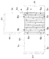
まず、第1の発明の合成樹脂製塀板用パネルは、図1および図2で示すとおり、合成樹脂製塀板用パネル(1)において、表層および裏層に複数の割竹様凸条よりなる立体模様部(2)を一定幅(w)の帯状平坦部(3)を介して並列状に形成し、外周端縁を接合することによって中空状とした熱可塑性合成樹脂製の中空成形体から構成する。そして、表裏両層を左右方向に前記立体模様部(2)の1列分を、また上下方向に所定幅分を夫々合じゃくり状にずらし、ずらし出された各縁部の前記立体模様部(2)の対応層(4a)(4b)を平坦状にして継手部(4)を形成し、さらに前記各帯状平坦部(3)の少なくとも1部において表裏両層を接合した補強部(3a)を形成することによって、中空成形体内の空間を実質的に連通状態とする。
【0012】
合成樹脂製塀板用パネル(1)は、外観的には前記の各立体模様部(2)が個々に独立空間を形成された中空成形体のごとくに見えるが、その内部構造は、図3(イ)〜(ハ)で示す各切断部の端面で明らかなように、各立体模様部(2)において、その表裏両面を接合した前記帯状平坦部(3)の補強部(3a)と、中空成形体の外周端縁を除く大部分は、図3(ハ)で示されるように、実質的に連通状態からなる構造からなっている。
【0013】
ここで、前記各立体模様部(2)の間に配置された前記帯状平坦部(3)は、該帯状平坦部(3)の存在によって前記各立体模様部(2)自体の立体間を視覚的に高める作用をし、また前記補強部(3a)は、図3(ロ)で示されるように、前記帯状平坦部(3)の一部で表裏両層を接合した構造としたから、当該パネル(1)全体の剛性を向上する役目を果たす。
【0014】
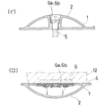
また、この発明の第1の発明の好ましい実施態様は、図4に示すように、合成樹脂製塀板用パネル(1)のずらし出された各縁部において、左右ないし上下方向に他の合成樹脂製塀板用パネル(1n)を連結するために、該パネル(1n)の継手部(4n)に対応する位置の立体模様部(2)の頂部に、ボルト挿入孔(5a)(5b)を設け、さらに継手部(4)において他の合成樹脂製塀板用パネル(1n)の各ボルト挿入孔(5n)に対応する位置に、板状ナット(6a)(6b)を、前記継手部(4)と面一となるように埋め込んだ状態に装着した構造の合成樹脂製塀板用パネル(1)とする。
【0015】
この場合、合成樹脂製塀板用パネル(1)の前記ボルト挿入孔(5a)(5b)、および板状ナット(6a)(6b)は、いずれも表層に設けられており、裏層には設けられていない。従って、裏層は立体模様部(2)と帯状平坦部(3)とからのみ構成されていることとなり、この層を視覚上の実用面として用いれば、外観的に何等違和感のない、より美麗な視覚を与える。
【0016】
前記のボルト挿入孔(5a)(5b)および板状ナット(6a)(6b)は、後述の製造方法で述べるように、中空成形体の成形と同時に形成するものであり、ボルト挿入孔(5a)(5b)は図5(イ)に示すように立体模様部(2)の頂部から陥没した筒状の形状に形成され、また板状ナット(6a)(6b)は図5(ロ)に示すように平坦な継手部(4)に、板状ナット(6a)(6b)を、その固定用舌片(j)に可塑化状態の合成樹脂が絡み付いた状態で、継手部(4)と面一となるように装着する。なお、(12)は成形時に用いられる金型であり、(g)は該金型の所定位置に装置された板状ナット(6a)(6b)の仮止め用のマグネットである。
【0017】
この発明の合成樹脂製塀板用パネル(1)を実際に施工するときは、図4に示すように、左右あるいは上下に隣接して設置する他の当該パネル(1n)と、双方の平坦な前記継手部(4)及び(4n)とを対向させて、ボルト(5)で連結し、また枠組みの柱に設置するときは、図6に示すように、当該パネル(1)及び(1n)の前記継手部(4)及び(4n)を柱(p)に対向させ、一般に用いられる常法にしたがって連結すればよい。
【0018】
また、この発明の合成樹脂製塀板用パネル(1)では、これを上下に連結する場合に、従来のように柱(p)間のパネル取付け用の胴縁を必要とせず、しかも前記継手部(4)を含む各部分の構造が、いずれの中空成形体とも一様の形状に成形されていから、位置合わせが確実に行える。さらに図6のように、設置された合成樹脂製塀板用パネル(1)の上縁部は、その継手部(4)を、例えば笠木(q)により覆い隠す態様とし、これと対向させて常法にしたがって連結すればよい。
【0019】
なお、この発明においては、第1の発明に関連した上述の好ましい実施態様の他に、変形態様として合成樹脂製塀板用パネル(1)の板状ナット(6a)(6b)を装着する位置に、該板状ナット(6a)(6b)に置き換えて前記ボルト挿入孔(5a)(5b)と同様のボルト挿入孔を、図5(イ)と同様の形態に裏層の立体模様部(2)の頂部にも設けることにして、合成樹脂製塀板用パネル(1)および(1n)を、互いに対応する前記ボルト挿入孔(5a)(5b)に通常のボルトナット形式によりボルトを一方から挿入し他方にナットを対置させてボルト締め(図示省略)することにより、連結する構造のものとすることも可能である。この場合は、前記板状ナット(6a)(6b)を用いる場合より若干外観品質的に劣るものの、前記板状ナット(6a)(6b)のような特殊形状のナットの装着は不要となる。
【0020】
この発明の合成樹脂製塀板用パネル(1)は、それ自体の構造が中空成形体で構成されたものであるから、重量的に軽量であり、しかも前記各帯状平坦部(3)に補強部(3a)が形成されたものであるから剛性が高く、また、中空成形体内の全ての空間を実質的に連通状態とした構造としたから、中空成形体の少なくとも一箇所に外部に通ずる通気孔を設ければ、外気温度の変化に拘らず膨脹収縮による変形は起こらない。この場合の通気孔は、実際には後述の成形方法において示す成形装置の加圧空気導入ノズルによってできる挿通孔をそのまま利用することができる。
【0021】
この発明の合成樹脂製塀板用パネル(1)に用いられる合成樹脂としては、例えばAES樹脂(アクリルニトリル−エチレンプロピレンゴム−スチレン共重合体)、PVC系樹脂(ポリ塩化ビニルまたはポリ塩化ビニルを主体とする塩化ビニル系共重合体)、PP樹脂(ポリプロピレン)等の熱可塑性合成樹脂が用いられる。
【0022】
つぎに、この発明の第2の発明の合成樹脂製塀板用パネルの製造方法について説明する。なお、以下に説明する製造方法では、ダイスヘッドから可塑化した熱可塑性合成樹脂を押出装置から円筒状に押出したパリソンを、左右一対の金型の間に垂下させて前記金型を閉じることにより成形する方法を採用するが、このほか本発明の合成樹脂製塀板用パネルの製造方法として、前記パリソンに替えて可塑化した熱可塑性合成樹脂を板状にして一定間隔並列状に押出した2枚の板体を成形する方法も採用することができる。
【0023】
図7および図8において、(11)は上方の押出装置(図示省略)から円筒状に押出し、左右一対の金型(12a)(12b)の間に、該金型の面方向に偏平化させて垂下させた熱可塑性合成樹脂からなる可塑化したパリソンである。
【0024】
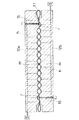
前記金型(12a)(12b)には、前記合成樹脂製塀板用パネル(1)の立体模様部(2)と、隣接する該立体模様部間の前記帯状平坦部(3)と、合じゃくり状にずらし出された各縁部の継手部(4)との各部分に対応するキャビティー(13a)(13b)を有し、前記各キャビティー(13a)(13b)の外周縁にはシート挟着部(14a)(14b)を、また前記各キャビティー(13a)(13b)の内面と前記シート挟着部(14a)(14b)には、外部の吸引装置(s)に通じる微細な多数の空気吸引孔(h)と、さらに前記継手部(4)に対応するキャビティー(13a)(13b)の各平坦部(f)には進退自在な少なくとも1個以上の空気加圧装置(図示省略)に通じる加圧空気導入ノズル(15)とが設置されており、さらにまた前記各帯状平坦部(3)の少なくとも1部において表裏両層を接合するための隆起部(m)が形成されている。
【0025】
合成樹脂製塀板用パネル(1)を成形するには、前記金型(12a)(12b)を用い、まず可塑化した円筒状のパリソン(11)を偏平化させて前記金型(12a)(12b)間に垂下させ、図9に示すように、両金型(12a)(12b)を閉じながら、空気吸引孔(h)から負圧吸引しつつ前記熱可塑性合成樹脂の表裏両層を前記シート挟着部(14a)(14b)で挟着して接合し、同時に両金型(12a)(12b)のキャビティー(13a)(13b)に吸着させながら、前記加圧空気導入ノズル(15)を前記熱可塑性合成樹脂の両層間に侵入させて加圧空気を導入し、キャビティーの前記隆起部(m)では前記熱可塑性合成樹脂の表裏両層を接合させて、それ以外の部分では全空間を実質的に連通状態にして中空状とする。
【0026】
しかるのち、中空状の成形体を型内冷却し、前記加圧空気導入ノズル(15)を後退させて中空成形体を取出し、その外周を前記立体模様部(2)に沿って切除することにより、合成樹脂製塀板用パネル(1)を得る。
【0027】
この発明の製造方法において、前記第1の発明の好ましい実施態様である前記合成樹脂製塀板用パネル(1)を成形するには、これらを複数連結するための構造に対して、図5(イ)(ロ)に示すように、ボルト挿入孔(5a)(5b)および板状ナット(6a)(6b)を設けるが、ボルト挿入孔(5a)(5b)に対してはこれに対応する突状片(図示省略)をキャビティー(13a)(13b)のいずれか一方の所定位置に設置して、これにより成形時に同時成形し、また板状ナット(6a)(6b)に対しては、図5(ロ)のように、継手部(4)に対応する前記突条片を設置した側のキャビテイー(13a)または(13b)にマグネット(g)を装置し、これに前記板状ナット(6a)(6b)を仮止めして、成形時に前記板状ナット(6a)(6b)の固定用舌片(j)を可塑化状態の合成樹脂に埋没させて、継手部(4)と面一となるように装着する。
【0028】
なお、通常のボルトナット形式により連結する構造の前記変形態様としての合成樹脂製塀板用パネル(1)を成形するには、前記ボルト挿入孔(5a)(5b)と同様のボルト挿入孔を、図5(イ)と同様の形態で裏層の立体模様部(2)の頂部にも設けるのであるから、裏層の当該ボルト挿入孔に対応する突状片(図示省略)を裏層に対応するキャビティー(13a)(13b)のいずれか他方の所定位置にも設置して成形すればよい。従って、この場合は前記板状ナット(6a)(6b)を装着しないから、前記マグネット(g)の装置は不要となる。
【0029】
また、上記の製造方法において、成形中に熱可塑性合成樹脂の両層間に加圧空気を導入するために、合成樹脂製塀板用パネル(1)の表裏両層の継手部(4)に、加圧空気導入ノズル(15)が貫通した挿通孔(r)ができるが、当該挿通孔(r)は中空成形体内部を外部と連通させるための通気孔として残す。前記挿通孔(r)は、これを通して中空成形体内外の空気が自由に出入することができるから、合成樹脂製塀板用パネル(1)が外気温度の変化により膨脹収縮を起こし変形するのを防止する作用をする。
【0030】
この発明による合成樹脂製塀板用パネル(1)の製造方法は、基本的には通常の成形装置により通常の手順で成形されるものであるが、上記のように熱可塑性合成樹脂を可塑化した円筒状のパリソン(11)を、合成樹脂製塀板用パネル(1)の表裏両層に形成する割竹様の立体模様部(2)と、隣接する該立体模様部間の帯状平坦部(3)と、合じゃくり状にずらし出された各縁部の継手部(4)との各部分に対応するキャビティーを有した一対の金型により中空成形体を成形する工程と、切除する工程のみで、合成樹脂製塀板用パネル(1)を製造することができ、形状が一様なパネルを容易に量産することができる。
【0031】
なお、この発明による製造方法においては、前記金型(12a)(12b)の構造を変更し、合成樹脂製塀板用パネル(1)を複数枚同時に成形できるようにすることもできる。
【0032】
【実施例】
まず、対象とする合成樹脂製塀板用パネルの形状として、図1に示すとおりの外観であって、断面における曲率半径が約26mm、割り幅が45mm、長さ610mmの割竹様凸条よりなる立体模様部(2)を12条と、隣接する前記立体模様部との間に、中間の補強部(3a)に相当する部分では幅約4mm、その他の部分では幅5mmの帯状平坦部(3)を11条とを表層に形成し、裏層には表層と同形状、同数の前記立体模様部(2)と帯状平坦部(3)とを、左方向に前記立体模様部(2)の1列分を、また上方向に30mmを、表裏両層で合じゃくり状にずらし、ずらし出された各縁部の前記立体模様部(2)の裏面となる対応層には平坦な継手部(4)を形成し、さらに前記中間の補強部(3a)に相当する部分では表裏両層を接合した構造を採用した。
【0033】
また、連結用のボルト挿入孔(5a)を、表層右端の立体模様部(2)の頂部に上下端部から夫々70mmの位置に2個、さらにボルト挿入孔(5b)を右端から3条目および左端から2条目の立体模様部(2)の下端から15mmの位置に各1個設けるものとし、さらに表層の前記継手部(4)に他の当該パネルの前記ボルト挿入孔(5a)に対応する位置に、厚さ1.8mm、幅18mm、長さ42mmの鉄板を固定用舌片(j)を板金加工し、中央に雌ネジを形成した板状ナット(6a)(6b)を夫々設けるものとした。
【0034】
つぎに、合成樹脂製塀板用パネルの材料としてAES樹脂を採用し、通常のブロー成形法の押出装置を用いて直径約50cm、厚さ約5mmのパリソン(11)を押出し、図7および図8に示すように、前記の構成の合成樹脂製塀板用パネルにおける、立体模様部(2)、帯状平坦部(3)および継手部(4)に対応するキャビテー(13a)(13b)を有する一対の金型(12a)(12b)を採用し、前記金型(12a)(12b)のいずれか一方に、前記ボルト挿入孔(5a)(5b)に対応する位置に突状片と、前記板状ナット(6a)(6b)を仮止めしたのち、該金型(12a)(12b)間に前記パリソン(11)を偏平化して垂下させ、両金型(12a)(12b)を閉じ、空気吸引孔(h)からの負圧吸引、加圧空気導入ノズル(15)の加圧空気の導入操作を行って、常法の手順により成形した。さらに、中空成形体を金型(12a)(12b)を開いて取り出し、その外周の立体模様部(2)に沿って切除して、合成樹脂製塀板用パネル(1)を得た。
【0035】
上記で得られた合成樹脂製塀板用パネル(1)は、剛性が高く、一方の層にはボルト挿入孔も板状ナットも存在せず美観に優れ、また表裏両層の立体模様部(2)は帯状平坦部(3)と相俟って顕著な立体感を呈するものであった。
【0036】
【発明の効果】
以上のように、この発明の第1の発明である合成樹脂製塀板用パネルは、表裏両層に複数の割竹様凸条よりなる立体模様部を並列状に形成し外周端縁を接合した熱可塑性合成樹脂製の中空成形体であって、隣接する前記立体模様部を互いに一定幅の帯状平坦部を介して形成し、かつ表裏両層を左右方向に前記立体模様部の1列分を、上下方向に所定幅分を夫々合じゃくり状にずらし、ずらし出された各縁部の前記立体模様部の対応層には平坦な継手部を形成するとともに、前記各帯状平坦部の少なくとも1部において表裏両層を接合した補強部を形成することによって、中空成形体内の空間を実質的に連通状態としたから、重量が軽量であるとともに全体の剛性が高く強度に優れるという効果を有し、また帯状平坦部の存在により、立体模様部が直接に連設された従来のこの種パネルに比較して、各立体模様部の立体的視覚効果をより高めることができ、顕著な立体感を呈する外観品質に優れた効果を有するものとなる。
【0037】
また、この発明の合成樹脂製塀板用パネルは、前記平坦状継手部で互いに連結する一方の中空パネルの前記立体模様部に連結用ボルトを挿入するためのボルト挿入孔を複数箇所設け、他方の中空パネルの前記平坦状継手部に前記ボルト挿入孔に対応し固定用舌片を有する板状ナットを前記平坦状継手部と面一となるように装着したから、合成樹脂製塀板用パネル同士の連結が簡単容易であるという効果があり、しかも1枚の合成樹脂製塀板用パネルの表裏いずれかの層にボルト挿入孔と板状ナットとを設けたから、他方の層は立体模様部と帯状平坦部とからのみ構成されていることとなり視覚上の実用面として、外観的に違和感のない、美麗な外観を呈するものとなるという利点がある。
【0038】
さらに、この発明の第2の発明である合成樹脂製塀板用パネルの製造方法は、割竹様の凸状の前記立体模様部と、隣接する該立体模様部間の前記帯状平坦部と、合じゃくり状にずらし出された各縁部の継手部との各部分に対応するキャビティーを有し、前記各キャビティーの外周縁にはシート挟着部を、また前記各キャビティーの内面と前記シート挟着部には微細な多数の空気吸引孔と、さらに前記継手部に対応するキャビティーの各平坦部には進退自在な少なくとも1個以上の加圧空気導入ノズルとが設置されており、さらにまた前記各帯状平坦部の少なくとも1部において表裏両層を接合するための隆起部が形成された左右一対の金型を用い、該金型間に熱可塑性合成樹脂を可塑化した円筒状のパリソンを両金型の面方向に偏平化させて垂下させ、両金型を閉じながら前記空気吸引孔から負圧吸引しつつ前記熱可塑性合成樹脂の表裏両層を前記シート挟着部で挟着して接合するとともに、両金型のキャビティーに吸着させながら、前記加圧空気導入ノズルを前記熱可塑性合成樹脂の両層間に侵入させて加圧空気を導入し、キャビティーの前記隆起部では前記熱可塑性合成樹脂の両層を接合する以外は、全空間を実質的に連通状態にして中空状としたのち、前記加圧空気導入ノズルを後退させて中空成形体を取出す工程と、前記立体模様部の外周を切除する工程とよりなる製造方法であるから、工程が短縮されるのみならず形状の一様なパネルを容易にかつ安価に量産することができるという効果がある。
【0039】
さらにまた、この発明の合成樹脂製塀板用パネルの製造方法は、前記平坦継手部に対応するキャビティーの所定部分であって、前記ボルト挿入孔に対応する位置にマグネットを装置し、該マグネットに前記連結用板状ナットを仮止めしたのち、中空成形体を成形することとしたから、従来のこの種パネルのように成形後に連結用具を取付けたり連結用の孔を設ける必要がなく、連結用板状ナットを所定の位置に正確にかつ安価に取付けることができるという利点がある。
【図面の簡単な説明】
【図1】 この発明の合成樹脂製塀板用パネルを示す斜視図である。
【図2】 この発明の合成樹脂製塀板用パネルを示す平面図である。
【図3】 この発明の合成樹脂製塀板用パネルの切断端面図であり、図3(イ)は図2のA−A線切断端面図、図3(ロ)は同じくB−B線切断端面図、図3(ハ)は同じくC−C線切断端面図である。
【図4】 複数の合成樹脂製塀板用パネルの連結設置状態を説明するための概念図である。
【図5】 合成樹脂製塀板用パネルの連結手段を示す断面図であり、図5(イ)はボルト挿入孔、図5(ロ)は連結用板状ナットを示す。
【図6】 合成樹脂製塀板用パネルの設置状態を示す概念図である。
【図7】 この発明の合成樹脂製塀板用パネルの製造方法を説明するための概念図であって、成形工程の開始時における成形装置の縦断面図である。
【図8】 この発明の合成樹脂製塀板用パネルの製造方法を説明するための概念図であって、成形工程の開始時における成形装置の横断面図である。
【図9】 この発明の合成樹脂製塀板用パネルの製造方法を説明するための概念図であって、成形工程の最中における成形装置の横断面図である。
【符号の説明】
1、1n…合成樹脂製塀板用パネル
2…立体模様部
3…帯状平坦部
3a…補強部
4、4n…継手部
5…ボルト
5a、5b…ボルト挿入孔
6a、6b…板状ナット
11…パリソン
12a、12b…金型
13a、13b…キャビティー
14a、14b…シート挟着部
15…加圧空気導入ノズル
f…平坦部
g…マグネット
h…空気吸引孔
j…固定用舌片
m…隆起部
n…挿通孔[0001]
BACKGROUND OF THE INVENTION
TECHNICAL FIELD The present invention relates to a synthetic resin siding panel used for garden fences and fences and a method for manufacturing the same.
[0002]
[Prior art]
Traditionally, Japanese-style gardens, etc., have been made of natural bamboo split bamboo, which is mounted in parallel on a frame made up of a plurality of pillars and trunk edges. Bamboo fences that have been sandwiched in a row in parallel and fixed with a rope or the like have long been awarded for fences and fences.
[0003]
However, bamboo and fences made from natural bamboo give elegance, but not only do they require a high level of skill and labor, but they are also exposed to the natural environment such as sunlight, wind and rain, and temperature changes. Discoloration, corrosion, decay and inferior durability. And recently, it has become rather expensive.
[0004]
In recent years, in order to eliminate the disadvantages of natural bamboo as described above, a synthetic resin was used to imitate the shape and color of the natural bamboo so that the texture of the natural bamboo can be externally incorporated, and many split bamboos were connected and integrated. It is known to have a panel body that has a finished appearance, makes it easy to work as a fence or fence, and is highly durable. For example, in Japanese Patent No. 2527146 (Known Example 1), a panel-shaped main body is formed by connecting a large number of split bamboo parts in the shape of an arc of a cross section made of a synthetic resin having a natural bamboo color in the width direction. In addition, a synthetic resin is provided in which one or both of the side ends of the panel-shaped main body is provided with a concave groove portion having a thickness width of the panel main body along the side end, and a connecting portion is integrally stretched outside the concave groove portion. Bamboo panels are disclosed, and Japanese Laid-Open Patent Publication No. 63-161273 (Known Example 2) has the same color as that of the synthetic resin bamboo panel of the above-mentioned Known Example 1, and is colored in the color of natural bamboo. There is disclosed a panel body in which split bamboo portions made of a synthetic resin and formed into a long and narrow split bamboo shape facing both front and back surfaces are continuously formed in the short direction.
[0005]
However, when the panels of the known example 1 are connected to each other, they can be connected simply by accommodating and placing the side edges of the other panels in the concave groove portions, so that the panels can be connected easily and reliably. Although it has the advantage that it can be done and the seam is almost inconspicuous and the appearance is beautiful, the panel itself is designed for one side, and when it is used as a double-sided fence or fence, The individual panels must be attached to the edges from both sides with ropes and nails, and the construction of the fences and fences is not easy and easy.
[0006]
Further, since the panel of the above-mentioned known example 2 can be connected by forming convex portions and concave grooves which are fitted to each other on both side ends or by providing protruding pieces facing each other, it is easy and reliable to connect the panels. In addition, it has the same advantages as the prior art example 1 in that the seam is almost inconspicuous and the appearance is beautiful, and in addition, it is constructed in the field compared to the prior art example 1 in that split bamboo shapes are formed on both sides of the panel. Can be said to be a little easier. However, on-site construction is still insufficient to be simple and easy, and the upper panel itself has a continuous shape with a portion where both sides bulge in a circular arc shape and a valley-like portion, and is solid. Therefore, there is a limit in reducing the thickness in securing the strength of the panel, which inevitably increases the weight and disadvantageously increases the material cost.
[0007]
[Problems to be solved by the invention]
The present invention solves such conventional drawbacks, and can easily and securely connect this kind of synthetic resin siding panel, and can be reliably and firmly constructed, and exhibits a remarkable three-dimensional effect. An object of the present invention is to provide a synthetic resin plate panel having a structure excellent in appearance quality and a method for manufacturing the same.
[0008]
[Means for Solving the Problems]
That is, the first invention of the present invention is a hollow molded body made of a thermoplastic synthetic resin in which a three-dimensional pattern portion composed of a plurality of split bamboo-like ridges is formed in parallel on both front and back layers and the outer peripheral edges are joined. The adjacent three-dimensional pattern portions are formed through belt-shaped flat portions having a constant width, and both the front and back layers are aligned in the left-right direction for one row of the three-dimensional pattern portions, and the predetermined width in the vertical direction. A flat joint portion is formed in the corresponding layer of the three-dimensional pattern portion of each edge portion shifted in a cut-out shape, and a reinforcing portion in which both front and back layers are joined in at least one portion of each belt-like flat portion The gist of the panel for synthetic resin is that the space in the hollow molded body is substantially in communication by forming.
[0009]
According to a second aspect of the present invention, there is provided a manufacturing method for manufacturing the synthetic resin board panel according to
[0010]
Hereinafter, a method for producing a synthetic resin board panel according to the first aspect of the present invention and a method of manufacturing the synthetic resin board panel according to the second aspect of the invention will be described with reference to the drawings.
[0011]
First, as shown in FIG. 1 and FIG. 2, the synthetic resin board panel according to the first aspect of the present invention is a synthetic resin board panel (1) having a plurality of split bamboo-like ridges on the surface layer and the back layer. A hollow molded body made of a thermoplastic synthetic resin in which a three-dimensional pattern portion (2) to be formed is formed in parallel via a strip-shaped flat portion (3) having a constant width (w) and the outer peripheral edges are joined to form a hollow shape. Consists of. Then, both the front and back layers are shifted in the left-right direction by one row of the three-dimensional pattern portion (2), and the predetermined width is shifted in the vertical direction, respectively, and the three-dimensional pattern portion at each shifted edge is shifted. The corresponding layer (4a) (4b) of (2) is formed into a flat shape to form a joint portion (4), and at least one portion of each of the belt-like flat portions (3) is joined to the reinforcing portion (3a ) To make the space in the hollow molded body substantially communicated.
[0012]
The outer panel (1) made of synthetic resin looks like a hollow molded body in which each of the three-dimensional patterns (2) is individually formed as an independent space, but its internal structure is shown in FIG. As is apparent from the end faces of the respective cut portions shown in (a) to (c), in each three-dimensional pattern portion (2), the reinforcing portion (3a) of the belt-like flat portion (3) in which the front and back surfaces are joined, Most of the hollow molded body excluding the outer peripheral edgeAs shown in FIG.It has a structure that is substantially in communication.
[0013]
Here, the strip-shaped flat portion (3) disposed between the three-dimensional pattern portions (2) visually recognizes the space between the three-dimensional pattern portions (2) themselves due to the presence of the strip-shaped flat portion (3). And the reinforcing part (3a)Figure 3 (b)As shown by the above, since the front and back layers are joined by a part of the belt-like flat part (3), it serves to improve the rigidity of the panel (1) as a whole.
[0014]
In addition, as shown in FIG. 4, a preferred embodiment of the first invention of the present invention is that other synthetic materials are horizontally or vertically moved at the shifted edges of the synthetic resin panel (1). In order to connect the resin board panel (1n), bolt insertion holes (5a) (5b) are formed at the top of the three-dimensional pattern part (2) at a position corresponding to the joint part (4n) of the panel (1n). Furthermore, plate-like nuts (6a) and (6b) are placed at positions corresponding to the respective bolt insertion holes (5n) of the other synthetic resin plate panel (1n) in the joint portion (4). It is set as the synthetic resin board panel (1) of the structure mounted in the state embedded so that it might become flush with (4).
[0015]
In this case, the bolt insertion holes (5a) (5b) and plate-like nuts (6a) (6b) of the synthetic resin board panel (1) are all provided on the surface layer, Not provided. Therefore, the back layer is composed only of the three-dimensional pattern part (2) and the belt-like flat part (3). If this layer is used as a practical visual aspect, there is no sense of incongruity in appearance and a more beautiful appearance. Give a good vision.
[0016]
The bolt insertion holes (5a) and (5b) and the plate-like nuts (6a) and (6b) are formed simultaneously with the molding of the hollow molded body, as will be described later in the manufacturing method. ) (5b) is formed in a cylindrical shape recessed from the top of the three-dimensional pattern portion (2) as shown in FIG. 5 (a), and the plate nuts (6a) and (6b) are shown in FIG. As shown, plate-shaped nuts (6a) and (6b) are connected to the flat joint portion (4), and the plastic plate-like synthetic resin is entangled with the fixing tongue piece (j). Wear so that they are flush with each other. In addition, (12) is a metal mold | die used at the time of shaping | molding, (g) is a magnet for temporary fixing of the plate-shaped nut (6a) (6b) installed in the predetermined position of this metal mold | die.
[0017]
When actually constructing the panel (1) made of synthetic resin according to the present invention, as shown in FIG. 4, the other panel (1n) installed adjacent to the left or right or up and down, both flat The joint (4)And (4n)When connecting them with bolts (5) and installing them on the pillars of the framework, as shown in FIG. 6, the panel (1)And (1n)The joint part (4)And (4n)May be opposed to the column (p) and connected in accordance with a commonly used conventional method.
[0018]
Further, in the case of the synthetic resin board panel (1) according to the present invention, when connecting the upper and lower parts, the body edge for attaching the panel between the columns (p) is not required as in the prior art, and the joint Since the structure of each part including the part (4) is formed in a uniform shape with any hollow molded body, alignment can be performed reliably. Further, as shown in FIG. 6, the upper edge of the installed synthetic resin board panel (1) has a mode in which the joint (4) is covered with, for example, the coping (q), and is opposed to this. What is necessary is just to connect according to a conventional method.
[0019]
In the present invention, in addition to the above-described preferred embodiment related to the first invention, as a modification, a position where the plate-like nuts (6a) and (6b) of the synthetic resin board panel (1) are mounted. Further, the plate-like nuts (6a) and (6b) are replaced with bolt insertion holes similar to the bolt insertion holes (5a) and (5b), and the three-dimensional pattern portion of the back layer is formed in the same form as in FIG. 2), it is also provided on the top of the synthetic resin board panel (1) and (1n), and bolts are inserted into the bolt insertion holes (5a) and (5b) corresponding to each other by a normal bolt nut type. It is also possible to have a structure in which the nuts are connected to each other by inserting the nuts into the other side and tightening bolts (not shown) on the other. In this case, although the appearance quality is slightly inferior to the case where the plate-like nuts (6a) and (6b) are used, it is not necessary to attach a nut having a special shape such as the plate-like nuts (6a) and (6b).
[0020]
Since the structure of the synthetic resin siding panel (1) according to the present invention is composed of a hollow molded body, it is light in weight and reinforced to each of the belt-like flat portions (3). Since the portion (3a) is formed, the rigidity is high, and since all the spaces in the hollow molded body are in a substantially communicating state, the communication through the outside to at least one location of the hollow molded body is possible. If pores are provided, deformation due to expansion and contraction does not occur regardless of changes in the outside air temperature. In this case, as the vent hole, an insertion hole formed by a pressurized air introduction nozzle of a molding apparatus shown in a molding method described later can be used as it is.
[0021]
Examples of the synthetic resin used for the synthetic resin board panel (1) of the present invention include AES resin (acrylonitrile-ethylenepropylene rubber-styrene copolymer), PVC resin (polyvinyl chloride or polyvinyl chloride). A thermoplastic synthetic resin such as a vinyl chloride copolymer as a main component and a PP resin (polypropylene) is used.
[0022]
Next, a method for producing the synthetic resin siding panel according to the second aspect of the present invention will be described. In the manufacturing method described below, a parison obtained by extruding a thermoplastic synthetic resin plasticized from a die head into a cylindrical shape from an extrusion device is suspended between a pair of left and right molds and the mold is closed. Adopt molding methodRuHowever, as a method for producing a synthetic resin board panel according to the present invention, two sheets of a plastic synthetic resin that has been plasticized instead of the parison and extruded in parallel at regular intervals are molded. The method of doing can also be employ | adopted.
[0023]
7 and 8, (11) is extruded into a cylindrical shape from an upper extrusion device (not shown), and is flattened in the surface direction of the mold between a pair of left and right molds (12a) and (12b). It is a plasticized parison made of a thermoplastic synthetic resin that hangs down.
[0024]
The molds (12a) and (12b) include a three-dimensional pattern portion (2) of the synthetic resin board panel (1), and a belt-like flat portion (3) between adjacent three-dimensional pattern portions. There are cavities (13a) and (13b) corresponding to the joint portions (4) of the respective edges that are shifted out in a jerky shape, and the outer peripheries of the respective cavities (13a) and (13b) Is connected to an external suction device (s) through the sheet sandwiching portions (14a) and (14b), and the inner surfaces of the cavities (13a) and (13b) and the sheet sandwiching portions (14a) and (14b). At least one or more air pressurizations that can be advanced and retracted in a large number of fine air suction holes (h) and flat portions (f) of the cavities (13a) and (13b) corresponding to the joint portions (4). And a pressurized air introduction nozzle (15) leading to the device (not shown). Cage, and is furthermore the raised portion for joining the front and back both layers at least one part (m) is formed in each belt-like flat portion (3).
[0025]
To mold the synthetic resin panel (1), the mold (12a) (12b) is used. First, the plasticized cylindrical parison (11) is flattened to form the mold (12a). As shown in FIG. 9, both the front and back layers of the thermoplastic synthetic resin are drawn while negatively sucking from the air suction holes (h) while closing both molds (12 a) and (12 b). The compressed air introduction nozzle (14a) and (14b) are sandwiched and joined together, and at the same time adsorbed to the cavities (13a) and (13b) of both molds (12a) and (12b). 15) is introduced into both layers of the thermoplastic synthetic resin, and pressurized air is introduced, and the front and back layers of the thermoplastic synthetic resin are joined at the raised portion (m) of the cavity, and the other portions Then, the entire space is made substantially in a communicating state and is hollow.
[0026]
Thereafter, the hollow molded body is cooled in the mold, the pressurized air introduction nozzle (15) is moved backward to take out the hollow molded body, and the outer periphery thereof is cut out along the three-dimensional pattern portion (2). A synthetic resin board panel (1) is obtained.
[0027]
In the manufacturing method of this invention, in order to shape | mold the said synthetic resin board panel (1) which is a preferable embodiment of the said 1st invention, with respect to the structure for connecting these two or more, FIG. (B) As shown in (b), bolt insertion holes (5a) (5b) and plate-like nuts (6a) (6b) are provided, which correspond to the bolt insertion holes (5a) (5b). A projecting piece (not shown) is installed at a predetermined position in either one of the cavities (13a) and (13b), thereby simultaneously molding at the time of molding, and plate-like nuts (6a) and (6b).InOn the other hand, as shown in FIG. 5 (b), the magnet (g) is installed in the cavity (13a) or (13b) on the side where the protruding piece corresponding to the joint (4) is installed, Temporarily fix plate nuts (6a) and (6b)Of the plate-like nuts (6a) (6b)Fixing tongue (j)TheIt is buried in a plasticized synthetic resin so as to be flush with the joint (4).
[0028]
In addition, in order to shape | mold the synthetic resin board panel (1) as a deformation | transformation aspect of the structure connected with a normal bolt nut type, the bolt insertion hole similar to the said bolt insertion hole (5a) (5b) is used. 5 (a), it is also provided on the top of the three-dimensional pattern portion (2) of the back layer, so that a protruding piece (not shown) corresponding to the bolt insertion hole of the back layer is provided on the back layer. What is necessary is just to install in the other predetermined position of the corresponding cavity (13a) (13b), and to shape | mold. Therefore, in this case, since the plate-like nuts (6a) and (6b) are not attached, the device for the magnet (g) becomes unnecessary.
[0029]
Further, in the above manufacturing method, in order to introduce pressurized air between both layers of the thermoplastic synthetic resin during molding, in the joint portion (4) of both the front and back layers of the synthetic resin board panel (1), An insertion hole (r) through which the pressurized air introduction nozzle (15) passes is formed, but the insertion hole (r) is left as a ventilation hole for communicating the inside of the hollow molded body with the outside. The insertion hole (r) allows the air inside and outside the hollow molding body to freely enter and exit through the insertion hole (r), so that the synthetic resin wall panel (1) is deformed due to expansion / contraction due to a change in the outside air temperature. It works to prevent it.
[0030]
The method for producing a synthetic resin board panel (1) according to the present invention is basically formed by a normal molding apparatus in a normal procedure, but plasticizing a thermoplastic synthetic resin as described above. The split bamboo-like three-dimensional pattern part (2) for forming the cylindrical parison (11) formed on both the front and back layers of the synthetic resin board panel (1), and a belt-like flat part between the adjacent three-dimensional pattern parts (3) and a step of forming a hollow molded body with a pair of molds having cavities corresponding to respective portions of the joint portions (4) of the respective edge portions shifted out in a joint shape, and excision Only by the process of performing, the panel (1) for synthetic resin boards can be manufactured, and a panel with a uniform shape can be mass-produced easily.
[0031]
In addition, in the manufacturing method by this invention, the structure of the said metal mold | die (12a) (12b) can be changed, and it can also be made to shape | mold a plurality of synthetic resin board panels (1) simultaneously.
[0032]
【Example】
First, as the shape of the target synthetic resin board panel, the appearance is as shown in FIG.26A three-dimensional pattern consisting of split bamboo-like ridges with a mm, split width of 45 mm, and a length of 610 mm (2) And the adjacent three-dimensional pattern portion between the strip corresponding flat portion (3) having a width of about 4 mm in the portion corresponding to the intermediate reinforcing portion (3a) and 5 mm in the other portion. Is formed on the surface layer, and the back layer has the same shape and the same number of the three-dimensional pattern portions (2) And the belt-like flat portion (3) in the left direction, the three-dimensional pattern portion (2) For one row, 30mm upward, front and backBothA flat joint portion (4) is formed on the corresponding layer which is the back surface of the three-dimensional pattern portion (2) of each edge that is shifted out, and the intermediate reinforcing portion ( In the part corresponding to 3a), both front and back layersTheAdopted a joined structure.
[0033]
Further, two bolt insertion holes (5a) for connection are provided at the top of the three-dimensional pattern portion (2) at the right end of the surface layer at positions 70 mm from the upper and lower ends, respectively, and a bolt insertion hole (5b) is provided at the third line from the right end and One piece is provided at a
[0034]
Next, AES resin was adopted as the material for the synthetic resin board panel, and a parison (11) having a diameter of about 50 cm and a thickness of about 5 mm was extruded using an extrusion apparatus of a normal blow molding method. As shown in FIG. 8, the synthetic resin siding panel having the above-described configuration has cavities (13a) and (13b) corresponding to the three-dimensional pattern portion (2), the belt-like flat portion (3), and the joint portion (4). A pair of molds (12a) and (12b) are employed, and one of the molds (12a) and (12b) has a protruding piece at a position corresponding to the bolt insertion hole (5a) and (5b), After temporarily fixing the plate-like nuts (6a) and (6b), the parison (11) is flattened and suspended between the molds (12a) and (12b), and both molds (12a) and (12b) are closed. Negative pressure suction from the air suction hole (h), pressurized air guide Performing introduction operation of pressurized air nozzle (15), it was molded by the procedure of a conventional method. Further, the hollow molded body was taken out by opening the molds (12a) and (12b), and cut out along the three-dimensional pattern portion (2) on the outer periphery thereof to obtain a synthetic resin board panel (1).
[0035]
The synthetic resin board panel (1) obtained above has high rigidity, has no bolt insertion holes or plate nuts in one layer, and has an excellent aesthetic appearance. 2) presents a remarkable three-dimensional effect in combination with the belt-like flat portion (3).
[0036]
【The invention's effect】
As described above, the synthetic resin board panel according to the first aspect of the present invention has a three-dimensional pattern portion composed of a plurality of split bamboo-like ridges formed in parallel on both front and back layers, and joined to the outer peripheral edge. A hollow molded body made of thermoplastic synthetic resin, in which the adjacent three-dimensional pattern portions are formed through belt-like flat portions having a constant width, and both front and back layers are formed in one row of the three-dimensional pattern portions in the left-right direction. Are shifted in the vertical direction by a predetermined width, respectively, and a flat joint portion is formed on the corresponding layer of the three-dimensional pattern portion of each shifted edge portion, and at least each of the belt-like flat portions. By forming the reinforcing part in which the front and back layers are joined in one part, the space in the hollow molded body is substantially in a communicating state, so that the weight is light and the overall rigidity is high and the strength is excellent. The three-dimensional pattern Compared with this type of conventional panel, which is directly connected to each other, the three-dimensional visual effect of each three-dimensional pattern portion can be further enhanced, and it has an excellent appearance quality with a remarkable three-dimensional effect. .
[0037]
In addition, the synthetic resin board panel according to the present invention is,in frontA plurality of bolt insertion holes for inserting connecting bolts are provided in the three-dimensional pattern portion of one hollow panel that is connected to each other by the flat joint portion, and the bolt insertion hole is provided in the flat joint portion of the other hollow panel. Since a plate-like nut having a fixing tongue piece is mounted so as to be flush with the flat joint portion, there is an effect that it is easy and easy to connect the synthetic resin plate panels, and Since bolt insertion holes and plate-like nuts are provided on either the front or back layer of a single synthetic resin board panel, the other layer is composed of only a three-dimensional pattern part and a belt-like flat part. As an upper practical aspect, there is an advantage that it has a beautiful appearance with no discomfort in appearance.
[0038]
Furthermore, the method for producing a synthetic resin board panel according to the second aspect of the present invention comprises the split bamboo-like convex three-dimensional pattern portion, and the belt-like flat portion between the adjacent three-dimensional pattern portions, A cavity corresponding to each portion of the joint portion of each edge that is shifted out like a joint; a sheet sandwiching portion on the outer peripheral edge of each cavity; and an inner surface of each cavity And a plurality of fine air suction holes in the sheet sandwiching portion, and at least one or more pressurized air introduction nozzles that can move forward and backward are installed in each flat portion of the cavity corresponding to the joint portion. Furthermore, a cylinder in which a thermoplastic synthetic resin is plasticized between the molds, using a pair of left and right molds in which raised portions for joining the front and back layers are formed in at least one part of each belt-like flat part. Flat parison in the direction of both mold surfaces The front and back layers of the thermoplastic synthetic resin are sandwiched and joined at the sheet sandwiching portion while suctioning a negative pressure from the air suction hole while closing both molds, and in the cavities of both molds. While adsorbing, the pressurized air introduction nozzle is penetrated between both layers of the thermoplastic synthetic resin to introduce pressurized air, and the two layers of the thermoplastic synthetic resin are joined at the raised portion of the cavity. A manufacturing method comprising the steps of: removing the hollow molded body by retracting the pressurized air introduction nozzle after making the entire space substantially in a communicating state, and removing the outer periphery of the three-dimensional pattern portion Therefore, there is an effect that not only the process is shortened but also a panel having a uniform shape can be easily mass-produced at a low cost.
[0039]
Furthermore, the manufacturing method of the synthetic resin board panel according to the present invention is as follows.,in frontA magnet is installed at a position corresponding to the bolt insertion hole, which is a predetermined portion of the cavity corresponding to the flat joint portion, and the hollow plate is formed by temporarily fixing the connecting plate nut to the magnet. Therefore, there is no need to attach a connecting tool or provide a connecting hole after molding as in the case of this type of conventional panel, and the connecting plate-like nut can be attached to a predetermined position accurately and inexpensively. There is an advantage.
[Brief description of the drawings]
FIG. 1 is a perspective view showing a synthetic resin board panel according to the present invention.
FIG. 2 is a plan view showing a synthetic resin board panel according to the present invention.
3 is a cut end view of a synthetic resin board panel according to the present invention, FIG. 3 (a) is an AA cut end view of FIG. 2, and FIG. 3 (b) is a BB cut similarly. The end view and FIG. 3C are also end views taken along the line CC.
FIG. 4 is a conceptual diagram for explaining a connection and installation state of a plurality of synthetic resin wall panels.
FIG. 5 is a cross-sectional view showing a connecting means for a synthetic resin board panel, FIG. 5 (a) shows a bolt insertion hole, and FIG. 5 (b) shows a connecting plate nut.
FIG. 6 is a conceptual diagram showing an installation state of a synthetic resin board panel.
FIG. 7 is a conceptual diagram for explaining a method for manufacturing a synthetic resin siding panel according to the present invention, and is a longitudinal sectional view of a molding apparatus at the start of a molding process.
FIG. 8 is a conceptual diagram for explaining a method for manufacturing a synthetic resin board panel according to the present invention, and is a cross-sectional view of a molding apparatus at the start of a molding process.
FIG. 9 is a conceptual diagram for explaining a method for manufacturing a synthetic resin board panel according to the present invention, and is a cross-sectional view of a molding apparatus during a molding process.
[Explanation of symbols]
1, 1n ... Synthetic resin board panel
2 ... Solid pattern part
3 ... strip flat part
3a ... Reinforcing part
4, 4n ... Joint part
5 ... Bolt
5a, 5b ... Bolt insertion hole
6a, 6b ... Plate-shaped nut
11 ... Parison
12a, 12b ... mold
13a, 13b ... cavity
14a, 14b ... sheet clamping part
15 ... Pressurized air introduction nozzle
f ... Flat part
g ... Magnet
h ... Air suction hole
j ... tongue for fixing
m ... Uplift
n ... insertion hole
Claims (2)
前記平坦状継手部で互いに連結する一方の中空パネルの前記立体模様部に連結用ボルトを挿入するためのボルト挿入孔を複数箇所設け、他方の中空パネルの前記継手部に前記ボルト挿入孔に対応し固定用舌片を有する板状ナットを前記平坦状継手部と面一となるように装着したことを特徴とする合成樹脂製塀板用パネル。A hollow molded body made of a thermoplastic synthetic resin in which a three-dimensional pattern portion composed of a plurality of split bamboo-like ridges is formed in parallel on both front and back layers and the outer peripheral edges are joined, and the adjacent three-dimensional pattern portions are fixed to each other Each of the edges formed by shifting the front and back layers in the horizontal direction by one row of the three-dimensional pattern portion in the left-right direction and the predetermined width in the up-down direction in the form of a joint Forming a flat joint part in the corresponding layer of the three-dimensional pattern part of the part, and forming a reinforcing part that joins both the front and back layers in one part of each belt-like flat part , thereby substantially reducing the space in the hollow molded body In communication ,
A plurality of bolt insertion holes for inserting connecting bolts are provided in the three-dimensional pattern portion of one hollow panel that is connected to each other by the flat joint portion, and the bolt insertion hole corresponds to the joint portion of the other hollow panel. A synthetic resin scissor panel , wherein a plate-like nut having a fixing tongue piece is mounted so as to be flush with the flat joint portion .
前記平坦継手部に対応するキャビティーの所定部分であって、前記ボルト挿入孔に対応する位置にマグネットを装置し、該マグネットに前記板状ナットを仮止めしたのち、中空成形体を成形するものとした合成樹脂製塀板用パネルの製造方法。A predetermined portion of a cavity corresponding to the flat joint, wherein a magnet is installed at a position corresponding to the bolt insertion hole, and the plate-like nut is temporarily fixed to the magnet, and then a hollow molded body is formed. The manufacturing method of the panel for synthetic resin board | plates made from the above.
Priority Applications (1)
| Application Number | Priority Date | Filing Date | Title |
|---|---|---|---|
| JP27176798A JP4098897B2 (en) | 1998-09-25 | 1998-09-25 | Synthetic resin board panel and method for manufacturing the same |
Applications Claiming Priority (1)
| Application Number | Priority Date | Filing Date | Title |
|---|---|---|---|
| JP27176798A JP4098897B2 (en) | 1998-09-25 | 1998-09-25 | Synthetic resin board panel and method for manufacturing the same |
Publications (3)
| Publication Number | Publication Date |
|---|---|
| JP2000096883A JP2000096883A (en) | 2000-04-04 |
| JP2000096883A5 JP2000096883A5 (en) | 2005-11-04 |
| JP4098897B2 true JP4098897B2 (en) | 2008-06-11 |
Family
ID=17504569
Family Applications (1)
| Application Number | Title | Priority Date | Filing Date |
|---|---|---|---|
| JP27176798A Expired - Lifetime JP4098897B2 (en) | 1998-09-25 | 1998-09-25 | Synthetic resin board panel and method for manufacturing the same |
Country Status (1)
| Country | Link |
|---|---|
| JP (1) | JP4098897B2 (en) |
Cited By (2)
| Publication number | Priority date | Publication date | Assignee | Title |
|---|---|---|---|---|
| CN106401279A (en) * | 2016-09-21 | 2017-02-15 | 东莞市联洲知识产权运营管理有限公司 | Electronic fence railing with tensioning structure |
| CN110242098A (en) * | 2018-03-20 | 2019-09-17 | 山东兴润园林生态股份有限公司 | It is a kind of for climbing up by holding on to the guard bar structure of greening |
Families Citing this family (1)
| Publication number | Priority date | Publication date | Assignee | Title |
|---|---|---|---|---|
| CN107724568A (en) * | 2017-04-20 | 2018-02-23 | 浙江农林大学暨阳学院 | A kind of flexible bamboo mould ecological energy-saving wall and processing method |
-
1998
- 1998-09-25 JP JP27176798A patent/JP4098897B2/en not_active Expired - Lifetime
Cited By (3)
| Publication number | Priority date | Publication date | Assignee | Title |
|---|---|---|---|---|
| CN106401279A (en) * | 2016-09-21 | 2017-02-15 | 东莞市联洲知识产权运营管理有限公司 | Electronic fence railing with tensioning structure |
| CN106401279B (en) * | 2016-09-21 | 2018-12-07 | 绍兴柯桥东进纺织有限公司 | A kind of fence railing with tension structure |
| CN110242098A (en) * | 2018-03-20 | 2019-09-17 | 山东兴润园林生态股份有限公司 | It is a kind of for climbing up by holding on to the guard bar structure of greening |
Also Published As
| Publication number | Publication date |
|---|---|
| JP2000096883A (en) | 2000-04-04 |
Similar Documents
| Publication | Publication Date | Title |
|---|---|---|
| US6719277B2 (en) | Thermoformed wall and fencing assemblies | |
| CA2558333A1 (en) | Structural wall building product | |
| US20010045080A1 (en) | Press molded door with improved reinforcement material and stile structure | |
| JP4098897B2 (en) | Synthetic resin board panel and method for manufacturing the same | |
| CN110107078A (en) | Beam column built from concrete pours framed and its installation method | |
| US20060265978A1 (en) | Window kit | |
| KR100360299B1 (en) | Plastic forming products, forming method and thereof apparatus | |
| US20050023725A1 (en) | Method and apparatus for producing a panel of plastics material | |
| CN215661414U (en) | PVC plastics tenon fourth of twelve earthly branches blind buckling roofing tile forming die | |
| EP1309440B1 (en) | Exterior vacuum molded body panels | |
| CN211949920U (en) | Prefabricated enclosure | |
| CN210264339U (en) | Aluminum-plastic co-extrusion energy-saving profile | |
| CN201566115U (en) | Extrusion die used for producing composite co-extrusion profiled bars of doors and windows | |
| CN210758332U (en) | Assembled building structure plate body preparation mould with interior welt | |
| CN209339596U (en) | A kind of tri- layers of grid coextruded plastic building template of PP | |
| CN109624673B (en) | Sealing strip connecting angle and injection molding process thereof | |
| TWI605180B (en) | Multi-colored corrugated plate | |
| CN202359947U (en) | Three-dimensional door sleeve or window sleeve on-site casting apparatus | |
| CN102606027B (en) | On-site pouring equipment for three-dimensional molded door pockets or window casings | |
| CN218639928U (en) | Concrete vase post template | |
| JP2000096883A5 (en) | ||
| CN210597992U (en) | Full-cladding wood-plastic co-extrusion floor | |
| CN213654050U (en) | But frock is with decoration wallboard of grooving wiring stringing is exempted from to wall | |
| CN219601137U (en) | Automobile front B column external decorative plate and mould | |
| KR100574375B1 (en) | Unit member for architectural forms and apparatus for manufacturing the same |
Legal Events
| Date | Code | Title | Description |
|---|---|---|---|
| A521 | Written amendment |
Free format text: JAPANESE INTERMEDIATE CODE: A523 Effective date: 20050808 |
|
| A621 | Written request for application examination |
Free format text: JAPANESE INTERMEDIATE CODE: A621 Effective date: 20050808 |
|
| A977 | Report on retrieval |
Free format text: JAPANESE INTERMEDIATE CODE: A971007 Effective date: 20071121 |
|
| A131 | Notification of reasons for refusal |
Free format text: JAPANESE INTERMEDIATE CODE: A131 Effective date: 20071204 |
|
| A521 | Written amendment |
Free format text: JAPANESE INTERMEDIATE CODE: A523 Effective date: 20080123 |
|
| TRDD | Decision of grant or rejection written | ||
| A01 | Written decision to grant a patent or to grant a registration (utility model) |
Free format text: JAPANESE INTERMEDIATE CODE: A01 Effective date: 20080219 |
|
| A61 | First payment of annual fees (during grant procedure) |
Free format text: JAPANESE INTERMEDIATE CODE: A61 Effective date: 20080314 |
|
| R150 | Certificate of patent or registration of utility model |
Free format text: JAPANESE INTERMEDIATE CODE: R150 |
|
| FPAY | Renewal fee payment (event date is renewal date of database) |
Free format text: PAYMENT UNTIL: 20110321 Year of fee payment: 3 |
|
| FPAY | Renewal fee payment (event date is renewal date of database) |
Free format text: PAYMENT UNTIL: 20110321 Year of fee payment: 3 |
|
| RD02 | Notification of acceptance of power of attorney |
Free format text: JAPANESE INTERMEDIATE CODE: R3D02 |
|
| FPAY | Renewal fee payment (event date is renewal date of database) |
Free format text: PAYMENT UNTIL: 20120321 Year of fee payment: 4 |
|
| FPAY | Renewal fee payment (event date is renewal date of database) |
Free format text: PAYMENT UNTIL: 20130321 Year of fee payment: 5 |