JP4097815B2 - Image processing apparatus and image processing method - Google Patents
Image processing apparatus and image processing method Download PDFInfo
- Publication number
- JP4097815B2 JP4097815B2 JP33279398A JP33279398A JP4097815B2 JP 4097815 B2 JP4097815 B2 JP 4097815B2 JP 33279398 A JP33279398 A JP 33279398A JP 33279398 A JP33279398 A JP 33279398A JP 4097815 B2 JP4097815 B2 JP 4097815B2
- Authority
- JP
- Japan
- Prior art keywords
- pixel
- interpolated pixel
- image signal
- degree
- change
- Prior art date
- Legal status (The legal status is an assumption and is not a legal conclusion. Google has not performed a legal analysis and makes no representation as to the accuracy of the status listed.)
- Expired - Fee Related
Links
- 238000012545 processing Methods 0.000 title claims description 27
- 238000003672 processing method Methods 0.000 title claims description 8
- 238000000034 method Methods 0.000 claims description 9
- 238000012935 Averaging Methods 0.000 claims description 5
- 238000012937 correction Methods 0.000 description 13
- 239000011159 matrix material Substances 0.000 description 11
- 230000014509 gene expression Effects 0.000 description 9
- 238000010586 diagram Methods 0.000 description 8
- 230000002093 peripheral effect Effects 0.000 description 5
- 238000003384 imaging method Methods 0.000 description 3
- 230000006866 deterioration Effects 0.000 description 2
- 230000000694 effects Effects 0.000 description 2
- 239000000203 mixture Substances 0.000 description 1
- 238000012986 modification Methods 0.000 description 1
- 230000004048 modification Effects 0.000 description 1
Images

Classifications
-
- G—PHYSICS
- G06—COMPUTING; CALCULATING OR COUNTING
- G06T—IMAGE DATA PROCESSING OR GENERATION, IN GENERAL
- G06T5/00—Image enhancement or restoration
- G06T5/70—Denoising; Smoothing
-
- G—PHYSICS
- G06—COMPUTING; CALCULATING OR COUNTING
- G06T—IMAGE DATA PROCESSING OR GENERATION, IN GENERAL
- G06T3/00—Geometric image transformations in the plane of the image
- G06T3/40—Scaling of whole images or parts thereof, e.g. expanding or contracting
- G06T3/4007—Scaling of whole images or parts thereof, e.g. expanding or contracting based on interpolation, e.g. bilinear interpolation
-
- G—PHYSICS
- G06—COMPUTING; CALCULATING OR COUNTING
- G06T—IMAGE DATA PROCESSING OR GENERATION, IN GENERAL
- G06T5/00—Image enhancement or restoration
- G06T5/20—Image enhancement or restoration using local operators
-
- H—ELECTRICITY
- H04—ELECTRIC COMMUNICATION TECHNIQUE
- H04N—PICTORIAL COMMUNICATION, e.g. TELEVISION
- H04N23/00—Cameras or camera modules comprising electronic image sensors; Control thereof
- H04N23/80—Camera processing pipelines; Components thereof
- H04N23/84—Camera processing pipelines; Components thereof for processing colour signals
- H04N23/843—Demosaicing, e.g. interpolating colour pixel values
-
- H—ELECTRICITY
- H04—ELECTRIC COMMUNICATION TECHNIQUE
- H04N—PICTORIAL COMMUNICATION, e.g. TELEVISION
- H04N25/00—Circuitry of solid-state image sensors [SSIS]; Control thereof
- H04N25/10—Circuitry of solid-state image sensors [SSIS]; Control thereof for transforming different wavelengths into image signals
- H04N25/11—Arrangement of colour filter arrays [CFA]; Filter mosaics
- H04N25/13—Arrangement of colour filter arrays [CFA]; Filter mosaics characterised by the spectral characteristics of the filter elements
- H04N25/134—Arrangement of colour filter arrays [CFA]; Filter mosaics characterised by the spectral characteristics of the filter elements based on three different wavelength filter elements
-
- G—PHYSICS
- G06—COMPUTING; CALCULATING OR COUNTING
- G06T—IMAGE DATA PROCESSING OR GENERATION, IN GENERAL
- G06T2207/00—Indexing scheme for image analysis or image enhancement
- G06T2207/10—Image acquisition modality
- G06T2207/10024—Color image
-
- H—ELECTRICITY
- H04—ELECTRIC COMMUNICATION TECHNIQUE
- H04N—PICTORIAL COMMUNICATION, e.g. TELEVISION
- H04N2209/00—Details of colour television systems
- H04N2209/04—Picture signal generators
- H04N2209/041—Picture signal generators using solid-state devices
- H04N2209/042—Picture signal generators using solid-state devices having a single pick-up sensor
- H04N2209/045—Picture signal generators using solid-state devices having a single pick-up sensor using mosaic colour filter
- H04N2209/046—Colour interpolation to calculate the missing colour values
Landscapes
- Engineering & Computer Science (AREA)
- Physics & Mathematics (AREA)
- General Physics & Mathematics (AREA)
- Theoretical Computer Science (AREA)
- Multimedia (AREA)
- Signal Processing (AREA)
- Spectroscopy & Molecular Physics (AREA)
- Color Television Image Signal Generators (AREA)
Description
【0001】
【発明の属する技術分野】
この発明は、画像処理装置および画像処理方法に関し、詳細には、欠落した画素の画像信号の補間を行う画像処理装置および画像処理方法に関する。
【0002】
【従来の技術】
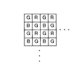
例えば、図4に示すようなRGBのカラーフィルタが市松状(水平方向および垂直方向に1画素おきにRGBが配置)に配置された単板カラーCCDを使用した場合には、各画素にはRGBのいずれか一色の信号成分しか存在しないため、欠落した色成分を補間する必要がある。
【0003】
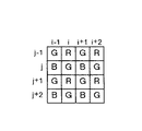
従来の補間方法は、欠落画素を単純に周囲の画素の平均を用いて補間するものである。具体的には、カラーCCDの各画素を図5に示すように、(j,i)とした場合には以下の(1)〜(4)に示すような演算で補間を行っていた。
【0004】
(1)G(i,j)の位置での補間
R=(R(i、j−1)+R(i,j+1))/2
G=G(i,j)
B=(B(i−1、j)+B(i+1、j))/2
【0005】
(2)B(i+1,j)の位置での補間
R=((R(i、j−1)+R(i,j+1)+R(i+2、j−1)+ R(i+2,j+1))/4
G=((G(i+1、j−1)+G(i,j)+G(i+2、j)+G(i+1,j+1))/4
B=B(i+1,j)
【0006】
(3)R(i,j+1)の位置での補間
R=R(i、j+1)
G=((G(i、j)+G(i−1,j+1)+G(i+1、j+1)+ G(i+1,j+2))/4
B=((B(i−1、j)+B(i+1,j)+B(i−1、j+2)+ B(i+1,j+2))/4
【0007】
(4)G(i+1,j+1)の位置での補間
R=(R(i、j+1)+R(i+2、j+1))/2
G=G(i+1、j+1)
B=((B(i+1,j)+B(i+1,j+2))/2
【0008】
しかるに、上記の如き欠落画素を単純に周囲の画素の平均を用いて補間する方法では、解像度が低下したり、画像内に密集線が存在する場合にはジッパーエッフェクトと呼ばれるギザギザ模様が生じ画質が劣化するという問題がある。特に、G信号は輝度成分に最も寄与するため、G信号の補間の良否が画質(特に解像度)を大きく左右することになる。
【0009】
上記問題を解決するための技術として、例えば、特開平5−75861号公報「画素補間装置」に開示されたものが知られている。
【0010】
かかる「画素補間装置」は、多数の画素を格子状に配列することで構成されるディジタル画像の欠落画素を補間する画素補間装置において、上記欠落画素の上下左右に位置する4個の周辺画素データの各々を所定の閾値を基準として2値化する2値化手段と、該2値化された周辺画素データの状況に基づき、該周辺画素データの全ての組み合わせから補間データの算出に用いる2個または4個の周辺画素データを選択する画素選択手段とを備え、上記画素選択手段により選択された周辺画素データの平均値を上記欠落画素の補間データとするものである。すなわち、2値化された周囲4個の画素データのパターンに基づき、2個または4個の画素データの平均を補間データとしている。
【0011】
【発明が解決しようとする課題】
しかしながら、上記特開平5−75861号公報の「画素補間装置」においては、信号レベルが低い部分ではノイズの影響も大きくなり周囲4画素を用いるだけでは正確な判定ができないという問題がある。また、2値化というプロセスも入るので、過って判定された場合には逆に画像劣化が従来の補間方式よりも大きくなるという問題がある。
【0012】
本発明は、上記課題に鑑みてなされたものであり、画像信号の補間が必要な場合に、高解像度でかつ輪郭の滑らかな画像を再現することが可能な画像処理装置および画像処理方法を提供することを目的とする。
【0013】
【課題を解決するための手段】
上記課題を解決するために、本発明は、水平方向および垂直方向に1画素おきに配列された画像信号の欠落した画素を補間する画像処理装置において、被補間画素の上下左右に位置する4個の近傍画素の画像信号の変化の度合および前記被補間画素の画像信号の変化の度合に基づいて、前記被補間画素の補間信号を生成する補間手段を備えたものである。
【0014】
また、本発明は、水平方向および垂直方向に1画素おきに配列された画像信号の欠落した画素を補間する画像処理装置において、被補間画素の画像信号の変化の度合、ならびに前記被補間画素の上下左右に位置する4個の近傍画素の水平方向および垂直方向の変化の度合の最小値に基づいて、前記被補間画素の補間信号を生成する補間手段を備えたものである。
【0015】
また、本発明は、前記補間手段は、前記被補間画素の上下左右に位置する4個の近傍画素の画像信号の変化の度合を当該各近傍画素を中心とした3×3画素の領域で判断し、前記被補間画素の画像信号の変化の度合を当該被補間画素を中心とした3×3画素の領域で判断するものである。
【0016】
また、本発明は、水平方向および垂直方向に1画素おきに配列された画像信号の欠落した画素を補間する画像処理装置において、被補間画素の左右に位置する2個の近傍画素の画像信号の変化の度合、前記被補間画素の画像信号の変化の度合、および前記被補間画素の水平方向に位置する近傍画素の画像信号と当該被補間画素の水平方向に位置する近傍画素の周囲の画素の画像信号との大小関係に基づいて、前記被補間画素の補間信号を生成する補間手段を備えたものである。
【0017】
また、本発明は、前記補間手段は、前記被補間画素の左右に位置する2個の近傍画素の水平方向の変化の度合の最小値または前記被補間画素の左右に位置する2個の近傍画素の垂直方向の変化の度合の最小値が、所定の閾値より大きい場合に当該各最小値に基づいて、前記被補間画素の補間信号を生成するものである。
【0018】
また、本発明は、前記補間手段は、前記被補間画素の左右に位置する2個の近傍画素の画像信号の変化の度合を当該各近傍画素を中心とした3×3画素の領域で判断し、前記被補間画素の画像信号の変化の度合を当該被補間画素を中心とした3×3画素の領域で判断するものである。
【0019】
また、本発明は、前記補間手段は、前記被補間画素の左右に位置する2個の近傍画素の水平方向の変化の度合の最小値または前記被補間画素の左右に位置する2個の近傍画素の垂直方向の変化の度合の最小値が所定の閾値以下の場合には、前記被補間画素の水平方向に位置する近傍画素の画像信号が当該被補間画素の水平方向に位置する近傍画素を中心とした3×3画素の領域で最大または最小であるか否かに応じて、前記被補間画素の補間信号を生成するものである。
【0020】
また、本発明は、前記補間手段は、前記被補間画素の上下左右に位置する4個の近傍画素を使用して前記被補間画素の補間信号を生成するものである。
【0021】
また、本発明は、前記補間手段は、前記被補間画素の上下左右に位置する4個の近傍画素のうち水平方向の画素と垂直方向の画素とを重み付け平均して前記被補間画素の補間信号を生成するものである。
【0022】
また、本発明は、水平方向および垂直方向に1画素おきに配列された画像信号の欠落した画素を補間する画像処理装置において、被補間画素の上下左右に位置する4個の近傍画素の画像信号の水平方向および垂直方向の変化の度合を演算する第1の演算手段と、前記記被補間画素の画像信号の水平方向および垂直方向の変化の度合を算出する第2の演算手段と、前記第1の演算手段により演算された前記被補間画素の上下左右に位置する4個の近傍画素の画像信号の水平方向の変化の度合の最小値を算出する第1の最小値算出手段と、前記第1の演算手段により演算された前記被補間画素の上下左右に位置する4個の近傍画素の画像信号の垂直方向の変化の度合の最小値を算出する第2の最小値算出手段と、前記第2の演算手段の算出結果、ならびに前記第1の最小値算出手段および前記第2の最小値算出手段により算出された最小値に基づき、前記被補間画素の上下左右に位置する4個の近傍画素のうち水平方向の画素と垂直方向の画素とを重み付け平均して前記被補間画素の補間信号を生成する補間信号演算手段とを備えたものである。
【0023】
また、本発明は、水平方向および垂直方向に1画素おきに配列された画像信号の欠落した画素を補間する画像処理装置において、被補間画素の左右に位置する2個の近傍画素の画像信号の水平方向および垂直方向の変化の度合を算出する第1の演算手段と、前記被補間画素の画像信号の水平方向および垂直方向の変化の度合を算出する第2の演算手段と、前記被補間画素の水平方向に位置する近傍画素の画像信号と当該被補間画素の水平方向に位置する近傍画素の周囲の画素の画像信号との大小関係を判別する大小関係判別手段と、前記第1の演算手段により演算された前記被補間画素の左右に位置する2個の近傍画素の画像信号の水平方向の変化の度合の最小値を算出する第1の最小値算出手段と、前記第1の演算手段により演算された前記被補間画素の左右に位置する2個の近傍画素の画像信号の垂直方向の変化の度合の最小値を算出する第2の最小値算出手段と、前記第1の最小値算出手段により算出された最小値と第1の閾値とを比較する第1の比較手段と、前記第2の最小値算出手段により算出された最小値と前記第1の閾値とを比較する第2の比較手段と、前記第2の演算手段により演算された前記被補間画素の画像信号の水平方向の変化の度合と第2の閾値とを比較する第3の比較手段と、前記第2の演算手段により演算された前記被補間画素の画像信号の垂直方向の変化の度合と前記第2の閾値とを比較する第4の比較手段と、前記第1〜第4の比較手段の比較結果および前記大小関係判別手段の判別結果に基づき、補間演算定数を選択する選択手段と、前記選択手段で選択された補間演算定数に基づき、前記被補間画素の上下左右に位置する4個の近傍画素のうち水平方向の画素と垂直方向の画素とを重み付け平均して前記被補間画素の補間信号を生成する補間信号演算手段とを備えたものである。
【0024】
【発明の実施の形態】
以下に添付図面を参照して、この発明に係る画像処理装置の好適な実施の形態を、[画像処理装置の構成]、[輝度信号用補間部の構成]の順に詳細に説明する。
【0025】
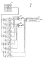
[画像処理装置の構成]
本実施の形態に係る画像処理装置を図1を参照して説明する。図1は、本実施の形態に係る画像処理装置のブロック図を示す。図1に示す画像処理装置は、撮像部101、色差信号用補間部102、輝度信号用補間部103、ホワイトバランス調整部104、γ補正部105、色差マトリクス部106,輝度マトリクス部107、アパーチャ補正部108、γ補正部109とから構成される。
【0026】
撮像部101は、上記図4に示すような原色フィルタ配列の単板カラーCCDからなり、被写体像を撮像し得られる画像信号をRGB信号に変換して色差信号用補間部102および輝度信号用補間部103に出力する。この場合、フィルタ色以外の信号は欠落している。
【0027】
色差信号用補間部102は、RGB信号の欠落している信号の補間を行って、補間したRGB信号をホワイトバランス調整部104に、RB信号を輝度マトリクス部107に出力する。具体的には、色差信号用補間部102は、RGB信号について、上記従来技術で示した補間方法、すなわち被補間画素(欠落画素)を単純に周囲の画素の平均を用いて補間する(図5参照)。ここで、色差信号の解像度は必ずしも必要ではなく、RGBの周波数特性が揃っていることが重要である。
【0028】
輝度信号用補間部103は、詳細には後述するが、輝度信号生成用のG信号の補間処理を行い、補間したG信号を輝度マトリクス部107に出力する。
【0029】
ホワイトバランス調整部104は、色差信号用補間部102から入力されるRGB信号に対してホワイトバランス調整を施した後、ホワイトバランス調整したRGB信号をγ補正部105に出力する。
【0030】
γ補正部105は、ホワイトバランス部104から入力されるRGB信号をγ変換した後、γ変換したRGB信号を色差マトリクス部106に出力する。
【0031】
色差マトリクス部106は、γ補正部105から入力されるRGB信号を、色差信号R−Y(Cr)、B−Y(Cb)に変換して出力する。
【0032】
輝度マトリクス部107は、色差信号用補間部102で補間されたRB信号と輝度信号用補間部103で補間されたG信号を使用して輝度信号Yを生成して、アパーチャ補正部108に出力する。なお、輝度信号Yを生成するに際して、G信号が最も輝度信号に寄与しRB信号は余り寄与しないため、従来の補間方法を用いて補間したRB信号を使用しても問題はない。
【0033】
アパーチャ補正部108は、輝度マトリクス部107から入力される輝度信号Yの高周波成分を強調して出力する。γ補正部109は、アパーチャ補正部108から入力される、高周波成分が強調された輝度信号Yをγ変換して出力する。
【0034】
[輝度信号用補間部の構成]
つぎに、上記輝度信号用補間部103の具体的な構成例について、(1)構成例1、(2)構成例2の順に詳細に説明する。
【0035】
(1)構成例1
図2は上記輝度信号用補間部103の構成例1を示すブロック図である。図2に示す輝度信号用補間部103は、演算部201〜208、最小値算出部211,212、演算部213を備える。同図において、被補間画素をx、G画素をa〜lとする。
【0036】
演算部201〜210は、被補間画素xの上下左右に位置する4個の近傍画素d,f,g,iの水平方向の変化の度合hu、hl、hr、hdおよび垂直方向の変化の度合vu、vl、vr、vdを下式(1)〜(8)によりそれぞれ演算し、水平方向の変化の度合hu、hl、hr、hdおよび垂直方向の変化の度合vu、vl、vr、vdをそれぞれ最小値算出部211,212に出力する。
【0037】
hu=|a+f−b−g| ・・・(1)
hl=|c+h−d−i| ・・・(2)
hr=|d+i−e−j| ・・・(3)
hd=|f+k−g−l| ・・・(4)
vu=|a+b−f−g| ・・・(5)
vl=|c+d−h−i| ・・・(6)
vr=|d+e−i−j| ・・・(7)
vd=|f+g−k−l| ・・・(8)
【0038】
演算部209,210は、被補間画素xにおける水平方向の変化の度合hx、垂直方向の変化の度合vxを下式(9)、(10)によりそれぞれ演算して、演算部213に出力する。
【0039】
hx=|f−g| ・・・(9)
vx=|d−i| ・・・(10)
【0040】
最小値算出部211、212は、被補間画素xの4つの近傍画素d,f,g,iの水平方向の変化の度合hu、hl、hr、hdの最小値HE、垂直方向の変化の度合vu,vl、vr、vdの最小値VEを下式(11)、(12)によりそれぞれ演算して、演算部213に出力する。
【0041】
HE=min(hu、hl、hr、hd) ・・・(11)
VE=min(vu,vl、vr、vd) ・・・(12)
【0042】
演算部213は、被補間画素xの水平方向の変化の度合hxおよび垂直方向の変化の度合vx、ならびに被補間画素xの4個の近傍画素d,f,g,iの水平方向の変化の度合hu、hl、hr、hdの最小値HEおよび垂直方向の変化の度合vu,vl、vr、vdの最小値VEに応じて、下式(13)に示すような演算式により、被補間画素xの4個の近傍画素d,f,g,iのうち垂直方向の画素(d+i)と水平方向の(f+g)とを重み付け平均して(混合比を変えて)、被補間画素xの補間信号を生成する。
【0043】
【数1】

これと同様の補間演算を他の欠落画素についても行って補間信号を輝度マトリクス部107に出力する。
【0045】
以上説明したように、構成例1の輝度信号用補間部によれば、被補間画素xの上下左右に位置する4個の近傍画素d,f,g,iの画像信号の変化の度合hu、hl、hr、hd、vu、vl、vr、vdおよび被補間画素xの画像信号の変化の度合hx、vxに基づいて、被補間画素xの補間信号を生成することとしたので、被補間画素の画素の変化の度合および被補間画素の近傍の画素の変化の度合に応じて画素補間の重みを連続的に変化させることができ、解像度が高くかつ輪郭が滑らかな画像の再現が可能となる。
【0046】
また、構成例1の輝度信号用補間部においては、被補間画素xの上下左右に位置する4個の近傍画素d,f,g,iの画像信号の水平方向の変化の度合hu、hl、hr、hdの最小値HE、被補間画素xの上下左右に位置する4個の近傍画素d,f,g,iの画像信号の垂直方向の変化の度合vu、vl、vr、vdの最小値VE、および被補間画素xの画像信号の変化の度合hx、vxに基づいて、被補間画素xの補間信号を生成することとしたので、より解像度が高くかつ輪郭が滑らかな画像の再現が可能となる。
【0047】
また、構成例1の輝度信号用補間部においては、被補間画素xの上下左右に位置する4個の近傍画素d,f,g,iの画像信号の変化の度合hu、hl、hr、hd、vu、vl、vr、vdを各近傍画素d,f,g,iを中心とした3×3画素の領域で判断し、被補間画素xの画像信号の変化の度合hx、vxを被補間画素xを中心とした3×3画素の領域で判断することとしたので、少ない演算量で各変化の度合を算出することが可能となる。
【0048】
また、構成例1の輝度信号用補間部においては、被補間画素xの上下左右に位置する4個の近傍画素d,f,g,iを使用して、被補間画素xの補間信号を生成することとしたので、少ない演算量で被補間画素xの補間信号を生成することが可能となる。
【0049】
また、構成例1の輝度信号用補間部においては、被補間画素xの上下左右に位置する4個の近傍画素d,f,g,iのうち水平方向の画素(f+g)と垂直方向の画素(d+i)とを上記式(13)の如く重み付け平均して、被補間画素xの補間信号を生成することとしたので、被補間画素xの補間信号を算出するに際して水平方向と垂直方向の近傍画素の混合比を最適にすることが可能となる。
【0050】
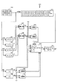
(2)構成例2
図3は上記輝度信号用補間部103の構成例2を示すブロック図である。図3に示す輝度信号用補間部103は、演算部301〜306、最小値算出部307、308、比較器309〜312、演算部313,セレクタ314、演算部315を備える。同図において、被補間画素をx、G画素をc〜jとする。
【0051】
演算部301〜304は、被補間画素xの左右に位置する(水平方向)2個の近傍画素f、gの水平方向の変化の度合hl、hrおよび垂直方向の変化の度合vl、vrをそれぞれ下式(14)〜(17)によりそれぞれ演算し、水平方向の変化の度合hl、hrおよび垂直方向の変化の度合vl、vrをそれぞれ最小値演算部307,308に出力する。
【0052】
hl=|c+h−d−i| ・・・(14)
hr=|d+i−e−j| ・・・(15)
vl=|c+d−h−i| ・・・(16)
vr=|d+e−i−j| ・・・(17)
【0053】
演算部305、306は、被補間画素xにおける水平方向および垂直方向の変化の度合hx、vxを下式(18)、(19)によりそれぞれ演算して、演算結果を比較器309,310、セレクタ314にそれぞれ出力する。
【0054】
hx=|f−g| ・・・(18)
vx=|d−f| ・・・(19)
【0055】
最小値演算部307、308は、被補間画素xの左右に位置する2個の近傍画素f、gの水平方向の変化の度合hl、hrの最小値HEおよび垂直方向の変化の度合vl、vrの最小値VEを、それぞれ下式(20)、(21)により演算し、演算結果を比較器311、312、セレクタ314にそれぞれ出力する。
【0056】
HE=min(hl、hr) ・・・(20)
VE=min(vl、vr) ・・・(21)
【0057】
比較器311は、入力される閾値C2と、被補間画素xの左右に位置する2個の近傍画素f、gの水平方向の変化の度合hl、hrの最小値HEとを比較し比較結果(HE>C2の場合「1」)をセレクタ314に出力する。比較器312は、入力される閾値C2と、被補間画素xの左右に位置する2個の近傍画素f、gの垂直方向の変化の度合vl、vrの最小値VEとを比較し比較結果(VE>C2の場合「1」)をセレクタ314に出力する。
【0058】
比較器309は、入力される閾値C1と、被補間画素xにおける水平方向の変化の度合hxとを比較し比較結果(hx>C1の場合「1」)をセレクタ314に出力する。比較器310は、入力される閾値C1と、被補間画素xにおける垂直方向の変化の度合vxとを比較し比較結果(vx>C1の場合「1」)をセレクタ314に出力する。
【0059】
また、演算部313は、補間画素xの水平方向の隣接画素fが、その周囲の画素c、d、h,iより大きい若しくは小さく、かつ、周囲の各画素c、d、h、iとの差の絶対値のいずれかが閾値C3よりも大きいかを、下式(22)により演算して演算結果をセレクタ314に出力する。
【0060】
(( f−c) >0 and (f−d) >0 and (f−h) >0 and (f−i) >0) or
(( f−c) <0 and (f−d) <0 and (f−h) <0 and (f−i<0)
and
(|f−c|>C3 or |f−d|>C3 or |f−h|>C3 or |f−i|>C3) ・・・(22)
【0061】
セレクタ314は、比較器309〜312と演算部313の出力結果に応じて、補間処理に使用する補間演算定数(S,T)を選択して、演算部315に出力する。
【0062】
具体的には、セレクタ314は、まず、比較器309〜312のいずれかの出力が「1」である場合、すなわち、下式(23)を満たす場合には、補間演算定数(S,T)として、(hx+HE、vx+VE)を演算部315に出力する。
【0063】
hx>C1 or vx>C1 or HE>C2 or VE>C2
・・・(23)
【0064】
また、セレクタ314は、上記式(23)を満たさない場合(「1」とならない場合)には、つぎに、演算部313の出力が「1」であるか判断し、「1」である場合、すなわち、上記式(22)を満たす場合には、補間演算定数(S,T)として、(1、3)を演算部315に出力する。
【0065】
また、セレクタ314は、比較器309〜312と演算部313の出力結果が「1」とならない場合、すなわち、上記式(22)、(23)のいずれも満たさない場合には、補間演算定数(S,T)として、(1、1)を演算部315に出力する。
【0066】
演算部315は、セレクタ314から入力される演算補間定数(S,T)に基づき、下式(24)の演算を行って被補間画素xの補間信号を算出する。
【0067】
【数2】
具体的には、演算部315は、セレクタ314から補間演算定数(S,T)として(hx+HE、vx+VE)が入力された場合、すなわち、上記(23)式を満たす場合には、下式(25)に示す演算を行って、被補間画素xの補間信号を算出する。この式(25)は、hx、vx、HE、VEに応じて、被補間画素xの垂直方向の画素(d+i)と垂直方向の画素(f+g)とを重み付け平均して(混合比を変えて)被補間画素xを補間するものである。
【0069】
【数3】
また、演算器315は、セレクタ314から被補間演算定数(S,T)として(1,3)が入力された場合、すなわち、上記式(23)を満たさないが、上記式(22)を満たす場合には、下式(26)に示す演算を行って被補間画素xの補間信号を算出する。この式(26)は、被補間画素xの垂直方向の画素(d+i)に比して、水平方向の画素(f+g)の重みを大きくして(混合比を大きくして)被補間画素xを補間するものである。
【0071】
【数4】
また、演算部315は、セレクタ314から補間演算定数(S,T)として(1,1)が入力された場合、すなわち、上記式(22)、(23)のいずれも満たさない場合には、下式(27)に示す演算を行って被補間画素xの補間信号を算出する。この式(27)は、被補間画素xの4個の近傍画素d、i、f、gを一対一の割合で被補間画素xを補間するものである。
【0073】
【数5】
以上説明したように、構成例2の輝度信号用補間部によれば、被補間画素xの左右に位置する2個の近傍画素f、gの画像信号の変化の度合hl、vl、hr、vr、被補間画素xの画像信号の変化の度合hx、vx、および被補間画素xの水平方向の近傍画素fの画像信号と当該近傍画素fの周囲の画素c,d,h,iの画像信号との大小関係に基づいて、被補間画素xの補間信号を生成することとしたので、解像度が高くかつ輪郭が滑らかな画像の再現が可能となる。また、構成例2においては、構成例1にと比べて垂直方向に3ラインしか使用していないため、構成例1と比較して2ラインのバッファが削減できる。そして、使用できる垂直方向の画像情報が少なくなるために生ずる水平線の解像度の低下を、上記式(22)に示す水平線を検出するための判別条件を導入して補っている。
【0075】
また、構成例2の輝度信号用補間部においては、被補間画素xの左右に位置する2個の近傍画素f、gの垂直方向の変化の度合vl、vrの最小値HEまたは当該近傍画素f、gの水平方向の変化の度合hl、hrの最小値VEが所定の閾値C2より大きい場合には、当該最小値HE、VEに基づいて、被補間画素の補間信号を生成することとしたので、より解像度が高くかつ輪郭が滑らかな画像の再現が可能となる。
【0076】
また、構成例2の輝度信号用補間部においては、被補間画素xの左右に位置する2個の近傍画素f、gの画像信号の変化の度合vl、vr、hl、hrを、各近傍画素f、gを中心とした3×3画素の領域で判断し、被補間画素xの画像信号の変化の度合を被補間画素xを中心とした3×3画素の領域で判断することとしたので、少ない演算量で各変化の度合を算出することが可能となる。
【0077】
また、構成例2の輝度信号用補間部においては、被補間画素xの左右に位置する2個の近傍画素f、gの垂直方向の変化の度合vl、vrの最小値VEおよび当該近傍画素f、gの水平方向の変化の度合hl、hrの最小値HEが所定の閾値C2以下の場合で、かつ、被補間画素xの画像信号の変化の度合hx、vxが所定の閾値C1以下である場合には、被補間画素xの水平方向の近傍画素fが画素fを中心とした3×3画素の領域(c,d,h,i)で、最大または最小であるか否かに応じて、被補間画素xの補間信号を生成することとしたので、より解像度が高くかつ輪郭が滑らかな画像の再現が可能となる。
【0078】
なお、本発明は、上記した実施の形態に限定されるものではなく、発明の要旨を変更しない範囲で適宜変更して実施可能である。
【0079】
また、本発明に係る画像処理装置は、デジタルスチルカメラ、デジタルビデオカメラ等に広く適用可能である。
【0080】
【発明の効果】
以上説明したように、本発明によれば、被補間画素の上下左右に位置する4個の近傍画素の画像信号の変化の度合および被補間画素の画像信号の変化の度合に基づいて、被補間画素の補間信号を生成することとしたので、被補間画素の画素の変化の度合および被補間画素の近傍の画素の変化の度合に応じて画素補間の重みを連続的に変化させることができ、解像度が高くかつ輪郭が滑らかな画像の再現が可能となる。
【0081】
また、本発明によれば、被補間画素の画像信号の変化の度合、ならびに被補間画素の上下左右に位置する4個の近傍画素の水平方向および垂直方向の変化の度合の最小値に基づいて、被補間画素の補間信号を生成することとしたので、より解像度が高くかつ輪郭が滑らかな画像の再現が可能となる。
【0082】
また、本発明によれば、被補間画素の上下左右に位置する4個の近傍画素の画像信号の変化の度合を当該各近傍画素を中心とした3×3画素の領域で判断し、被補間画素の画像信号の変化の度合を当該被補間画素を中心とした3×3画素の領域で判断することとしたので、少ない演算量で各変化の度合を算出することが可能となる。
【0083】
また、本発明によれば、被補間画素の左右に位置する2個の近傍画素の画像信号の変化の度合、被補間画素の画像信号の変化の度合、および被補間画素の水平方向に位置する近傍画素の画像信号と当該被補間画素の水平方向に位置する近傍画素の周囲の画素の画像信号との大小関係に基づいて、被補間画素の補間信号を生成することとしたので、小規模な低コストの回路構成で、解像度が高くかつ輪郭が滑らかな画像の再現が可能となる。
【0084】
また、本発明によれば、被補間画素の左右に位置する2個の近傍画素の水平方向の変化の度合の最小値または被補間画素の左右に位置する2個の近傍画素の垂直方向の変化の度合の最小値が、所定の閾値より大きい場合に当該各最小値に基づいて、被補間画素の補間信号を生成することとしたので、より解像度が高くかつ輪郭が滑らかな画像の再現が可能となる。
【0085】
また、本発明によれば、被補間画素の左右に位置する2個の近傍画素の画像信号の変化の度合を当該各近傍画素を中心とした3×3画素の領域で判断し、被補間画素の画像信号の変化の度合を当該被補間画素を中心とした3×3画素の領域で判断することとしたので、少ない演算量で各変化の度合を算出することが可能となる。
【0086】
また、本発明によれば、被補間画素の左右に位置する2個の近傍画素の水平方向の変化の度合の最小値または被補間画素の左右に位置する2個の近傍画素の垂直方向の変化の度合の最小値が所定の閾値以下の場合には、被補間画素の水平方向に位置する近傍画素の画像信号が当該被補間画素の水平方向に位置する近傍画素を中心とした3×3画素の領域で最大または最小であるか否かに応じて、被補間画素の補間信号を生成することとしたので、より解像度が高くかつ輪郭が滑らかな画像の再現が可能となる。
【0087】
また、本発明によれば、被補間画素の上下左右に位置する4個の近傍画素を使用して被補間画素の補間信号を生成することとしたので、少ない演算量で被補間画素の補間信号を生成することが可能となる。
【0088】
また、本発明によれば、被補間画素の上下左右に位置する4個の近傍画素のうち水平方向の画素と垂直方向の画素とを重み付け平均して被補間画素の補間信号を生成することとしたので、被補間画素の補間信号を算出するに際して水平方向と垂直方向の近傍画素の混合比を最適にすることが可能となる。
【0089】
また、本発明によれば、第1の演算手段は被補間画素の上下左右に位置する4個の近傍画素の画像信号の水平方向および垂直方向の変化の度合を演算し、第2の演算手段は被補間画素の画像信号の水平方向および垂直方向の変化の度合を算出し、第1の最小値算出手段は第1の演算手段により演算された被補間画素の上下左右に位置する4個の近傍画素の画像信号の水平方向の変化の度合の最小値を算出し、第2の最小値算出手段は第1の演算手段により演算された被補間画素の上下左右に位置する4個の近傍画素の画像信号の垂直方向の変化の度合の最小値を算出し、補間信号演算手段は第2の演算手段の算出結果、ならびに第1の最小値算出手段および第2の最小値算出手段により算出された最小値に基づき、被補間画素の上下左右に位置する4個の近傍画素のうち水平方向の画素と垂直方向の画素とを重み付け平均して被補間画素の補間信号を生成することとしたので、被補間画素の画素の変化の度合および被補間画素の近傍の画素の変化の度合に応じて画素補間の重みを連続的に変化させることができ、解像度が高くかつ輪郭が滑らかな画像の再現が可能となる。
【0090】
また、本発明によれば、第1の演算手段は被補間画素の左右に位置する2個の近傍画素の画像信号の水平方向および垂直方向の変化の度合を算出し、第2の演算手段は記被補間画素の画像信号の水平方向および垂直方向の変化の度合を算出し、大小関係判別手段は被補間画素の水平方向に位置する近傍画素の画像信号と当該被補間画素の水平方向に位置する近傍画素の周囲の画素の画像信号との大小関係を判別し、第1の最小値算出手段は第1の演算手段により演算された被補間画素の左右に位置する2個の近傍画素の画像信号の水平方向の変化の度合の最小値を算出し、第2の最小値算出手段は第1の演算手段により演算された被補間画素の左右に位置する2個の近傍画素の画像信号の垂直方向の変化の度合の最小値を算出し、第1の比較手段は第1の最小値算出手段により算出された最小値と第1の閾値とを比較し、第2の比較手段は第2の最小値算出手段により算出された最小値と第1の閾値とを比較し、第3の比較手段は第2の演算手段により演算された被補間画素の画像信号の水平方向の変化の度合と第2の閾値とを比較し、第4の比較手段は第2の演算手段により演算された被補間画素の画像信号の垂直方向の変化の度合と第2の閾値とを比較し、選択手段は第1〜第4の比較手段の比較結果および大小関係判別手段の判別結果に基づき、補間演算定数を選択し、補間信号演算手段は選択手段で選択された補間演算定数に基づき、被補間画素の上下左右に位置する4個の近傍画素のうち水平方向の画素と垂直方向の画素とを重み付け平均して被補間画素の補間信号を生成することとしたので、小規模な低コストの回路構成で、解像度が高くかつ輪郭が滑らかな画像の再現が可能となる。
【図面の簡単な説明】
【図1】 本実施の形態に係る画像処理装置の構成を示すブロック図である。
【図2】 図1の輝度信号用補間部の構成例1を示すブロック図である。
【図3】 図1の輝度信号用補間部の構成例2を示すブロック図である。
【図4】 RGBのカラーフィルタが市松状に配置された単板カラーCCDを示す図である。
【図5】 従来の補間方法を説明するための図である。
【符号の説明】
101 撮像部
102 色差信号用補間部
103 輝度信号用補間部
104 ホワイトバランス調整部
105 γ補正部
106 色差マトリクス部
107 輝度マトリクス部
108 アパーチャ補正部
109 γ補正部
201〜210 演算部
211、212 最小値算出部
213 演算部
301〜306 演算部
307,308 最小値算出部
309〜312 比較器
313 演算部
314 セレクタ
315 演算部[0001]
BACKGROUND OF THE INVENTION
The present invention relates to an image processing apparatus and an image processing method, and more particularly, to an image processing apparatus and an image processing method for performing interpolation of image signals of missing pixels.
[0002]
[Prior art]
For example, when a single-plate color CCD in which RGB color filters as shown in FIG. 4 are arranged in a checkered pattern (RGB is arranged every other pixel in the horizontal direction and the vertical direction) is used for each pixel. Since only one color signal component exists, it is necessary to interpolate the missing color component.
[0003]
The conventional interpolation method simply interpolates missing pixels using the average of surrounding pixels. Specifically, as shown in FIG. 5, when each pixel of the color CCD is (j, i), interpolation is performed by the calculations shown in the following (1) to (4).
[0004]
(1) Interpolation at the position of G (i, j)
R = (R (i, j-1) + R (i, j + 1)) / 2
G = G (i, j)
B = (B (i−1, j) + B (i + 1, j)) / 2
[0005]
(2) Interpolation at the position of B (i + 1, j)
R = ((R (i, j-1) + R (i, j + 1) + R (i + 2, j-1) + R (i + 2, j + 1)) / 4
G = ((G (i + 1, j-1) + G (i, j) + G (i + 2, j) + G (i + 1, j + 1)) / 4
B = B (i + 1, j)
[0006]
(3) Interpolation at the position of R (i, j + 1)
R = R (i, j + 1)
G = ((G (i, j) + G (i-1, j + 1) + G (i + 1, j + 1) + G (i + 1, j + 2)) / 4
B = ((B (i-1, j) + B (i + 1, j) + B (i-1, j + 2) + B (i + 1, j + 2)) / 4
[0007]
(4) Interpolation at the position of G (i + 1, j + 1)
R = (R (i, j + 1) + R (i + 2, j + 1)) / 2
G = G (i + 1, j + 1)
B = ((B (i + 1, j) + B (i + 1, j + 2)) / 2
[0008]
However, in the method of simply interpolating the missing pixels as described above using the average of the surrounding pixels, when the resolution is reduced or there are dense lines in the image, a jagged pattern called a zipper effect is generated and the image quality is increased. There is a problem of deterioration. In particular, since the G signal contributes most to the luminance component, the quality of interpolation of the G signal greatly affects the image quality (particularly the resolution).
[0009]
As a technique for solving the above problem, for example, one disclosed in Japanese Patent Laid-Open No. 5-75861 “Pixel Interpolator” is known.
[0010]
Such a “pixel interpolator” is a pixel interpolator that interpolates missing pixels in a digital image configured by arranging a large number of pixels in a grid pattern, and includes four pieces of peripheral pixel data positioned above, below, left and right of the missing pixels. And binarization means for binarizing each of them with a predetermined threshold as a reference, and two pieces used for calculating interpolation data from all combinations of the peripheral pixel data based on the status of the binarized peripheral pixel data Alternatively, a pixel selection unit that selects four pieces of peripheral pixel data is provided, and an average value of the peripheral pixel data selected by the pixel selection unit is used as interpolation data for the missing pixels. That is, based on the binarized pattern of the surrounding four pixel data, the average of the two or four pixel data is used as the interpolation data.
[0011]
[Problems to be solved by the invention]
However, the “pixel interpolation device” disclosed in Japanese Patent Application Laid-Open No. 5-75861 has a problem that the influence of noise becomes large at a portion where the signal level is low, and accurate determination cannot be made only by using four surrounding pixels. In addition, since a process of binarization is also included, there is a problem that if the determination is made excessively, the image deterioration becomes larger than that of the conventional interpolation method.
[0012]
The present invention has been made in view of the above problems, and provides an image processing apparatus and an image processing method capable of reproducing an image having a high resolution and a smooth outline when interpolation of an image signal is necessary. The purpose is to do.
[0013]
[Means for Solving the Problems]
In order to solve the above-described problem, the present invention provides an image processing apparatus that interpolates a pixel in which an image signal that is arranged every other pixel in the horizontal direction and the vertical direction is interpolated. Interpolating means for generating an interpolation signal for the interpolated pixel based on the degree of change in the image signal of the neighboring pixel and the degree of change in the image signal of the interpolated pixel.
[0014]
Further, the present invention provides an image processing apparatus that interpolates a pixel in which an image signal that is arranged every other pixel in the horizontal direction and the vertical direction is interpolated, the degree of change in the image signal of the interpolated pixel, and the interpolated pixel Interpolation means for generating an interpolated signal of the interpolated pixel based on the minimum value of the change in the horizontal direction and the vertical direction of four neighboring pixels located in the vertical and horizontal directions is provided.
[0015]
According to the present invention, the interpolation means determines the degree of change in the image signal of four neighboring pixels located above, below, left and right of the interpolated pixel in a 3 × 3 pixel area centered on each neighboring pixel. Then, the degree of change in the image signal of the interpolated pixel is determined in a 3 × 3 pixel area centered on the interpolated pixel.
[0016]
Further, the present invention provides an image processing apparatus for interpolating a pixel in which an image signal that is arranged every other pixel in the horizontal direction and the vertical direction is interpolated, and image signals of two neighboring pixels positioned on the left and right of the interpolated pixel. The degree of change, the degree of change in the image signal of the interpolated pixel, and the image signal of the neighboring pixel located in the horizontal direction of the interpolated pixel and the surrounding pixels of the neighboring pixel located in the horizontal direction of the interpolated pixel Interpolation means for generating an interpolation signal of the interpolated pixel based on the magnitude relationship with the image signal is provided.
[0017]
Further, according to the present invention, the interpolating means includes a minimum value of a horizontal change degree of two neighboring pixels located on the left and right of the interpolated pixel or two neighboring pixels located on the left and right of the interpolated pixel. When the minimum value of the degree of change in the vertical direction is larger than a predetermined threshold value, an interpolation signal of the interpolated pixel is generated based on each minimum value.
[0018]
According to the present invention, the interpolation means determines the degree of change in the image signal of two neighboring pixels located on the left and right of the interpolated pixel in a 3 × 3 pixel area centered on each neighboring pixel. The degree of change in the image signal of the interpolated pixel is determined in a 3 × 3 pixel area centered on the interpolated pixel.
[0019]
Further, according to the present invention, the interpolating means includes a minimum value of a horizontal change degree of two neighboring pixels located on the left and right of the interpolated pixel or two neighboring pixels located on the left and right of the interpolated pixel. When the minimum value of the degree of change in the vertical direction is less than or equal to a predetermined threshold value, the image signal of the neighboring pixel located in the horizontal direction of the interpolated pixel is centered on the neighboring pixel located in the horizontal direction of the interpolated pixel. The interpolation signal of the interpolated pixel is generated according to whether or not it is the maximum or minimum in the 3 × 3 pixel area.
[0020]
Further, according to the present invention, the interpolation means generates an interpolation signal of the interpolated pixel using four neighboring pixels located above, below, left and right of the interpolated pixel.
[0021]
Further, according to the present invention, the interpolation means weights and averages a horizontal pixel and a vertical pixel among four neighboring pixels located above, below, left and right of the interpolated pixel, and interpolates the interpolated pixel signal. Is generated.
[0022]
Further, the present invention provides an image processing apparatus for interpolating a pixel in which an image signal is arranged every other pixel in the horizontal direction and the vertical direction, and image signals of four neighboring pixels positioned above, below, left and right of the interpolated pixel. First calculating means for calculating the degree of change in the horizontal direction and vertical direction, second calculating means for calculating the degree of change in the horizontal direction and vertical direction of the image signal of the interpolated pixel, and the first First minimum value calculating means for calculating a minimum value of the degree of change in the horizontal direction of image signals of four neighboring pixels located above, below, left and right of the interpolated pixel calculated by one calculating means; Second minimum value calculating means for calculating the minimum value of the degree of change in the vertical direction of the image signal of four neighboring pixels located above, below, left and right of the interpolated pixel calculated by one calculating means; The calculation result of the calculation means of 2, Based on the minimum values calculated by the first minimum value calculation means and the second minimum value calculation means, and the horizontal pixels of the four neighboring pixels located above, below, left and right of the interpolated pixel, Interpolation signal calculation means for generating an interpolation signal of the interpolated pixel by weighted averaging of the pixels in the vertical direction is provided.
[0023]
Further, the present invention provides an image processing apparatus for interpolating a pixel in which an image signal that is arranged every other pixel in the horizontal direction and the vertical direction is interpolated, and image signals of two neighboring pixels positioned on the left and right of the interpolated pixel. First computing means for calculating the degree of change in the horizontal direction and vertical direction, second computing means for calculating the degree of change in the horizontal direction and vertical direction of the image signal of the interpolated pixel, and the interpolated pixel A magnitude relation discriminating means for discriminating a magnitude relation between an image signal of a neighboring pixel located in the horizontal direction of the pixel and an image signal of pixels around the neighboring pixel located in the horizontal direction of the interpolated pixel; and the first computing means A first minimum value calculating means for calculating a minimum value of the degree of change in the horizontal direction of the image signal of two neighboring pixels located on the left and right of the interpolated pixel calculated by the above, and the first calculating means Before being computed Calculated by a second minimum value calculating means for calculating the minimum value of the degree of change in the vertical direction of the image signal of two neighboring pixels located on the left and right of the interpolated pixel, and the first minimum value calculating means. A first comparison means for comparing a minimum value with a first threshold; a second comparison means for comparing the minimum value calculated by the second minimum value calculation means with the first threshold; Third comparison means for comparing the second threshold value with the degree of change in the horizontal direction of the image signal of the interpolated pixel calculated by the second calculation means, and the calculation performed by the second calculation means The fourth comparison means for comparing the degree of vertical change of the image signal of the interpolated pixel and the second threshold value, the comparison result of the first to fourth comparison means, and the magnitude relation discrimination means Selection means for selecting an interpolation operation constant based on the result, and the selection An interpolation signal of the interpolated pixel is obtained by weighted averaging the horizontal pixel and the vertical pixel among the four neighboring pixels located above, below, left, and right of the interpolated pixel based on the interpolation calculation constant selected in the stage. Interpolating signal calculation means for generating.
[0024]
DETAILED DESCRIPTION OF THE INVENTION
Exemplary embodiments of an image processing apparatus according to the present invention will be described in detail below in the order of [Configuration of image processing apparatus] and [Configuration of luminance signal interpolation unit].
[0025]
[Configuration of image processing apparatus]
An image processing apparatus according to the present embodiment will be described with reference to FIG. FIG. 1 is a block diagram of an image processing apparatus according to the present embodiment. The image processing apparatus shown in FIG. 1 includes an
[0026]
The
[0027]
The color difference
[0028]
As will be described in detail later, the luminance
[0029]
The white
[0030]
The
[0031]
The color
[0032]
The
[0033]
The
[0034]
[Configuration of Luminance Signal Interpolator]
Next, a specific configuration example of the luminance
[0035]
(1) Configuration example 1
FIG. 2 is a block diagram showing a configuration example 1 of the luminance
[0036]
The
[0037]
hu = | a + f−b−g | (1)
hl = | c + hd−i | (2)
hr = | d + i−e−j | (3)
hd = | f + k−g || (4)
vu = | a + bfg | (5)
vl = | c + d−h || (6)
vr = | d + e−j | (7)
vd = | f + g−kl | (8)
[0038]
The
[0039]
hx = | f−g | (9)
vx = | d−i | (10)
[0040]
The minimum
[0041]
HE = min (hu, hl, hr, hd) (11)
VE = min (vu, vl, vr, vd) (12)
[0042]
The
[0043]
[Expression 1]
The same interpolation calculation is performed for other missing pixels, and an interpolation signal is output to the
[0045]
As described above, according to the luminance signal interpolation unit of the configuration example 1, the degree hu of the change in the image signal of the four neighboring pixels d, f, g, i located above, below, left, and right of the interpolated pixel x. Since the interpolation signal of the interpolated pixel x is generated based on hl, hr, hd, vu, vl, vr, vd and the degree of change hx, vx of the image signal of the interpolated pixel x, the interpolated pixel The weight of pixel interpolation can be continuously changed according to the degree of change of the pixel and the degree of change of the pixel in the vicinity of the interpolated pixel, and an image with high resolution and smooth contour can be reproduced. .
[0046]
Further, in the luminance signal interpolation unit of the configuration example 1, the degree of change in the horizontal direction of the image signal of the four neighboring pixels d, f, g, i positioned above, below, left, and right of the interpolated pixel x, hu, hl, The minimum value HE of hr, hd, and the minimum values vu, vl, vr, vd of the vertical direction change of the image signals of four neighboring pixels d, f, g, i located above, below, left and right of the interpolated pixel x Since the interpolation signal for the interpolated pixel x is generated based on the degree VE and the degree of change in the image signal of the interpolated pixel x, hx and vx, it is possible to reproduce an image with higher resolution and smooth contours. It becomes.
[0047]
Further, in the luminance signal interpolation unit of the configuration example 1, the degree hu, hl, hr, hd of the change in the image signal of the four neighboring pixels d, f, g, i positioned above, below, left, and right of the interpolated pixel x. , Vu, vl, vr, vd are determined in a 3 × 3 pixel area centered on each neighboring pixel d, f, g, i, and the degree of change in the image signal of the interpolated pixel x is determined as hx, vx. Since the determination is made in a 3 × 3 pixel area centered on the pixel x, the degree of each change can be calculated with a small amount of calculation.
[0048]
Further, in the luminance signal interpolation unit of Configuration Example 1, an interpolation signal for the interpolated pixel x is generated using the four neighboring pixels d, f, g, and i positioned on the upper, lower, left, and right sides of the interpolated pixel x. Therefore, it is possible to generate an interpolation signal for the interpolated pixel x with a small amount of calculation.
[0049]
Further, in the luminance signal interpolation unit of the configuration example 1, the horizontal pixel (f + g) and the vertical pixel among the four neighboring pixels d, f, g, and i positioned above, below, left and right of the interpolated pixel x. Since (d + i) is weighted and averaged as in the above equation (13) to generate an interpolation signal for the interpolated pixel x, the vicinity of the horizontal direction and the vertical direction when calculating the interpolation signal for the interpolated pixel x It is possible to optimize the pixel mixture ratio.
[0050]
(2) Configuration example 2
FIG. 3 is a block diagram showing a configuration example 2 of the luminance
[0051]
The
[0052]
hl = | c + hd−i | (14)
hr = | d + i−e−j | (15)
vl = | c + d−h || (16)
vr = | d + e−j | (17)
[0053]
The
[0054]
hx = | f−g | (18)
vx = | d−f | (19)
[0055]
The minimum
[0056]
HE = min (hl, hr) (20)
VE = min (vl, vr) (21)
[0057]
The
[0058]
The
[0059]
In addition, the
[0060]
((fc)> 0 and (fd)> 0 and (fh)> 0 and (fi)> 0) or
((f−c) <0 and (f−d) <0 and (f−h) <0 and (f−i <0)
and
(| F-c |> C3 or | fd |> C3 or | fh |> C3 or | fi |> C3) (22)
[0061]
The
[0062]
Specifically, the
[0063]
hx> C1 or vx> C1 or HE> C2 or VE> C2
(23)
[0064]
Further, the
[0065]
In addition, the
[0066]
The
[0067]
[Expression 2]
Specifically, the
[0069]
[Equation 3]
Further, the
[0071]
[Expression 4]
In addition, when (1, 1) is input as the interpolation calculation constant (S, T) from the
[0073]
[Equation 5]
As described above, according to the luminance signal interpolation unit of the configuration example 2, the degree of change hl, vl, hr, vr of the image signals of the two neighboring pixels f, g located on the left and right of the interpolated pixel x. , The degree hx, vx of the change in the image signal of the interpolated pixel x, the image signal of the neighboring pixel f in the horizontal direction of the interpolated pixel x, and the image signal of the pixels c, d, h, i around the neighboring pixel f Since the interpolation signal of the interpolated pixel x is generated on the basis of the magnitude relationship with the above, it is possible to reproduce an image with a high resolution and a smooth contour. Further, in the configuration example 2, since only 3 lines are used in the vertical direction as compared with the configuration example 1, the buffer of 2 lines can be reduced compared to the configuration example 1. Then, a decrease in the resolution of the horizontal line caused by a decrease in usable vertical image information is compensated by introducing a discrimination condition for detecting the horizontal line shown in the above equation (22).
[0075]
In the luminance signal interpolation unit of the configuration example 2, the degree of change vl in the vertical direction of the two neighboring pixels f and g located on the left and right of the interpolated pixel x, the minimum value HE of vr, or the neighboring pixel f When the minimum values VE of the horizontal directions h and hr are larger than the predetermined threshold C2, the interpolation signal of the interpolated pixel is generated based on the minimum values HE and VE. Thus, it is possible to reproduce an image having a higher resolution and a smooth contour.
[0076]
Further, in the luminance signal interpolation unit of the configuration example 2, the degree of change vl, vr, hl, hr of the image signal of the two neighboring pixels f, g located on the left and right of the interpolated pixel x is set to each neighboring pixel. Since it is determined in the 3 × 3 pixel area centered on f and g, the degree of change in the image signal of the interpolated pixel x is determined in the 3 × 3 pixel area centered on the interpolated pixel x. It is possible to calculate the degree of each change with a small amount of calculation.
[0077]
Further, in the luminance signal interpolation unit of the configuration example 2, the two neighboring pixels f and g that are located on the left and right of the interpolated pixel x, the degree of vertical change vl, the minimum value VE of vr, and the neighboring pixel f , G in the horizontal direction of change hl, hr minimum value HE is less than or equal to a predetermined threshold C2, and the degree of change in image signal of the interpolated pixel x is less than or equal to a predetermined threshold C1. In this case, the neighboring pixel f in the horizontal direction of the interpolated pixel x is a 3 × 3 pixel region (c, d, h, i) centered on the pixel f, depending on whether it is maximum or minimum. Since the interpolation signal of the interpolated pixel x is generated, it is possible to reproduce an image with a higher resolution and a smooth contour.
[0078]
The present invention is not limited to the above-described embodiment, and can be implemented with appropriate modifications within a range that does not change the gist of the invention.
[0079]
The image processing apparatus according to the present invention can be widely applied to a digital still camera, a digital video camera, and the like.
[0080]
【The invention's effect】
As described above, according to the present invention, based on the degree of change of the image signal of the four neighboring pixels located above, below, left and right of the interpolated pixel and the degree of change of the image signal of the interpolated pixel, Since the interpolation signal of the pixel is generated, the weight of pixel interpolation can be continuously changed according to the degree of change of the pixel of the interpolated pixel and the degree of change of the pixel in the vicinity of the interpolated pixel, It is possible to reproduce an image having a high resolution and a smooth outline.
[0081]
Further, according to the present invention, based on the degree of change in the image signal of the interpolated pixel and the minimum value of the degree of change in the horizontal and vertical directions of four neighboring pixels located above, below, left and right of the interpolated pixel. Since the interpolation signal of the interpolated pixel is generated, it is possible to reproduce an image with a higher resolution and a smooth contour.
[0082]
In addition, according to the present invention, the degree of change in the image signal of four neighboring pixels located above, below, left, and right of the interpolated pixel is determined in a 3 × 3 pixel area centered on each neighboring pixel, Since the degree of change in the image signal of the pixel is determined in the 3 × 3 pixel area centered on the interpolated pixel, the degree of change can be calculated with a small amount of calculation.
[0083]
Further, according to the present invention, the degree of change of the image signal of the two neighboring pixels located on the left and right of the interpolated pixel, the degree of change of the image signal of the interpolated pixel, and the horizontal direction of the interpolated pixel are positioned. Since the interpolation signal of the interpolated pixel is generated based on the magnitude relationship between the image signal of the neighboring pixel and the image signal of the pixels around the neighboring pixel located in the horizontal direction of the interpolated pixel, An image with a high resolution and a smooth contour can be reproduced with a low-cost circuit configuration.
[0084]
Further, according to the present invention, the minimum value of the change in the horizontal direction of the two neighboring pixels located on the left and right of the interpolated pixel, or the vertical change of the two neighboring pixels located on the left and right of the interpolated pixel. When the minimum value of the degree is larger than a predetermined threshold, the interpolation signal of the interpolated pixel is generated based on each minimum value, so that it is possible to reproduce an image with higher resolution and smooth contour It becomes.
[0085]
Further, according to the present invention, the degree of change in the image signal of two neighboring pixels located on the left and right of the pixel to be interpolated is determined in a 3 × 3 pixel area centered on each neighboring pixel, and the pixel to be interpolated Therefore, it is possible to calculate the degree of each change with a small amount of calculation.
[0086]
Further, according to the present invention, the minimum value of the change in the horizontal direction of the two neighboring pixels located on the left and right of the interpolated pixel, or the vertical change of the two neighboring pixels located on the left and right of the interpolated pixel. If the minimum value of the degree is less than or equal to a predetermined threshold, the image signal of the neighboring pixel located in the horizontal direction of the interpolated pixel is 3 × 3 pixels centered on the neighboring pixel located in the horizontal direction of the interpolated pixel Since the interpolation signal of the interpolated pixel is generated depending on whether the area is the maximum or minimum in the area, it is possible to reproduce an image with higher resolution and smooth contour.
[0087]
In addition, according to the present invention, the interpolation signal of the interpolated pixel is generated using the four neighboring pixels located on the top, bottom, left, and right of the interpolated pixel. Can be generated.
[0088]
Further, according to the present invention, the interpolation signal of the interpolated pixel is generated by weighted averaging of the horizontal pixel and the vertical pixel among the four neighboring pixels located above, below, left and right of the interpolated pixel. Therefore, it is possible to optimize the mixing ratio of neighboring pixels in the horizontal direction and the vertical direction when calculating the interpolation signal of the interpolated pixel.
[0089]
Further, according to the present invention, the first calculating means calculates the degree of change in the horizontal direction and the vertical direction of the image signals of four neighboring pixels located above, below, left and right of the interpolated pixel, and the second calculating means Calculates the degree of change of the image signal of the interpolated pixel in the horizontal direction and the vertical direction, and the first minimum value calculating means includes four pieces positioned above, below, left and right of the interpolated pixel calculated by the first calculating means. The minimum value of the degree of change in the horizontal direction of the image signal of the neighboring pixel is calculated, and the second minimum value calculating means is the four neighboring pixels located above, below, left and right of the interpolated pixel calculated by the first calculating means. The minimum value of the degree of vertical change of the image signal is calculated, and the interpolation signal calculation means is calculated by the calculation result of the second calculation means, and the first minimum value calculation means and the second minimum value calculation means. Based on the minimum value Among the four neighboring pixels, the horizontal pixel and the vertical pixel are weighted and averaged to generate the interpolation signal of the interpolated pixel. The weight of pixel interpolation can be continuously changed in accordance with the degree of change of pixels in the vicinity of, so that an image having a high resolution and a smooth contour can be reproduced.
[0090]
According to the present invention, the first calculation means calculates the degree of change in the horizontal direction and the vertical direction of the image signal of two neighboring pixels located on the left and right of the interpolated pixel, and the second calculation means The degree of change in the horizontal and vertical directions of the image signal of the pixel to be interpolated is calculated, and the magnitude relation discriminating means positions the image signal of the neighboring pixel located in the horizontal direction of the interpolated pixel and the horizontal direction of the interpolated pixel. The first minimum value calculating means determines the magnitude relationship with the image signal of the surrounding pixels of the neighboring pixel to be processed, and the first minimum value calculating means is an image of two neighboring pixels located on the left and right of the interpolated pixel calculated by the first calculating means. The minimum value of the degree of change in the horizontal direction of the signal is calculated, and the second minimum value calculating means calculates the vertical values of the image signals of two neighboring pixels located on the left and right of the interpolated pixel calculated by the first calculating means. Calculate the minimum degree of change in direction and perform the first comparison The stage compares the minimum value calculated by the first minimum value calculating means with the first threshold value, and the second comparing means compares the minimum value calculated by the second minimum value calculating means and the first threshold value. The third comparing means compares the degree of change in the horizontal direction of the image signal of the interpolated pixel calculated by the second calculating means with the second threshold value, and the fourth comparing means is the second comparing means. The degree of change in the vertical direction of the image signal of the interpolated pixel calculated by the calculation means is compared with the second threshold value, and the selection means compares the comparison results of the first to fourth comparison means and the magnitude relation determination means. Based on the determination result, an interpolation calculation constant is selected, and the interpolation signal calculation means is based on the interpolation calculation constant selected by the selection means, and the horizontal pixel of the four neighboring pixels located above, below, left and right of the pixel to be interpolated. The interpolated signal of the interpolated pixel is generated by weighted averaging of the pixels in the vertical direction. Since it was decided to, in the circuit configuration of the small low-cost, high and contour resolution becomes possible to reproduce a smooth image.
[Brief description of the drawings]
FIG. 1 is a block diagram showing a configuration of an image processing apparatus according to an embodiment.
FIG. 2 is a block diagram showing a configuration example 1 of a luminance signal interpolation unit in FIG. 1;
3 is a block diagram showing a configuration example 2 of the luminance signal interpolation unit in FIG. 1; FIG.
FIG. 4 is a diagram showing a single-plate color CCD in which RGB color filters are arranged in a checkered pattern.
FIG. 5 is a diagram for explaining a conventional interpolation method.
[Explanation of symbols]
101 Imaging unit
102 Color difference signal interpolation unit
103 Luminance signal interpolation unit
104 White balance adjustment section
105 γ correction unit
106 Color difference matrix
107 Luminance matrix part
108 Aperture correction section
109 γ correction unit
201-210 arithmetic unit
211, 212 Minimum value calculator
213 Calculation unit
301 to 306 arithmetic unit
307, 308 Minimum value calculator
309-312 comparator
313 Calculation unit
314 Selector
315 Calculation unit
Claims (6)
被補間画素の上下左右に位置する4個の各近傍画素の画像信号の水平方向の変化の度合いのうちの最小値と、 The minimum value of the degree of change in the horizontal direction of the image signal of each of the four neighboring pixels located above, below, left and right of the interpolated pixel;
前記被補間画素の上下左右に位置する4個の各近傍画素の画像信号の垂直方向の変化の度合いのうちの最小値と、 A minimum value of the degree of change in the vertical direction of the image signal of each of the four neighboring pixels located above, below, left, and right of the interpolated pixel;
前記被補間画素の画像信号の水平方向および垂直方向の変化の度合いとに基づいて、 Based on the degree of change in the horizontal direction and vertical direction of the image signal of the interpolated pixel,
前記被補間画素の上下左右に位置する4個の近傍画素のうち、水平方向の画素の画像信号と垂直方向の画素の画像信号とを重み付け平均して前記被補間画素の補間信号を生成する前記被補間画素の補間信号を生成する補間手段を備えたことを特徴とする画像処理装置。 Of the four neighboring pixels located above, below, left, and right of the interpolated pixel, the horizontal pixel image signal and the vertical pixel image signal are weighted and averaged to generate the interpolated pixel interpolation signal. An image processing apparatus comprising interpolation means for generating an interpolation signal for a pixel to be interpolated.
被補間画素の左右に位置する2個の各近傍画素の画像信号の水平方向の変化の度合いのうちの最小値と、 The minimum value of the degree of change in the horizontal direction of the image signal of each of the two neighboring pixels located on the left and right of the interpolated pixel;
前記被補間画素の左右に位置する2個の近傍画素の画像信号の垂直方向の変化の度合いのうちの最小値と、 A minimum value of the degree of change in the vertical direction of the image signal of two neighboring pixels located on the left and right of the interpolated pixel;
前記被補間画素の画像信号の水平方向および垂直方向の変化の度合いと、 The degree of change in the horizontal and vertical directions of the image signal of the interpolated pixel;
前記被補間画素の水平方向に位置する近傍画素と当該被補間画素の水平方向に位置する近傍画素の周囲の画素との大小関係に基づいて、 Based on the size relationship between the neighboring pixels located in the horizontal direction of the interpolated pixel and the surrounding pixels of the neighboring pixels located in the horizontal direction of the interpolated pixel,
前記被補間画素の上下左右に位置する4個の近傍の画素のうち、水平方向の画素の画像信号と垂直方向の画素の画像信号とを重み付け平均して前記被補間画素の補間信号を生成する前記被補間画素の補間信号を生成する補間手段を備えたことを特徴とする画像処理装置。 Among four neighboring pixels located above, below, left, and right of the interpolated pixel, a horizontal pixel image signal and a vertical pixel image signal are weighted and averaged to generate an interpolated signal of the interpolated pixel. An image processing apparatus comprising interpolation means for generating an interpolation signal of the interpolated pixel.
被補間画素の上下左右に位置する4個の各近傍画素の画像信号の水平方向の変化の度合いのうちの最小値と、 The minimum value of the degree of change in the horizontal direction of the image signal of each of the four neighboring pixels located above, below, left and right of the interpolated pixel;
前記被補間画素の上下左右に位置する4個の近傍画素の画像信号の垂直方向の変化の度合いのうちの最小値と、 A minimum value of the degree of change in the vertical direction of the image signal of four neighboring pixels located above, below, left and right of the interpolated pixel;
前記被補間画素の画像信号の水平方向および垂直方向の変化の度合いとに基づいて、 Based on the degree of change in the horizontal direction and vertical direction of the image signal of the interpolated pixel,
前記被補間画素の上下左右に位置する4個の近傍の画素のうち、水平方向の画素の画像信号と垂直方向の画素の画像信号とを重み付け平均して前記被補間画素の補間信号を生成する前記被補間画素の補間信号を生成する補間工程を備えたことを特徴とする画像処理方法。 Among four neighboring pixels located above, below, left, and right of the interpolated pixel, a horizontal pixel image signal and a vertical pixel image signal are weighted and averaged to generate an interpolated signal of the interpolated pixel. An image processing method comprising an interpolation process for generating an interpolation signal of the interpolated pixel.
被補間画素の左右に位置する2個の各近傍画素の画像信号の水平方向の変化の度合いのうちの最小値と、 The minimum value of the degree of change in the horizontal direction of the image signal of each of the two neighboring pixels located on the left and right of the interpolated pixel;
前記被補間画素の左右に位置する2個の各近傍画素の画像信号の垂直方向の変化の度合いのうちの最小値と、 The minimum value of the degree of change in the vertical direction of the image signal of each of the two neighboring pixels located on the left and right of the interpolated pixel;
前記被補間画素の画像信号の水平方向および垂直方向の変化の度合いと、 The degree of change in the horizontal and vertical directions of the image signal of the interpolated pixel;
並びに前記被補間画素の水平方向に位置する近傍画素と当該被補間画素の水平方向に位置する近傍画素の周囲の画素との大小関係に基づいて、 In addition, based on the magnitude relationship between the neighboring pixels located in the horizontal direction of the interpolated pixel and the surrounding pixels of the neighboring pixels located in the horizontal direction of the interpolated pixel,
前記被補間画素の上下左右に位置する4個の画素のうち水平方向の画素と垂直方向の画素とを重み付け平均して前記被補間画素の補間信号を生成する前記被補間画素の補間信号を生成する補間工程を備えたことを特徴とする画像処理方法。 Generates an interpolated signal for the interpolated pixel by generating a weighted average of horizontal and vertical pixels among the four pixels located above, below, left, and right of the interpolated pixel. An image processing method comprising an interpolation step.
被補間画素の上下左右に位置する4個の近傍画素の画像信号の水平方向および垂直方向の変化の度合を演算する第1の演算手段と、
前記被補間画素の画像信号の水平方向および垂直方向の変化の度合を算出する第2の演算手段と、
前記第1の演算手段により演算された前記被補間画素の上下左右に位置する4個の近傍画素の画像信号の水平方向の変化の度合の最小値を算出する第1の最小値算出手段と、
前記第1の演算手段により演算された前記被補間画素の上下左右に位置する4個の近傍画素の画像信号の垂直方向の変化の度合の最小値を算出する第2の最小値算出手段と、
前記第2の演算手段の算出結果、ならびに前記第1の最小値算出手段および前記第2の最小値算出手段により算出された最小値に基づき、前記被補間画素の上下左右に位置する4個の近傍画素のうち水平方向の画素と垂直方向の画素とを重み付け平均して前記被補間画素の補間信号を生成する補間信号演算手段と、
を備えたことを特徴とする画像処理装置。In an image processing apparatus for interpolating missing pixels of an image signal arranged every other pixel in the horizontal direction and the vertical direction,
First computing means for computing the degree of change in the horizontal and vertical directions of the image signals of four neighboring pixels located above, below, left and right of the interpolated pixel;
Second calculating means for calculating the degree of horizontal and vertical change in the image signal of the object to be interpolated pixel,
First minimum value calculating means for calculating a minimum value of the degree of change in the horizontal direction of the image signal of four neighboring pixels located above, below, left and right of the interpolated pixel calculated by the first calculating means;
Second minimum value calculating means for calculating the minimum value of the degree of change in the vertical direction of the image signal of four neighboring pixels located above, below, left and right of the interpolated pixel calculated by the first calculating means;
Based on the calculation result of the second calculating means and the minimum values calculated by the first minimum value calculating means and the second minimum value calculating means, Interpolation signal calculation means for generating an interpolation signal of the interpolated pixel by weighted averaging of pixels in the horizontal direction and pixels in the vertical direction among neighboring pixels;
An image processing apparatus comprising:
した画素を補間する画像処理装置において、
被補間画素の左右に位置する2個の近傍画素の画像信号の水平方向および垂直方向の変
化の度合を算出する第1の演算手段と、
前記被補間画素の画像信号の水平方向および垂直方向の変化の度合を算出する第2の演算手段と、
前記被補間画素の水平方向に位置する近傍画素の画像信号と当該被補間画素の水平方向に位置する近傍画素の周囲の画素の画像信号との大小関係を判別する大小関係判別手段と、
前記第1の演算手段により演算された前記被補間画素の左右に位置する2個の近傍画素の画像信号の水平方向の変化の度合の最小値を算出する第1の最小値算出手段と、
前記第1の演算手段により演算された前記被補間画素の左右に位置する2個の近傍画素の画像信号の垂直方向の変化の度合の最小値を算出する第2の最小値算出手段と、
前記第1の最小値算出手段により算出された最小値と第1の閾値とを比較する第1の比較手段と、
前記第2の最小値算出手段により算出された最小値と前記第1の閾値とを比較する第2の比較手段と、
前記第2の演算手段により演算された前記被補間画素の画像信号の水平方向の変化の度合と第2の閾値とを比較する第3の比較手段と、
前記第2の演算手段により演算された前記被補間画素の画像信号の垂直方向の変化の度合と前記第2の閾値とを比較する第4の比較手段と、
前記第1〜第4の比較手段の比較結果および前記大小関係判別手段の判別結果に基づき、補間演算定数を選択する選択手段と、
前記選択手段で選択された補間演算定数に基づき、前記被補間画素の上下左右に位置する4個の近傍画素のうち水平方向の画素と垂直方向の画素とを重み付け平均して前記被補間画素の補間信号を生成する補間信号演算手段と、
を備えたことを特徴とする画像処理装置。In an image processing apparatus for interpolating missing pixels of an image signal arranged every other pixel in the horizontal direction and the vertical direction,
First calculation means for calculating the degree of change in the horizontal direction and vertical direction of the image signal of two neighboring pixels located on the left and right of the interpolated pixel;
Second computing means for calculating the degree of change in the horizontal and vertical directions of the image signal of the interpolated pixel;
A magnitude relation discriminating means for discriminating a magnitude relation between an image signal of a neighboring pixel located in the horizontal direction of the interpolated pixel and an image signal of a pixel around the neighboring pixel located in the horizontal direction of the interpolated pixel;
First minimum value calculating means for calculating a minimum value of the degree of change in the horizontal direction of image signals of two neighboring pixels located on the left and right of the interpolated pixel calculated by the first calculating means;
Second minimum value calculating means for calculating the minimum value of the degree of change in the vertical direction of the image signal of two neighboring pixels located on the left and right of the interpolated pixel calculated by the first calculating means;
First comparison means for comparing the minimum value calculated by the first minimum value calculation means with a first threshold;
Second comparing means for comparing the first threshold value with the minimum value calculated by the second minimum value calculating means;
Third comparison means for comparing the second threshold value with the degree of change in the horizontal direction of the image signal of the interpolated pixel calculated by the second calculation means;
Fourth comparison means for comparing the degree of change in the vertical direction of the image signal of the interpolated pixel calculated by the second calculation means with the second threshold;
Selection means for selecting an interpolation operation constant based on the comparison result of the first to fourth comparison means and the determination result of the magnitude relation determination means;
Based on the interpolation calculation constant selected by the selection means, a horizontal pixel and a vertical pixel are weighted and averaged among four neighboring pixels located above, below, left, and right of the pixel to be interpolated. Interpolation signal calculation means for generating an interpolation signal;
An image processing apparatus comprising:
Priority Applications (2)
| Application Number | Priority Date | Filing Date | Title |
|---|---|---|---|
| JP33279398A JP4097815B2 (en) | 1998-11-24 | 1998-11-24 | Image processing apparatus and image processing method |
| US09/441,051 US6744916B1 (en) | 1998-11-24 | 1999-11-16 | Image processing apparatus and method for interpolating missing pixels |
Applications Claiming Priority (1)
| Application Number | Priority Date | Filing Date | Title |
|---|---|---|---|
| JP33279398A JP4097815B2 (en) | 1998-11-24 | 1998-11-24 | Image processing apparatus and image processing method |
Publications (2)
| Publication Number | Publication Date |
|---|---|
| JP2000165893A JP2000165893A (en) | 2000-06-16 |
| JP4097815B2 true JP4097815B2 (en) | 2008-06-11 |
Family
ID=18258876
Family Applications (1)
| Application Number | Title | Priority Date | Filing Date |
|---|---|---|---|
| JP33279398A Expired - Fee Related JP4097815B2 (en) | 1998-11-24 | 1998-11-24 | Image processing apparatus and image processing method |
Country Status (2)
| Country | Link |
|---|---|
| US (1) | US6744916B1 (en) |
| JP (1) | JP4097815B2 (en) |
Families Citing this family (36)
| Publication number | Priority date | Publication date | Assignee | Title |
|---|---|---|---|---|
| JP4599672B2 (en) * | 1999-12-21 | 2010-12-15 | 株式会社ニコン | Interpolation processing apparatus and recording medium recording interpolation processing program |
| JP2002232908A (en) * | 2000-11-28 | 2002-08-16 | Monolith Co Ltd | Image interpolation method and device |
| US7515317B2 (en) * | 2001-12-10 | 2009-04-07 | Chen-Hsiang Shih | Compensating a zipper image by a K-value |
| US7012720B2 (en) * | 2002-01-14 | 2006-03-14 | Chen-Hsiang Shih | Method of effacing zipper image |
| JP4451044B2 (en) * | 2002-02-21 | 2010-04-14 | 株式会社メガチップス | Hybrid pixel interpolation device and hybrid pixel interpolation method |
| JP3984858B2 (en) * | 2002-05-01 | 2007-10-03 | キヤノン株式会社 | Image processing apparatus and control method thereof |
| US6933971B2 (en) * | 2002-05-14 | 2005-08-23 | Kwe International, Inc. | Reconstruction of color components in digital image processing |
| US7136541B2 (en) * | 2002-10-18 | 2006-11-14 | Sony Corporation | Method of performing sub-pixel based edge-directed image interpolation |
| TW589871B (en) * | 2002-11-19 | 2004-06-01 | Realtek Semiconductor Corp | Method for eliminating boundary image zippers |
| JP4302391B2 (en) * | 2002-11-28 | 2009-07-22 | 株式会社メガチップス | Pixel interpolation device, pixel interpolation method, and digital camera |
| JP2004229055A (en) * | 2003-01-24 | 2004-08-12 | Pentax Corp | Image processor |
| JP4322169B2 (en) * | 2003-07-16 | 2009-08-26 | 株式会社リコー | Document processing system, document processing method, document processing program |
| US7286721B2 (en) * | 2003-09-11 | 2007-10-23 | Leadtek Research Inc. | Fast edge-oriented image interpolation algorithm |
| JP3810404B2 (en) * | 2003-11-10 | 2006-08-16 | 三菱電機株式会社 | Pixel interpolation circuit and pixel interpolation method |
| TW200528770A (en) * | 2004-02-23 | 2005-09-01 | Altek Corp | Method and apparatus for determining edge inclination of an interested pixel in a color filter image array interpolation (CFAI) |
| JP4822773B2 (en) * | 2004-09-13 | 2011-11-24 | キヤノン株式会社 | Color noise reduction circuit and imaging apparatus using the same |
| US20060119724A1 (en) * | 2004-12-02 | 2006-06-08 | Fuji Photo Film Co., Ltd. | Imaging device, signal processing method on solid-state imaging element, digital camera and controlling method therefor and color image data generating method |
| US7570810B2 (en) * | 2005-02-24 | 2009-08-04 | Seiko Epson Corporation | Method and apparatus applying digital image filtering to color filter array data |
| JP4580791B2 (en) * | 2005-03-17 | 2010-11-17 | ユニデン株式会社 | Pixel interpolation method |
| GB2426881B (en) * | 2005-06-01 | 2010-12-29 | Snell & Wilcox Ltd | Method and apparatus for spatial interpolation of colour images |
| CN100546335C (en) * | 2005-12-21 | 2009-09-30 | 比亚迪股份有限公司 | A kind of color interpolation method of realizing abnormal point numerical value correction |
| TWI315504B (en) * | 2006-03-23 | 2009-10-01 | Nuvoton Technology Corp | Color interpolation method |
| US7755682B2 (en) * | 2006-03-29 | 2010-07-13 | Ite Tech. Inc. | Color interpolation method for Bayer filter array images |
| JP4735978B2 (en) * | 2006-07-21 | 2011-07-27 | ソニー株式会社 | Image processing apparatus, image processing method, and program |
| US8553758B2 (en) * | 2007-03-02 | 2013-10-08 | Sony Corporation | Motion parameter engine for true motion |
| US7889921B2 (en) * | 2007-05-23 | 2011-02-15 | Eastman Kodak Company | Noise reduced color image using panchromatic image |
| US8077234B2 (en) * | 2007-07-27 | 2011-12-13 | Kabushiki Kaisha Toshiba | Image pickup device and method for processing an interpolated color signal |
| US7825965B2 (en) * | 2007-09-07 | 2010-11-02 | Seiko Epson Corporation | Method and apparatus for interpolating missing colors in a color filter array |
| US20090092338A1 (en) * | 2007-10-05 | 2009-04-09 | Jeffrey Matthew Achong | Method And Apparatus For Determining The Direction of Color Dependency Interpolating In Order To Generate Missing Colors In A Color Filter Array |
| US8363728B2 (en) * | 2008-04-18 | 2013-01-29 | Sony Corporation | Block based codec friendly edge detection and transform selection |
| US8139883B2 (en) * | 2008-07-29 | 2012-03-20 | Sony Corporation | System and method for image and video encoding artifacts reduction and quality improvement |
| US20100067818A1 (en) * | 2008-09-15 | 2010-03-18 | Sony Corporation, A Japanese Corporation | System and method for high quality image and video upscaling |
| US8463035B2 (en) * | 2009-05-28 | 2013-06-11 | Gentex Corporation | Digital image processing for calculating a missing color value |
| JP4585602B1 (en) * | 2009-09-18 | 2010-11-24 | 株式会社東芝 | Image processing apparatus, display apparatus, and image processing method |
| US9769430B1 (en) | 2011-06-23 | 2017-09-19 | Gentex Corporation | Imager system with median filter and method thereof |
| EP2815393B1 (en) | 2012-02-14 | 2023-04-05 | Gentex Corporation | High dynamic range imager system |
Family Cites Families (4)
| Publication number | Priority date | Publication date | Assignee | Title |
|---|---|---|---|---|
| JP2667938B2 (en) | 1991-09-13 | 1997-10-27 | 三菱電機株式会社 | Pixel interpolation device |
| US5506619A (en) * | 1995-03-17 | 1996-04-09 | Eastman Kodak Company | Adaptive color plan interpolation in single sensor color electronic camera |
| JP3503372B2 (en) * | 1996-11-26 | 2004-03-02 | ミノルタ株式会社 | Pixel interpolation device and pixel interpolation method |
| JPH11122626A (en) * | 1997-10-17 | 1999-04-30 | Nikon Corp | Image processing method, system and record medium recording image processing program |
-
1998
- 1998-11-24 JP JP33279398A patent/JP4097815B2/en not_active Expired - Fee Related
-
1999
- 1999-11-16 US US09/441,051 patent/US6744916B1/en not_active Expired - Fee Related
Also Published As
| Publication number | Publication date |
|---|---|
| JP2000165893A (en) | 2000-06-16 |
| US6744916B1 (en) | 2004-06-01 |
Similar Documents
| Publication | Publication Date | Title |
|---|---|---|
| JP4097815B2 (en) | Image processing apparatus and image processing method | |
| JP4380805B2 (en) | Color sample interpolation method, apparatus and camera | |
| JP4066484B2 (en) | Image processing apparatus, image processing method, and camera | |
| US7577315B2 (en) | Method and apparatus for processing image data of a color filter array | |
| US7812868B2 (en) | Signal processing method and apparatus, and image sensing apparatus | |
| KR100667803B1 (en) | Method and apparatus for reducing color artifact and noise cosidering color channel correlation | |
| JP4668185B2 (en) | Image processing method | |
| JP3771054B2 (en) | Image processing apparatus and image processing method | |
| WO2005112470A1 (en) | Image processing device and image processing program | |
| JP4011861B2 (en) | Signal processing apparatus and method | |
| JP2004048465A (en) | Apparatus and program for image processing | |
| JP3540758B2 (en) | Horizontal contour signal generation circuit for single-chip color camera | |
| US7489822B2 (en) | Image processing apparatus and method for detecting a direction of an edge in the vicinity of a pixel of interest and generating all color signals for each pixel by interpolation using color signals of a pixel of interest and its neighbor pixels, and a recording medium having a program recorded thereon for causing the apparatus to perform the method | |
| US9401006B2 (en) | Image processing apparatus, image processing method, and storage medium | |
| JP3663777B2 (en) | Color signal interpolation method | |
| JP4380399B2 (en) | Imaging apparatus, noise reduction apparatus, noise reduction method, and program | |
| JP2009206552A (en) | Image processing apparatus | |
| JP3662949B2 (en) | Signal interpolation method | |
| KR101327790B1 (en) | Image interpolation method and apparatus | |
| JP4122082B2 (en) | Signal processing apparatus and processing method thereof | |
| JP2000165892A (en) | Pixel interpolation method and image processor | |
| JP5109911B2 (en) | Imaging apparatus and interpolation processing method | |
| JP4269367B2 (en) | Camera signal processing apparatus and camera signal processing method | |
| JP2014200033A (en) | Image processing device, method, and program | |
| JP3926019B2 (en) | Imaging device |
Legal Events
| Date | Code | Title | Description |
|---|---|---|---|
| A977 | Report on retrieval |
Free format text: JAPANESE INTERMEDIATE CODE: A971007 Effective date: 20050523 |
|
| A131 | Notification of reasons for refusal |
Free format text: JAPANESE INTERMEDIATE CODE: A131 Effective date: 20051004 |
|
| A521 | Request for written amendment filed |
Free format text: JAPANESE INTERMEDIATE CODE: A523 Effective date: 20051205 |
|
| A131 | Notification of reasons for refusal |
Free format text: JAPANESE INTERMEDIATE CODE: A131 Effective date: 20061212 |
|
| A521 | Request for written amendment filed |
Free format text: JAPANESE INTERMEDIATE CODE: A523 Effective date: 20070209 |
|
| TRDD | Decision of grant or rejection written | ||
| A01 | Written decision to grant a patent or to grant a registration (utility model) |
Free format text: JAPANESE INTERMEDIATE CODE: A01 Effective date: 20080311 |
|
| A61 | First payment of annual fees (during grant procedure) |
Free format text: JAPANESE INTERMEDIATE CODE: A61 Effective date: 20080312 |
|
| R150 | Certificate of patent or registration of utility model |
Free format text: JAPANESE INTERMEDIATE CODE: R150 |
|
| FPAY | Renewal fee payment (event date is renewal date of database) |
Free format text: PAYMENT UNTIL: 20110321 Year of fee payment: 3 |
|
| FPAY | Renewal fee payment (event date is renewal date of database) |
Free format text: PAYMENT UNTIL: 20120321 Year of fee payment: 4 |
|
| FPAY | Renewal fee payment (event date is renewal date of database) |
Free format text: PAYMENT UNTIL: 20130321 Year of fee payment: 5 |
|
| FPAY | Renewal fee payment (event date is renewal date of database) |
Free format text: PAYMENT UNTIL: 20140321 Year of fee payment: 6 |
|
| LAPS | Cancellation because of no payment of annual fees |