JP4097092B2 - Exhaust gas treatment device and its operation method - Google Patents
Exhaust gas treatment device and its operation method Download PDFInfo
- Publication number
- JP4097092B2 JP4097092B2 JP2005504753A JP2005504753A JP4097092B2 JP 4097092 B2 JP4097092 B2 JP 4097092B2 JP 2005504753 A JP2005504753 A JP 2005504753A JP 2005504753 A JP2005504753 A JP 2005504753A JP 4097092 B2 JP4097092 B2 JP 4097092B2
- Authority
- JP
- Japan
- Prior art keywords
- exhaust gas
- gas
- duct
- mist eliminator
- heat
- Prior art date
- Legal status (The legal status is an assumption and is not a legal conclusion. Google has not performed a legal analysis and makes no representation as to the accuracy of the status listed.)
- Expired - Fee Related
Links
Images


Classifications
-
- F—MECHANICAL ENGINEERING; LIGHTING; HEATING; WEAPONS; BLASTING
- F23—COMBUSTION APPARATUS; COMBUSTION PROCESSES
- F23J—REMOVAL OR TREATMENT OF COMBUSTION PRODUCTS OR COMBUSTION RESIDUES; FLUES
- F23J15/00—Arrangements of devices for treating smoke or fumes
- F23J15/06—Arrangements of devices for treating smoke or fumes of coolers
-
- F—MECHANICAL ENGINEERING; LIGHTING; HEATING; WEAPONS; BLASTING
- F23—COMBUSTION APPARATUS; COMBUSTION PROCESSES
- F23J—REMOVAL OR TREATMENT OF COMBUSTION PRODUCTS OR COMBUSTION RESIDUES; FLUES
- F23J13/00—Fittings for chimneys or flues
- F23J13/02—Linings; Jackets; Casings
-
- F—MECHANICAL ENGINEERING; LIGHTING; HEATING; WEAPONS; BLASTING
- F23—COMBUSTION APPARATUS; COMBUSTION PROCESSES
- F23J—REMOVAL OR TREATMENT OF COMBUSTION PRODUCTS OR COMBUSTION RESIDUES; FLUES
- F23J15/00—Arrangements of devices for treating smoke or fumes
-
- F—MECHANICAL ENGINEERING; LIGHTING; HEATING; WEAPONS; BLASTING
- F23—COMBUSTION APPARATUS; COMBUSTION PROCESSES
- F23J—REMOVAL OR TREATMENT OF COMBUSTION PRODUCTS OR COMBUSTION RESIDUES; FLUES
- F23J15/00—Arrangements of devices for treating smoke or fumes
- F23J15/02—Arrangements of devices for treating smoke or fumes of purifiers, e.g. for removing noxious material
-
- F—MECHANICAL ENGINEERING; LIGHTING; HEATING; WEAPONS; BLASTING
- F23—COMBUSTION APPARATUS; COMBUSTION PROCESSES
- F23J—REMOVAL OR TREATMENT OF COMBUSTION PRODUCTS OR COMBUSTION RESIDUES; FLUES
- F23J15/00—Arrangements of devices for treating smoke or fumes
- F23J15/08—Arrangements of devices for treating smoke or fumes of heaters
-
- Y—GENERAL TAGGING OF NEW TECHNOLOGICAL DEVELOPMENTS; GENERAL TAGGING OF CROSS-SECTIONAL TECHNOLOGIES SPANNING OVER SEVERAL SECTIONS OF THE IPC; TECHNICAL SUBJECTS COVERED BY FORMER USPC CROSS-REFERENCE ART COLLECTIONS [XRACs] AND DIGESTS
- Y02—TECHNOLOGIES OR APPLICATIONS FOR MITIGATION OR ADAPTATION AGAINST CLIMATE CHANGE
- Y02E—REDUCTION OF GREENHOUSE GAS [GHG] EMISSIONS, RELATED TO ENERGY GENERATION, TRANSMISSION OR DISTRIBUTION
- Y02E20/00—Combustion technologies with mitigation potential
- Y02E20/30—Technologies for a more efficient combustion or heat usage
Description
本発明はボイラ等の燃焼排ガスの脱硫装置を含む排ガス処理装置とその運用方法に係り、特に脱硫装置の運転停止時にノンリーク式ガス・ガスヒータ(以下、GGHと称することがある。)再加熱器側、あるいはスチーム・ガスヒータ(以下、SGHと称することがある。)とGGH再加熱器側とから放出される熱を逃がすのに好適な熱抑制装置を配置した排ガス処理装置とその運用方法に関する。 The present invention relates to an exhaust gas treatment device including a combustion exhaust gas desulfurization device such as a boiler, and an operation method thereof, and particularly to a non-leak type gas / gas heater (hereinafter sometimes referred to as GGH) reheater side when the desulfurization device is stopped. Alternatively, the present invention relates to an exhaust gas treatment apparatus provided with a heat suppression device suitable for releasing heat released from a steam gas heater (hereinafter sometimes referred to as SGH) and the GGH reheater side, and an operation method thereof.
大気汚染防止のため、排ガス中の硫黄酸化物の除去装置として、湿式石灰石−石膏法脱硫装置が広く実用化されている。この脱硫装置を含む排ガス処理装置の主要機器である従来技術(特開平6−238127号公報など)の系統図を図6に示す。 In order to prevent air pollution, a wet limestone-gypsum desulfurization apparatus has been widely put to practical use as a sulfur oxide removal apparatus in exhaust gas. FIG. 6 shows a system diagram of a conventional technique (Japanese Patent Laid-Open No. 6-238127) that is a main device of an exhaust gas treatment apparatus including this desulfurization apparatus.
火力発電所等から発生した硫黄酸化物および煤塵を含む未処理排ガスg1はボイラダクト1より入口ダンパ3のある脱硫装置入口ダクト2を通り、脱硫ファン4で昇圧され、GGH熱回収器5を通り脱硫装置の吸収塔6に導かれる。未処理排ガスg1は吸収塔6内で噴霧吸収液と対向流あるいは平行流で気液接触することで排ガス中の硫黄酸化物は吸収液滴表面を介して吸収除去され、煤塵は液滴との衝突により物理的に除去される。なお、ボイラダクト1には入口ダクト2と出口ダクト7を直接通るダクト部分を設け、その部分にはバイパスダンパ17、17を配置しておき、吸収塔6を迂回して未処理排ガスg1を煙突13に直接流す場合にはバイパスダンパ17、17を開にする。
Untreated exhaust gas g1 containing sulfur oxides and dust generated from a thermal power plant or the like passes through a
排ガス流れに同伴する微小な液滴は脱硫装置出口ダクト7を通り、吸収塔6の出口に設置されたミストエリミネータ8で除去され、浄化された処理排ガスg2は煙突13から大気中に排出される。このとき、排煙の大気拡散性の向上と白煙防止を図るため及び出口ダクト7や煙突13の内面の低温腐食防止を図るためにGGH再加熱器9で昇温され、その後に煙突13から排出される。
なおノンリーク式GGH熱回収器5とノンリーク式GGH再加熱器9の間は熱媒体配管21と該配管21の開閉弁22と熱媒体供給用ポンプ23が設けられている。
Fine droplets accompanying the exhaust gas flow pass through the
Between the non-leak GGH
従来技術では、脱硫装置の運転が停止し、入口ダクト2の入口ダンパ3及び出口ダクト7の出口ダンパ10が閉まったとき、GGH再加熱器9から放出される熱は逃げ場がないため、出口ダクト7の内部の雰囲気温度が約90〜150℃まで上昇し、GGH再加熱器9の前流側にあるミストエリミネータ8の樹脂製エレメントが高熱により変形したり、出口ダクト7内面の防食ライニングに熱劣化が生じる不具合があった。
In the prior art, when the operation of the desulfurization apparatus is stopped and the
上記従来技術では、脱硫装置の運転停止時のGGH再加熱器9から放出される約90〜150℃の高温の残熱の逃げ場について配慮がなされておらず、出口ダクト7にあるミストエリミネータ8の樹脂製エレメントが高熱により変形したり、出口ダクト7内面の防食ライニングに熱劣化が生じる等の問題があった。
In the above prior art, no consideration is given to the escape place of the high-temperature residual heat of about 90 to 150 ° C. discharged from the GGH reheater 9 when the desulfurization apparatus is stopped, and the
本発明の課題は、脱硫装置の運転停止時にGGH再加熱器9から放出される約90〜150℃の高温の熱を効率的に外部に排出させ、機器や防食ライニング材の損傷を防ぎ、長期間安定した排ガス処理装置の運用を図ることにある。 The object of the present invention is to efficiently discharge high-temperature heat of about 90 to 150 ° C. released from the GGH reheater 9 when the desulfurization apparatus is shut down to prevent damage to equipment and anticorrosion lining material. The purpose is to operate an exhaust gas treatment apparatus that is stable for a period of time.
本発明の上記課題は次の構成により解決される。
請求項1記載の発明は、火炉から排出する排ガスのダクトに排ガスの流れ方向上流側から順に、少なくともノンリーク式ガス・ガスヒータ熱回収器、吸収塔、ミストエリミネータ及び前記熱回収器との間で熱媒体を循環させるノンリーク式ガス・ガスヒータ再加熱器を配置した排ガス処理装置において、ミストエリミネータとノンリーク式ガス・ガスヒータ再加熱器の間の排ガスダクトに、ノンリーク式ガス・ガスヒータ再加熱器からの放散熱を抑制する熱抑制装置を配置し、該熱抑制装置として、
(a) ミストエリミネータとノンリーク式ガス・ガスヒータ再加熱器の間の排ガスダクトに放風装置を備えた構成、及び
(b)ミストエリミネータを構成するエレメント、吸収塔出口ダクト、吸収塔とミストエリミネータの間の排ガスダクト及び/又はミストエリミネータとノンリーク式ガス・ガスヒータ再加熱器の間の排ガスダクトに、吸収塔の運転停止時のノンリーク式ガス・ガスヒータ再加熱器からの放散熱に耐える耐熱樹脂材料及び/又は防食ライニング材を施した構成
からなる(a)と(b)のうちの一以上の構成を設けた排ガス処理装置である。
The above-described problems of the present invention are solved by the following configuration.
According to the first aspect of the present invention, heat is generated between at least a non-leak type gas / gas heater heat recovery unit, an absorption tower, a mist eliminator, and the heat recovery unit in order from the upstream side in the exhaust gas flow direction to the exhaust gas duct discharged from the furnace. In an exhaust gas treatment system with a non-leak gas / gas heater reheater that circulates the medium, the heat dissipated from the non-leak gas / gas heater reheater is placed in the exhaust gas duct between the mist eliminator and the non-leak gas / gas heater reheater. place suppressing heat suppression device, as heat suppression device,
(A) a configuration in which an exhaust gas duct between a mist eliminator and a non-leak gas / gas heater reheater is provided with a ventilator; and
(B) Operation of the absorption tower on the elements constituting the mist eliminator, the absorption tower outlet duct, the exhaust gas duct between the absorption tower and the mist eliminator and / or the exhaust gas duct between the mist eliminator and the non-leak type gas / gas heater reheater Configuration with heat-resistant resin material and / or anti-corrosion lining material that can withstand the heat dissipated from the non-leak gas / gas heater reheater when stopped
An exhaust gas treatment device provided with one or more of the configurations of (a) and (b) .
上記構成により、吸収塔6の運転停止時にノンリーク式ガス・ガスヒータ再加熱器9からの放散熱があっても熱抑制(放熱)装置により放散熱を外部に排出させることにより、排ガス処理装置を構成する非金属材料製の機器に損傷を与えることがない。
そして、上記構成により、前記(a)の場合には、排ガスダクト内の熱を放風弁11と放風配管12などから放熱させる。
(b)ミストエリミネータ8を構成するエレメント、吸収塔出口ダクト、吸収塔6とミストエリミネータ8の間の排ガスダクト及び/又はミストエリミネータ8とノンリーク式ガス・ガスヒータ再加熱器9の間の排ガスダクト(スチーム・ガスヒータ16を備えた構成である場合には、ミストエリミネータ8とスチーム・ガスヒータ16の間の排ガスダクト及び/又はスチーム・ガスヒータ16とノンリーク式ガス・ガスヒータ再加熱器9の間の排ガスダクト)に、吸収塔6の運転停止時のノンリーク式ガス・ガスヒータ再加熱器9からの放散熱(スチーム・ガスヒータ16を備えている場合にはスチーム・ガスヒータ16からの放散熱を含む)に耐える耐熱樹脂材料及び/又は防食ライニング材を施す。
従って、排ガス処理装置を構成する非金属材料製の機器に損傷を与えることがない。
With the above configuration, even if there is heat dissipated from the non-leak type gas / gas heater reheater 9 when the
And by the said structure, in the case of said (a), the heat | fever in an exhaust gas duct is thermally radiated from the ventilation valve 11 and the ventilation pipe 12 grade | etc.,.
(B) Elements constituting the
Therefore, the non-metallic material equipment constituting the exhaust gas treatment apparatus is not damaged.
上記本発明の排ガス処理装置では、ミストエリミネータ8とノンリーク式ガス・ガスヒータ熱再加熱器9の間の排ガスダクトにスチーム・ガスヒータ16を備え、かつ上記ミストエリミネータ8とスチーム・ガスヒータ16の間の排ガスダクトに、スチーム・ガスヒータ16からの放散熱を抑制する熱抑制装置を備えた構成とすることができる。
In the exhaust gas treatment apparatus of the present invention, a steam gas heater 16 is provided in the exhaust gas duct between the
前記スチーム・ガスヒータ16を備えた上記本発明の排ガス処理装置でも同様に、吸収塔6の運転停止時のスチーム・ガスヒータ16及びノンリーク式ガス・ガスヒータ再加熱器9からの放散熱があっても防食ライニング材の耐熱温度以下で、前記放散熱を外部に排出させることにより、排ガス処理装置を構成する非金属材料製の機器に損傷を与えることがない。
Similarly, the exhaust gas treatment apparatus of the present invention provided with the steam gas heater 16 is also anticorrosive even if there is heat dissipated from the steam gas heater 16 and the non-leak type gas / gas heater reheater 9 when the
更に放散熱を抑制する熱抑制装置として、
(c)ミストエリミネータとノンリーク式ガス・ガスヒータ再加熱器の間の排ガスダクトに、排ガスダクト内部の雰囲気温度を測定する温度計を設置し、該温度計が設定温度以上であると作動するミストエリミネータを構成するエレメント及び/又は排ガスダクト内部壁面及びその周辺を洗浄液で洗浄するスプレノズル配管と該配管の開閉弁をミストエリミネータの前面側及び後面側のうち、少なくとも前面側に配置した構成を設けても良い。
前記(c)の場合には、前記温度計18の測定温度が設定温度以上になると、スプレノズル配管19からミストエリミネータ8のエレメント及び/又は排ガスダクト内部壁面及びその周辺を洗浄する洗浄液を噴霧させる。
従って、排ガス処理装置を構成する非金属材料製の機器に損傷を与えることがない。 Furthermore, as a heat suppression device that suppresses dissipated heat,
(C) A mist eliminator that is installed in the exhaust gas duct between the mist eliminator and the non-leak type gas / gas heater reheater and that measures the ambient temperature inside the exhaust gas duct, and that operates when the thermometer is above the set temperature. There may be provided a configuration in which a spray nozzle pipe for cleaning the inner wall of the exhaust gas duct and the exhaust gas duct and its periphery with a cleaning liquid and an opening / closing valve for the pipe are arranged at least on the front side and the rear side of the mist eliminator. good.
In the case of (c) , when the temperature measured by the
Therefore, the non-metallic material equipment constituting the exhaust gas treatment apparatus is not damaged.
請求項4記載の発明における吸収塔6は、
(a)吸収液を貯留する循環タンクと、
(b)該循環タンクの上側にボイラなどの燃焼装置から排出される排ガスをほぼ水平方向に導入する入口ダクト2と排ガスをほぼ水平方向に排出させる出口ダクト7を設け、前記入口ダクト2と出口ダクト7の間に排ガス流路を設け、その排ガス流路を入口ダクト側と出口ダクト側の二室に分割するために天井部側に開口部を有する鉛直方向に立てた仕切板20を設け、該仕切板20で入口ダクト2から導入される排ガスが上向きに流れる上昇流領域と天井側の開口部で反転した後に出口ダクト7に向けて下向きに排ガスが流れる下降流領域を形成し、噴出する吸収液スラリが排ガスと上昇流領域では向流接触し、下降流領域では並流接触するように前記各領域に吸収液スラリを噴霧するスプレノズル23を
設けた二室式吸収塔で構成しても良い。
上記二室式吸収塔の構成を用いると、比較的少ないスペースで排煙脱硫処理が行える利点がある。
The
(A) a circulation tank for storing the absorption liquid;
(B) An
Using the configuration of the two-chamber type absorption tower has an advantage that the flue gas desulfurization treatment can be performed in a relatively small space.
また、請求項5記載の発明は、請求項1記載の排ガス処理装置の運用方法であって、熱抑制装置を、吸収塔の運転停止時に発生するノンリーク式ガス・ガスヒータ再加熱器9からの放散熱を抑制するように作動させる排ガス処理装置の運用方法である。
The invention according to
請求項6記載の発明は、請求項3記載の排ガス処理装置の運用方法であって、吸収塔6の運転停止時にミストエリミネータ8とノンリーク式ガス・ガスヒータ再加熱器9の間及び/又はミストエリミネータ8とスチーム・ガスヒータ16の間の排ガスダクトの雰囲気温度を測定する温度計18の計測値が設定値以上になると、スプレノズル配管19の開閉弁が作動し、スプレノズル配管19から洗浄液をミストエリミネータ8のエレメント及びその周辺に噴霧する方法を採用することができる。
The invention according to
以下に本発明の実施例について図面を用いて説明する。
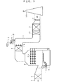
図1は本実施例の熱抑制装置を備えた排ガス処理装置の主要機器の系統図を示し、図2は図1に示した系統図を配置図の形で示したものである。
排ガス処理装置全体の系統の構成については図6で説明したシステムと同様の構成であり、火力発電所等から発生した硫黄酸化物および煤塵を含む未処理排ガスg1がボイラダクト1より入口ダンパ3のある入口ダクト2を通り脱硫ファン4で昇圧されてノンリーク式GGH熱回収器5を経由して脱硫装置の吸収塔6に導かれる。未処理排ガスg1中の硫黄酸化物は脱硫装置の吸収塔6内で噴霧吸収液により吸収除去され、煤塵は液滴との衝突により物理的に除去される。排ガス流れに同伴する微小な液滴は出口ダクト7のミストエリミネータ8で除去され、浄化された処理排ガスg2はノンリーク式GGH再加熱器9で昇温され、その後に煙突13から排出される。
なおノンリーク式GGH熱回収器5とノンリーク式GGH再加熱器9の間は熱媒体配管21と該配管21の開閉弁22と熱媒体供給用ポンプ23が設けられている。
Embodiments of the present invention will be described below with reference to the drawings.
FIG. 1 shows a system diagram of main equipment of an exhaust gas treatment apparatus provided with a heat suppression apparatus of the present embodiment, and FIG. 2 shows the system diagram shown in FIG. 1 in the form of a layout diagram.
The system configuration of the entire exhaust gas treatment apparatus is the same as the system described in FIG. 6, and an untreated exhaust gas g1 containing sulfur oxides and soot generated from a thermal power plant or the like has an
Between the non-leak GGH
図1及び図2に示す実施例は、GGH再加熱器9とその前流側の出口ダクト7に設けられたミストエリミネータ8との間に放風弁11及び放風配管12から構成される放風装置(熱抑制装置の一例)を設置したことに特徴がある。
In the embodiment shown in FIGS. 1 and 2, a discharge valve 11 and a discharge pipe 12 are provided between a GGH reheater 9 and a
吸収塔6の運転停止(脱硫ファン4の停止で入口ダンパ3と出口ダンパ10も閉止される。)と同時に放風弁11を全閉から全開にし、GGH再加熱器9の熱媒体の残熱により温度上昇しようとする処理排ガスg2を周囲に設置してあるミストエリミネータ8のエレメント等の樹脂製内部部品や防食ライニング材の耐熱温度以下で外部に排出させるシステム運用にしている。前述の放風装置の設置により吸収塔6の運転停止時にミストエリミネータ8のエレメント等の樹脂製内部部品や防食ライニング材に熱変形や熱劣化等の損傷を与えることがない。従って、長期間、性能的にも構造的にも安定した脱硫装置の運用を図ることができる。
Simultaneously with the operation stop of the absorption tower 6 (when the
ここでは、放風装置の構成として、放風弁11と放風配管12の組み合わせで、運用の方法として、吸収塔6の運転停止と同時に放風弁11を全閉から全開にする方法を説明したが、本発明は放風弁11の型式や放風配管12のサイズ、形状を限定するものではない。また、排ガス処理装置の系内で使用する非金属材料の耐熱温度以下に保持できる容量の放風配管12のサイズや設置員数、そして放風弁11の開閉時間を考慮した型式を選定すれば良い。また、周囲雰囲気温度により放風弁11の開度を変えても良い。
Here, as a configuration of the air discharge device, a method of operating the air discharge valve 11 from fully closed to fully open simultaneously with the operation stop of the
また、従来方式の排ガス処理装置では放風装置がないため、良質な石こうを得るための酸化用攪拌機14に供給する酸化用空気15も吸収塔6の運転停止中には系内から外部に放出する新たな逃がしラインを設ける必要があった。しかし、上記実施例では、放風弁11と放風配管12の組み合わせからなる放風装置を利用して吸収塔6の運転停止中も系内から酸化用空気15を外部に排出できるので、必要に応じて酸化用空気15を吸収塔6の運転停止中にも吸収液中に供給し続けることができる。
In addition, since the conventional exhaust gas treatment apparatus does not have a ventilator, the oxidant air 15 supplied to the
また、図2に示した放風弁11と放風配管12から構成される放風装置を設置すると共に、吸収塔6の出口部のミストエリミネータ8とGGH再加熱器9の間の出口ダクト7の内部雰囲気温度を測定する温度計18を設置し、図2に示すようにミストエリミネータ8の後面及び/又は前面に、ミストエリミネータエレメントを洗浄液で洗浄するスプレノズル配管19を取り付けておく。この洗浄液の噴霧で排ガスダクト内部壁面及びその周辺を洗浄することもできる。
Further, the outlet between the blow-off valve 11 and the blow-off co When installing composed blow-off device from the pipe 12, absorption
そして、温度計18が設定温度を示すとスプレノズル配管19から洗浄液の噴霧を開始することで、非金属のミストエリミネータエレメントや出口ダクト7の内部壁面及びその周辺の防食ライニング材を保護することができる。
Then, when the
本発明の排ガス処理装置の他の実施例を図3〜図5に示す。
図3に示す縦型スプレ式吸収塔6を備えた脱硫装置は図2に示す脱硫装置と同じであるが、ノンリーク式GGH熱回収器5やノンリーク式GGH再加熱器9の伝熱面積を少なくするために、GGH再加熱器9の前流側にSGH(スチームガスヒータ)16を追設した構成からなる実施例を示す。
図4には脱硫装置の吸収塔6として、塔内の空塔部を二分する仕切板20を有するリターンフロー型スプレ式(二室式)吸収塔を備えた系統において、GGH再加熱器9とミストエリミネータ8との間の出口ダクト7に放風弁11及び放風配管12から構成される放風装置を設置した実施例を示す。
図5に示す実施例も図4と同じく、リターンフロー型スプレ式吸収塔6を用いる系統であるが、ノンリーク式GGH熱回収器5やノンリーク式GGH再加熱器9の伝熱面積を少なくなくするために、GGH再加熱器9の前流側の出口ダクト7にSGH16を追設した構成である。
Another embodiment of the exhaust gas treatment apparatus of the present invention is shown in FIGS.
The desulfurization apparatus provided with the vertical spray
FIG. 4 shows a system equipped with a return flow type spray type (two-chamber type) absorption tower having a partition plate 20 that bisects an empty part in the tower as an
The embodiment shown in FIG. 5 is also a system using the return flow type spray
上記、図3〜図5に示す排ガス処理装置のいずれの場合もノンリーク式GGH再加熱器9とミストエリミネータ8との間あるいはSGH16とミストエリミネータ8との間の出口ダクト7に放風弁11及び放風配管12から構成される放風装置を設置することにより、図1及び図2で説明した系統と同様な効果が得られる。
In any of the above-described exhaust gas treatment apparatuses shown in FIGS. 3 to 5, the discharge valve 11 and the
同様に他の実施例として、図3〜図5に示す放風弁11と放風配管12から構成される放風装置を設置すると共に、吸収塔6出口のミストエリミネータ8とGGH再加熱器側9、あるいはミストエリミネータ8とSGH16の間の出口ダクト7に、該出口ダクト内部の雰囲気温度を測定する温度計18を設置し、ミストエリミネータ8の後面及び/又は前面に、ミストエリミネータエレメントを洗浄液で洗浄するスプレノズル配管19及び該配管19の開閉弁(図示せず)を取り付け、設定温度になるとスプレノズル配管19から洗浄液を噴霧する構成にしても、図1と図2の排ガス処理装置で説明した効果と同様な効果が得られる。
なお、本発明の実施例では吸収塔6の構成は、いかなる型式のものでもよく、その型式に特に限定はない。またノンリーク式であればGGH再加熱器9の構成に特に限定はなく、いかなる型式のものでも使用できる。
As another example in the same manner, FIGS while installing composed blow-off device from a blow-off valve 11 and the blow-off pipe 12 shown in 5, the
In the embodiment of the present invention, the structure of the
本発明の排ガス処理装置のもう一つの実施例として、(a)放風装置(放風弁11や放風配管12)及び(c)温度計18とミストエリミネータ洗浄スプレノズル配管19を設置せず、(b)ミストエリミネータ8を構成するエレメント、吸収塔出口ダクト、吸収塔6とミストエリミネータ8の間の排ガスダクト及び/又はミストエリミネータ8とノンリーク式ガス・ガスヒータ再加熱器9の間の排ガスダクト(スチーム・ガスヒータ16を備えた構成である場合には、ミストエリミネータ8とスチーム・ガスヒータ16の間の排ガスダクト及び/又はスチーム・ガスヒータ16とノンリーク式ガス・ガスヒータ再加熱器9の間の排ガスダクト)に、吸収塔6の運転停止時のノンリーク式ガス・ガスヒータ再加熱器9からの放散熱(スチーム・ガスヒータ16を備えている場合にはスチーム・ガスヒータ16からの放散熱を含む)に耐える耐熱樹脂材料及び/又は防食ライニング材を施す構成にすれば、図1及び図2で説明した構成の効果と同様な効果が得られる。上記(b)の耐熱樹脂材料としては例えばポリプロピレン材料などを用い、防食ライニング材としては例えばガラスフレーク材料などを用いる。
As another embodiment of the exhaust gas treatment apparatus of the present invention, (a) a ventilator (a vent valve 11 or a vent pipe 12) and ( c ) a
さらに、上記(a)放風装置(放風弁11や放風配管12)を用いる構成、(b)ミストエリミネータ8を構成するエレメント、吸収塔出口ダクト、吸収塔6とミストエリミネータ8の間の排ガスダクト及び/又はミストエリミネータ8とノンリーク式ガス・ガスヒータ再加熱器9の間の排ガスダクト(スチーム・ガスヒータ16を備えた構成である場合には、ミストエリミネータ8とスチーム・ガスヒータ16の間の排ガスダクト及び/又はスチーム・ガスヒータ16とノンリーク式ガス・ガスヒータ再加熱器9の間の排ガスダクト)に、吸収塔6の運転停止時のノンリーク式ガス・ガスヒータ再加熱器9からの放散熱(スチーム・ガスヒータ16を備えている場合にはスチーム・ガスヒータ16からの放散熱を含む)に耐える耐熱樹脂材料及び/又は防食ライニング材を施す構成、及び(c)温度計18とミストエリミネータ洗浄スプレノズル配管19と該配管の開閉弁(図示せず)を用いる構成からなる(a)〜(c)の構成の内少なくとも二以上を組み合わせて使用すれば、図1及び図2で説明した実施例の効果と同様な効果が得られる。
Further, (a) a configuration using the ventilating device (the vent valve 11 and the discharge pipe 12), (b) an element constituting the
本発明によれば、放散熱を抑制する熱抑制装置により、(1)吸収塔を備えた脱硫装置の運転停止時にGGH再加熱器又はSGHとGGH再加熱器から放出される約90〜150℃の高温の熱を効率的に外部に排出させ、あるいは排ガスダクトに設置される機器の非金属材料を洗浄液で冷却し、また排ガスダクトの内部壁面および排ガスダクトに設置される機器の内部部品や防食ライニング材の損傷を防ぎ、長期間安定した脱硫装置の運用を図ることができる。
(2) また、吸収塔の運転停止中の酸化用空気供給に対しても、上記熱抑制装置が有効に利用できるので、経済的な付帯効果がある。
According to the present invention, the heat suppression device that suppresses the dissipated heat causes (1) about 90 to 150 ° C. released from the GGH reheater or the SGH and GGH reheater when the desulfurization device including the absorption tower is stopped. The high-temperature heat is efficiently discharged to the outside, or the nonmetallic material of the equipment installed in the exhaust gas duct is cooled with the cleaning liquid, and the internal wall of the exhaust gas duct and the internal parts of the equipment installed in the exhaust gas duct and anticorrosion It is possible to prevent damage to the lining material and to operate a desulfurization apparatus that is stable for a long time.
(2) Moreover, since the said heat suppression apparatus can be utilized effectively also with respect to the supply of oxidation air while the operation of the absorption tower is stopped, there is an economical incidental effect.
図1は、本発明の実施例の排ガス処理装置の主要構成の系統を示す図である。
図2は、本発明の実施例の排ガス処理装置の主要構成の配置を示す図である。
図3は、本発明の他の実施例の排ガス処理装置の主要構成の配置を示す図である。
図4は、本発明の他の実施例の排ガス処理装置の主要構成の配置を示す図である。
図5は、本発明の他の実施例の排ガス処理装置の主要構成の配置を示す図である。
図6は、従来技術の排ガス処理装置の主要構成の系統を示す図である。
FIG. 1 is a diagram showing a system of a main configuration of an exhaust gas treatment apparatus according to an embodiment of the present invention.
FIG. 2 is a diagram showing an arrangement of main components of the exhaust gas treatment apparatus according to the embodiment of the present invention.
FIG. 3 is a diagram showing an arrangement of main components of an exhaust gas treatment apparatus according to another embodiment of the present invention.
FIG. 4 is a diagram showing an arrangement of main components of an exhaust gas treatment apparatus according to another embodiment of the present invention.
FIG. 5 is a diagram showing an arrangement of main components of an exhaust gas treatment apparatus according to another embodiment of the present invention.
FIG. 6 is a diagram showing a system of a main configuration of a conventional exhaust gas treatment apparatus.
Claims (6)
ミストエリミネータとノンリーク式ガス・ガスヒータ再加熱器の間の排ガスダクトに、ノンリーク式ガス・ガスヒータ再加熱器からの放散熱を抑制する熱抑制装置を配置し、
該熱抑制装置として、
(a) ミストエリミネータとノンリーク式ガス・ガスヒータ再加熱器の間の排ガスダクトに放風装置を備えた構成、及び
(b)ミストエリミネータを構成するエレメント、吸収塔出口ダクト、吸収塔とミストエリミネータの間の排ガスダクト及び/又はミストエリミネータとノンリーク式ガス・ガスヒータ再加熱器の間の排ガスダクトに、吸収塔の運転停止時のノンリーク式ガス・ガスヒータ再加熱器からの放散熱に耐える耐熱樹脂材料及び/又は防食ライニング材を施した構成
からなる(a)と(b)のうちの一以上の構成を設けたことを特徴とする排ガス処理装置。A non-leak gas that circulates the heat medium at least between the non-leak gas / gas heater heat recovery device, the absorption tower, the mist eliminator, and the heat recovery device in order from the upstream side in the exhaust gas flow direction to the exhaust gas duct discharged from the furnace. In the exhaust gas treatment device with a gas heater reheater,
In the exhaust gas duct between the mist eliminator and the non-leak type gas / gas heater reheater, a heat suppression device is arranged to suppress the heat dissipated from the non-leak type gas / gas heater reheater,
As the heat suppression device,
(A) A configuration in which an exhaust gas duct between the mist eliminator and a non-leak gas / gas heater reheater is provided with a ventilator; and
(B) Operation of the absorption tower in the elements constituting the mist eliminator, the absorption tower outlet duct, the exhaust gas duct between the absorption tower and the mist eliminator and / or the exhaust gas duct between the mist eliminator and the non-leak type gas / gas heater reheater Configuration with heat-resistant resin material and / or anti-corrosion lining material that can withstand the heat dissipated from the non-leak gas / gas heater reheater when stopped
An exhaust gas treatment apparatus provided with one or more of the configurations of (a) and (b) .
(c)ミストエリミネータとノンリーク式ガス・ガスヒータ再加熱器の間の排ガスダクトに、排ガスダクト内部の雰囲気温度を測定する温度計を設置し、該温度計が設定温度以上であると作動するミストエリミネータを構成するエレメント及び/又は排ガスダクト内部壁面及びその周辺を洗浄液で洗浄するスプレノズル配管と該配管の開閉弁をミストエリミネータの前面側及び後面側のうち、少なくとも前面側に配置した構成
を設けたことを特徴とする請求項1又は2記載の排ガス処理装置。 Furthermore, as a heat suppression device that suppresses dissipated heat,
(C) A mist eliminator that is installed in the exhaust gas duct between the mist eliminator and the non-leak type gas / gas heater reheater and that measures the ambient temperature inside the exhaust gas duct, and that operates when the thermometer is above the set temperature. of front and rear side of the mist eliminator off valve of the spray nozzle pipes and piping of the elements and / or exhaust gas duct inner wall and the periphery thereof constituting washed with washing solution, configuration arranged at least on the front side
The exhaust gas treatment apparatus according to claim 1 or 2, wherein the provided.
(a)吸収液を貯留する循環タンクと、
(b)該循環タンクの上側にボイラなどの燃焼装置から排出される排ガスをほぼ水平方向に導入する入口ダクトと排ガスをほぼ水平方向に排出させる出口ダクトを設け、前記入口ダクトと出口ダクトの間に排ガス流路を設け、その排ガス流路を入口ダクト側と出口ダクト側の二室に分割するために天井部側に開口部を有する鉛直方向に立てた仕切板を設け、該仕切板で入口ダクトから導入される排ガスが上向きに流れる上昇流領域と天井側の開口部で反転した後に出口ダクトに向けて下向きに排ガスが流れる下降流領域を形成し、噴出する吸収液スラリが排ガスと上昇流領域では向流接触し、下降流領域では並流接触するように前記各領域にスプレノズルを
設けた二室式吸収塔であることを特徴とする請求項1記載の排ガス処理装置。The absorption tower
(A) a circulation tank for storing the absorption liquid;
(B) An inlet duct for introducing exhaust gas discharged from a combustion device such as a boiler in a substantially horizontal direction and an outlet duct for discharging exhaust gas in a substantially horizontal direction are provided on the upper side of the circulation tank, and between the inlet duct and the outlet duct. In order to divide the exhaust gas flow path into two chambers on the inlet duct side and the outlet duct side, a vertical partition plate having an opening on the ceiling portion side is provided, and the partition plate is used to enter the exhaust gas flow path. An upward flow region where the exhaust gas introduced from the duct flows upward and a downward flow region where the exhaust gas flows downward toward the outlet duct after reversing at the ceiling side opening are formed, and the absorbing liquid slurry that is ejected is the upward flow of the exhaust gas 2. The exhaust gas treatment apparatus according to claim 1, wherein the exhaust gas treatment apparatus is a two-chamber type absorption tower provided with a spray nozzle in each region so as to make countercurrent contact in the region and in parallel flow contact in the downward flow region.
Applications Claiming Priority (3)
| Application Number | Priority Date | Filing Date | Title |
|---|---|---|---|
| JP2003024214 | 2003-01-31 | ||
| JP2003024214 | 2003-01-31 | ||
| PCT/JP2004/000872 WO2004068034A1 (en) | 2003-01-31 | 2004-01-29 | Exhaust gas processing device , and method of using the same |
Publications (2)
| Publication Number | Publication Date |
|---|---|
| JPWO2004068034A1 JPWO2004068034A1 (en) | 2006-05-18 |
| JP4097092B2 true JP4097092B2 (en) | 2008-06-04 |
Family
ID=32820758
Family Applications (1)
| Application Number | Title | Priority Date | Filing Date |
|---|---|---|---|
| JP2005504753A Expired - Fee Related JP4097092B2 (en) | 2003-01-31 | 2004-01-29 | Exhaust gas treatment device and its operation method |
Country Status (5)
| Country | Link |
|---|---|
| US (1) | US7651329B2 (en) |
| JP (1) | JP4097092B2 (en) |
| KR (1) | KR100612534B1 (en) |
| TW (1) | TW200500574A (en) |
| WO (1) | WO2004068034A1 (en) |
Families Citing this family (16)
| Publication number | Priority date | Publication date | Assignee | Title |
|---|---|---|---|---|
| CN100372595C (en) * | 2006-03-30 | 2008-03-05 | 国电科技环保集团有限公司 | Sloping plate unit in entrance of flue gas-desulfurizing absorption tower |
| US8202482B2 (en) * | 2006-07-26 | 2012-06-19 | Babcock-Hitachi Kabushiki Kaisha | Apparatus for removing of trace of toxic substance from exhaust gas and method of operating the same |
| US20100112885A1 (en) * | 2008-11-03 | 2010-05-06 | Joseph Loyd Vandiver | High performance liner for power plant emissions systems |
| JP5759782B2 (en) * | 2011-05-11 | 2015-08-05 | 川崎重工業株式会社 | Wet exhaust gas purification device |
| CN102716659B (en) * | 2012-06-29 | 2014-03-12 | 中电投远达环保工程有限公司 | Oxidation ditch tandem arranged desulfurization tower and desulfurization system using desulfurization tower |
| DK2969050T3 (en) | 2013-03-15 | 2019-06-03 | Oy Halton Group Ltd | ROUND LIMITATION WITH WATER SPRAY AND REQUESTED OPERATION |
| CN105424286A (en) * | 2015-12-21 | 2016-03-23 | 国网浙江省电力公司电力科学研究院 | Air leakage judgment method of exhaust gas heat exchanger |
| CN105833688B (en) * | 2016-05-06 | 2018-03-02 | 山东岱荣节能环保科技有限公司 | The energy-saving clean tapping equipment of coke oven underground flue gas |
| CN105999929A (en) * | 2016-07-25 | 2016-10-12 | 苏州巨联环保科研有限公司 | Waste gas treatment system |
| CN107670440A (en) * | 2017-11-24 | 2018-02-09 | 太原钢城企业公司第二金属结构厂 | Waste gas purification apparatus in stainless steel slag handling process |
| JP6775047B2 (en) * | 2019-02-25 | 2020-10-28 | 月島機械株式会社 | White smoke prevention system, incineration equipment and white smoke prevention method |
| KR200493546Y1 (en) * | 2019-07-01 | 2021-04-20 | 김대중 | Exhaust fumes cleaning system for smokestack |
| CN110548385A (en) * | 2019-09-18 | 2019-12-10 | 刘艳 | Industrial waste gas desulfurization equipment and using method thereof |
| CN111482086A (en) * | 2020-04-10 | 2020-08-04 | 马键 | Boiler flue gas cooperative treatment environmental protection equipment and treatment process |
| CN112280578A (en) * | 2020-09-29 | 2021-01-29 | 浙江长三角聚农科技开发有限公司 | Waste-free resource recycling process and system based on biomass pyrolysis carbonization |
| KR102587570B1 (en) * | 2023-06-12 | 2023-10-11 | 이왕선 | charcoal container |
Family Cites Families (31)
| Publication number | Priority date | Publication date | Assignee | Title |
|---|---|---|---|---|
| DE2503507C2 (en) * | 1975-01-29 | 1981-11-19 | Metallgesellschaft Ag, 6000 Frankfurt | Process for the purification of gases produced by gasifying solid fossil fuels using water vapor and oxygen under pressure |
| US4239711A (en) * | 1979-02-16 | 1980-12-16 | Texas Utilities Services, Inc. | Absorber tower maintenance isolation system |
| US4300920A (en) * | 1979-06-29 | 1981-11-17 | Tranter, Inc. | Stack gas reheater system |
| US4249916A (en) * | 1979-07-30 | 1981-02-10 | Texas Utilities Services, Inc. | Absorber tower isolation system |
| US4286528A (en) * | 1979-08-30 | 1981-09-01 | Stephen Willard | Exhaust filter system |
| DE3419735C2 (en) | 1984-05-26 | 1986-07-17 | GEA Luftkühlergesellschaft Happel GmbH & Co, 4630 Bochum | Device for shifting energy for a desulfurization plant |
| EP0294658B1 (en) * | 1987-05-30 | 1993-01-27 | Ebara Corporation | Process for treating effluent gas |
| JPH01115429A (en) * | 1987-10-30 | 1989-05-08 | Mitsubishi Heavy Ind Ltd | Supercooled mist eliminator |
| JP2774519B2 (en) * | 1988-09-06 | 1998-07-09 | バブコツク日立株式会社 | Wet exhaust gas desulfurization equipment |
| JPH0394813A (en) * | 1989-09-06 | 1991-04-19 | Japan Atom Energy Res Inst | Method for removing harmful gas in waste gas generated by incineration of refuse |
| JPH05293335A (en) | 1992-04-20 | 1993-11-09 | Takuma Co Ltd | Treating equipment for exhaust gas of waste incinerator and treatment of exhaust gas |
| JP3408832B2 (en) | 1993-02-16 | 2003-05-19 | バブコック日立株式会社 | Flue gas treatment equipment and its control equipment |
| MX9402522A (en) * | 1993-04-09 | 1997-11-29 | Babcock Hitachi Kk | Humid type, smokestack gas desulphurization plant. |
| US6267931B1 (en) * | 1994-02-03 | 2001-07-31 | Earth Resources Corporation | Reconfigurable waste treatment system |
| US5595713A (en) * | 1994-09-08 | 1997-01-21 | The Babcock & Wilcox Company | Hydrogen peroxide for flue gas desulfurization |
| KR970020150A (en) * | 1995-10-04 | 1997-05-28 | 안덕기 | Removal method of harmful components in incinerator flue gas and device |
| PL183927B1 (en) * | 1996-02-01 | 2002-08-30 | Mitsubishi Heavy Ind Ltd | System for desulphurising flue gases |
| JP3068452B2 (en) * | 1996-02-06 | 2000-07-24 | 三菱重工業株式会社 | Wet flue gas desulfurization equipment |
| JP3089209B2 (en) * | 1996-04-30 | 2000-09-18 | 三菱重工業株式会社 | Corrosion prevention method for flue gas treatment equipment |
| US5840263A (en) * | 1996-05-30 | 1998-11-24 | Mitsubishi Heavy Industries, Ltd. | Flue gas treating process and system |
| JPH1094714A (en) * | 1996-09-20 | 1998-04-14 | Mitsubishi Heavy Ind Ltd | Flue gas treatment |
| JP3337380B2 (en) * | 1996-10-17 | 2002-10-21 | 三菱重工業株式会社 | Exhaust gas treatment method |
| EP0862939B1 (en) * | 1997-03-03 | 2005-12-07 | Mitsubishi Heavy Industries, Ltd. | Flue gas treating process |
| JPH11137954A (en) * | 1997-11-10 | 1999-05-25 | Mitsubishi Heavy Ind Ltd | Treating device for waste gas from heavy oil fired boiler |
| KR100355506B1 (en) * | 1997-11-11 | 2002-10-11 | 미츠비시 쥬고교 가부시키가이샤 | A wet gas processing method and the apparatus using the same |
| EP1346759A3 (en) * | 1998-02-23 | 2004-08-04 | Mitsubishi Heavy Industries, Ltd. | Flue gas treating process |
| JP2001074229A (en) * | 1999-09-03 | 2001-03-23 | Babcock Hitachi Kk | Flue gas processor and method of operating the same |
| JP2001327831A (en) * | 2000-05-24 | 2001-11-27 | Babcock Hitachi Kk | Wet type exhaust gas desulfurizer |
| JP2002228139A (en) | 2001-01-26 | 2002-08-14 | Ishikawajima Harima Heavy Ind Co Ltd | Apparatus for controlling gas temperature at boiler outlet |
| JP2002370012A (en) * | 2001-06-13 | 2002-12-24 | Babcock Hitachi Kk | Exhaust gas treatment apparatus |
| JP2004085089A (en) | 2002-08-27 | 2004-03-18 | Ishikawajima Harima Heavy Ind Co Ltd | Desulfurization bypass damper control device for boiler plant |
-
2004
- 2004-01-29 JP JP2005504753A patent/JP4097092B2/en not_active Expired - Fee Related
- 2004-01-29 KR KR1020057013957A patent/KR100612534B1/en not_active IP Right Cessation
- 2004-01-29 WO PCT/JP2004/000872 patent/WO2004068034A1/en active Application Filing
- 2004-01-29 US US10/541,153 patent/US7651329B2/en not_active Expired - Fee Related
- 2004-01-30 TW TW093102201A patent/TW200500574A/en not_active IP Right Cessation
Also Published As
| Publication number | Publication date |
|---|---|
| US7651329B2 (en) | 2010-01-26 |
| TW200500574A (en) | 2005-01-01 |
| KR100612534B1 (en) | 2006-08-11 |
| TWI307393B (en) | 2009-03-11 |
| US20060088452A1 (en) | 2006-04-27 |
| JPWO2004068034A1 (en) | 2006-05-18 |
| WO2004068034A1 (en) | 2004-08-12 |
| KR20050103212A (en) | 2005-10-27 |
Similar Documents
| Publication | Publication Date | Title |
|---|---|---|
| JP4097092B2 (en) | Exhaust gas treatment device and its operation method | |
| CN110036238B (en) | Method and system for improving boiler effectiveness | |
| JP4318055B2 (en) | Method and apparatus for treating exhaust gas containing sulfur oxide | |
| KR101973068B1 (en) | Apparatus for removing plume | |
| WO2015181846A1 (en) | Heat exchanger and exhaust gas treatment device using said heat exchanger | |
| KR20110030037A (en) | Scrubber sysyem for high temperature gas with air cooling system | |
| EP0715122B1 (en) | Exhaust gas treatment apparatus for use in incineration equipment | |
| JP2019015485A (en) | Exhaust gas desulfurization method for pressurized fluidized furnace system and device for the same | |
| CN102636046A (en) | Rotary air-cooled smoke cooling device | |
| WO2009150666A4 (en) | An artificial sink for removal of pollutants from flue-gases | |
| RU2162569C2 (en) | Chimney stack | |
| JP6861944B2 (en) | How to adjust the atmosphere inside the exhaust heat recovery boiler and the exhaust heat recovery boiler | |
| JP2002250514A (en) | Exhaust gas disposer, and its operation method | |
| KR100752331B1 (en) | Apparatus for removing white plume using ceramic regenerator | |
| KR200421548Y1 (en) | Apparatus For Removing White Plume Using Ceramic Regenerator | |
| CN214486337U (en) | Boiler tail gas ultralow emission desulfurization device | |
| CN209155481U (en) | A kind of acid regeneration equipment purifying plume | |
| CN202614022U (en) | Whirl air-cooled type smoke cooling device | |
| CN214715325U (en) | Integrated flue gas spraying and purifying device | |
| KR101353431B1 (en) | Gas cooling system | |
| JPH11179146A (en) | Waste gas treatment system | |
| JP5343319B2 (en) | Incineration facility | |
| KR200323381Y1 (en) | Drip Pan Equipment For Backward Flow Prevention Of Safety Valve Discharge Pipe | |
| JPS5855350Y2 (en) | Condensation prevention device in heat exchanger | |
| KR20140134434A (en) | Gas cooling system |
Legal Events
| Date | Code | Title | Description |
|---|---|---|---|
| A131 | Notification of reasons for refusal |
Free format text: JAPANESE INTERMEDIATE CODE: A131 Effective date: 20071023 |
|
| A521 | Request for written amendment filed |
Free format text: JAPANESE INTERMEDIATE CODE: A523 Effective date: 20071218 |
|
| TRDD | Decision of grant or rejection written | ||
| A01 | Written decision to grant a patent or to grant a registration (utility model) |
Free format text: JAPANESE INTERMEDIATE CODE: A01 Effective date: 20080305 |
|
| A61 | First payment of annual fees (during grant procedure) |
Free format text: JAPANESE INTERMEDIATE CODE: A61 Effective date: 20080305 |
|
| R150 | Certificate of patent or registration of utility model |
Free format text: JAPANESE INTERMEDIATE CODE: R150 Ref document number: 4097092 Country of ref document: JP Free format text: JAPANESE INTERMEDIATE CODE: R150 |
|
| FPAY | Renewal fee payment (event date is renewal date of database) |
Free format text: PAYMENT UNTIL: 20110321 Year of fee payment: 3 |
|
| FPAY | Renewal fee payment (event date is renewal date of database) |
Free format text: PAYMENT UNTIL: 20110321 Year of fee payment: 3 |
|
| FPAY | Renewal fee payment (event date is renewal date of database) |
Free format text: PAYMENT UNTIL: 20120321 Year of fee payment: 4 |
|
| R250 | Receipt of annual fees |
Free format text: JAPANESE INTERMEDIATE CODE: R250 |
|
| FPAY | Renewal fee payment (event date is renewal date of database) |
Free format text: PAYMENT UNTIL: 20130321 Year of fee payment: 5 |
|
| R250 | Receipt of annual fees |
Free format text: JAPANESE INTERMEDIATE CODE: R250 |
|
| FPAY | Renewal fee payment (event date is renewal date of database) |
Free format text: PAYMENT UNTIL: 20130321 Year of fee payment: 5 |
|
| FPAY | Renewal fee payment (event date is renewal date of database) |
Free format text: PAYMENT UNTIL: 20140321 Year of fee payment: 6 |
|
| R250 | Receipt of annual fees |
Free format text: JAPANESE INTERMEDIATE CODE: R250 |
|
| R250 | Receipt of annual fees |
Free format text: JAPANESE INTERMEDIATE CODE: R250 |
|
| S111 | Request for change of ownership or part of ownership |
Free format text: JAPANESE INTERMEDIATE CODE: R313111 |
|
| R350 | Written notification of registration of transfer |
Free format text: JAPANESE INTERMEDIATE CODE: R350 |
|
| LAPS | Cancellation because of no payment of annual fees |