JP4096801B2 - Simple stereo sound realization method, stereo sound generation system and musical sound generation control system - Google Patents
Simple stereo sound realization method, stereo sound generation system and musical sound generation control system Download PDFInfo
- Publication number
- JP4096801B2 JP4096801B2 JP2003124193A JP2003124193A JP4096801B2 JP 4096801 B2 JP4096801 B2 JP 4096801B2 JP 2003124193 A JP2003124193 A JP 2003124193A JP 2003124193 A JP2003124193 A JP 2003124193A JP 4096801 B2 JP4096801 B2 JP 4096801B2
- Authority
- JP
- Japan
- Prior art keywords
- stereo sound
- speaker
- speakers
- channel
- output
- Prior art date
- Legal status (The legal status is an assumption and is not a legal conclusion. Google has not performed a legal analysis and makes no representation as to the accuracy of the status listed.)
- Expired - Fee Related
Links
- 238000000034 method Methods 0.000 title claims description 38
- 230000033001 locomotion Effects 0.000 claims description 28
- 230000005540 biological transmission Effects 0.000 claims description 2
- 238000012986 modification Methods 0.000 description 26
- 230000004048 modification Effects 0.000 description 26
- 230000001133 acceleration Effects 0.000 description 22
- 238000010586 diagram Methods 0.000 description 17
- 238000004891 communication Methods 0.000 description 10
- 238000012545 processing Methods 0.000 description 8
- 238000005520 cutting process Methods 0.000 description 5
- 230000000694 effects Effects 0.000 description 5
- 230000005236 sound signal Effects 0.000 description 3
- 238000004519 manufacturing process Methods 0.000 description 2
- 125000002066 L-histidyl group Chemical group [H]N1C([H])=NC(C([H])([H])[C@](C(=O)[*])([H])N([H])[H])=C1[H] 0.000 description 1
- 238000013459 approach Methods 0.000 description 1
- 230000006870 function Effects 0.000 description 1
- 230000005855 radiation Effects 0.000 description 1
Images


Classifications
-
- H—ELECTRICITY
- H04—ELECTRIC COMMUNICATION TECHNIQUE
- H04S—STEREOPHONIC SYSTEMS
- H04S1/00—Two-channel systems
-
- H—ELECTRICITY
- H04—ELECTRIC COMMUNICATION TECHNIQUE
- H04R—LOUDSPEAKERS, MICROPHONES, GRAMOPHONE PICK-UPS OR LIKE ACOUSTIC ELECTROMECHANICAL TRANSDUCERS; DEAF-AID SETS; PUBLIC ADDRESS SYSTEMS
- H04R5/00—Stereophonic arrangements
- H04R5/02—Spatial or constructional arrangements of loudspeakers
-
- H—ELECTRICITY
- H04—ELECTRIC COMMUNICATION TECHNIQUE
- H04R—LOUDSPEAKERS, MICROPHONES, GRAMOPHONE PICK-UPS OR LIKE ACOUSTIC ELECTROMECHANICAL TRANSDUCERS; DEAF-AID SETS; PUBLIC ADDRESS SYSTEMS
- H04R2205/00—Details of stereophonic arrangements covered by H04R5/00 but not provided for in any of its subgroups
- H04R2205/024—Positioning of loudspeaker enclosures for spatial sound reproduction
Description
【0001】
【発明の属する技術分野】
本発明は、簡易型ステレオ発音実現方法、ステレオ発音システム及び楽音発生制御システムに関する。
【0002】
【従来の技術】
現在、広く普及しているステレオスピーカシステムは、受聴者の前方に所定の間隔をおいて設置される左右のスピーカによって構成されるのが一般的である。受聴者は、これら1対のスピーカをそれぞれ左右前方に見る位置より、スピーカから出力されるステレオ音等を鑑賞する。しかしながら、かかるスピーカシステムにおいては、受聴者は上記の如く1対のスピーカをそれぞれ左右前方に見る位置で聞かなければ良好なステレオ音等を得ることができない。いいかえると、受聴者が移動していずれか一方のスピーカに近づいた場合や、左右のスピーカが同じ方向に重なったりする位置では良好なステレオ音等を得ることができない。また、受聴者が多い場合には、該スピーカシステムを取り囲むように受聴者が配置されるが、この場合にはごく一部の受聴者しか良好なステレオ音等を聴取することができないという問題がある。
【0003】
かかる問題を解消すべく、例えば図9及び図10に示すスピーカシステムが提案されている。
図9に示すスピーカシステムは、ステレオ音源(図示略)のLチャネルを出力するスピーカL1〜L8と、ステレオ音源のRチャネルを出力するスピーカR1〜R8とを備え、これら各スピーカは円周上に交互に配置されている。スピーカR1〜R8は、円の中心から各スピーカを結ぶ直線と角度θ(θ=57°)をなして右回りに向き、スピーカL1〜L8は、同じ角度θをなして左回りに向いている。そして、対向して隣り合うスピーカの放射角度は90°をなしている。
かかるスピーカシステムによれば、多数の受聴者に臨場感あるステレオ音等を提供することができる(例えば、特許文献1参照)。
また、図10に示すスピーカシステムは、複数のスピーカが放射状に配設されてなるものである。各スピーカには左チャネルの音声出力信号と右チャネルの音声出力信号等が適宜供給され、各スピーカからはこれら各信号に対応した音声等が出力される。このスピーカシステムによれば、所定の方向で正しい音像低位を得ることができるだけでなく、例えば所定の方向とは逆の方向からでも再生音を聞くことができると共に、音源の背面側から聞いているような効果を得ることができる(例えば、特許文献2参照)。
【0004】
ところで、上記スピーカシステムは、1つの音源を再生するものであり、複数の音源を再生することを想定したものではない。従って、例えば電子楽器のアンサンブルなど、複数の音源を再生する必要がある場合には、スピーカの前段において複数の音源をミキシングし、これを上述のスピーカシステムによって再生していた。
【0005】
図11に示すスピーカシステムは、図10に示すスピーカシステムに改良を加えて複数の音源を再生できるようにしたものである。
このスピーカシステムは、各スピーカが多数の受聴者の中央に略円形状に配置されている点で図10に示すスピーカシステムと共通するが、ステレオ音等を受聴者に提供可能とした点において相違する。詳述すると、このスピーカシステムには、第1スピーカSP1〜第10スピーカSP10によって構成され、これら各スピーカSPは様々な方向に向けて2つ(1対)ずつ配置されている。各スピーカは、それぞれ対応するステレオ音源に接続されており、第1スピーカSP1は第1ステレオ音源のLチャネルに接続される一方、第2スピーカSP2は第1ステレオ音源のRチャネルに接続され、第3スピーカSP3は第2ステレオ音源のLチャネルに接続される一方、第4スピーカSP4は第2ステレオ音源のRチャネルに接続され、・・・、第10スピーカは第5音源のRチャネルに接続されている。
【0006】
図11のスピーカシステムによれば、様々な方向に向けて配置された1対のスピーカSPが対応するステレオ音源のLチャネル及びRチャネルにそれぞれ接続されているため、多数の受聴者に臨場感あるステレオ音等を提供することができる。
【0007】
【特許文献1】
特開2001−211495号公報(第2頁、第1図及び第2図)
【特許文献2】
特開平9−271095号公報(第2、第3頁、第1図及び第2図)
【0008】
【発明が解決しようとする課題】
しかしながら、スピーカの前段において音源のミキシングを行って再生する方法では、それぞれの音源の明瞭度が悪くなり、上記図11等に示すスピーカシステムにおいては、各方向に向けて2つずつスピーカを配置しなければならないため多数のスピーカが必要となり、製造コスト等があがってしまうという問題がある。
さらに、多数のスピーカを筐体内に納める必要があるため、筐体は大型化してしまい、持ち運び等に不便であるという問題もある。
【0009】
本発明は、以上説明した事情を鑑みてなされたものであり、スピーカの数を抑えつつも多数の受聴者に対して臨場感あるステレオ音等を提供することができる簡易型ステレオ発音実現方法及びステレオ発音システムを提供することを目的とする。
【0010】
【課題を解決するための手段】
以上説明した課題を解決するため、本発明は、複数のステレオ音源とこのステレオ音源の数の2倍よりも少ない数のスピーカを用いてステレオ発音を実現させる方法であって、各スピーカを配置する配置過程と、配置したスピーカの少なくとも1台以上のスピーカに対し、異なるステレオ音源のRチャネル出力とLチャネル出力とをミキシングして出力するミキシング出力過程とを備えたことを特徴とする。
【0011】
かかる構成によれば、複数のスピーカを略一定の間隔等で配置した後、少なくとも1台以上のスピーカに対し、異なるステレオ音源のRチャネル出力とLチャネル出力とをミキシングして出力する。
ここで、従来、ステレオ発音を実現するためには、ステレオ音源の数の2倍のスピーカを用意する必要があったが、上記のように構成することで該ステレオ発音に必要なスピーカの数を減らすことが可能となる。
【0012】
例えば、2台のステレオ音源を用いてステレオ発音を実現する場合、従来においては、計4台のスピーカ(Lチャネルスピーカ2台、Rチャネルスピーカ2台)が必要であったが、上記のように、少なくとも1台のスピーカに異なる音源のRチャネル出力とLチャネル出力とをミキシングして出力することにより、当該スピーカは一方の音源のRチャネルスピーカの役割と他方の音源のLチャネルスピーカの役割とを兼ねることとなり、結果として必要なスピーカの数を減らすことが可能となる。
【0013】
また、本発明は、複数のステレオ音源とこのステレオ音源の数の2倍よりも少ない数のスピーカを用いてステレオ発音を実現させる方法であって、各スピーカを配置する配置過程と、配置したスピーカの少なくとも2台以上のスピーカに対し、異なるステレオ音源のRチャネル出力とLチャネル出力とをミキシングして出力するミキシング出力過程とを備え、前記ミキシング出力過程にあっては、各ステレオ音源のRチャネル出力とLチャネル出力とがとなりあうスピーカから出力されるようにミキシングを行うことを特徴とする。
【0014】
かかる構成によれば、例えば図3に示すように、複数のスピーカを略一定の間隔で略直線上に配置した後、配置した少なくとも2台以上のスピーカ(図3では、第2スピーカ及び第3スピーカ)に対し、異なるステレオ音源のRチャネル出力とLチャネル出力とをミキシングして出力する。このミキシングの際には、各ステレオ音源のRチャネル出力とLチャネル出力とがとなりあうスピーカから出力されるされるようにミキシングを行う。
【0015】
図3を例に説明すると、第2ステレオ音源のRチャネル出力は第2スピーカから出力され、第2ステレオ音源のLチャネル出力は第3スピーカから出力される。ここで、第2スピーカは、第2ステレオ音源のRチャネルスピーカの役割と第1ステレオ音源のLチャネルスピーカの役割とを兼ねる一方、第3スピーカは、第2ステレオ音源のLチャネルスピーカの役割と第3ステレオ音源のRチャネルスピーカの役割とを兼ねる。この結果、上記と同様、ステレオ発音に必要なスピーカの数を減らすことが可能となる。
【0016】
また、本発明は、複数のステレオ音源とこれと同数のスピーカを用いてステレオ発音を実現させる方法であって、各スピーカを略円形に配置する配置過程と、配置した各スピーカに対し、異なるステレオ音源のRチャネル出力とLチャネル出力とをミキシングして出力するミキシング出力過程とを備え、前記ミキシング出力過程にあっては、各ステレオ音源のRチャネル出力とLチャネル出力とがとなりあうスピーカから出力されるようにミキシングを行うことを特徴とする。
【0017】
かかる構成によれば、例えば図1に示すように、複数のスピーカを略一定の間隔で略円形に配置した後、配置したスピーカ(図1では、第1スピーカ〜第5スピーカ)に対し、異なるステレオ音源のRチャネル出力とLチャネル出力とをミキシングして出力する。このミキシングの際には、各ステレオ音源のRチャネル出力とLチャネル出力とがとなりあうスピーカから出力されるようにミキシングを行う。図1を例に説明すると、第1ステレオ音源のRチャネル出力は第1スピーカから出力される一方、第1ステレオ音源のLチャネル出力はこの第1スピーカに隣接する第5スピーカから出力される。
【0018】
同様に、第2ステレオ音源のRチャネル出力は第2スピーカから出力される一方、第2ステレオ音源のLチャネル出力は第1スピーカから出力され、・・・第5ステレオ音源のRチャネル出力は第5スピーカから出力される一方、第5ステレオ音源のLチャネル出力は第4スピーカから出力される。ここで、各スピーカは、いずれも異なる2台のステレオ音源のうちのいずれか一方のステレオ音源のLチャネルスピーカと他方のステレオ音源のRチャネルスピーカを兼ねる。この結果、上記と同様、ステレオ発音に必要なスピーカの数を減らすことが可能となる。
【0019】
また、本発明は、複数のステレオ音源と同数のスピーカと、それぞれ異なるステレオ音源のRチャネル出力とLチャネル出力とをミキシングして各スピーカへ出力するミキシング装置とを備えたステレオ発音システムであって、前記各スピーカは、略円形に配置され、前記ミキシング装置は、前記各ステレオ音源のRチャネル出力とLチャネル出力とがとなりあうスピーカから出力されるように前記ミキシングを行うことを特徴とする。
【0020】
また、本発明は、nが2以上の自然数である第1〜第nステレオ音源、第1〜第nミキシング手段、第1〜第nスピーカを備えたステレオ発音システムであって、第1〜第nスピーカは、1〜nの順序で略円形に配置され、kを1以上(n−1)以下の自然数とした場合、第kミキシング手段は、第kステレオ音源のRチャネル出力と第(k+1)ステレオ音源のLチャネル出力とをミキシングして第kスピーカに出力し、第nミキシング手段は、第nステレオ音源のRチャネル出力と第1ステレオ音源のLチャネル出力とをミキシングして第nスピーカに出力することを特徴とする。
【0021】
また、本発明は、操作者の操作により生じた当該操作端末の運動を検出して運動情報を生成する生成手段と、前記運動情報を送信する送信手段とを具備する操作者携帯可能な操作端末と、前記運動情報を受信する受信手段と、前記受信手段によって受信された前記運動情報に基づいてステレオ音を発音するステレオ発音システムとを具備する楽音発生装置とを備えた楽音発生制御システムであって、前記ステレオ発音システムは、複数のステレオ音源と、前記ステレオ音源と同数のスピーカと、それぞれ異なるステレオ音源のRチャネル出力とLチャネル出力とをミキシングして各スピーカへ出力するミキシング装置とを具備し、前記各スピーカは、略円形に配置され、前記ミキシング装置は、前記各ステレオ音源のRチャネル出力とLチャネル出力とがとなりあうスピーカから出力されるように前記ミキシングを行うことを特徴とする。
【0022】
また、本発明は、3台以上のスピーカを1台のステレオ音源のLチャネル若しくはRチャネルに接続してステレオ発音を実現させる方法であって、前記各スピーカを略一定の間隔で配置する配置過程と、となりあうスピーカの間で前記ステレオ音源に接続されるチャネルが異なるように前記各スピーカを接続する接続過程とを具備することを特徴とする。
【0023】
かかる構成によれば、3台以上のスピーカを1台のステレオ音源のLチャネル若しくはRチャネルのいずれかに接続してステレオ発音を実現する際、各スピーカを略一定の間隔で配置すると共に、となりあうスピーカの間でステレオ音源に接続されるチャネルが異なるように前記各スピーカを接続するため、各スピーカの間(図8における地点P1〜P6参照)に配置される受聴者は、自己から見て前方に位置する一対のスピーカによってステレオ発音を受聴することが可能となる。
【0024】
ここで、従来においては受聴者の方向毎にLチャネルスピーカ及びRチャネルスピーカからなる1対のスピーカを必要とするが(図10参照)、上記構成によれば必要なスピーカの数を減らすことが可能となる。
ここで、前記配置過程にあっては、前記各スピーカを受聴者の移動路に沿って略一定の間隔で配置することが望ましい。
【0025】
また、本発明は、2n(n≧2)台以上のスピーカを1台のステレオ音源のLチャネル若しくはRチャネルに接続してステレオ発音を実現させる方法であって、前記各スピーカを略一定の間隔で略円形に配置する過程と、となりあうスピーカの間で前記ステレオ音源に接続されるチャネルが異なるように前記各スピーカを接続する過程とを具備することを特徴とする。
【0026】
【発明の実施の形態】
以下、本発明に係る実施の形態について説明する。
【0027】
A.本実施形態
図1は、本実施形態に係るステレオ発音システム100の概念図であり、図2は、ステレオ発音システム100の構成を示す図である。
図2に示すように、ステレオ発音システム100は、ステレオ音源装置200に接続されているミキシング装置300と、ミキシング装置300によってミキシングされた後の出力をステレオ発音するスピーカシステム400とを備えている。
【0028】
ステレオ音源装置200、ミキシング装置300、スピーカシステム400は、それぞれ第1〜第5のステレオ音源210、第1〜第5ミキサ310、第1〜第5スピーカ410によって構成されている。このように、本実施形態に係るステレオ発音システム100においては、ステレオ音源とミキサとスピーカとがそれぞれ同数設けられている。
図1に示すように、第1〜第5スピーカ410は、1〜5の順番で反時計回りに略円形配置されており、各スピーカ410はそれぞれ対応する第1〜第5ミキサ310に接続されている。なお、第1〜第5スピーカによって構成されたスピーカシステムは、筐体に収容されている。また、図1では各ステレオ音源210及びミキサ310を筐体の外に設置している場合を示しているが、これらを筐体内に設置しても良い。
【0029】
第1ミキサ310は、第1ステレオ音源210のRチャネルと第2ステレオ音源210のLチャネルとに接続され、第1ステレオ音源210のRチャネル出力(図1では音源1Rと表記;以下同様)と第2ステレオ音源210のLチャネル出力(音源2L)とをミキシングして第1スピーカ410に出力する。すなわち、第1スピーカ410は、第1ステレオ音源210のRチャネルスピーカと第2ステレオ音源210のLチャネルスピーカとを兼ねている。
【0030】
第2ミキサ310は、第2ステレオ音源210のRチャネルと第3ステレオ音源210のLチャネルとに接続され、第2ステレオ音源210のRチャネル出力(音源2R)と第3ステレオ音源210のLチャネル出力(音源3L)とをミキシングして第2スピーカ410に出力する。すなわち、第2スピーカ410は、第2ステレオ音源210のRチャネルスピーカと第3ステレオ音源210のLチャネルスピーカとを兼ねている。
【0031】
第3〜第5ミキサ310についても、上述した第2ミキサ310等と同様な接続が行われている(図1参照)。この結果、第3スピーカ410は、第3ステレオ音源210のRチャネルスピーカと第4ステレオ音源210のLチャネルスピーカとを兼ねることになり、第4スピーカ410は、第4ステレオ音源210のRチャネルスピーカと第5ステレオ音源210のLチャネルスピーカとを兼ねることになり、第5スピーカ410は、第5ステレオ音源210のRチャネルスピーカと第1ステレオ音源210のLチャネルスピーカとを兼ねることになる。
【0032】
受聴者1は、自己から見て左斜め前方の第5スピーカ410からの音源1Lと右斜め前方の第1スピーカ410からの音源1Rとを受聴して第1ステレオ音源210に係るステレオ発音を受聴する。
ここで、第1スピーカ410は、上述したように、音源1Rのほか音源2Lをも出力している。従って、受聴者1の右隣に位置する受聴者2は、この第1スピーカ410からの音源2Lと右斜め前方の第2スピーカ410からの音源2Rとを受聴して第2ステレオ音源210に係るステレオ発音を受聴することになる。
【0033】
同様に、受聴者3は、自己から見て左斜め前方の第2スピーカ410からの音源3Lと第3スピーカ410からの音源3Rとを受聴して第3ステレオ音源210に係るステレオ発音を受聴し、・・・、受聴者5は、自己から見て左斜め前方の第4スピーカ410からの音源5Lと右斜め前方の第5スピーカ410からの音源5Rとを受聴して第5ステレオ音源210に係るステレオ発音を受聴することになる。
【0034】
このように、本実施形態に係るステレオ発音システム100においては、1台のスピーカが異なるステレオ音源のLチャネルスピーカ及びRチャネルスピーカを兼ねることになる。そして、各ミキサは、各ステレオ音源のLチャネル出力とRチャネル出力とがそれぞれとなりあうスピーカから出力されるようにミキシングする。よって、各受聴者は自己から見て斜め前方に位置する1対のスピーカ(例えば、受聴者1であれば、第1スピーカ及び第5スピーカ)によりステレオ発音を受聴することが可能となる。
【0035】
以上の説明から明らかなように、本実施形態に係るステレオ発音システムによれば、スピーカの数を抑えつつも多数の受聴者に対して臨場感あるステレオ音等を提供することが可能となる。
このように、従来よりも少ない数のスピーカによってステレオ音等の提供が可能となったため、結果としてステレオ発音システムの製作等に係るコストを抑えることが可能となり、さらには各スピーカを収容する筐体の小型化、軽量化等を図ることが可能となる。
【0036】
なお、上述した本実施形態では、説明の理解を容易にするために、前述した従来技術の説明等にあわせて5台のステレオ音源210、5台のミキサ310及び5台のスピーカ410によってステレオ発音システムを構築した場合について説明したが、本発明はこれに限定する趣旨ではない。すなわち、複数の第1〜第nステレオ音源、ミキサ、スピーカによってステレオ発音システムを構築する場合にも同様に適用可能である。
【0037】
具体的には、上記本実施形態と同様、第1〜第nの順序でスピーカを略円形状に配置し、第1ミキサは第1ステレオ音源のRチャネル出力と第2ステレオ音源のLチャネル出力とをミキシングして第1スピーカに出力する。同様に、第2ミキサは第2ステレオ音源のRチャネル出力と第3ステレオ音源のLチャネル出力とをミキシングして第2スピーカに出力し、・・・、第nミキサは第nステレオ音源のRチャネル出力と第1ステレオ音源のLチャネル出力とをミキシングして第nスピーカに出力する。これにより、各受聴者は、自己から見て前方に位置する1対のスピーカによりステレオ発音を受聴することが可能となる。
【0038】
B.変形例
以上この発明の一実施形態について説明したが、上記実施形態はあくまで例示であり、上記実施形態に対しては、本発明の趣旨から逸脱しない範囲で様々な変形を加えることができる。変形例としては、例えば以下のようなものが考えられる。
【0039】
<変形例1>
上述した本実施形態では、複数のスピーカを略円形状に配置した場合について説明したが、例えば略直線状に配置しても良い。
図3は、変形例1に係るステレオ発音システム10の構成を示す図である。
ステレオ発音システム10は、第1〜第3ステレオ音源21からなるステレオ音源装置20に接続されたミキシング装置30と、スピーカシステム40とを備えている。
ミキシング装置30は、第1ミキサ31及び第2ミキサ31によって構成され、スピーカシステム40は、第1〜第4スピーカ41によって構成されている。
【0040】
第1ミキサ31は、第1ステレオ音源21のLチャネルと第2ステレオ音源21のRチャネルとに接続され、第1ステレオ音源21のLチャネル出力(音源1L)と第2ステレオ音源210のRチャネル出力(音源2R)とをミキシングして第2スピーカ41に出力する。この結果、第2スピーカ41は、第1ステレオ音源21のLチャネルスピーカと第2ステレオ音源21のRチャネルスピーカを兼ねることになる。
【0041】
第2ミキサ31は、第2ステレオ音源21のLチャネルと第3ステレオ音源21のRチャネルとに接続され、第2ステレオ音源21のLチャネル出力(音源2L)と第3ステレオ音源21のRチャネル出力(音源3R)とをミキシングして第3スピーカ41に出力する。この結果、第3スピーカ41は、第2ステレオ音源21のLチャネルスピーカと第3ステレオ音源21のRチャネルスピーカを兼ねることになる。
【0042】
一方、第1ステレオ音源21のRチャネル出力(音源1R)は、ミキシングされることなく直接第1スピーカ21に出力される一方、第3ステレオ音源21のLチャネル出力(音源3L)は、ミキシングされることなく直接第4スピーカ21に出力される。この結果、第1スピーカ41は、第1ステレオ音源21単独のRチャネルスピーカとなり、第4スピーカ41は、第3ステレオ音源21単独のLチャネルスピーカとなる。
【0043】
ここで、図3に示す受聴者1は、自己から見て左斜め前方の第2スピーカ41からの音源1Lと右斜め前方の第1スピーカ41からの音源1Rとを受聴して第1ステレオ音源21に係るステレオ発音を受聴する。
同様に、受聴者1の左隣に位置する受聴者2は、自己から見て左斜め前方の第3スピーカ41からの音源2Lと右斜め前方の第2スピーカ41からの音源2Rとを受聴して第2ステレオ音源21に係るステレオ発音を受聴し、受聴者3は、自己から見て左斜め前方の第4スピーカ41からの音源3Lと右斜め前方の第3スピーカ41からの音源3Rとを受聴して第3ステレオ音源21に係るステレオ発音を受聴する。
【0044】
このように、本変形例に係るステレオ発音システムにおいても、従来と比較してスピーカの数を減らすことが可能となる。すなわち、従来、ステレオ発音を実現するためには、ステレオ音源1つにつき2つのスピーカを必要とするので、再生するステレオ音源の数の2倍の数のスピーカを用意する必要があったが(図11参照)、本変形例においては少なくともステレオ音源の数の2倍よりも少ない数のスピーカで複数のステレオ音源の発音を実現することが可能となる。
【0045】
なお、本変形例においては、3台のステレオ音源21を用いた態様について説明したが、複数(2以上)のステレオ音源31を用いてステレオ発音を実現する全ての態様に適用可能である。なお、これら各種の態様については、上記と同様に説明することができるため、説明を割愛する。
【0046】
<変形例2>
図4は、変形例2に係る楽音発生制御システムを説明するための図である。
楽音発生制御システム500は、音楽教室、学校、家、ホール等において運用されるシステムであり、楽音発生装置600と、該楽音発生装置600による楽音発生等を各ユーザが演出するための複数の操作端末800−N(N≧1;ただし、本変形例においてはN=5を想定)とを備えている。
【0047】
本変形例に係る楽音発生制御システム500においては、上記本実施形態に係るステレオ発音システムが採用されている。以下、かかる楽音発生制御システムの詳細構成について説明する。
【0048】
<楽音発生制御システム500の機能構成>
図5は、ある1つの音楽教室等に構築された楽音発生制御システム500の機能構成を示す図である。なお、以下の説明において、操作端末800−1〜操作端末800−Nを特に区別する必要がない場合には、単に操作端末800という。
【0049】
操作端末800は、操作者の手に把持される、もしくは身体の一部に装着される等といったように操作者に携帯可能な端末である。
動作センサMSは、操作端末800を携帯している操作者の動作に基づく運動を検出して運動情報を生成し、無線通信部80に順次出力するセンサである。なお、動作センサMSには、公知の3次元加速度センサ、3次元速度センサ、2次元加速度センサ、2次元速度センサ、歪み検出器等が利用される。
【0050】
無線通信部80は、楽音発生装置600との間で無線によるデータ通信を行う役割を担っている。無線通信部80は、動作センサMSから操作者の動きに応じた運動情報を受け取ると、該運動情報に操作端末800を識別するための端末識別ID(例えば、操作端末800−1であればT−ID1等)を付加して楽音発生装置600に無線送信する。
【0051】
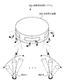
楽音発生装置600は、各操作端末800から送信される運動情報に基づき楽音発生等を行う略円柱形状の装置である(図6参照)。
図5に戻り、アンテナシステムASは、操作端末800から送信される運動情報を受信する複数のアンテナAT−1〜AT−n等によって構成されている。各アンテナAT−1〜AT−nは、楽音発生装置600の筐体内部に放射状に設けられている。かかる構成を有するアンテナシステムASは、各アンテナAT−1〜AT−nによって検出される受信レベルを比較することによって受信レベルの最も高いアンテナを特定し、特定したアンテナを識別するためのアンテナ識別情報(例えば、アンテナAT1であればA−ID1等)をスピーカ選択部64に送出する。
【0052】
無線通信部61は、操作端末800から送信される運動情報をアンテナシステムASを介して受信し、受信した運動情報を情報解析部62に出力する。
情報解析部62は、無線通信部61から供給される運動情報に対し、後述する所定の解析処理を行い、当該解析結果を演奏パラメータ決定部63に出力する。演奏パラメータ決定部63は、情報解析部62から供給される運動情報の解析結果に応じて楽音の演奏パラメータ、例えば楽音の音量やリバーブ等のパラメータを決定する。
【0053】
ステレオ発音システム100は、上記演奏パラメータ決定部63によって決定された演奏パラメータに基づく楽曲データ(MIDI(Musical Instrument Digital Interface)データ等)を受け取ると、該楽曲データに基づき楽音信号を生成し、これをステレオ音等として発音する。なお、このステレオ発音システム100は、上記本実施形態に係るステレオ発音システム100と同様、ステレオ音源装置200に接続されたミキシング装置300及びスピーカシステム400等を備えている。
【0054】
スピーカ選択部64は、アンテナシステムASから送られてくるアンテナ識別情報に基づき、スピーカシステム400を構成する複数のスピーカの中からステレオ発音に利用する1対若しくは複数対のスピーカ(以下、スピーカ対という)を選択する。詳述すると、スピーカ選択部64は、まず、アンテナシステムASから送られてくるアンテナ識別情報から操作者の位置方向を特定する。そして、スピーカ選択部64は、このようにして特定した位置方向にステレオ音等を放音させるべく、スピーカシステム400を構成する複数のスピーカの中からステレオ発音に利用するスピーカ対を選択する。
【0055】
以上説明した操作端末800及び楽音発生装置600に係る機能は、操作端末800及び楽音発生装置600に搭載されているソフトウェアとハードウェア資源とが協働することによって実現されるが、以下においては本願発明の理解に必要と思われる部分についてのみ説明し、他の部分については説明を割愛する。
【0056】
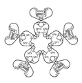
以下、動作センサMSとして3次元加速度センサを用いた場合の運動情報解析処理、演奏パラメータ決定処理、楽音発生処理、スピーカ選択処理(これらを総称して楽音発生制御処理という)を図5〜図7を参照して説明する。なお、以下の説明では、5人の操作者が各自の操作端末800を利用してある楽曲を合奏する場合を想定する(図6参照)。
【0057】
<楽音発生制御処理>
操作者は、まず、楽音発生装置600の図示せぬスイッチ等を操作することにより、合奏を行う楽曲の選択や各自が担当するパートの設定等を行う。パートの設定について一例を挙げて説明すると、例えば操作者1が第1楽器パート(ピアノパート等)を担当し、操作者2が第2楽器パート(フルートパート等)を担当し、・・・、操作者5が第5楽器パート(トランペットパート等)を担当するような設定を行う。かかる設定がなされると、楽音発生装置600のメモリ(図示略)には選択された楽曲に関するパート管理テーブルが登録される。
【0058】
このパート管理テーブルには、各操作者の操作端末を識別するための端末識別ID(例えば、操作者端末800−1であればT−ID1等)と、各操作者が担当する楽器パートを識別するためのパートID(例えば、P−ID1等)とが対応づけて登録される。
【0059】
このような設定がなされた状態において、各操作者が動作センサMSの内蔵された操作端末800を手にもって操作すると、操作方向と操作力に応じた運動情報が該操作端末800から楽音発生装置600に送信される。具体的には、図7に示すように各操作端末800における動作センサMSのx軸検出部SX、y軸検出部SYおよびz軸検出部SZからx(上下)方向の加速度αx(xは、添字)、y(左右)方向の加速度αy(yは、添字)およびz(前後)方向の加速度αz(zは、添字)を表わす信号Mx、My、Mzが出力され、該信号Mx、My、Mzの各々に上記端末識別IDが付加され、この端末識別IDの付加された信号Mx、My、Mzが運動情報として楽音発生装置600に無線送信される。
【0060】
楽音発生装置600のアンテナシステムASは、操作端末800から端末識別IDの付加された運動情報を受信すると、各アンテナAT−1〜AT−nによって検出される受信レベルを比較して受信レベルの最も高いアンテナATを特定し、特定したアンテナATを識別するためのアンテナ識別情報を生成してスピーカ選択部64に出力する一方、上記運動情報を無線通信部61に送る。無線通信部61は、アンテナシステムASを介して受信した運動情報を加速度データαx、αy、αzとして情報解析部62に出力する。
【0061】
スピーカ選択部64は、アンテナシステムASからアンテナ識別情報を受け取ると、このアンテナ識別情報から操作者の位置方向を特定する。そして、スピーカ選択部26は、特定した位置方向にステレオ音等を放音させるべく、スピーカシステム100を構成する複数のスピーカの中からステレオ発音に利用するスピーカ対を選択する。
【0062】
例えば、各操作者が図6に示すような位置に配置されている場合、スピーカ選択部64は、アンテナ識別情報等に基づき各操作者の位置を特定してスピーカ対の選択を行う。具体的には、操作者1が操作する第1楽器パートのステレオ音等については第5スピーカSP5及び第1スピーカSP1から放音されるように第1スピーカSP1と第5スピーカSP5とを選択する。同様に、スピーカ選択部26は、操作者2が操作する第2楽器パートのステレオ音等については第1スピーカSP1及び第2スピーカSP2から放音されるように第1スピーカSP2と第2スピーカSP2とを選択し、・・・操作者5が操作する第5楽器パートのステレオ音等については第4スピーカ及び第5スピーカから放音されるように第4スピーカSP4と第5スピーカSP5とを選択する。スピーカ選択部64は、このようにしてスピーカ対を選択すると、この内容をステレオ発音システム100に通知する。
【0063】
一方、情報解析部62は、無線通信部61から各軸加速度データを受け取ると、かかる各軸加速度データを解析し、下記式(1)で表わされる加速度の絶対値|α|を求める。
|α|=(αx2+αy2+αz2)1/2 ・・・(1)
【0064】
次に、情報解析部62は、加速度αx、αyと、加速度αzとを比較する。比較の結果、例えば、z方向加速度αzがx、y方向加速度αx、αyより大きいときは、操作端末800を突く「突き動作」であると判別する。
逆に、z方向加速度αzがx、y方向加速度αx、αyより小さいときには、操作端末800により空気を切りさく「切り動作」であると判別する。この場合、さらに、x、y方向加速度αx、αyの値を互いに比較し、例えばx方向加速度αxがy方向加速度αyよりも大きいときには「切り動作」の方向が「たて」(x)であると判断する。
【0065】
一方、x方向加速度αxがy方向加速度αyよりも小さいときには「切り動作」の方向が「よこ」(y) であると判断する(なお、これらはあくまで一例である)。
情報解析部62は、このようにして操作端末800の操作内容を解析すると、解析結果を演奏パラメータ決定部63に通知する。
【0066】
演奏パラメータ決定部63は、情報解析部62による解析処理の判定結果に基づいて楽曲データに対する種々の演奏パラメータを決定する。例えば、加速度絶対値|α|或いは各方向成分αx、αy、αzのうち最大を示す成分の大きさに応じて演奏データの音量を制御する。
【0067】
また、演奏パラメータ決定部63は、該判定結果に基づいて他のパラメータを次のように制御する。例えば、「たて(x方向)切り動作」の周期に応じてリバーブ(残響)の深さを制御する。これとは別に、「たて切り動作」が素早く小さい動作であると判断した場合には、アクセント等のアーティキュレーションを与え、該「たて切り動作」がゆっくり大きい動作であると判断した場合には、ピッチ(音高)を下げる(これらの制御もあくまで一例である)。
【0068】
演奏パラメータ決定部63において演奏パラメータが決定されると、決定した演奏パラメータを反映した楽曲データがステレオ発音システム100に出力される。
ステレオ発音システム100は、演奏パラメータ決定部63から供給される楽曲データに基づきステレオ音源装置200(図5参照)にて楽音信号を生成し、生成した楽音信号をミキシング装置300を介してスピーカシステム400に出力する。前述したように、スピーカ選択部64によってステレオ音等を放音すべきスピーカ対が選択されている。従って、ミキシング装置300においては、各操作者が担当する楽器パートのステレオ音等がスピーカ選択部64によって選択されたスピーカ対を介して放音されるようにミキシング操作が行われる。
【0069】
一例を挙げて説明すると、例えば第1楽器パートのステレオ音が第1ステレオ音源210(図6参照)によって生成され、第2楽器パートのステレオ音が第2ステレオ音源210によって生成され、・・・、第5楽器パートのステレオ音が第5ステレオ音源によって生成される場合、ミキシング装置300は、第1ステレオ音源210のRチャネル出力(音源1R)と第2ステレオ音源210のLチャネル出力(音源2L)とをミキシングして第1スピーカSP1に出力する。
【0070】
また、ミキシング装置300は、第2ステレオ音源210のRチャネル出力(音源2R)と第3ステレオ音源210のLチャネル出力(音源3L)とをミキシングして第2スピーカSP2に出力し、・・・第5ステレオ音源210のRチャネル出力(音源5R)と第1ステレオ音源210の1L出力(音源1L)とをミキシングして第5スピーカSP5に出力する。
【0071】
この結果、操作者1は、自己から見て左斜め前方の第5スピーカSP5からの音源1Lと右斜め前方の第1スピーカSP1からの音源1Rとを受聴して第1楽器パートに係るステレオ発音を受聴する。
同様に、操作者1の右隣に位置する操作者2は、自己から見て左斜め前方の第1スピーカSP1からの音源2Lと右斜め前方の第2スピーカSP2からの音源2Rとを受聴して第2楽器パートに係るステレオ発音を受聴し、・・・操作者4の右隣に位置する操作者5は、自己から見て左斜め前方の第4スピーカSP4と右斜め前方の第5スピーカSP5からの音源5Rとを受聴して第5楽器パートに係るステレオ発音を受聴する。このように、各操作者が担当する楽器パートのステレオ音等は、それぞれ各操作者の前方に位置するスピーカ対から放音される。よって、各操作者は自己が担当する楽器パートのステレオ音等を良好に受聴しながら合奏することができる。
【0072】
以上説明したように、本変形例に係る楽音発生制御システムによれば、操作端末800を携帯した操作者の動きを反映した楽音発生等が行われると共に、操作者の位置方向を検出し、該操作者の位置方向に対向するスピーカ対を利用して当該操作者が担当する楽器パートの楽音を発音させるため、各操作者は操作内容が反映された楽器パートの楽音を良好に受聴しながら、合奏することができる。
ここで、本変形例では演奏端末800により制御された楽音が発生し、該発生した楽音をスピーカから放音する場合について説明したが、スピーカから放音する楽音は、演奏端末800の制御によって発生される楽音に限らず、実際の楽器(キーボード、ギター等)の演奏によって発生される楽音であっても良い。なお、各スピーカから放音する楽音の種類を問わないことは、上述した本実施形態及び各変形例についても同様である。
【0073】
<変形例3>
上述した本実施形態では、複数のステレオ音源、ミキサ、スピーカを用いてステレオ発音システムを構築する場合について説明したが、1台のステレオ音源と複数のスピーカとを用いてステレオ発音システムを構築する場合にも適用可能である。
【0074】
図8は、変形例3に係るステレオ発音システム100’の構成を示す図である。
ステレオ発音システム100’は、1台のステレオ音源SS、6台のスピーカSP等によって構成されている。6台のスピーカSPは、略一定の間隔で略円形状に配置され、そのうち3台のスピーカSPがステレオ音源SSのLチャネルに接続され、残り3台のスピーカSPがステレオ音源SSのRチャネルに接続されている。なお、図8及び以下の説明では、説明の便宜上、ステレオ音源SSのLチャネルに接続されている3台のスピーカSPを適宜スピーカSP−L1〜L3と呼び、ステレオ音源SSのRチャネルに接続されている3台のスピーカSPを適宜スピーカSP−R1〜R3と呼ぶ。
【0075】
同図に示すように、6台のスピーカSPは、それぞれステレオ音源SSに接続されるチャネルがとなりあうスピーカSPとの間で異なるように配置されている。具体的には、スピーカSP−L1の右隣(反時計回り方向)には一定の間隔をおいてスピーカSP−R1が配置され、このスピーカSP−R1の右隣には一定の間隔をおいてスピーカSP−L2が配置され、・・・、スピーカSP−L3の右隣には一定の間隔をおいてスピーカSP−R3が配置されている。
【0076】
6台のスピーカがこのように受聴者の移動路に沿って略一定の間隔で配置されることにより、受聴者は図8に示す地点P1において、自己から見て左斜め前方のスピーカSP−L1からのLチャネル出力と右斜め前方のスピーカSP−R1からのRチャネル出力とを受聴してステレオ音源SSに係るステレオ発音を受聴することが可能となる。
その後、図8に示す地点P2に移動すると、受聴者はこの地点P2において、自己から見て左斜め前方のスピーカSP−R1からのRチャネル出力と右斜め前方のスピーカSP−L2からのLチャネル出力とを受聴してステレオ音源SSに係るステレオ発音を受聴する。
【0077】
同様に、図8に示す地点P3に移動すると、受聴者は自己から見て左斜め前方のスピーカSP−L2からのLチャネルと右斜め前方のスピーカSP−R2からのRチャネル出力とを受聴してステレオ音源SSに係るステレオ発音を受聴し、・・・、図7に示す地点P6に移動すると、受聴者は自己から見て左斜め前方のスピーカSP−R3からのRチャネルと右斜め前方のスピーカSP−L1からのLチャネル出力とを受聴してステレオ音源SSに係るステレオ発音を受聴する。
【0078】
このように、1台のステレオ音源と複数のスピーカを用いてステレオ発音システムを構築した場合にも、本実施形態と同様の効果、すなわち従来と比較して設置すべきスピーカの数を減らすことができるといった効果を得ることができる。すなわち、従来においては、受聴者の受聴方向毎にLチャネルスピーカ及びRチャネルスピーカからなる1対のスピーカを設置する必要があったため、図8とほぼ同様のステレオ発音を実現するためには計12台のスピーカ(Lチャネル用6台、Rチャネル用6台)が必要であったのに対し、本変形例においては5台のスピーカによってステレオ発音を受聴者に提供することができる。
【0079】
なお、本変形例においては、6台のスピーカを用いた場合について説明したが、2n(n≧2)台以上のスピーカを用いた場合にも適用可能である。
また、本変形例においては、複数のスピーカを略円形状に配置した場合について説明したが、上述した変形例1と同様、これらのスピーカを略直線上に配置しても良い。このように複数のスピーカを略直線上に配置した場合には、少なくとも3台以上のスピーカを利用すれば、本変形例と同様の効果を得ることができる。
つまり、3台以上のスピーカを1台のステレオ音源のLチャネル若しくはRチャネルに接続してステレオ発音を実現させる方法であって、前記各スピーカを略一定の間隔で配置する配置過程と、となりあうスピーカの間で前記ステレオ音源に接続されるチャネルが異なるように前記各スピーカを接続する接続過程とを具備する方法によって簡易型ステレオ発音を実現するようにしても良い。
【0080】
【発明の効果】
以上説明したように本発明によれば、スピーカの数を抑えつつも多数の受聴者に対して臨場感あるステレオ音等を提供することが可能となる。
【図面の簡単な説明】
【図1】 本実施形態におけるステレオ発音システムの概念図である。
【図2】 同実施形態に係るステレオ発音システムの構成を示す図である。
【図3】 変形例1に係るステレオ発音システムの構成を示す図である。
【図4】 変形例2に係る楽音発生制御システムを説明するための図である。
【図5】 同変形例に係る楽音発生制御システムの機能構成を示す図である。
【図6】 同変形例に係る楽音発生制御システムの概念図である。
【図7】 同変形例に係る楽音発生制御システムの動作を説明するための図である。
【図8】 変形例3に係るステレオ発音システムの構成を示す図である。
【図9】 従来におけるスピーカシステムを例示する図である。
【図10】 従来におけるスピーカシステムを例示する図である。
【図11】 従来におけるスピーカシステムを例示する図である。
【符号の説明】
100、100’、10・・・ステレオ発音システム、200、20・・・ステレオ音源装置、210、21、SS・・・ステレオ音源、300、30・・・ミキシング装置、310、31・・・ミキサ、400、40・・・スピーカシステム、410、41、SP・・・スピーカ、500・・・楽音発生制御システム、600・・・楽音発生装置、800・・・操作端末、80、61・・・無線通信部、MS・・・動作センサ、AS・・・アンテナシステム、AT・・・アンテナ、62・・・情報解析部、63・・・演奏パラメータ決定部、64・・・スピーカ選択部。[0001]
BACKGROUND OF THE INVENTION
The present invention relates to a simple stereo sound realization method, a stereo sound generation system, and a musical sound generation control system.
[0002]
[Prior art]
Currently, a stereo speaker system that is widely used is generally composed of left and right speakers installed in front of a listener at a predetermined interval. The listener appreciates the stereo sound and the like output from the speakers from the position where the pair of speakers are viewed forward and left. However, in such a speaker system, a listener cannot obtain a good stereo sound or the like unless he / she listens at the position where the pair of speakers are viewed forward in the left and right directions as described above. In other words, a good stereo sound or the like cannot be obtained when the listener moves and approaches one of the speakers or when the left and right speakers overlap in the same direction. In addition, when there are many listeners, the listeners are arranged so as to surround the speaker system. In this case, however, there is a problem that only a small number of listeners can listen to good stereo sound or the like. is there.
[0003]
In order to solve this problem, for example, a speaker system shown in FIGS. 9 and 10 has been proposed.
The speaker system shown in FIG. 9 includes speakers L1 to L8 that output an L channel of a stereo sound source (not shown) and speakers R1 to R8 that output an R channel of the stereo sound source, and these speakers are arranged on the circumference. Alternatingly arranged. Speakers R1 to R8 turn clockwise at an angle θ (θ = 57 °) with a straight line connecting the speakers from the center of the circle, and speakers L1 to L8 turn counterclockwise at the same angle θ. . And the radiation angle of the speaker which opposes and adjoins has comprised 90 degrees.
According to such a speaker system, it is possible to provide a realistic stereo sound or the like to a large number of listeners (see, for example, Patent Document 1).
Further, the speaker system shown in FIG. 10 includes a plurality of speakers arranged radially. Each speaker is appropriately supplied with a left channel audio output signal, a right channel audio output signal, and the like, and each speaker outputs audio corresponding to these signals. According to this speaker system, not only can a correct sound image be obtained in a predetermined direction, but also the reproduced sound can be heard from a direction opposite to the predetermined direction, for example, and the sound can be heard from the back side of the sound source. Such an effect can be acquired (for example, refer patent document 2).
[0004]
By the way, the said speaker system reproduces one sound source, and does not assume reproducing a plurality of sound sources. Therefore, when it is necessary to reproduce a plurality of sound sources, such as an ensemble of an electronic musical instrument, for example, the plurality of sound sources are mixed in the front stage of the speaker and reproduced by the above-described speaker system.
[0005]
The speaker system shown in FIG. 11 is an improvement of the speaker system shown in FIG. 10 so that a plurality of sound sources can be reproduced.
This speaker system is common to the speaker system shown in FIG. 10 in that each speaker is arranged in a substantially circular shape at the center of a large number of listeners, but is different in that a stereo sound or the like can be provided to the listeners. To do. More specifically, this speaker system is constituted by a first speaker SP1 to a tenth speaker SP10, and two (one pair) each of these speakers SP are arranged in various directions. Each speaker is connected to a corresponding stereo sound source. The first speaker SP1 is connected to the L channel of the first stereo sound source, while the second speaker SP2 is connected to the R channel of the first stereo sound source. The third speaker SP3 is connected to the L channel of the second stereo sound source, while the fourth speaker SP4 is connected to the R channel of the second stereo sound source, ..., the tenth speaker is connected to the R channel of the fifth sound source. ing.
[0006]
According to the speaker system of FIG. 11, since a pair of speakers SP arranged in various directions are respectively connected to the L channel and the R channel of the corresponding stereo sound source, many listeners have a sense of presence. Stereo sound and the like can be provided.
[0007]
[Patent Document 1]
Japanese Patent Laid-Open No. 2001-211495 (second page, FIGS. 1 and 2)
[Patent Document 2]
Japanese Patent Laid-Open No. 9-271095 (second and third pages, FIGS. 1 and 2)
[0008]
[Problems to be solved by the invention]
However, in the method of mixing and reproducing the sound source in the front stage of the speaker, the clarity of each sound source is deteriorated. In the speaker system shown in FIG. 11 and the like, two speakers are arranged in each direction. Therefore, a large number of speakers are required, and there is a problem that the manufacturing cost increases.
Furthermore, since it is necessary to store a large number of speakers in the housing, the housing becomes large, and there is a problem that it is inconvenient to carry.
[0009]
The present invention has been made in view of the circumstances described above, and a simple stereo sound realization method capable of providing a stereo sound with a sense of presence to a large number of listeners while suppressing the number of speakers, and The object is to provide a stereo pronunciation system.
[0010]
[Means for Solving the Problems]
In order to solve the problems described above, the present invention is a method for realizing stereo sound generation using a plurality of stereo sound sources and a number of speakers smaller than twice the number of stereo sound sources, and each speaker is arranged. An arrangement process and a mixing output process of mixing and outputting R channel output and L channel output of different stereo sound sources to at least one of the arranged speakers are provided.
[0011]
According to such a configuration, after arranging a plurality of speakers at a substantially constant interval or the like, the R channel output and the L channel output of different stereo sound sources are mixed and output to at least one speaker.
Conventionally, in order to realize stereo sound generation, it has been necessary to prepare speakers twice as many as the number of stereo sound sources, but by configuring as described above, the number of speakers necessary for stereo sound generation can be reduced. It becomes possible to reduce.
[0012]
For example, in the case of realizing stereo sound generation using two stereo sound sources, conventionally, a total of four speakers (two L channel speakers and two R channel speakers) are required. By mixing and outputting R channel output and L channel output of different sound sources to at least one speaker, the speaker plays the role of the R channel speaker of one sound source and the role of the L channel speaker of the other sound source. As a result, the number of necessary speakers can be reduced.
[0013]
In addition, the present invention is a method for realizing stereo sound generation using a plurality of stereo sound sources and a number of speakers less than twice the number of stereo sound sources. A mixing output process for mixing and outputting the R channel output and the L channel output of different stereo sound sources to at least two speakers, and in the mixing output process, the R channel of each stereo sound source Mixing is performed so that the output and the L channel output are output from a speaker.
[0014]
According to this configuration, for example, as shown in FIG. 3, after arranging a plurality of speakers on a substantially straight line at a substantially constant interval, at least two or more speakers (in FIG. 3, the second speaker and the third speaker are arranged). The R channel output and L channel output of different stereo sound sources are mixed and output to a speaker. At the time of this mixing, the mixing is performed so that the R channel output and the L channel output of each stereo sound source are output from speakers that are adjacent to each other.
[0015]
Referring to FIG. 3 as an example, the R channel output of the second stereo sound source is output from the second speaker, and the L channel output of the second stereo sound source is output from the third speaker. Here, the second speaker serves as the role of the R channel speaker of the second stereo sound source and the role of the L channel speaker of the first stereo sound source, while the third speaker serves as the role of the L channel speaker of the second stereo sound source. It also serves as the R channel speaker of the third stereo sound source. As a result, as described above, the number of speakers necessary for stereo sounding can be reduced.
[0016]
In addition, the present invention is a method for realizing stereophonic sound generation using a plurality of stereo sound sources and the same number of speakers, and an arrangement process in which the speakers are arranged in a substantially circular shape, and a different stereo for each of the arranged speakers. A mixing output process for mixing and outputting the R channel output and the L channel output of the sound source, and in the mixing output process, an output from a speaker in which the R channel output and the L channel output of each stereo sound source are combined The mixing is performed as described above.
[0017]
According to such a configuration, for example, as shown in FIG. 1, a plurality of speakers are arranged in a substantially circular shape at substantially constant intervals, and then differ from the arranged speakers (in FIG. 1, the first speaker to the fifth speaker). A stereo sound source R channel output and L channel output are mixed and output. At the time of this mixing, the mixing is performed so that the R channel output and the L channel output of each stereo sound source are output from the speakers. Referring to FIG. 1 as an example, the R channel output of the first stereo sound source is output from the first speaker, while the L channel output of the first stereo sound source is output from the fifth speaker adjacent to the first speaker.
[0018]
Similarly, the R channel output of the second stereo sound source is output from the second speaker, while the L channel output of the second stereo sound source is output from the first speaker,... While being output from 5 speakers, the L channel output of the fifth stereo sound source is output from the 4th speaker. Here, each speaker serves as both the L channel speaker of one of the two different stereo sound sources and the R channel speaker of the other stereo sound source. As a result, as described above, the number of speakers necessary for stereo sounding can be reduced.
[0019]
Further, the present invention is a stereo sound generation system including a plurality of stereo sound sources and the same number of speakers, and a mixing device that mixes R channel outputs and L channel outputs of different stereo sound sources and outputs the mixed signals to each speaker. The speakers are arranged in a substantially circular shape, and the mixing device performs the mixing so that the R channel output and the L channel output of each stereo sound source are output from speakers.
[0020]
The present invention also provides a stereo sound generation system including first to n-th stereo sound sources, wherein n is a natural number equal to or greater than 2, first to n-th mixing means, and first to n-th speakers. The n speakers are arranged in a substantially circular shape in the order of 1 to n, and when k is a natural number of 1 or more and (n−1) or less, the k th mixing means outputs the (k + 1) th R channel output of the k th stereo sound source. ) Mixing the L channel output of the stereo sound source and outputting it to the kth speaker, and the nth mixing means mixes the R channel output of the nth stereo sound source and the L channel output of the first stereo sound source to the nth speaker. It is characterized by being output to.
[0021]
In addition, the present invention provides an operator-portable operation terminal comprising a generation unit that detects movement of the operation terminal caused by the operation of the operator and generates movement information, and a transmission unit that transmits the movement information. A musical tone generation control system comprising: a musical sound generator comprising: a receiving unit that receives the exercise information; and a stereo sound generation system that generates a stereo sound based on the exercise information received by the receiving unit. The stereo sound generation system includes a plurality of stereo sound sources, the same number of speakers as the stereo sound sources, and a mixing device that mixes the R channel output and the L channel output of different stereo sound sources and outputs to each speaker. The speakers are arranged in a substantially circular shape, and the mixing device is configured to output the R channel output and the L channel of each stereo sound source. And performing the mixing so that the Le output is outputted from the adjacent speaker.
[0022]
The present invention is also a method for realizing stereo sound by connecting three or more speakers to the L channel or R channel of one stereo sound source, and arranging the speakers at substantially constant intervals. And a connection process of connecting the speakers so that the channels connected to the stereo sound source are different between adjacent speakers.
[0023]
According to this configuration, when three or more speakers are connected to either the L channel or the R channel of one stereo sound source to realize stereo sound, the speakers are arranged at substantially constant intervals, and Since the speakers are connected so that the channels connected to the stereo sound source are different between the matching speakers, the listener placed between the speakers (see points P1 to P6 in FIG. 8) is viewed from the self. Stereophonic pronunciation can be received by a pair of speakers positioned in front.
[0024]
Here, conventionally, a pair of speakers including an L channel speaker and an R channel speaker is required for each direction of the listener (see FIG. 10), but according to the above configuration, the number of necessary speakers can be reduced. It becomes possible.
Here, in the arrangement process, it is desirable to arrange the speakers at substantially constant intervals along the movement path of the listener.
[0025]
The present invention is also a method for realizing stereophonic sound by connecting 2n (n ≧ 2) or more speakers to the L channel or R channel of one stereo sound source, wherein the speakers are arranged at substantially constant intervals. And a step of connecting the speakers so that channels connected to the stereo sound source are different between adjacent speakers.
[0026]
DETAILED DESCRIPTION OF THE INVENTION
Embodiments according to the present invention will be described below.
[0027]
A. This embodiment
FIG. 1 is a conceptual diagram of a stereo
As shown in FIG. 2, the stereo
[0028]
The stereo
As shown in FIG. 1, the first to
[0029]
The
[0030]
The
[0031]
The third to
[0032]
The
Here, as described above, the
[0033]
Similarly, the listener 3 listens to the sound source 3L from the
[0034]
Thus, in the stereo
[0035]
As is clear from the above description, according to the stereo sound generation system according to the present embodiment, it is possible to provide a realistic stereo sound or the like to a large number of listeners while suppressing the number of speakers.
In this way, since it is possible to provide stereo sound or the like with a smaller number of speakers than in the past, as a result, it is possible to reduce the cost associated with the production of a stereo sound generation system, and further, a housing that accommodates each speaker Can be reduced in size and weight.
[0036]
In the above-described embodiment, in order to facilitate understanding of the description, stereo sound generation is performed by the five
[0037]
Specifically, as in the present embodiment, the speakers are arranged in a substantially circular shape in the first to nth order, and the first mixer outputs the R channel output of the first stereo sound source and the L channel output of the second stereo sound source. Are output to the first speaker. Similarly, the second mixer mixes the R channel output of the second stereo sound source and the L channel output of the third stereo sound source and outputs them to the second speaker,..., The nth mixer is the R of the nth stereo sound source. The channel output and the L channel output of the first stereo sound source are mixed and output to the nth speaker. Thereby, each listener can listen to stereophonic sound through a pair of speakers positioned in front of him / her.
[0038]
B. Modified example
Although one embodiment of the present invention has been described above, the above embodiment is merely an example, and various modifications can be made to the above embodiment without departing from the spirit of the present invention. As modifications, for example, the following can be considered.
[0039]
<
In the above-described embodiment, the case where a plurality of speakers are arranged in a substantially circular shape has been described. However, for example, they may be arranged in a substantially linear shape.
FIG. 3 is a diagram illustrating a configuration of the stereo sound generation system 10 according to the first modification.
The stereo sound generation system 10 includes a mixing device 30 connected to a stereo sound source device 20 including first to third
The mixing device 30 is composed of a
[0040]
The
[0041]
The
[0042]
On the other hand, the R channel output (sound source 1R) of the first
[0043]
Here, the
Similarly, the
[0044]
Thus, also in the stereo sound generation system according to the present modification, the number of speakers can be reduced as compared with the conventional one. That is, conventionally, in order to realize stereo sound generation, two speakers are required for each stereo sound source, so it has been necessary to prepare twice as many speakers as the number of stereo sound sources to be reproduced (see FIG. 11), in the present modification, it is possible to realize sound generation of a plurality of stereo sound sources with at least a number of speakers smaller than twice the number of stereo sound sources.
[0045]
In addition, in this modification, although the aspect using the three
[0046]
<
FIG. 4 is a diagram for explaining a tone generation control system according to the second modification.
The musical sound generation control system 500 is a system operated in a music classroom, school, house, hall, etc., and a plurality of operations for each user to produce a musical sound generator 600 and musical sound generation by the musical sound generator 600. Terminal 800-N (N ≧ 1; N = 5 is assumed in this modification).
[0047]
In the tone generation control system 500 according to this modification, the stereo sound generation system according to the present embodiment is employed. Hereinafter, a detailed configuration of such a musical tone generation control system will be described.
[0048]
<Functional configuration of musical tone generation control system 500>
FIG. 5 is a diagram showing a functional configuration of a musical sound generation control system 500 constructed in a certain music classroom or the like. In the following description, operation terminal 800-1 to operation terminal 800-N are simply referred to as
[0049]
The
The motion sensor MS is a sensor that detects motion based on the motion of the operator carrying the
[0050]
The
[0051]
The musical sound generating device 600 is a substantially cylindrical device that generates musical sounds based on exercise information transmitted from each operation terminal 800 (see FIG. 6).
Returning to FIG. 5, the antenna system AS is configured by a plurality of antennas AT-1 to AT-n and the like that receive motion information transmitted from the
[0052]
The
The
[0053]
When the stereo
[0054]
The
[0055]
The functions related to the
[0056]
Hereinafter, motion information analysis processing, performance parameter determination processing, musical tone generation processing, and speaker selection processing (collectively referred to as musical tone generation control processing) when a three-dimensional acceleration sensor is used as the motion sensor MS are shown in FIGS. Will be described with reference to FIG. In the following description, it is assumed that five operators play a piece of music using their respective operation terminals 800 (see FIG. 6).
[0057]
<Musical sound generation control processing>
First, the operator operates a switch or the like (not shown) of the musical sound generator 600 to select a music piece to be played or to set a part for which each person is in charge. An example of the setting of the parts will be described below. For example, the
[0058]
In this part management table, a terminal identification ID (for example, T-ID1 in the case of the operator terminal 800-1) for identifying each operator's operation terminal and a musical instrument part for which each operator is in charge are identified. Part ID (for example, P-ID1 etc.) is registered in association with each other.
[0059]
In a state where such settings are made, when each operator operates the
[0060]
When the antenna system AS of the musical tone generator 600 receives the exercise information to which the terminal identification ID is added from the
[0061]
When the
[0062]
For example, when each operator is arranged at a position as shown in FIG. 6, the
[0063]
On the other hand, when the
| Α | = (αx 2 + Αy 2 + Αz 2 ) 1/2 ... (1)
[0064]
Next, the
Conversely, when the z-direction acceleration αz is smaller than the x- and y-direction accelerations αx and αy, it is determined that the
[0065]
On the other hand, when the x-direction acceleration αx is smaller than the y-direction acceleration αy, it is determined that the direction of the “cutting operation” is “weft” (y) (note that these are merely examples).
When the
[0066]
The performance
[0067]
The performance
[0068]
When the performance parameter is determined by the performance
The stereo
[0069]
For example, the stereo sound of the first instrument part is generated by the first stereo sound source 210 (see FIG. 6), the stereo sound of the second instrument part is generated by the second
[0070]
The mixing
[0071]
As a result, the
Similarly, the
[0072]
As described above, according to the musical sound generation control system according to the present modification, musical sound generation reflecting the movement of the operator carrying the
Here, in this modified example, the case where a musical sound controlled by the
[0073]
<Modification 3>
In the present embodiment described above, the case where a stereo sound generation system is constructed using a plurality of stereo sound sources, mixers, and speakers has been described. However, when a stereo sound generation system is constructed using a single stereo sound source and a plurality of speakers. It is also applicable to.
[0074]
FIG. 8 is a diagram illustrating a configuration of a stereo
The stereo
[0075]
As shown in the figure, the six speakers SP are arranged so as to be different from the speakers SP each having a channel connected to the stereo sound source SS. Specifically, the speaker SP-R1 is arranged at a certain interval on the right side (counterclockwise direction) of the speaker SP-L1, and the speaker SP-R1 is arranged at a certain interval on the right side. A speaker SP-L2 is arranged, and a speaker SP-R3 is arranged at a certain interval on the right side of the speaker SP-L3.
[0076]
The six speakers are arranged at substantially constant intervals along the listener's moving path in this way, so that the listener can see the speaker SP-L1 diagonally to the left when viewed from the point P1 shown in FIG. It is possible to listen to the stereo sound produced by the stereo sound source SS by listening to the L channel output from the right and the R channel output from the speaker SP-R1 diagonally forward to the right.
Thereafter, when the user moves to a point P2 shown in FIG. 8, the listener at this point P2 sees the R channel output from the speaker SP-R1 diagonally forward left and the L channel from the speaker SP-L2 diagonally forward right. Listen to the output and listen to the stereo sound of the stereo sound source SS.
[0077]
Similarly, when moving to the point P3 shown in FIG. 8, the listener listens to the L channel from the speaker SP-L2 diagonally forward left and the R channel output from the speaker SP-R2 diagonally forward right when viewed from the self. Then, when listening to the stereophonic sound of the stereo sound source SS, and moving to the point P6 shown in FIG. 7, the listener sees the R channel from the speaker SP-R3 diagonally left front and the diagonally right front when viewed from the self. The user hears the L channel output from the speaker SP-L1 and listens to the stereo sound of the stereo sound source SS.
[0078]
Thus, even when a stereo sound generation system is constructed using one stereo sound source and a plurality of speakers, the same effect as this embodiment, that is, the number of speakers to be installed can be reduced as compared with the conventional one. The effect that it can do. That is, in the prior art, it was necessary to install a pair of speakers including an L channel speaker and an R channel speaker for each listening direction of the listener. While two speakers (6 for L channel and 6 for R channel) are necessary, in this modification, stereo sound can be provided to the listener by using five speakers.
[0079]
In addition, in this modification, although the case where six speakers were used was demonstrated, it is applicable also when using 2n (n> = 2) or more speakers.
Moreover, in this modification, although the case where the several speaker was arrange | positioned in the substantially circular shape was demonstrated, you may arrange | position these speakers on a substantially straight line like the
That is, it is a method for realizing stereo sound generation by connecting three or more speakers to the L channel or R channel of one stereo sound source, and is an arrangement process in which the speakers are arranged at substantially constant intervals. Simple stereo sound generation may be realized by a method including a connection process of connecting the speakers so that channels connected to the stereo sound source are different between the speakers.
[0080]
【The invention's effect】
As described above, according to the present invention, it is possible to provide a realistic stereo sound or the like to a large number of listeners while suppressing the number of speakers.
[Brief description of the drawings]
FIG. 1 is a conceptual diagram of a stereo sound generation system in the present embodiment.
FIG. 2 is a diagram showing a configuration of a stereo sound generation system according to the embodiment.
FIG. 3 is a diagram illustrating a configuration of a stereo sound generation system according to a first modification.
FIG. 4 is a diagram for explaining a tone generation control system according to a second modification.
FIG. 5 is a diagram showing a functional configuration of a tone generation control system according to the modification.
FIG. 6 is a conceptual diagram of a tone generation control system according to the modification.
FIG. 7 is a diagram for explaining the operation of the tone generation control system according to the modification.
FIG. 8 is a diagram illustrating a configuration of a stereo sound generation system according to a third modification.
FIG. 9 is a diagram illustrating a conventional speaker system.
FIG. 10 is a diagram illustrating a conventional speaker system.
FIG. 11 is a diagram illustrating a conventional speaker system.
[Explanation of symbols]
100, 100 ', 10 ... stereo sound generation system, 200, 20 ... stereo sound source device, 210, 21, SS ... stereo sound source, 300, 30 ... mixing device, 310, 31 ... mixer , 400, 40 ... speaker system, 410, 41, SP ... speaker, 500 ... musical tone generation control system, 600 ... musical tone generator, 800 ... operation terminal, 80, 61 ... Wireless communication unit, MS ... motion sensor, AS ... antenna system, AT ... antenna, 62 ... information analysis unit, 63 ... performance parameter determination unit, 64 ... speaker selection unit.
Claims (8)
各スピーカを配置する配置過程と、
配置したスピーカの少なくとも1台以上のスピーカに対し、異なるステレオ音源のRチャネル出力とLチャネル出力とをミキシングして出力するミキシング出力過程と
を備えたことを特徴とする簡易型ステレオ発音実現方法。A method of realizing stereophonic sound using a plurality of stereo sound sources and a number of speakers less than twice the number of stereo sound sources,
The placement process of placing each speaker;
A method for realizing a simple stereo sound generation, comprising: a mixing output step of mixing and outputting R channel outputs and L channel outputs of different stereo sound sources to at least one of the arranged speakers.
各スピーカを配置する配置過程と、
配置したスピーカの少なくとも2台以上のスピーカに対し、異なるステレオ音源のRチャネル出力とLチャネル出力とをミキシングして出力するミキシング出力過程とを備え、
前記ミキシング出力過程にあっては、各ステレオ音源のRチャネル出力とLチャネル出力とがとなりあうスピーカから出力されるようにミキシングを行うことを特徴とする簡易型ステレオ発音実現方法。A method of realizing stereophonic sound using a plurality of stereo sound sources and a number of speakers less than twice the number of stereo sound sources,
The placement process of placing each speaker;
A mixing output process of mixing and outputting R channel output and L channel output of different stereo sound sources to at least two or more speakers arranged;
In the mixing output process, a simple stereo sound realization method characterized in that mixing is performed so that the R channel output and the L channel output of each stereo sound source are output from speakers.
各スピーカを略円形に配置する配置過程と、
配置した各スピーカに対し、異なるステレオ音源のRチャネル出力とLチャネル出力とをミキシングして出力するミキシング出力過程とを備え、
前記ミキシング出力過程にあっては、各ステレオ音源のRチャネル出力とLチャネル出力とがとなりあうスピーカから出力されるようにミキシングを行うことを特徴とする簡易型ステレオ発音実現方法。A method for realizing stereo sound generation using a plurality of stereo sound sources and the same number of speakers,
An arrangement process of arranging the speakers in a substantially circular shape,
A mixing output process for mixing and outputting the R channel output and the L channel output of different stereo sound sources for each arranged speaker,
In the mixing output process, a simple stereo sound realization method characterized in that mixing is performed so that the R channel output and the L channel output of each stereo sound source are output from speakers.
前記各スピーカは、略円形に配置され、
前記ミキシング装置は、前記各ステレオ音源のRチャネル出力とLチャネル出力とがとなりあうスピーカから出力されるように前記ミキシングを行うことを特徴とするステレオ発音システム。A stereo sound generation system comprising a plurality of stereo sound sources and the same number of speakers, and a mixing device that mixes R channel outputs and L channel outputs of different stereo sound sources and outputs them to each speaker,
Each of the speakers is arranged in a substantially circular shape,
The stereo sound generation system according to claim 1, wherein the mixing device performs the mixing so that an R channel output and an L channel output of each stereo sound source are output from a speaker.
第1〜第nスピーカは、1〜nの順序で略円形に配置され、
kを1以上(n−1)以下の自然数とした場合、第kミキシング手段は、第kステレオ音源のRチャネル出力と第(k+1)ステレオ音源のLチャネル出力とをミキシングして第kスピーカに出力し、
第nミキシング手段は、第nステレオ音源のRチャネル出力と第1ステレオ音源のLチャネル出力とをミキシングして第nスピーカに出力することを特徴とするステレオ発音システム。A stereo sound generation system including first to n-th stereo sound sources, wherein n is a natural number equal to or greater than 2, first to n-th mixing means, and first to n-th speakers,
The first to nth speakers are arranged in a substantially circular shape in the order of 1 to n,
When k is a natural number greater than or equal to 1 and less than or equal to (n−1), the kth mixing means mixes the R channel output of the kth stereo sound source and the L channel output of the (k + 1) th stereo sound source to the kth speaker. Output,
The nth mixing means mixes the R channel output of the nth stereo sound source and the L channel output of the first stereo sound source and outputs the mixed sound to the nth speaker.
前記運動情報を受信する受信手段と、前記受信手段によって受信された前記運動情報に基づいてステレオ音を発音するステレオ発音システムとを具備する楽音発生装置とを備えた楽音発生制御システムであって、
前記ステレオ発音システムは、複数のステレオ音源と、前記ステレオ音源と同数のスピーカと、それぞれ異なるステレオ音源のRチャネル出力とLチャネル出力とをミキシングして各スピーカへ出力するミキシング装置とを具備し、
前記各スピーカは、略円形に配置され、
前記ミキシング装置は、前記各ステレオ音源のRチャネル出力とLチャネル出力とがとなりあうスピーカから出力されるように前記ミキシングを行うことを特徴とする楽音発生制御システム。An operator-portable operation terminal comprising: generation means for detecting movement of the operation terminal caused by the operation of the operator and generating movement information; and transmission means for transmitting the movement information;
A musical sound generation control system comprising: a receiving means for receiving the exercise information; and a musical sound generator comprising a stereo sound generation system for generating a stereo sound based on the exercise information received by the receiving means,
The stereo sound generation system includes a plurality of stereo sound sources, the same number of speakers as the stereo sound sources, and a mixing device that mixes the R channel output and the L channel output of different stereo sound sources and outputs to each speaker.
Each of the speakers is arranged in a substantially circular shape,
The musical tone generation control system, wherein the mixing device performs the mixing so that an R channel output and an L channel output of each stereo sound source are output from speakers.
前記各スピーカを略一定の間隔で略円形に配置する過程と、
となりあうスピーカの間で前記ステレオ音源に接続されるチャネルが異なるように前記各スピーカを接続する過程と
を具備することを特徴とする簡易型ステレオ発音実現方法。A method of realizing stereo sound generation by connecting 2n (n ≧ 2) or more speakers to the L channel or R channel of one stereo sound source,
Arranging each speaker in a substantially circular shape at substantially constant intervals;
And a step of connecting the speakers so that the channels connected to the stereo sound source are different between adjacent speakers.
Priority Applications (2)
| Application Number | Priority Date | Filing Date | Title |
|---|---|---|---|
| JP2003124193A JP4096801B2 (en) | 2003-04-28 | 2003-04-28 | Simple stereo sound realization method, stereo sound generation system and musical sound generation control system |
| US10/834,817 US7512246B2 (en) | 2003-04-28 | 2004-04-28 | Stereo sounding method, stereo sounding system, and musical tone generation control system |
Applications Claiming Priority (1)
| Application Number | Priority Date | Filing Date | Title |
|---|---|---|---|
| JP2003124193A JP4096801B2 (en) | 2003-04-28 | 2003-04-28 | Simple stereo sound realization method, stereo sound generation system and musical sound generation control system |
Publications (2)
| Publication Number | Publication Date |
|---|---|
| JP2004328662A JP2004328662A (en) | 2004-11-18 |
| JP4096801B2 true JP4096801B2 (en) | 2008-06-04 |
Family
ID=33296699
Family Applications (1)
| Application Number | Title | Priority Date | Filing Date |
|---|---|---|---|
| JP2003124193A Expired - Fee Related JP4096801B2 (en) | 2003-04-28 | 2003-04-28 | Simple stereo sound realization method, stereo sound generation system and musical sound generation control system |
Country Status (2)
| Country | Link |
|---|---|
| US (1) | US7512246B2 (en) |
| JP (1) | JP4096801B2 (en) |
Families Citing this family (7)
| Publication number | Priority date | Publication date | Assignee | Title |
|---|---|---|---|---|
| US20050035246A1 (en) * | 2003-07-28 | 2005-02-17 | Coleman Ludlow Peter | Remotely controllable revolving support for speaker |
| US20060088170A1 (en) * | 2004-10-22 | 2006-04-27 | Esterberg Dennis R | Audio appliance |
| JP4867516B2 (en) * | 2006-08-01 | 2012-02-01 | ヤマハ株式会社 | Audio conference system |
| JP4937942B2 (en) * | 2008-02-27 | 2012-05-23 | シャープ株式会社 | Audio reproduction device, audio reproduction method, audio reproduction system, control program, and computer-readable recording medium |
| AU2009246252B2 (en) * | 2008-05-15 | 2014-12-18 | Jamhub Corporation | Systems for combining inputs from electronic musical instruments and devices |
| JP2012151530A (en) * | 2011-01-14 | 2012-08-09 | Ari:Kk | Binaural audio reproduction system and binaural audio reproduction method |
| JP6248930B2 (en) * | 2012-07-13 | 2017-12-20 | ソニー株式会社 | Information processing system and program |
Family Cites Families (9)
| Publication number | Priority date | Publication date | Assignee | Title |
|---|---|---|---|---|
| US5290964A (en) * | 1986-10-14 | 1994-03-01 | Yamaha Corporation | Musical tone control apparatus using a detector |
| US5170002A (en) * | 1987-12-24 | 1992-12-08 | Yamaha Corporation | Motion-controlled musical tone control apparatus |
| JPH0299994A (en) * | 1988-10-06 | 1990-04-11 | Yamaha Corp | Musical sound controller |
| JPH09271095A (en) | 1996-03-29 | 1997-10-14 | Aiwa Co Ltd | Acoustic device |
| US6011851A (en) * | 1997-06-23 | 2000-01-04 | Cisco Technology, Inc. | Spatial audio processing method and apparatus for context switching between telephony applications |
| US7183480B2 (en) | 2000-01-11 | 2007-02-27 | Yamaha Corporation | Apparatus and method for detecting performer's motion to interactively control performance of music or the like |
| JP2001211495A (en) | 2000-01-25 | 2001-08-03 | Noriji Ooishi | Omnidirectional stereo speaker system |
| US7206421B1 (en) * | 2000-07-14 | 2007-04-17 | Gn Resound North America Corporation | Hearing system beamformer |
| JP3948242B2 (en) | 2001-10-17 | 2007-07-25 | ヤマハ株式会社 | Music generation control system |
-
2003
- 2003-04-28 JP JP2003124193A patent/JP4096801B2/en not_active Expired - Fee Related
-
2004
- 2004-04-28 US US10/834,817 patent/US7512246B2/en not_active Expired - Fee Related
Also Published As
| Publication number | Publication date |
|---|---|
| JP2004328662A (en) | 2004-11-18 |
| US7512246B2 (en) | 2009-03-31 |
| US20040213412A1 (en) | 2004-10-28 |
Similar Documents
| Publication | Publication Date | Title |
|---|---|---|
| US10231054B2 (en) | Headphones and method for producing headphones | |
| JP3948242B2 (en) | Music generation control system | |
| EP1900252B1 (en) | Recording, synthesis and reproduction of sound fields in an enclosure | |
| US10524055B2 (en) | Earphone and method for producing an earphone | |
| US6801630B1 (en) | Device for and method of mixing audio signals | |
| CN101770771B (en) | Electronic keyboard instrument | |
| US20170251324A1 (en) | Reproducing audio signals in a motor vehicle | |
| JP4096801B2 (en) | Simple stereo sound realization method, stereo sound generation system and musical sound generation control system | |
| CN1672463A (en) | Audio processing system | |
| JP2007124380A (en) | Stereophonic output system, stereophonic output method, and program for stereophonic output | |
| US20230362545A1 (en) | Microphone, method for recording an acoustic signal, reproduction apparatus for an acoustic signal or method for reproducing an acoustic signal | |
| JP2019080188A (en) | Audio system and vehicle | |
| JP5169300B2 (en) | Music signal output device | |
| JP2000078700A5 (en) | ||
| JP2004088608A (en) | Mixing device | |
| US6399868B1 (en) | Sound effect generator and audio system | |
| CN116982322A (en) | Information processing device, information processing method, and program | |
| JPH11187498A (en) | Stereophonic sound reproducing device | |
| US20090097675A1 (en) | Sound providing system | |
| KR20050083389A (en) | Apparatus of karaoke based on multi channel and method thereof | |
| Moulton | The creation of musical sounds for playback through loudspeakers | |
| JPH1070798A (en) | Three-dimensional sound reproducing device | |
| EP1366639A2 (en) | Surround sound system | |
| JPH0729359A (en) | Composition, song writing and receiver | |
| Braasch et al. | A" Tonmeister" approach to the positioning of sound sources in a multichannel audio system |
Legal Events
| Date | Code | Title | Description |
|---|---|---|---|
| A621 | Written request for application examination |
Free format text: JAPANESE INTERMEDIATE CODE: A621 Effective date: 20060123 |
|
| A977 | Report on retrieval |
Free format text: JAPANESE INTERMEDIATE CODE: A971007 Effective date: 20071105 |
|
| TRDD | Decision of grant or rejection written | ||
| A01 | Written decision to grant a patent or to grant a registration (utility model) |
Free format text: JAPANESE INTERMEDIATE CODE: A01 Effective date: 20080219 |
|
| A61 | First payment of annual fees (during grant procedure) |
Free format text: JAPANESE INTERMEDIATE CODE: A61 Effective date: 20080303 |
|
| R150 | Certificate of patent or registration of utility model |
Free format text: JAPANESE INTERMEDIATE CODE: R150 |
|
| FPAY | Renewal fee payment (event date is renewal date of database) |
Free format text: PAYMENT UNTIL: 20110321 Year of fee payment: 3 |
|
| FPAY | Renewal fee payment (event date is renewal date of database) |
Free format text: PAYMENT UNTIL: 20110321 Year of fee payment: 3 |
|
| FPAY | Renewal fee payment (event date is renewal date of database) |
Free format text: PAYMENT UNTIL: 20120321 Year of fee payment: 4 |
|
| FPAY | Renewal fee payment (event date is renewal date of database) |
Free format text: PAYMENT UNTIL: 20130321 Year of fee payment: 5 |
|
| FPAY | Renewal fee payment (event date is renewal date of database) |
Free format text: PAYMENT UNTIL: 20140321 Year of fee payment: 6 |
|
| LAPS | Cancellation because of no payment of annual fees |