JP4095592B2 - Information processing apparatus, information processing method, and program - Google Patents
Information processing apparatus, information processing method, and program Download PDFInfo
- Publication number
- JP4095592B2 JP4095592B2 JP2004231426A JP2004231426A JP4095592B2 JP 4095592 B2 JP4095592 B2 JP 4095592B2 JP 2004231426 A JP2004231426 A JP 2004231426A JP 2004231426 A JP2004231426 A JP 2004231426A JP 4095592 B2 JP4095592 B2 JP 4095592B2
- Authority
- JP
- Japan
- Prior art keywords
- link
- partial rectangular
- distance
- rectangular area
- partial
- Prior art date
- Legal status (The legal status is an assumption and is not a legal conclusion. Google has not performed a legal analysis and makes no representation as to the accuracy of the status listed.)
- Expired - Fee Related
Links
Images


Classifications
-
- G—PHYSICS
- G06—COMPUTING; CALCULATING OR COUNTING
- G06F—ELECTRIC DIGITAL DATA PROCESSING
- G06F9/00—Arrangements for program control, e.g. control units
- G06F9/06—Arrangements for program control, e.g. control units using stored programs, i.e. using an internal store of processing equipment to receive or retain programs
-
- G—PHYSICS
- G06—COMPUTING; CALCULATING OR COUNTING
- G06F—ELECTRIC DIGITAL DATA PROCESSING
- G06F40/00—Handling natural language data
- G06F40/10—Text processing
- G06F40/103—Formatting, i.e. changing of presentation of documents
Description
本発明は、ドキュメント上の複数のオブジェクトにデータを流し込み、該オブジェクトのレイアウトを該データに応じて所定の制御条件のもとに制御することにより、ドキュメントの生成を行う情報処理装置において、該オブジェクトのレイアウトの制御条件を設定するための情報処理技術に関するものである。 The present invention provides an information processing apparatus for generating a document by flowing data into a plurality of objects on a document and controlling the layout of the object under a predetermined control condition according to the data. The present invention relates to an information processing technique for setting the layout control conditions.
近年、商品の多品種化で商品寿命が短くなっていること、インターネット利用の普及による消費者のカスタマイズサービス指向などの要因からCRM(Customer Relationship Management)、One−to−Oneマーケティングの必要性が注目されている。これらの手法は、顧客満足度を高め、顧客の開拓や囲い込みを目指すという目的に対して非常に効果的なものである。 In recent years, the need for CRM (Customer Relationship Management) and One-to-One marketing has attracted attention due to factors such as the shortening of product lifespan due to the increase in the number of products and the orientation of consumer customization services due to the spread of Internet usage. Has been. These methods are very effective for the purpose of increasing customer satisfaction and aiming to develop and lock in customers.
One−to−Oneマーケティングはデータベース・マーケティングの一種で、顧客の年齢、性別、趣味、嗜好、購買履歴等の個人属性情報をデータベース化し、その内容を分析、顧客のニーズに合った提案を行うものであり、その代表的な手法としてバリアブルプリントが挙げられる。ここ最近ではDTP(デスクトップパブリッシング)技術の進展とデジタル印刷装置の普及に伴って、文書を顧客毎にカスタマイズして出力するバリアブルプリントシステムが開発され、顧客毎に異なる量のコンテンツを最適にレイアウトすることが求められるようになった。 One-to-one marketing is a type of database marketing that creates a database of personal attribute information such as customer age, gender, hobbies, preferences, purchase history, etc., analyzes the content, and makes proposals that meet customer needs As a representative method, variable printing can be mentioned. Recently, with the advancement of DTP (desktop publishing) technology and the spread of digital printing devices, a variable print system that customizes and outputs documents for each customer has been developed to optimally lay out different amounts of content for each customer. It came to be demanded.
一般に、バリアブルプリントシステムにおいてそのようなカスタマイズ文書を作成する際には、ドキュメント上にコンテナをレイアウトする。コンテナとはオブジェクトの1つでありデータベース化されたコンテンツ(描画内容)を描画するための部分領域をいう(フィールド領域と呼ばれることもある)。すなわち、ドキュメント上にこのようなコンテナをレイアウトし、データベースとコンテナとを関連付ける(データベースの各コンテンツと各コンテナとを関連付ける)といった作業により、カスタマイズ文書(ドキュメント)を作成する。 Generally, when creating such a customized document in the variable print system, a container is laid out on the document. A container is one of objects and is a partial area for drawing contents (drawing contents) stored in a database (sometimes called a field area). That is, a customized document (document) is created by laying out such a container on a document and associating the database with the container (associating each content of the database with each container).
しかし、バリアブルプリントシステムの場合、テキストおよびイメージのコンテナのサイズが固定であるため、データベース内のデータがコンテナに挿入されたときに、データ量がコンテナサイズより多いとテキストのオーバーラップおよびイメージのクリッピングが発生し、またデータ量がコンテナサイズより小さいとコンテナに隙間が空いてしまうという問題があった。 However, in the case of variable print systems, the size of text and image containers is fixed, so when data in the database is inserted into the container, if the amount of data exceeds the container size, text overlap and image clipping When the amount of data is smaller than the container size, there is a problem that a gap is left in the container.
かかる問題を解決するために、自動レイアウトシステムが提案されている。自動レイアウトシステムとは、コンテンツによってコンテナのレイアウトを動的に変更するシステムであり、挿入されるテキストおよびイメージのデータ量に応じてコンテナサイズを可変に設定することが可能である。 In order to solve such a problem, an automatic layout system has been proposed. The automatic layout system is a system that dynamically changes the layout of a container according to content, and the container size can be variably set according to the amount of text and image data to be inserted.
具体的には、当該自動レイアウトシステムにおいて、コンテナのサイズを可変とし、挿入されるデータ量に応じてコンテナのサイズを大きくしてレイアウトしたり、またテキストの場合にあっては、コンテナ内のフォントのサイズを可変とし、挿入されるデータ量に応じてフォントのサイズを縮小してレイアウトしたりすることにより、コンテナ内に入りきらないデータ量のテキストが挿入された場合でも、コンテナ内に全てのテキストを表示させることを可能にしている。 Specifically, in the automatic layout system, the container size is variable and the container size is increased according to the amount of data to be inserted. In the case of text, the font in the container is used. By changing the font size and reducing the font size according to the amount of data to be inserted, even if text with an amount of data that does not fit in the container is inserted, The text can be displayed.
しかし、コンテナのサイズを可変とするとデータ量が大きい場合、同じドキュメント上の他のコンテナに重なってレイアウトされてしまったり、あるいはコンテナ同士が重なることがないように、コンテナの大きさを固定しフォントのサイズを可変とすると、テキストのデータ量が大きい場合、フォントサイズが小さくなりすぎてレイアウトされてしまうといったことが起こりえる。 However, if the container size is variable, if the amount of data is large, the size of the container is fixed and the font is fixed so that other containers on the same document are not laid out or overlap each other. If the size of the text is variable, if the amount of text data is large, the font size may be too small and the text may be laid out.
このため、上記自動レイアウトシステムには、隣接するコンテナ同士を関連付けるリンク機能(オブジェクトにデータを流し込んだ場合のレイアウトが、該オブジェクトに隣接する他のオブジェクトのレイアウトに基づいて定まるよう、隣接するオブジェクト間を関連付けるための機能)が備えられており、特定のコンテナのサイズが大きくなった場合でも、隣接するコンテナのサイズを自動的に小さくレイアウトすることで、上記問題の解決が図られている(例えば、下記特許文献1参照)。
しかしながら、上記自動レイアウトシステムでは、ドキュメント上に複数のコンテナを配置し、それぞれのコンテナ同士を関連付けるにあたり、ユーザは各コンテナ間のリンクの設定を1つずつ手作業で行っていかなければならなかった。しかし、上述したOne−to−Oneマーケティングでは顧客のニーズに合わせてカタログやパンフレットを作成するため、顧客によっては多くの情報を掲載する必要があり、コンテンツが流し込まれるコンテナ数の増加に伴って、コンテナ間を関連付けるリンクの数も増加することが考えられる。その際に、上記技術のようにコンテナ間を関連付けるリンクの設定を1つ1つ手作業で行っていては、当該設定作業の負荷が増大してしまうといった問題があった。 However, in the automatic layout system described above, when arranging a plurality of containers on a document and associating the containers with each other, the user has to manually set the links between the containers one by one. . However, in the above-mentioned one-to-one marketing, in order to create catalogs and pamphlets according to the needs of customers, it is necessary for some customers to post a lot of information. With the increase in the number of containers into which content is poured, It is conceivable that the number of links that associate containers will also increase. At that time, if the setting of the link for associating the containers is performed manually one by one as in the above technique, there is a problem that the load of the setting work increases.
本発明は、上記課題に鑑みてなされたものであり、各コンテナ間を関連付けるリンクを設定する際に、ユーザがあらかじめ設定した所定の距離内に複数のオブジェクトが含まれた場合に自動的にリンクを設定されることによって、レイアウトシステムにおけるユーザの設定作業の効率化を図ることを目的とする。 The present invention has been made in view of the above problems, and when setting a link for associating each container, a link is automatically provided when a plurality of objects are included within a predetermined distance set in advance by the user. The purpose of this is to improve the efficiency of the user's setting work in the layout system.
上記の目的を達成するために本発明に係る情報処理方法は以下のような構成を備える。即ち、
ドキュメント上の第1部分矩形領域を構成する辺と、該辺に対向する第2部分矩形領域を構成する辺との間に、リンクを作成し、データが前記部分矩形領域に入力された場合に、該作成されたリンクに応じて、該第1部分矩形領域を構成する辺の位置と該辺に対向する該第2部分矩形領域の辺の位置とを規定することにより、該第1部分矩形領域と該第2部分矩形領域のレイアウトを決定する情報処理装置における情報処理方法であって、
前記リンクを作成するためのリンク作成条件として、ユーザからの指示に応じて、前記第1部分矩形領域を構成する辺と、該辺に対向する前記第2部分矩形領域の辺との間の距離を設定する設定工程と、
ユーザからの指示に応じて、作成するリンクの種類として、固定サイズのリンクまたは可変サイズのリンクを設定するリンク設定工程と、
前記ドキュメント上における前記第1部分矩形領域を構成する辺の位置を取得する取得工程と、
前記取得工程において取得された位置に基づいて、前記第1部分矩形領域を構成する辺と、前記ドキュメント上に既に配置されている第2部分矩形領域の、該第1部分矩形領域を構成する辺に対向する辺との間の距離を計算する計算工程と、
前記計算工程において計算された前記距離と前記リンク作成条件とを用いて、前記第1部分矩形領域を構成する辺と、該辺に対向する前記第2部分矩形領域を構成する辺との間に前記リンクを作成すべきか否かを判定する判定工程と、
前記判定工程において、前記リンクを作成すべきと判定された場合に、前記リンク設定工程において設定された種類のリンクを作成するリンク作成工程とを備える。
In order to achieve the above object, an information processing method according to the present invention comprises the following arrangement. That is,
And sides of the first partial rectangular area of the document, between the sides of the second partial rectangular region opposite the 該辺, to create a link, if the data is input to the partial rectangular region The first partial rectangle is defined by defining the position of the side constituting the first partial rectangular area and the position of the side of the second partial rectangular area facing the side according to the created link . An information processing method in an information processing apparatus for determining a layout of an area and the second partial rectangular area ,
As a link creation condition for creating the link , according to an instruction from the user, a distance between a side constituting the first partial rectangular region and a side of the second partial rectangular region facing the side A setting process for setting
In accordance with an instruction from the user, as a type of link to be created, a link setting step for setting a fixed size link or a variable size link,
An acquisition step of acquiring a position of an edge constituting the first partial rectangular area on the document;
Based on the position acquired in the acquisition step, sides forming the sides of the said first partial rectangular region, the second partial rectangular area that is already disposed on the document, the first partial rectangular area A calculation step for calculating the distance between the side opposite to
Using said the calculated the distance and the link creation condition in the calculating step, the sides of the said first partial rectangular area between the sides of the second partial rectangular region facing the該辺 A determination step of determining whether or not to create the link;
A link creating step for creating the type of link set in the link setting step when it is determined in the determining step that the link should be created.
本発明によれば、複数のオブジェクトを関連付けるリンクを自動的に設定することができるようになるので、自動レイアウトシステムにおけるユーザの作業の効率化を図ることが可能となる。 According to the present invention, since a link for associating a plurality of objects can be automatically set, it is possible to improve the efficiency of the user's work in the automatic layout system.
はじめに本実施形態の概要について説明する。一般に自動レイアウトシステムにおけるドキュメントの作成は、レイアウト編集処理と自動レイアウト処理とに区分けできる。前者はコンテナをドキュメント上に配置するとともに、データを流し込んだ場合にどのようにコンテナのレイアウトを制御するか、その制御条件を設定するための処理であり、後者はコンテナにデータを流し込み、設定された制御条件に従って、当該流し込まれたデータに応じたレイアウトに制御し、ドキュメントを生成するための処理である。 First, an outline of the present embodiment will be described. In general, document creation in an automatic layout system can be divided into layout editing processing and automatic layout processing. The former is a process to set the control condition of how to control the layout of the container when the container is placed on the document and the data is flowed, and the latter is set by setting the control condition. This is a process for generating a document by controlling the layout according to the inserted data according to the control conditions.
このうち、自動レイアウトシステムを構成する本実施形態にかかるホストコンピュータ(情報処理装置)では、レイアウト編集処理における制御条件の設定項目の1つであるリンクの設定を自動的に行う自動リンク機能を備えることで、ユーザの設定作業の効率化を図っている。具体的には、従来のレイアウト編集処理では、ドキュメント上にコンテナを配置した後に、各コンテナ間のリンク設定を1つずつ行っていたところ、本実施形態にかかる自動リンク機能を用いれば、所定の距離以下にコンテナを配置しただけで、自動的にリンクを設定することが可能となり、リンク設定におけるユーザの負荷が格段に向上する。以下、必要に応じて添付図面を参照しながら本発明の一実施形態を詳細に説明する。 Among these, the host computer (information processing apparatus) according to the present embodiment constituting the automatic layout system has an automatic link function for automatically setting a link which is one of the setting items of the control condition in the layout editing process. This improves the efficiency of the user's setting work. Specifically, in the conventional layout editing process, after the containers are arranged on the document, the link setting between the containers is performed one by one. If the automatic link function according to the present embodiment is used, a predetermined setting is made. It is possible to automatically set a link simply by placing a container below the distance, and the load on the user in link setting is greatly improved. Hereinafter, an embodiment of the present invention will be described in detail with reference to the accompanying drawings as necessary.
1.自動レイアウトシステムの構成例
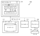
まず、図1Aおよび図1Bを参照して、本発明の一実施形態にかかるホストコンピュータ(情報処理装置)を備える自動レイアウトシステムの構成を説明する。図1Aは自動レイアウトシステム100の構成例を示すブロック図である。また、図1Bは図1Aに示されたホストコンピュータ(情報処理装置)101の構成を更に詳細に示すブロック図である。
1. Configuration Example of Automatic Layout System First, a configuration of an automatic layout system including a host computer (information processing apparatus) according to an embodiment of the present invention will be described with reference to FIGS. 1A and 1B. FIG. 1A is a block diagram illustrating a configuration example of the
本実施形態で説明されるレイアウト編集処理ならびに自動レイアウト処理は、ホストコンピュータ101(汎用コンピュータモジュールで構成される)によって実行される。自動レイアウトシステム100上で実施可能となるレイアウト編集アプリケーションプログラム121はホストコンピュータ101において、そのソフトウェアの全体、あるいは一部分が実行され、これにより、上記レイアウト編集処理ならびに自動レイアウト処理が実現される。
The layout editing process and the automatic layout process described in the present embodiment are executed by the host computer 101 (configured by a general-purpose computer module). The layout
レイアウト編集アプリケーションプログラム121はコンピュータの可読媒体に格納され、そのコンピュータの可読媒体からホストコンピュータ101のメモリ136にロードされ、実行される。そのようなソフトウェアやコンピュータプログラムを格納したコンピュータの可読媒体はコンピュータプログラム製品である。コンピュータにおいてそのコンピュータプログラム製品を使用することにより、ドキュメントの作成や作成されたドキュメントの印刷に好適な装置が提供されることになる。
The layout
図1Bに示されるように、ホストコンピュータ101には、入出力インターフェース143を介してキーボード132や、マウス133のようなポインティングデバイス等が入力装置として接続されている。また、出力装置としてのディスプレイ装置144がビデオインターフェース137を介して接続されている。更に、ローカルプリンタ145等を入出力インターフェース138を介して接続することも可能である。また、入出力インタフェース138はコンピュータモジュール101をネットワーク107へ接続する機能も有する。これにより、ネットワークを介して他のコンピュータ装置にホストコンピュータ101を接続することができる。ネットワーク107の典型的な例としては、ローカルエリアネットワーク(LAN)、あるいはワイドエリアネットワーク(WAN)が挙げられる。
As shown in FIG. 1B, a
また、図1Bに示すように、ホストコンピュータ101は少なくとも1つのプロセッサユニット135、例えば半導体のランダムアクセスメモリ(RAM)やリードオンリーメモリ(ROM)から構成されるメモリユニット136を含んでいる。格納デバイス139は、プログラム等を格納するコンピュータ可読媒体との間でデータのやり取りが可能なハードディスクドライブ140やフロッピー(登録商標)ディスクドライブ141を含む。なお、図1Bには示されていないが、磁気テープドライブ等も格納デバイス139として使用可能である。CD−ROMドライブ142は不揮発性のデータソースとして提供される(もちろん、CD−ROMによってコンピュータプログラムを提供してもよい)。
As shown in FIG. 1B, the
ホストコンピュータ101は、GNU/LINUXやマイクロソフトウインドウズ(登録商標)のようなオペレーティングシステムや、典型的にはオペレーティングシステムに従う形で、あるいは関連のある技術で知られているもので形成されたコンピュータシステムの常套的なオペレーションモードによる方法によって、相互接続バス134を介して通信を行うコンピュータモジュール101のコンポーネント135から143を利用する。すなわち、上述した135〜143で示される各構成は、バス134を介して通信可能に接続されており、ホストコンピュータ101にインストールされたオペレーティングシステムにより利用される。
The
なお、図1Bに示したホストコンピュータ101の例としては、IBM互換PCやSUNのSparcstation、あるいはそれらを含んだコンピュータシステムが考えられる。
As an example of the
本実施形態では、レイアウト編集アプリケーションプログラム121はハードディスクドライブ140に常駐し、プロセッサ135により実行や読み込みがコントロールされるものとする。なお、レイアウト編集アプリケーションプログラム121の媒介記憶装置とネットワーク107からフェッチされるデータはハードディスクドライブ140に呼応して半導体メモリ136を使用する。
In this embodiment, it is assumed that the layout
一つの例では、レイアウト編集アプリケーション121のエンコードされたプログラムは、CD−ROMやフロッピー(登録商標)ディスク上に格納され、対応するドライブ142や141を通じて読み込まれ、ハードディスクドライブ140にインストールされる。あるいは、別の例として、レイアウト編集アプリケーションプログラム121はネットワーク107からホストコンピュータ101内に読み込まれて、ハードディスクドライB140にインストールされてもよい。
In one example, the encoded program of the
さらにソフトウェアは、磁気テープまたはROMまたは集積回路、光磁気ディスク、または、ホストコンピュータ101とその他のデバイス間における赤外線等の無線通信、PCMCIAカードのようなコンピュータ可読カード、そしてEメール通信やWEBサイト上の記録情報を持つインターネットやイントラネットを含む他の適当なコンピュータからホストコンピュータ101内にロードされてもよい。これらは、コンピュータ可読媒体の例であり、他のコンピュータ可読媒体が使用されてもよいことは明らかである。
In addition, the software can be on a magnetic tape or ROM or integrated circuit, a magneto-optical disk, or a wireless communication such as infrared between the
図1Aにおいて、レイアウト編集アプリケーション121はコンピュータに自動レイアウト処理ならびにレイアウト編集処理を行わせるものであり、2つのソフトウェアコンポーネント、すなわちレイアウトエンジン105とユーザインターフェース103とを含んでいる。
In FIG. 1A, a
レイアウトエンジン105は、部分領域であるオブジェクト(矩形の範囲、例えばコンテナ)に与えられたサイズや位置の設定にしたがって、データベース119に格納されているデータから1レコードずつ読み込み、読み込んだデータとオブジェクトの設定とから、読み込んだデータが流し込まれるオブジェクトの大きさや位置等を計算する、自動レイアウト処理を行うソフトウェアコンポーネントである。また、本実施形態では、レイアウトエンジン105は、更に、オブジェクトに割り当てられたデータを描画し、ドキュメントのイメージを生成する処理も行う。ただし、本発明はこれに限るものではなく、レイアウトエンジン105は各部分領域(オブジェクト)のサイズと位置を決定するアプリケーションとして動作し、図示省略したプリンタドライバに描画情報を出力することで、プリンタドライバがドキュメントのイメージ描画処理を行い、印刷データを生成するようにしてもよい。
The
一方、ユーザインタフェース103は、ユーザによるレイアウト編集処理を可能とするもので、具体的には、ユーザはユーザインタフェース103を介してオブジェクトの作成・移動を行い、ドキュメントテンプレートを作成する。また、ドキュメントテンプレート内の各オブジェクトとデータとを関連付けるメカニズムを提供する。さらに、ドキュメントテンプレート内の各オブジェクトに対する各種設定(リンク設定も含む)を可能にする。ユーザインタフェース103とレイアウトエンジン105はコミュニケーションチャネル123を介して通信する。
On the other hand, the
2.他のシステム構成の例
図2は、図1Aと類似のブロック図であるが、エンジンサーバ227が追加されている点が異なる。エンジンサーバ227に格納されているレイアウトエンジン225は、レイアウトエンジン105の分離バージョンである。エンジンサーバ227には一般的なコンピュータが用いられる。レイアウトエンジン225は、印刷やその他の目的に応じてドキュメントを生成するために、ファイルサーバ115に保存されたドキュメントテンプレートとデータベース119に保存されたデータとを結合する。そのようなオペレーションはユーザインタフェース103を介して要求される。
2. Other System Configuration Example FIG. 2 is a block diagram similar to FIG. 1A, except that an
3.レイアウト編集アプリケーションの説明
以下、上記レイアウト編集アプリケーション121のうち、ユーザインターフェース103を介して実現されるレイアウト編集処理の詳細について説明する。
3. Description of Layout Editing Application Hereinafter, details of layout editing processing realized through the
3−1 メインウインドウ
ユーザインターフェース103は、操作時に図3に示されるようなアプリケーションウインドウ301によって形成されたユーザインターフェース画面をビデオディスプレイ144に表示させる。このウインドウ301は、メニューバー302、ツールバー303、ワークエリア306とオプションのパレット311を有する。メニューバー302とツールバー303を非表示にさせたり、スクリーン上の色々な場所に移動させることが可能である。また、ワークエリア306はマウス133の操作によってその場所を移動させることが可能である。また、パレット311はオプションであり、カーソル/ポインタデバイス313はマウス133が指し示す位置を表す。
3-1. Main Window The
メニューバー302は、周知の技術として知られているように、メニューオプションの階層の下に拡張される多くのメニューアイテム304を持つ。
The menu bar 302 has a number of
ツールバー303は、アプリケーションの特別なモードによって非表示状態にする、または表示状態にすることが可能な多くのツールボタンとウィジット305とを持つ。
The
ルーラー308はオプションであり、ワークエリア内のポインタ、ページ、ライン、マージンガイド、オブジェクトの位置を示すために使われる。
パレット311は移動、リサイズ、クローズをするためのウインドウコントロール312を持つ。パレット311はオプションで、ワークエリアの前面に表示される、あるいはオブジェクトの背面に隠される。パレット311はアプリケーションウインドウ301の範囲内のみに表示されるようにすることも、あるいはアプリケーションウインドウ301の外側にその一部或いは全体が表示されるようにすることもできる。
The
ツールバー303には図4に示されるような、ユーザ選択可能な『ボタン』が配置されている。
The
(1)選択ツールボタン403:オブジェクトの辺を選択、移動、サイズ変更、リサイズそしてロック/ロック解除のために使われる。オブジェクトの選択は、オブジェクトの周りに選択ボックスをドラッグすることによりなされる。また、CTRLキーを押しながら、複数のオブジェクトについて選択操作をすることによって、複数のオブジェクトを選択可能である。 (1) Selection tool button 403: used for selecting, moving, resizing, resizing, and locking / unlocking the sides of an object. Selection of an object is done by dragging a selection box around the object. Further, a plurality of objects can be selected by performing a selection operation on the plurality of objects while pressing the CTRL key.
(2)テキストオブジェクトツールボタン404:スタティックあるいはバリアブルテキストを持つオブジェクトを作成するために使われる。 (2) Text object tool button 404: used to create an object having static or variable text.
(3)イメージオブジェクトツールボタン405:スタティックあるいはバリアブルイメージを持つオブジェクトを作成するために使われる。 (3) Image object tool button 405: used to create an object having a static or variable image.
(4)リンクツールボタン406:オブジェクト間に関連付けを行うリンクを作成するために使われ、リンクの距離をコントロールするためにも使われる。 (4) Link tool button 406: used to create a link for associating objects, and also used to control the distance of the link.
3−2 ドキュメントテンプレート
図3において、ワークエリア306はドキュメントテンプレートのデザインを表示・編集するために使われる。これにより、ユーザは下準備で印刷されたドキュメントの概観をデザインすることが可能となる。
3-2 Document Template In FIG. 3, a
ワークエリア306はスクロールバー307とオプションのルーラー308とドキュメントテンプレート309とを備える。ドキュメントテンプレート309はページが複数あることを示すことができる。
The
与えられたドキュメントテンプレートのページサイズは、ユーザによって指定される。それぞれのドキュメントでの実際のページ数は、流し込まれるデータのデータ量によって変化し、1ページ内にフィットできなかった時、追加のページは自動的に作成される。 The page size of a given document template is specified by the user. The actual number of pages in each document varies depending on the amount of data to be inserted, and additional pages are automatically created when it cannot fit within one page.
それぞれのページ内の境界線310は、ページ上の印刷可能なオブジェクトの最大幅を示す、任意のページマージンである。 A border 310 within each page is an arbitrary page margin that indicates the maximum width of a printable object on the page.
また、図4は1ページのドキュメントテンプレート309上に表示することが可能なオブジェクトの例である、それらは、複数のオブジェクト407、408と、任意に適用するアンカーアイコン409とリンク412、そしてスライダー413を持つ。
FIG. 4 is an example of objects that can be displayed on a one-
3−3 オブジェクト
ここで、オブジェクトについて説明する。オブジェクトとは、ドキュメントテンプレート内にデータファイルから固定あるいは可変のテキスト/イメージが流し込まれ、描画されるスペース(これを部分領域と呼ぶ)であり、図4に示されるように他のオブジェクトと共にドキュメントテンプレート内に配置される。ユーザインターフェース画面を介して、ユーザからの操作指示により、オブジェクトはマウス133の操作により移動、サイズ調整、再作成される。下記は本実施形態におけるオブジェクトの定義である。
3-3 Objects Here, objects will be described. An object is a space (this is called a partial area) in which fixed or variable text / image is poured from a data file into a document template and is drawn. As shown in FIG. 4, the document template is combined with other objects. Placed inside. The object is moved, adjusted in size, and recreated by operating the
(1)オブジェクトは固定あるいは可変のコンテンツを持つ。可変コンテンツは、データソースから取得したデータがドキュメント毎、つまりレコード毎に異なる可能性があるという意味でダイナミック(動的)であるということができる。ただし、本実施形態の可変コンテンツは、アニメーション化されたもの、あるいは他の方法で時間的に変化するコンテンツは意図していない。同様に、固定コンテンツはオブジェクトを使って生成される全てのドキュメントで、同じように表示される。しかしながら、可変コンテンツとリンクが設定されている場合、可変コンテンツの影響を受けて、固定コンテンツはそれぞれのドキュメントで位置が異なる可能性がある。 (1) An object has fixed or variable content. The variable content can be said to be dynamic in the sense that the data acquired from the data source may be different for each document, that is, for each record. However, the variable content of the present embodiment is not intended to be animated or content that changes with time in another way. Similarly, fixed content is displayed in the same way in all documents generated using the object. However, when the variable content and the link are set, the position of the fixed content may be different in each document due to the influence of the variable content.
(2)オブジェクトは、コンテンツに適用される背景色、ボーダー、フォント・スタイルのようなテキスト設定と同様の装飾機能を持っている。このような設定をオブジェクト属性と呼ぶ。オブジェクト属性は、各オブジェクトごとに設定可能であるが、あるオブジェクトと同じオブジェクト属性であるという設定を行うことも可能である。 (2) The object has a decoration function similar to the text setting such as the background color, border, font style applied to the content. Such a setting is called an object attribute. Although the object attribute can be set for each object, it can be set that the object attribute is the same as that of a certain object.
(3)オブジェクトはドキュメントを生成する際にデータソースからのデータとマージされる。装飾機能は、どのような固定コンテンツでもそうであるように、印刷された出力物において可視である。可変コンテンツはデータソースからの特定のデータの表示を提供する。オブジェクトのこの表現は例えば印刷されるか、ビデオディスプレイ144のスクリーン上に表示されるか、あるいはその両方が可能である。
(3) The object is merged with data from the data source when generating the document. The decoration function is visible in the printed output, as is any fixed content. Variable content provides an indication of specific data from a data source. This representation of the object can be printed, displayed on the screen of the
(4)オブジェクトは、図4に示されるように視覚的な手がかりとしてのユーザインターフェースを有している。例えばオブジェクトの編集そして表示設定のためのインタラクティブなグラフィカルユーザインターフェース(GUI)を持つ。GUIの各要素はビデオディスプレイ144のスクリーン上に表示されるが、ドキュメントとしては印刷されない。レイアウト編集アプリケーション121のユーザインターフェース103は、背景色やフォントのようなオブジェクトの装飾機能のいくつかを表示し、さらにオブジェクトの設定の編集や表示を可能にするための機能を有している。
(4) The object has a user interface as a visual clue as shown in FIG. For example, it has an interactive graphical user interface (GUI) for object editing and display settings. Each element of the GUI is displayed on the screen of the
ユーザはオブジェクトのサイズ・位置を指定することが可能である。オブジェクトはそれぞれのドキュメントで表示されるコンテンツをどのように結びつけるかの制御に関する制約(制御条件)がある。これらの制約(固定/可変コンテンツをオブジェクトと結びつけることを含む)は、ユーザが一つのドキュメントテンプレートから多数のドキュメントをコントロールする主要な方法である。 The user can specify the size and position of the object. An object has a restriction (control condition) regarding control of how to display contents displayed in each document. These constraints (including linking fixed / variable content with objects) are the primary way a user can control multiple documents from a single document template.
1つのオブジェクトの辺は、関連付けられたコンテンツがドキュメント内で表示される仮想の境界線を定義する。したがって、オブジェクトの左辺を論じることは、関連付けられたコンテンツが、各ドキュメントにおいて、表示可能であるエリア内の最も左の辺を論じることと同じである。同様に、オブジェクトの高さを論じることは、生成されたドキュメントで関連付けられたコンテンツの高さの制約を論じることとして理解される。本明細書では、ユーザインターフェース103を参照してオブジェクトの辺あるいは大きさを論じるところで、この区別は明らかにされるであろう。
A side of one object defines a virtual border where the associated content is displayed in the document. Thus, discussing the left side of an object is the same as discussing the leftmost side in the area where the associated content is displayable in each document. Similarly, discussing the height of an object is understood as discussing content height constraints associated with the generated document. In the present specification, this distinction will be clarified when discussing the side or size of an object with reference to the
3−4 新規オブジェクトの作成方法
図4で示されるように、新規のテキストオブジェクトあるいはイメージオブジェクトは、テキストオブジェクトツール404あるいはイメージオブジェクトツール405をマウス133でクリックし、ドキュメントテンプレート309上に四角形をドラッグすることによって、当該ドキュメントテンプレート309上に作成される。
3-4 Method for Creating New Object As shown in FIG. 4, for a new text object or image object, click the
あるいは、オブジェクトは、適切なツール404、405をアクティブにした後に、ドキュメントテンプレート309上で単にクリックすることによって作成されるようにしてもよい。この場合、マウス133のクリック操作に応じてデフォルトサイズのオブジェクトがテンプレート上に挿入されるとともに、当該新規オブジェクトの寸法等を設定するためのダイアログボックスあるいは他のプロンプトが提供される。なお、オブジェクトのサイズは自動的に前もって定義されるようにしてもよいし、あるいは、計算されたスキーマによって作成・配置されるようにしてもよく、種々の方法が考えられる。ここで生成されたオブジェクトをマウス等の入力装置により選択し、右クリックでプロパティを指示する等の操作を行うことにより、オブジェクトのプロパティダイアログが表示され、オブジェクトの制約を設定することができる。オブジェクトのプロパティダイアログUIでは、上述した各種の制約を設定することができる。また、オブジェクトのプロパティダイアログでは、オブジェクトのサイズ(幅、高さ)や位置を決定することができ、可変サイズにする場合は、オブジェクトの基本パターン(基本サイズと基準位置)を設定し、更に、最大オブジェクトサイズ(幅、高さ)と最小オブジェクトサイズ(幅、高さ)を設定することが可能となっている。
Alternatively, the object may be created by simply clicking on the
3−5 オブジェクトの表示方法
アプリケーション121において、オブジェクトの辺は塗りつぶし線(414)で表示される(ただし、他の方法で辺を示しても良い)。また、アンカー409(辺の近くに描画された線、形状、アイコン)、ハンドル411(辺の移動、修正のために描画されたコントロール点)、スライダー413(辺の両サイドに描画された短い並行線)を備える。
3-5 Object Display Method In the
これらのアイコン・辺のいくつかあるいは全ては、どのツール、どのオブジェクトを選択・ハイライトあるいはアクティブにするかによって、描画されたりされなかったりする。一般的に、オブジェクトの辺・アイコンはドキュメントテンプレートのデザインの手助けであるため、印刷物には描画されない。 Some or all of these icons and edges may or may not be drawn depending on which tool, which object is selected, highlighted or activated. In general, the sides and icons of an object are not drawn on a printed matter because they help to design a document template.
3−6 リンク
リンクは、オブジェクトとオブジェクトの関連を示している。関連とはオブジェクト間の距離を示しており、リンクによって関連付けられたオブジェクト同士は、互いのレイアウト変更の影響を受けてレイアウトを計算する。図4の412で示されているものがリンクであり、この図ではオブジェクト407と408とを関連づけている。
3-6 Link A link indicates the relationship between objects. The relationship indicates the distance between objects, and the objects related by the link are affected by the mutual layout change and the layout is calculated. What is indicated by 412 in FIG. 4 is a link. In this figure, objects 407 and 408 are associated with each other.
3−7 リンクの設定方法
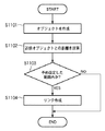
次に、オブジェクト同士を関連付けるためのリンクの設定方法について説明する。図6はリンクの設定方法を示したフローチャートである。また図7(A)乃至(C)はリンク設定の際のUIの一例を示す図である。図6、7を用いてオブジェクトにリンクを設定する方法について説明する。
3-7 Link Setting Method Next, a link setting method for associating objects will be described. FIG. 6 is a flowchart showing a link setting method. FIGS. 7A to 7C are diagrams illustrating an example of a UI at the time of link setting. A method for setting a link to an object will be described with reference to FIGS.
まず、リンクを設定するためには、リンクを設定するためのオブジェクト(最低2つ)を作成する(ステップS601)。図7(A)は、作成された2つのオブジェクト(701、702)を示す。なお、703、704はアンカーを、705はマウスポインタをそれぞれ示している。
First, in order to set a link, an object (at least two) for setting a link is created (step S601). FIG. 7A shows two created objects (701, 702).
ステップS602では、リンクツールボタン406を選択した状態にし、ステップS603では、リンクを設定する片方のオブジェクト(ここでは、オブジェクト701)をマウスポインタ705でクリックして選択する。
In step S602, the
ステップS604では、ステップS603にて選択されたオブジェクト701との間でリンク設定しようとするオブジェクト702を選択する。具体的にはマウスポインタ705を移動して、オブジェクト702をクリックする。図7(B)は、オブジェクト701をクリックした後、オブジェクト702をクリックするまでの間の状態を示す図である。同図に示すように、ステップS603でクリックした位置と、現在のマウスポインタ705の位置との間を結んだ線706が表示される。
In step S604, an
ステップS604において、オブジェクト702が選択されるとオブジェクト701との間にリンクが表示される。図7(C)は、オブジェクト702がクリックされることにより、リンク707が表示された状態を示している。
In step S604, when the
3−8 長さが可変のリンクの設定
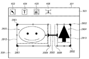
図28では可変リンクの設定のためのUIを表している。図28の状態では、ドキュメントテンプレート309上にコンテナ2803とコンテナ2804が存在する。それぞれのコンテナはアンカーアイコン2801、アンカーアイコン2802と固定された辺2805、辺2806を含んで構成されている。コンテナ2803と2804の間には可変サイズのリンク2809があり、コンテナ2803とコンテナ2804を結んでいる。コンテナ2803とコンテナ2804の間にはリンクが設定されているのでそれぞれの右辺2807と左辺2808は点線で表現されている。このため各コンテナにインジケータ2810、インジケータ2811が表示され、それぞれ辺2807と辺2808が可変であることを示している。
3-8 Link Setting with Variable Length FIG. 28 shows a UI for setting a variable link. In the state of FIG. 28, a
また、図29は、リンク設定手段におけるUI画面であり、リンク2809の情報をセットするためのダイアログウインドウ2901の例である。このダイアログは、タイトルバー2902、ツールボタン2903、ダイアログウインドウの開閉を行うボタン2904、各種の情報をセットするエリア2909で構成されている。このダイアログウインドウではリンクタイプが可変長(2907)のリンクであるか、あるいは固定長(2906)のリンクであるかの択一的な選択を行える。リンクタイプが可変の場合にはリンクの長さの最小値(Min.Distance2910)、最大値(Max.Distance2912)、ならびに基準値(Distance2911)が設定できる。この設定は2つのコンテナ間にリンクを設定した後に、この設定されたリンクをクリック等の操作によって選択したときに表示される。あるいは、リンクを設定した直後に、当該リンクに関するダイアログウインドウ2901が自動的に表示されるようにしてもよい。ここで各コンテナ間の距離の基準値2911は、データを流し込んだ際に各コンテナのサイズが変更されない場合に用いられるリンクの長さである。
FIG. 29 is an example of a
図30は固定サイズのリンクを使用した場合のレイアウト結果を示している。レイアウト計算方法は前述したとおりに従って行われる。例えば図28においてコンテナ2803とコンテナ2804にそれぞれ違ったサイズのイメージデータが挿入された場合を考える。この場合、それぞれのコンテナはデータの大きさを最適とみなし、コンテナ2803は挿入されたイメージサイズになる枠3004(最適コンテナサイズ)に近づこうと右方向へ、同様にコンテナ2804は挿入されたイメージサイズになる枠3005(最適コンテナサイズ)に近づこうと左方向へサイズを変更しようとする。しかしコンテナ2803とコンテナ2804はアンカー2801とアンカー2802によってそれぞれ左辺2812と右辺2813の移動ができず、上記のようにサイズを変更しようとすると両者の間隔を狭めるしかない。しかしながら、コンテナ間には固定サイズのリンク3003が設定されており、レイアウト計算時にその長さ維持されるため、コンテナ2803とコンテナ2804のサイズが変更されることになる。
FIG. 30 shows a layout result when a fixed-size link is used. The layout calculation method is performed as described above. For example, consider a case in which image data of different sizes are inserted into the
その結果、コンテナ2803とコンテナ2804はデータの縦横比に合わせた最適なサイズを確保することが出来ず、最終的に図30に示すように、最適なサイズ(枠3004、枠3005)よりも小さくなってしまう。すなわちリンク3003のサイズが固定であるためコンテナ2803とコンテナ2804は最適サイズを達成できない(図30において、各コンテナ内の一点差線で示した範囲がデータの持つ縦横比である)。
As a result, the
一方、図31は図30と同様の状態でリンクを可変サイズにした場合を示している。この場合、上記の例でコンテナ2803とコンテナ2804の間には図示の通り可変サイズのリンクが設定されている。したがって、コンテナ2803とコンテナ2804のサイズが変更される際には、リンクサイズが縮まることでコンテナ2803とコンテナ2804のサイズを図30の例より大きくすることができる。この結果、挿入されるデータサイズに合わせた最適なサイズを達成できる、あるいはより挿入データサイズ(最適サイズ)に近いコンテナの枠を設定することが出来る。図31はこの結果を示しており、可変リンク2809はレイアウト計算の結果、可変リンク3103に示されるようなサイズ状態となる。なお、この場合コンテナ2803とコンテナ2804はそれぞれ最適なサイズ(データサイズに合った大きさ)になっている。
On the other hand, FIG. 31 shows a case where the link is made variable in the same state as FIG. In this case, in the above example, a variable-size link is set between the
4.自動リンク機能の説明
次に本実施形態にかかるホストコンピュータ101の備えるレイアウト編集アプリケーション121の特徴的な機能である、自動リンク機能について説明する。本実施形態にかかるホストコンピュータ101は、オブジェクト間のリンク設定をユーザが手動で行う機能(上記3−6)に加え、さらに、自動でリンク設定を行う機能を備えている。自動リンク機能に関してはメニューバーにあるファイルや表示メニューより自動リンク機能のUIを表示させ、自動リンクを行うことを設定する。なお、自動リンク機能を用いる場合には、リンクの詳細について設定することができるが、それらについては図8で後述する。以下、当該自動リンク機能の詳細について説明する。
4). Description of Automatic Link Function Next, the automatic link function, which is a characteristic function of the
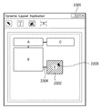
4−1 自動リンク機能を用いてレイアウト編集処理を行うためのウィンドウ
図5は、自動リンク機能を備えるレイアウト編集アプリケーション121を用いてレイアウト編集処理を行う場合に表示されるユーザインターフェースの一例を示す図である。同図において、501はアプリケーションウインドウ、502はオブジェクト、503はオブジェクト間に設定されているリンク、504はマウスポインタを示している。
4-1 Window for Performing Layout Editing Process Using Automatic Link Function FIG. 5 is a diagram showing an example of a user interface displayed when performing a layout editing process using the
なお、本明細書中にオブジェクトの位置についての記述があるが、オブジェクトの位置は、ドキュメント内左上を原点として、水平方向をX方向、垂直方向をY方向と定義する。なお、自動リンク機能を実行するにあたっては、オブジェクトは可変であることが前提であり、アンカー設定がされている等オブジェクトが固定である場合には、自動リンク機能は動作しない。 Although there is a description about the position of the object in this specification, the position of the object is defined as the X direction in the horizontal direction and the Y direction in the vertical direction with the upper left corner in the document as the origin. In executing the automatic link function, it is assumed that the object is variable, and the automatic link function does not operate when the object is fixed, for example, an anchor is set.
4−2 設定ウィンドウ
図8は自動リンク機能を動作させるにあたり、オブジェクト間の距離を設定するためのダイアログウィンドウ801の一例を示す図である。同図に示すようにダイアログウィンドウ801はタイトルバー802、ツールボタン803、ダイアログウィンドウの開閉を行うボタン804、オブジェクト間の距離情報を設定する設定欄807を備える。
4-2 Setting Window FIG. 8 is a diagram showing an example of a
ユーザは、ダイアログウィンドウ801において、リンクを自動的に作成するオブジェクト間の距離806を設定する(以下、806を「設定距離」と称す)。また自動的に作成するリンクの長さであるLink Length808を指定することも可能である。Link Length808を指定しない場合、設定されるリンクの長さはオブジェクト間の距離となる。ダイアログウィンドウ開閉ボタン804のOKボタンを押圧することで設定を適用すると、ダイアログウィンドウ801の設定情報はメモリ136に格納される。なお、図8で設定するリンクの種類は固定リンクの生成を想定しているが、ここでリンクの種類として固定リンクまたは可変リンクを選択できるようにしても構わない。また、ここで可変リンクの設定が選択された場合、図29の可変リンクの設定UIが表示されることとなる。
The user sets a
4−3 新規にオブジェクトを作成した場合の自動リンク機能の動作
図11はオブジェクトを新規作成した場合の自動リンク機能の全体の処理の流れを示すフローチャートである。なお、図11の処理は、ホストコンピュータ101内のプロセッサ135が制御することによって実現される。
4-3 Operation of Automatic Link Function when New Object is Created FIG. 11 is a flowchart showing the overall processing flow of the automatic link function when a new object is created. Note that the processing in FIG. 11 is realized by the control of the
ステップS1101で、ユーザがテキストオブジェクトツール404、あるいはイメージオブジェクトツール405を用いて新規にオブジェクトを作成すると、レイアウト編集アプリケーション121は作成されたオブジェクトの位置情報をメモリ136に格納する。
When the user creates a new object using the
ステップS1102において、レイアウト編集アプリケーション121は、作成したオブジェクトとその近傍にあるオブジェクトとの距離を計算する。なお、本明細書において、オブジェクト間の距離とは対象となるオブジェクト間の最も近い辺同士の距離をいう。近傍に複数のオブジェクトが存在する場合にはそれぞれについて距離を求める。
In step S1102, the
ステップS1103において、レイアウト編集アプリケーション121は、得られた距離と予め設定された設定距離806とを比較し、得られた距離が設定距離以下であった場合には該オブジェクト間にリンクを作成し(ステップS1104)、処理を終了する。一方、得られた距離が設定距離より大きい場合には、リンク作成を行うことなく処理を終了する。なお、リンク作成処理の詳細は後述するものとする。
In step S1103, the
4−4 オブジェクトを移動させた場合の自動リンク機能の動作
図12はレイアウトされたオブジェクトを移動させた場合の自動リンク機能の全体の処理の流れを示すフローチャートである。なお、図12の処理は、ホストコンピュータ101内のプロセッサ135が制御することによって実現される。
4-4 Operation of Automatic Link Function when Moving Object FIG. 12 is a flowchart showing the overall processing flow of the automatic link function when moving a layout object. Note that the processing in FIG. 12 is realized by the control of the
ステップS1201で、ユーザが移動させるオブジェクトを選択すると、レイアウト編集アプリケーション121は、ユーザによって選択された当該オブジェクトを認識する。
When the user selects an object to be moved in step S1201, the
ステップS1202では、当該認識したオブジェクトをユーザに視覚的に示すためにUIを変更する。図9はオブジェクトEが選択されたことを示している。マウスポインタ903で矩形902をドラッグして矩形内にオブジェクトを入れることによって選択することが可能である。また、マウスポインタ903でオブジェクトを押下することによって選択することもできる。なお、選択方法は特にこれらの方法に限定されるものではなく、他の方法であっても良い。図10は、前記オブジェクトEが選択されたことをユーザに明示するためにオブジェクトEの表示が変更された例を示している(1002)。なお、この例ではオブジェクトに斜線を入れてあるが、他の方法で選択されたことを示しても良い。
In step S1202, the UI is changed to visually show the recognized object to the user. FIG. 9 shows that the object E has been selected. It is possible to select by dragging the
ステップS1203で、ユーザが選択されたオブジェクトをマウス133でドラッグし所望の位置に移動させると、レイアウトエンジン105は移動した先のオブジェクトの位置情報を取得する。図13は選択されたオブジェクトEをマウスポインタ1303でドラッグすることにより移動させている様子を示している(1302)。
In step S1203, when the user drags the selected object with the
ここで、移動させたオブジェクトがマウス133によってドラッグされたままの状態にあると、オブジェクトの新規作成の場合と同様に、アプリケーション121は近傍にあるオブジェクトとの距離を計算する(ステップS1204)。近傍に複数のオブジェクトが存在する場合にはそれぞれについて距離を求める。
If the moved object remains dragged by the
ステップS1205において、レイアウト編集アプリケーション121は、得られた距離と設定距離806を比較し、得られた距離が設定距離以下であった場合には、ステップS1206に進み、ユーザに視覚的に示すためのUIを表示する。図14は、前記移動させたオブジェクトが設定距離以下であることをユーザに示すためのUIの例を示している(1402)。この例では、リンクを点線で示しているが、他の方法で示すようにしてもよい。
In step S1205, the
ステップS1207では、前記UI1402が表示された状態でユーザがマウス133をドロップすると、レイアウト編集アプリケーション121はオブジェクトの選択が解除されたものと認識し、ステップS1208にて、該オブジェクト間にリンクを作成する。図19は図14の状態からマウスをドロップし、リンクのUIを通常の表示1902に変更してオブジェクト間にリンクが作成されたことを示している。このとき、選択したオブジェクトのメモリ136上の位置情報が、移動した位置に更新される。
In step S1207, when the user drops the
一方、マウス133をドロップせずにさらに移動させると、レイアウト編集アプリケーション121は再度近傍オブジェクトとの距離を計算する(つまり、ステップS1207において「No」となり、ステップS1204に戻る)。
On the other hand, when the
4−5 リンク作成処理(オブジェクトを新規作成した場合)
図15はオブジェクト新規作成時のリンク作成処理(ステップS1104)の詳細を示すフローチャートである。なお、図15の処理は、ホストコンピュータ101内のプロセッサ135が制御することによって実現される。
4-5 Link creation process (when a new object is created)
FIG. 15 is a flowchart showing details of the link creation processing (step S1104) when creating a new object. Note that the processing in FIG. 15 is realized by the control of the
ステップS1501において、レイアウトエンジン105はまず、新規作成したオブジェクトの位置情報を取得する。前述したように、本明細書においてオブジェクト間の距離は、オブジェクト間における辺同士の距離を用いるため、「取得する位置情報」とはオブジェクトの各辺のX方向およびY方向の位置情報である。
In step S1501, the
次に、ステップS1502において、レイアウト編集アプリケーション121は前記オブジェクト以外にレイアウトされているオブジェクトがあるか確認する。前記オブジェクト以外にレイアウトされているオブジェクトがあった場合、レイアウト編集アプリケーション121はその個数および各位置情報を取得する。なお、取得した各オブジェクトの位置情報は配列に格納される。
Next, in step S1502, the
次に、ステップS1503において、レイアウト編集アプリケーション121はリンク設定の処理を行う。リンク設定の処理が終了し、他にレイアウトされているオブジェクトがない場合、処理は終了する。
In step S1503, the
4−6 リンク設定処理(オブジェクトを新規作成した場合)
図16A、16Bは図15のリンク設定処理(ステップS1503)の詳細な処理の流れを示すフローチャートである。なお、図16Aおよび図16Bの処理は、ホストコンピュータ101内のプロセッサ135が制御することによって実現される。リンクの設定は、近傍にあるオブジェクトを抽出し、そのオブジェクト間のリンクを設定する。オブジェクト間の距離が前記設定距離以下となった場合にオブジェクト間にリンクを設定し、前記設定距離以下となるオブジェクトが複数見つかった場合は、それぞれ設定距離以下である複数のコンテナに対してリンクを設定する。
4-6 Link setting process (when a new object is created)
16A and 16B are flowcharts showing the detailed processing flow of the link setting processing (step S1503) in FIG. 16A and 16B is realized by the control of the
ステップS1601において、レイアウト編集アプリケーション121はリンクを自動的に作成するオブジェクト間の距離806をDist_AutoLinkに代入する。次に、iに1を代入する。
In step S1601, the
ステップS1602では、作成したオブジェクトとi番目のオブジェクトのY方向の位置が重なるかどうかをチェックする。本実施形態にかかる自動リンク機能では、作成されるリンクは、オブジェクト同士が同じ水平方向または垂直方向にあるということを前提にしている。図18はリンク作成の対象となる領域を示している。作成したオブジェクト1801のX方向の辺の延長線1807とY方向の辺で囲まれた領域1808、1811、およびY方向の辺の延長線1806とX方向の辺で囲まれた領域1809、1810内にオブジェクトの一部あるいは全部が存在する場合にリンク作成の対象となる。このとき、オブジェクト1801のX方向の辺の延長線1807やY方向の辺の延長線1806と他のオブジェクトのリンクは作成されない。図18では、オブジェクト1801とX方向のリンク対象となるのはオブジェクト1803、Y方向のリンクの対象となるのはオブジェクト1802、1805であり、オブジェクト1804はリンク設定の対象外である。
In step S1602, it is checked whether the created object and the i-th object overlap in the Y direction. In the automatic link function according to the present embodiment, the created link is based on the premise that the objects are in the same horizontal direction or vertical direction. FIG. 18 shows an area for which a link is created. In the created
ステップS1602で重なると判断された場合には、ステップS1603に進み、X方向の位置が重なるかどうかをチェックする。X方向の位置が重ならないと判断された場合には、ステップS1614に進む。 If it is determined in step S1602 that they overlap, the process advances to step S1603 to check whether the positions in the X direction overlap. If it is determined that the positions in the X direction do not overlap, the process proceeds to step S1614.
ステップS1614では、i番目のオブジェクトのX方向の辺のうち作成したオブジェクトに近い方の辺にアンカー設定がされているかどうかチェックする。辺にアンカー設定がされている場合には、その辺は固定であるためリンク設定は行わない。アンカー設定がされていなければ、ステップS1604に進み、作成したオブジェクトとi番目のオブジェクトのX方向の辺のうち近い辺同士の差を計算して、結果をDistXに代入する。 In step S1614, it is checked whether an anchor is set on the side closer to the created object among the sides in the X direction of the i-th object. If an anchor is set for a side, the link is not set because the side is fixed. If the anchor is not set, the process advances to step S1604 to calculate the difference between the sides in the X direction of the created object and the i-th object and substitute the result into DistX.
ステップS1605において、レイアウト編集アプリケーション121は、ステップS1604で計算されたDistXと自動リンクを作成する設定距離が格納されているDist_AutoLinkとを比較する。もし、DistXがDist_AutoLinkよりも小さければ、すなわち、計算されたDistXの値が設定距離以下であると判定された場合、ステップS1606に進み、該オブジェクト間にX方向のリンクを作成する。
In step S1605, the
一方、ステップS1603で重なると判断された場合とは、オブジェクト同士が重なっていることを意味している。図20はオブジェクト2001に重なる位置にオブジェクト2003を作成した例を示している。この場合、ステップS1607にて、レイアウト編集アプリケーション121はユーザに対してリンクを設定するかどうかの確認を行う(詳細は後述)。
On the other hand, the case where it is determined in step S1603 that the objects overlap each other means that the objects overlap each other. FIG. 20 shows an example in which an
ステップS1606及びS1607を処理した後や、ステップS1614で辺にアンカーが設定されている場合、あるいはステップS1605でDistXがDist_AutoLinkよりも大きいと判断された場合には、ステップS1608に進み、次の近傍オブジェクトをチェックするためにiをインクリメントする。 After processing steps S1606 and S1607, when an anchor is set on the edge in step S1614, or when it is determined in step S1605 that DistX is greater than Dist_AutoLink, the process proceeds to step S1608 and the next neighboring object Increment i to check.
以上はX方向のリンクの作成についての処理であるが、ステップS1602で重ならないと判断された場合には、図16BのステップS1610に進み、レイアウト編集アプリケーション121はY方向のリンクについてチェックを行い、オブジェクト同士がX方向に重なるかを判断する。
The above is the process for creating the link in the X direction. If it is determined in step S1602 that the links do not overlap, the process proceeds to step S1610 in FIG. 16B, and the
ステップS1610にて重なると判断された場合には、ステップS1615に進み、i番目のオブジェクトのY方向の辺のうち作成したオブジェクトに近い方の辺にアンカー設定がされているかどうかチェックする。アンカー設定がされていなければ、ステップS1611に進み、レイアウト編集アプリケーション121は作成したオブジェクトとi番目のオブジェクトのY方向の辺のうち近い辺同士の差を計算して、結果をDistYに代入する。
If it is determined in step S1610 that they overlap, the process proceeds to step S1615, and it is checked whether an anchor is set on the side closer to the created object among the Y-direction sides of the i-th object. If the anchor is not set, the process advances to step S1611, and the
さらにステップS1612では、ステップS1611で計算されたDistYとDist_AutoLinkとを比較する。もし、DistYがDist_AutoLinkよりも小さければ、すなわち、計算されたDistXの値が設定距離以下であると判定された場合、ステップS1613に進み、該オブジェクト間にY方向のリンクを作成する。 In step S1612, DistY calculated in step S1611 is compared with Dist_AutoLink. If DistY is smaller than Dist_AutoLink, that is, if it is determined that the calculated value of DistX is equal to or less than the set distance, the process proceeds to step S1613 to create a link in the Y direction between the objects.
ステップS1613を処理した後や、ステップS1610で重ならないと判断された場合、あるいはステップS1615で辺にアンカーが設定されている場合、あるいはステップ1612でDistYがDist_AutoLinkよりも大きいと判断された場合には、ステップS1608に進み、レイアウト編集アプリケーション121は次の近傍オブジェクトをチェックするためにiをインクリメントする。
After processing step S1613, if it is determined in step S1610 that they do not overlap, if an anchor is set on the side in step S1615, or if it is determined in step 1612 that DistY is greater than Dist_AutoLink In step S1608, the
ステップS1609では、配置されているオブジェクトすべてについてチェックを行ったかどうかを判断し、まだ行っていなければ、ステップS1602へ進み処理を繰り返す。全てについてチェックが終了した場合にはリンク設定処理を終了する。このように、オブジェクトを新たに作成した時点でユーザが設定した所定距離内に他のオブジェトが存在することが確認されれば、自動的にリンクが作成されるので、オブジェクトが増加してもユーザの作業効率の低下にはならない。 In step S1609, it is determined whether or not all the arranged objects have been checked. If not, the process proceeds to step S1602 and the process is repeated. When all the checks are completed, the link setting process is terminated. In this way, if it is confirmed that another object exists within a predetermined distance set by the user when the object is newly created, a link is automatically created. The work efficiency is not reduced.
4−7 リンク作成処理(オブジェクトを移動させた場合)
図21はオブジェクト移動時のリンク作成処理(ステップS1208)の詳細を示すフローチャートである。なお、図21の処理は、ホストコンピュータ101内のプロセッサ135が制御することによって実現される。
4-7 Link creation process (when an object is moved)
FIG. 21 is a flowchart showing details of the link creation processing (step S1208) when moving an object. 21 is realized by the control of the
ステップS2101において、レイアウトエンジン105は選択したオブジェクトの位置情報を取得する。次に、ステップS2102において、レイアウト編集アプリケーション121は前記オブジェクト以外に配置されているオブジェクトがあるか確認する。ステップS2102において、他に配置されているオブジェクトがないと判定された場合には、ステップS2108にてオブジェクトを移動させて処理は終了する。
In step S2101, the
一方、ステップS2102において他に配置されているオブジェクトがあると判定された場合には、ステップS2103に進み、アプリケーション121は選択したオブジェクトに自動リンクを行わない属性がついているかを確認する。なお、自動リンクを行わない属性とは、自動リンク機能を無効にする属性で、オブジェクト間の距離が前記設定距離806以下となった場合でもオブジェクト間にリンクを作成しない。
On the other hand, if it is determined in step S2102 that there is another object arranged, the process advances to step S2103, and the
図27は、各オブジェクトに自動リンクを行うかどうかを設定するためのダイアログウィンドウを示す図で、各オブジェクトを選択してマウスの右クリックあるいはキーボードの特定のキーによりプロパティーダイアログウィンドウ2701が表示される。自動リンクを行う設定であるが、自動リンクを行わない属性2705を選択することにより、自動リンク機能を無効化できる。オブジェクトに前記自動リンクを行わない属性がついている場合、他オブジェクトとの間でリンクを作成することなく任意に移動することが可能となる。既に他のオブジェクトとリンクが設定されている場合には、オブジェクトを移動してユーザが指定した所定距離も大きくなったとしてもそのリンクを保持しつつ、それ以上のリンクを作成せずに移動できる。
FIG. 27 is a diagram showing a dialog window for setting whether to automatically link each object. A
図23は、既にリンク2304が設定されているオブジェクト2302が選択されている例を示している。オブジェクト2302に前記自動リンクを行わない属性がつけられている場合に、図23の状態からオブジェクト2302を移動させて図24に示すようにオブジェクト2402、2405の距離が前記設定距離806以下となった場合にも、オブジェクト2402、2405間にリンクは作成されない。またオブジェクト2402、2406間の距離が前記設定距離806より大きくなった場合でもリンク2404は設定されたままとなる。
FIG. 23 shows an example in which an
図21に戻る。ステップS2103で選択したオブジェクトに前記自動リンクを行わない属性がついていない場合には、ステップS2104に進み、レイアウト編集アプリケーション121は他に配置されている各オブジェクトの個数および各位置情報を取得する。なお、取得した各オブジェクトの位置情報は配列に格納される。
Returning to FIG. If the object selected in step S2103 does not have an attribute that does not perform the automatic link, the process advances to step S2104, and the
ステップS2105では、ユーザがオブジェクトを移動させる際に既に設定されているリンクを保持すると選択したか、破棄すると選択したかを判定する。リンクの保持/破棄の選択は、例えばキーボード132の特定のキーを押下しながらオブジェクトを移動させることが考えられる。ただし、この方法に限らず、他の方法で保持/破棄を選択しても良い。
In step S <b> 2105, it is determined whether the user has selected to hold a link that has already been set when moving the object, or has selected to cancel the link. As for selection of link holding / discarding, for example, it is conceivable to move an object while pressing a specific key of the
ステップS2105において、既存リンクの保持が選択されたと判定された場合、既存のリンク情報を保持したままオブジェクトの移動を行い(ステップS2107、S2108)、レイアウト編集アプリケーション121はリンクの作成されていないオブジェクトのみを対象としてリンク作成の処理を行う(ステップS2109)。一方、ステップS2105において既存リンクの破棄が選択されたと判定された場合には、既存のリンク情報を破棄したうえでオブジェクトの移動を行い(ステップS2106、S2108)、レイアウトされた全てのオブジェクトを対象としてリンク作成処理を行う(ステップS2109)。
If it is determined in step S2105 that retention of the existing link has been selected, the object is moved while retaining the existing link information (steps S2107 and S2108), and the
図25は、図23でオブジェクト2302に前記自動リンクを行わない属性がつけられていない場合に、ユーザが既存リンク保持を選択して、オブジェクト2502、2505間の距離が前記設定距離806以下となるようオブジェクト2502を移動させた場合の例を示している。オブジェクト2502、2507間の距離が前記設定距離806より大きくなった場合でもリンク2504は設定されたままである。
FIG. 25 shows that when the
図26は、図23でオブジェクト2302に前記自動リンクを行わない属性がつけられていない場合に、ユーザが既存リンク破棄を選択し、オブジェクト2602、2605間の距離が前記設定距離0806以下となるようオブジェクト2602を移動させた例を示している。オブジェクト2602、2607間の距離が前記設定距離806より大きくなった場合は既に設定されていたリンク2404は解除され、画面からは消去される。前述したように、オブジェクトを移動させた場合はマウスのドロップ時にリンクが作成される(ステップS2110)。
FIG. 26 shows that when the
4−8 リンク設定処理(オブジェクトを移動させた場合)
図22A、22Bは図21のリンク設定処理(ステップS2109)の詳細な処理の流れを示すフローチャートである。なお、図22Aおよび図22Bの処理は、ホストコンピュータ101内のプロセッサ135が制御することによって実現される。各ステップはオブジェクトの新規作成時とほぼ同じ処理である。異なるのは、ステップS2206、S2213での処理が、図21のステップS2110で最終的にリンクを確定するための一時的なリンクを作成するという点である。その他のステップはオブジェクトの新規作成時と同じであるため、ここでは説明を省略する。このようにオブジェクトを移動した結果、他のオブジェクト間の距離が所定距離以下であると判定された場合、自動的にリンクが作成されるのでオブジェクトの編集においてもユーザの作業効率低下を防ぐことができる。
4-8 Link setting process (when an object is moved)
22A and 22B are flowcharts showing the detailed processing flow of the link setting processing (step S2109) of FIG. 22A and 22B is realized by the control of the
4−9 エラー処理
図17はオブジェクトを作成あるいは移動した際に他のオブジェクトと重なった場合(図20の場合)に表示されるダイアログウィンドウ1701の例である。このダイアログウィンドウはリンク作成を行うかをユーザに確認するためのものであり、一般的な処理を継続するボタン1703を選択すればリンクを作成し、処理を中止するボタン1704が選択されればリンクは作成しない。
4-9 Error Processing FIG. 17 shows an example of a
以上の説明から明らかなように、本実施形態にかかる自動レイアウトシステムによれば、レイアウト編集処理において、隣接するオブジェクトが所定の距離以下になると、自動的にリンクを作成するため、従来のように、オブジェクトの数が増えても、リンク設定のための作業負荷が増大することはなくなり、自動レイアウトシステムにおけるユーザの設定作業の効率化を実現することができる。 As is clear from the above description, according to the automatic layout system according to the present embodiment, in the layout editing process, a link is automatically created when an adjacent object is less than a predetermined distance. Even if the number of objects increases, the work load for link setting does not increase, and the efficiency of user setting work in the automatic layout system can be realized.
[他の実施形態]
なお、本発明は、複数の機器(例えばホストコンピュータ、インタフェイス機器、リーダ、プリンタなど)から構成されるシステムに適用しても、一つの機器からなる装置(例えば、複写機、ファクシミリ装置など)に適用してもよい。
[Other Embodiments]
Note that the present invention can be applied to a system including a plurality of devices (for example, a host computer, an interface device, a reader, and a printer), and a device (for example, a copying machine and a facsimile device) including a single device. You may apply to.
また、本発明の目的は、前述した実施形態の機能を実現するソフトウェアのプログラムコードを記録した記憶媒体を、システムあるいは装置に供給し、そのシステムあるいは装置のコンピュータ(またはCPUやMPU)が記憶媒体に格納されたプログラムコードを読出し実行することによっても、達成されることは言うまでもない。 Another object of the present invention is to supply a storage medium storing software program codes for implementing the functions of the above-described embodiments to a system or apparatus, and the computer (or CPU or MPU) of the system or apparatus stores the storage medium. Needless to say, this can also be achieved by reading and executing the program code stored in.
この場合、記憶媒体から読出されたプログラムコード自体が前述した実施形態の機能を実現することになり、そのプログラムコードを記憶した記憶媒体は本発明を構成することになる。 In this case, the program code itself read from the storage medium realizes the functions of the above-described embodiments, and the storage medium storing the program code constitutes the present invention.
プログラムコードを供給するための記憶媒体としては、例えば、フロッピ(登録商標)ディスク、ハードディスク、光ディスク、光磁気ディスク、CD−ROM、CD−R、磁気テープ、不揮発性のメモリカード、ROMなどを用いることができる。 As a storage medium for supplying the program code, for example, a floppy (registered trademark) disk, hard disk, optical disk, magneto-optical disk, CD-ROM, CD-R, magnetic tape, nonvolatile memory card, ROM, or the like is used. be able to.
また、コンピュータが読出したプログラムコードを実行することにより、前述した実施形態の機能が実現されるだけでなく、そのプログラムコードの指示に基づき、コンピュータ上で稼働しているOS(オペレーティングシステム)などが実際の処理の一部または全部を行い、その処理によって前述した実施形態の機能が実現される場合も含まれることは言うまでもない。 Further, by executing the program code read by the computer, not only the functions of the above-described embodiments are realized, but also an OS (operating system) operating on the computer based on the instruction of the program code. It goes without saying that a case where the function of the above-described embodiment is realized by performing part or all of the actual processing and the processing is included.
さらに、記憶媒体から読出されたプログラムコードが、コンピュータに挿入された機能拡張ボードやコンピュータに接続された機能拡張ユニットに備わるメモリに書込まれた後、そのプログラムコードの指示に基づき、その機能拡張ボードや機能拡張ユニットに備わるCPUなどが実際の処理の一部または全部を行い、その処理によって前述した実施形態の機能が実現される場合も含まれることは言うまでもない。 Further, after the program code read from the storage medium is written into a memory provided in a function expansion board inserted into the computer or a function expansion unit connected to the computer, the function expansion is performed based on the instruction of the program code. It goes without saying that the CPU or the like provided in the board or the function expansion unit performs part or all of the actual processing, and the functions of the above-described embodiments are realized by the processing.
101 ホストコンピュータ
103 ユーザインターフェース
105 レイアウトエンジン
119 データベース
121 レイアウト編集アプリケーションプログラム
132 キーボード
133 マウス
143 I/Oインタフェース
144 ビデオディスプレイ
301 アプリケーションウインドウ
303 ツールバー
313 カーソル/ポインタ
406 リンクツールボタン
407、408 オブジェクト
409 アンカーアイコン
412 リンク
101
Claims (21)
前記リンクを作成するためのリンク作成条件として、ユーザからの指示に応じて、前記第1部分矩形領域を構成する辺と、該辺に対向する前記第2部分矩形領域の辺との間の距離を設定する設定工程と、
ユーザからの指示に応じて、作成するリンクの種類として、固定サイズのリンクまたは可変サイズのリンクを設定するリンク設定工程と、
前記ドキュメント上における前記第1部分矩形領域を構成する辺の位置を取得する取得工程と、
前記取得工程において取得された位置に基づいて、前記第1部分矩形領域を構成する辺と、前記ドキュメント上に既に配置されている第2部分矩形領域の、該第1部分矩形領域を構成する辺に対向する辺との間の距離を計算する計算工程と、
前記計算工程において計算された前記距離と前記リンク作成条件とを用いて、前記第1部分矩形領域を構成する辺と、該辺に対向する前記第2部分矩形領域を構成する辺との間に前記リンクを作成すべきか否かを判定する判定工程と、
前記判定工程において、前記リンクを作成すべきと判定された場合に、前記リンク設定工程において設定された種類のリンクを作成するリンク作成工程と
を備えることを特徴とする情報処理方法。 And sides of the first partial rectangular area of the document, between the sides of the second partial rectangular region opposite the 該辺, to create a link, if the data is input to the partial rectangular region The first partial rectangle is defined by defining the position of the side constituting the first partial rectangular area and the position of the side of the second partial rectangular area facing the side according to the created link . An information processing method in an information processing apparatus for determining a layout of an area and the second partial rectangular area ,
As a link creation condition for creating the link , according to an instruction from the user, a distance between a side constituting the first partial rectangular region and a side of the second partial rectangular region facing the side A setting process for setting
In accordance with an instruction from the user, as a type of link to be created, a link setting step for setting a fixed size link or a variable size link,
An acquisition step of acquiring a position of an edge constituting the first partial rectangular area on the document;
Based on the position acquired in the acquisition step, sides forming the sides of the said first partial rectangular region, the second partial rectangular area that is already disposed on the document, the first partial rectangular area A calculation step for calculating the distance between the side opposite to
Using said the calculated the distance and the link creation condition in the calculating step, the sides of the said first partial rectangular area between the sides of the second partial rectangular region facing the該辺 A determination step of determining whether or not to create the link;
A link creation step of creating a link of the type set in the link setting step when it is determined in the determination step that the link should be created.
前記リンクを作成するためのリンク作成条件として、ユーザからの指示に応じて、前記第1部分矩形領域を構成する辺と、該辺に対向する前記第2部分矩形領域の辺との間の距離を設定する設定手段と、
ユーザからの指示に応じて、作成するリンクの種類として、固定サイズのリンクまたは可変サイズのリンクを設定するリンク設定手段と、
前記ドキュメント上における前記第1部分矩形領域を構成する辺の位置を取得する取得手段と、
前記取得手段により取得された位置に基づいて、前記第1部分矩形領域を構成する辺と、前記ドキュメント上に既に配置されている第2部分矩形領域の、該第1部分矩形領域を構成する辺に対向する辺との間の距離を計算する計算手段と、
前記計算手段により計算された前記距離と前記リンク作成条件とを用いて、前記第1部分矩形領域を構成する辺と、該辺に対向する前記第2部分矩形領域を構成する辺との間に前記リンクを作成すべきか否かを判定する判定手段と、
前記判定手段により、前記リンクを作成すべきと判定された場合に、前記リンク設定手段により設定された種類のリンクを作成するリンク作成手段と
を備えることを特徴とする情報処理装置。 And sides of the first partial rectangular area of the document, between the sides of the second partial rectangular region opposite the 該辺, to create a link, if the data is input to the partial rectangular region The first partial rectangle is defined by defining the position of the side constituting the first partial rectangular area and the position of the side of the second partial rectangular area facing the side according to the created link . An information processing apparatus for determining a layout of an area and the second partial rectangular area ,
As a link creation condition for creating the link , according to an instruction from the user, a distance between a side constituting the first partial rectangular region and a side of the second partial rectangular region facing the side A setting means for setting
Link setting means for setting a fixed size link or a variable size link as a type of link to be created according to an instruction from the user,
Obtaining means for obtaining a position of a side constituting the first partial rectangular area on the document;
Based on the obtained position by the acquisition unit, sides forming the sides of the said first partial rectangular region, the second partial rectangular area that is already disposed on the document, the first partial rectangular area A calculating means for calculating a distance between the side opposite to
Using said link creation conditions to the calculated the distance by the calculation means, the sides of the said first partial rectangular area between the sides of the second partial rectangular region facing the該辺 Determining means for determining whether or not to create the link;
An information processing apparatus comprising: a link creating unit that creates a link of a type set by the link setting unit when the determining unit determines that the link should be created.
前記リンクを作成するためのリンク作成条件として、ユーザからの指示に応じて、前記第1部分矩形領域を構成する辺と、該辺に対向する前記第2部分矩形領域の辺との間の距離を設定する設定工程と、
ユーザからの指示に応じて、作成するリンクの種類として、固定サイズのリンクまたは可変サイズのリンクを設定するリンク設定工程と、
前記ドキュメント上における前記第1部分矩形領域を構成する辺の位置を取得する取得工程と、
前記取得工程において取得された位置に基づいて、前記第1部分矩形領域を構成する辺と、前記ドキュメント上に既に配置されている第2部分矩形領域の、該第1部分矩形領域を構成する辺に対向する辺との間の距離を計算する計算工程と、
前記計算工程において計算された前記距離と前記リンク作成条件とを用いて、前記第1部分矩形領域を構成する辺と、該辺に対向する前記第2部分矩形領域を構成する辺との間に前記リンクを作成すべきか否かを判定する判定工程と、
前記判定工程において、前記リンクを作成すべきと判定された場合に、前記リンク設定工程において設定された種類のリンクを作成するリンク作成工程と
を前記コンピュータに実行させることを特徴とするプログラム。 And sides of the first partial rectangular area of the document, between the sides of the second partial rectangular region opposite the 該辺, to create a link, if the data is input to the partial rectangular region The first partial rectangle is defined by defining the position of the side constituting the first partial rectangular area and the position of the side of the second partial rectangular area facing the side according to the created link . A program for causing a computer to execute an information processing method for determining a layout of an area and the second partial rectangular area ,
As a link creation condition for creating the link , according to an instruction from the user, a distance between a side constituting the first partial rectangular region and a side of the second partial rectangular region facing the side A setting process for setting
In accordance with an instruction from the user, as a type of link to be created, a link setting step for setting a fixed size link or a variable size link,
An acquisition step of acquiring a position of an edge constituting the first partial rectangular area on the document;
Based on the position acquired in the acquisition step, sides forming the sides of the said first partial rectangular region, the second partial rectangular area that is already disposed on the document, the first partial rectangular area A calculation step for calculating the distance between the side opposite to
Using said the calculated the distance and the link creation condition in the calculating step, the sides of the said first partial rectangular area between the sides of the second partial rectangular region facing the該辺 A determination step of determining whether or not to create the link;
A program for causing the computer to execute a link creation step for creating a link of the type set in the link setting step when it is determined in the determination step that the link should be created.
Priority Applications (6)
| Application Number | Priority Date | Filing Date | Title |
|---|---|---|---|
| JP2004231426A JP4095592B2 (en) | 2004-08-06 | 2004-08-06 | Information processing apparatus, information processing method, and program |
| US11/190,872 US7373593B2 (en) | 2004-08-06 | 2005-07-28 | Apparatus and method for automatically setting constraints within a document layout |
| EP05254856A EP1624381A3 (en) | 2004-08-06 | 2005-08-03 | Document layout control |
| CNB2005100898097A CN100421103C (en) | 2004-08-06 | 2005-08-05 | Document layout control |
| KR1020050071672A KR100756803B1 (en) | 2004-08-06 | 2005-08-05 | Apparatus and method for processing information |
| US12/034,931 US20080155469A1 (en) | 2004-08-06 | 2008-02-21 | Apparatus and method for processing information, and program and storage medium |
Applications Claiming Priority (1)
| Application Number | Priority Date | Filing Date | Title |
|---|---|---|---|
| JP2004231426A JP4095592B2 (en) | 2004-08-06 | 2004-08-06 | Information processing apparatus, information processing method, and program |
Publications (3)
| Publication Number | Publication Date |
|---|---|
| JP2006048531A JP2006048531A (en) | 2006-02-16 |
| JP2006048531A5 JP2006048531A5 (en) | 2006-07-20 |
| JP4095592B2 true JP4095592B2 (en) | 2008-06-04 |
Family
ID=35427481
Family Applications (1)
| Application Number | Title | Priority Date | Filing Date |
|---|---|---|---|
| JP2004231426A Expired - Fee Related JP4095592B2 (en) | 2004-08-06 | 2004-08-06 | Information processing apparatus, information processing method, and program |
Country Status (5)
| Country | Link |
|---|---|
| US (2) | US7373593B2 (en) |
| EP (1) | EP1624381A3 (en) |
| JP (1) | JP4095592B2 (en) |
| KR (1) | KR100756803B1 (en) |
| CN (1) | CN100421103C (en) |
Families Citing this family (25)
| Publication number | Priority date | Publication date | Assignee | Title |
|---|---|---|---|---|
| JP4095592B2 (en) * | 2004-08-06 | 2008-06-04 | キヤノン株式会社 | Information processing apparatus, information processing method, and program |
| JP4250577B2 (en) * | 2004-08-31 | 2009-04-08 | キヤノン株式会社 | Information processing apparatus, information processing method, and program |
| US9141402B2 (en) | 2005-04-25 | 2015-09-22 | Aol Inc. | Providing a user interface |
| US7739611B2 (en) * | 2005-04-25 | 2010-06-15 | Aol Inc. | User interface with connectable elements |
| US7676744B2 (en) * | 2005-08-19 | 2010-03-09 | Vistaprint Technologies Limited | Automated markup language layout |
| US7584424B2 (en) * | 2005-08-19 | 2009-09-01 | Vista Print Technologies Limited | Automated product layout |
| JP4321549B2 (en) * | 2005-09-28 | 2009-08-26 | セイコーエプソン株式会社 | Document creation system, document creation method, program, and storage medium |
| JP4869093B2 (en) * | 2007-02-02 | 2012-02-01 | キヤノン株式会社 | Information processing apparatus and control method thereof |
| AU2007201627B2 (en) * | 2007-04-13 | 2010-11-25 | Canon Kabushiki Kaisha | Gluing layout containers |
| US8694518B2 (en) | 2007-06-14 | 2014-04-08 | Colorquick, L.L.C. | Method and apparatus for database mapping |
| JP2009169646A (en) * | 2008-01-16 | 2009-07-30 | Kyocera Mita Corp | Device setting system and device setting program |
| US20090254809A1 (en) * | 2008-04-02 | 2009-10-08 | Colorquick, L.L.C. | Objects having usage rules that exist outside of the environment in which the object is used |
| JP5043769B2 (en) * | 2008-07-11 | 2012-10-10 | キヤノン株式会社 | Document layout editing apparatus, document layout editing method, and computer program |
| JP2010039938A (en) * | 2008-08-07 | 2010-02-18 | Fuji Xerox Co Ltd | Document processing device and document processing program |
| JP2010109967A (en) * | 2008-10-01 | 2010-05-13 | Canon Inc | Image processing apparatus, method, and, program |
| US20100218090A1 (en) * | 2009-02-26 | 2010-08-26 | Universal - Ad Ltd. | Sub-page-based page layout system and method thereof |
| JP5371560B2 (en) * | 2009-06-09 | 2013-12-18 | キヤノン株式会社 | Layout editing apparatus, layout editing method and program |
| US20120269434A1 (en) * | 2009-10-29 | 2012-10-25 | Clayton Brian Atkins | Graphic Object Layout Templates for Arranging Images |
| US20110179350A1 (en) * | 2010-01-15 | 2011-07-21 | Apple Inc. | Automatically placing an anchor for an object in a document |
| US9135223B2 (en) * | 2010-01-15 | 2015-09-15 | Apple Inc. | Automatically configuring white space around an object in a document |
| KR101226598B1 (en) * | 2012-03-15 | 2013-01-28 | 유택상 | System and method for building information structure and searching information from information structure for systematic management of information |
| USD729259S1 (en) * | 2012-06-20 | 2015-05-12 | Microsoft Corporation | Display screen with graphical user interface |
| US8938679B1 (en) * | 2013-11-18 | 2015-01-20 | Axure Software Solutions, Inc. | Comment system for interactive graphical designs |
| JP6464862B2 (en) * | 2015-03-24 | 2019-02-06 | 富士通株式会社 | Display program, display method, and display device |
| KR102392716B1 (en) * | 2019-10-23 | 2022-04-29 | 구글 엘엘씨 | Customize content animation based on viewpoint position |
Family Cites Families (34)
| Publication number | Priority date | Publication date | Assignee | Title |
|---|---|---|---|---|
| US5060170A (en) * | 1989-08-09 | 1991-10-22 | International Business Machines Corp. | Space allocation and positioning method for screen display regions in a variable windowing system |
| JP3372563B2 (en) * | 1992-04-30 | 2003-02-04 | 新日鉄ソリューションズ株式会社 | Tree structure display editing device |
| US5437008A (en) * | 1992-06-23 | 1995-07-25 | Adobe Systems Incorporated | Method of establishing constraints and links in a distribution frame between graphical elements and resolving the constaints |
| JPH0628442A (en) * | 1992-07-06 | 1994-02-04 | Fujitsu Ltd | Graphic processor |
| JPH0652243A (en) * | 1992-07-30 | 1994-02-25 | Toshiba Corp | Drawing input processor |
| JPH06282617A (en) * | 1993-03-25 | 1994-10-07 | Nec Home Electron Ltd | Graphic preparing device |
| US5615367A (en) * | 1993-05-25 | 1997-03-25 | Borland International, Inc. | System and methods including automatic linking of tables for improved relational database modeling with interface |
| JPH07129658A (en) | 1993-11-02 | 1995-05-19 | Toppan Printing Co Ltd | Layout design device |
| US5845303A (en) * | 1994-12-06 | 1998-12-01 | Netpodium, Inc. | Document processing using frame-based templates with hierarchical tagging |
| US5987480A (en) | 1996-07-25 | 1999-11-16 | Donohue; Michael | Method and system for delivering documents customized for a particular user over the internet using imbedded dynamic content |
| US5973692A (en) * | 1997-03-10 | 1999-10-26 | Knowlton; Kenneth Charles | System for the capture and indexing of graphical representations of files, information sources and the like |
| KR100243385B1 (en) | 1997-10-28 | 2000-02-01 | 정선종 | Multimedia presentation working method |
| JP3396414B2 (en) * | 1997-12-15 | 2003-04-14 | 株式会社日立製作所 | Proximity part search method and search device |
| US6232983B1 (en) * | 1998-06-01 | 2001-05-15 | Autodesk, Inc. | Positioning and alignment aids for shape objects having authorable behaviors and appearances |
| JP3569153B2 (en) | 1999-03-29 | 2004-09-22 | 富士通株式会社 | Graphic editing apparatus, graphic editing method, and storage medium storing program therefor |
| US6883167B1 (en) * | 1999-08-04 | 2005-04-19 | Texas Instruments Incorporated | Method and system for visual linker |
| WO2001057689A1 (en) | 2000-02-03 | 2001-08-09 | Xmpie Inc. | A system and method for creating customized documents for cross media publishing |
| WO2001071549A1 (en) | 2000-03-17 | 2001-09-27 | Fujitsu Limited | Computer-readable recorded medium on which document creating program is recorded, document creating system, and document creating method |
| KR100403714B1 (en) | 2000-06-10 | 2003-11-01 | 씨씨알 주식회사 | System and method for facilitating internet search by providing web document layout image and web site structure |
| US7093196B1 (en) * | 2000-06-10 | 2006-08-15 | Oracle International Corporation | Method and apparatus for aligning items relatively within an electronic document |
| US7246044B2 (en) * | 2000-09-13 | 2007-07-17 | Matsushita Electric Works, Ltd. | Method for aiding space design using network, system therefor, and server computer of the system |
| US7120868B2 (en) | 2002-05-30 | 2006-10-10 | Microsoft Corp. | System and method for adaptive document layout via manifold content |
| JP2002288223A (en) | 2001-03-26 | 2002-10-04 | Fujitsu Ltd | Link-tree formation system, method for link-tree formation and program for link-tree formation |
| JP2004038321A (en) | 2002-06-28 | 2004-02-05 | Fujitsu Ltd | Document layout analysis program, document layout analysis device, and document layout analysis method |
| US20060117294A1 (en) * | 2002-08-29 | 2006-06-01 | Crossmarx B.V. | System and method for executing and building a software application |
| US7246311B2 (en) * | 2003-07-17 | 2007-07-17 | Microsoft Corporation | System and methods for facilitating adaptive grid-based document layout |
| US7548334B2 (en) * | 2003-10-15 | 2009-06-16 | Canon Kabushiki Kaisha | User interface for creation and editing of variable data documents |
| US7554689B2 (en) * | 2003-10-15 | 2009-06-30 | Canon Kabushiki Kaisha | Document layout method |
| US7395510B2 (en) * | 2003-12-16 | 2008-07-01 | Hewlett-Packard Development Company, L.P. | Method of, and system for, adjusting a document configuration |
| JP4110105B2 (en) | 2004-01-30 | 2008-07-02 | キヤノン株式会社 | Document processing apparatus, document processing method, and document processing program |
| JP4165888B2 (en) | 2004-01-30 | 2008-10-15 | キヤノン株式会社 | Layout control method, layout control apparatus, and layout control program |
| JP4059504B2 (en) | 2004-01-30 | 2008-03-12 | キヤノン株式会社 | Document processing apparatus, document processing method, and document processing program |
| JP4095592B2 (en) * | 2004-08-06 | 2008-06-04 | キヤノン株式会社 | Information processing apparatus, information processing method, and program |
| US7743325B2 (en) * | 2005-03-15 | 2010-06-22 | Microsoft Corporation | Method and computer-readable medium for fitting text to shapes within a graphic |
-
2004
- 2004-08-06 JP JP2004231426A patent/JP4095592B2/en not_active Expired - Fee Related
-
2005
- 2005-07-28 US US11/190,872 patent/US7373593B2/en active Active
- 2005-08-03 EP EP05254856A patent/EP1624381A3/en not_active Withdrawn
- 2005-08-05 KR KR1020050071672A patent/KR100756803B1/en not_active IP Right Cessation
- 2005-08-05 CN CNB2005100898097A patent/CN100421103C/en not_active Expired - Fee Related
-
2008
- 2008-02-21 US US12/034,931 patent/US20080155469A1/en not_active Abandoned
Also Published As
| Publication number | Publication date |
|---|---|
| US20080155469A1 (en) | 2008-06-26 |
| KR100756803B1 (en) | 2007-09-07 |
| US20060031773A1 (en) | 2006-02-09 |
| KR20060050256A (en) | 2006-05-19 |
| JP2006048531A (en) | 2006-02-16 |
| CN1731390A (en) | 2006-02-08 |
| CN100421103C (en) | 2008-09-24 |
| EP1624381A3 (en) | 2008-01-16 |
| US7373593B2 (en) | 2008-05-13 |
| EP1624381A2 (en) | 2006-02-08 |
Similar Documents
| Publication | Publication Date | Title |
|---|---|---|
| JP4095592B2 (en) | Information processing apparatus, information processing method, and program | |
| JP4241410B2 (en) | Layout adjustment method and apparatus, and layout adjustment program | |
| JP4144883B2 (en) | Information processing apparatus, control method therefor, and program | |
| US7761791B2 (en) | Layout processing using a template having data areas and contents data to be inserted into each data area | |
| JP4510653B2 (en) | Layout determining method, apparatus and program | |
| US8464151B2 (en) | Layout of field area where merchandise and advertising information are inserted or determining position and size of area where merchandise and advertising information flow | |
| KR100821449B1 (en) | Layout adjustment method and apparatus | |
| JP4912139B2 (en) | Information processing device | |
| JP4208858B2 (en) | Layout processing method, layout processing apparatus, and layout processing program | |
| JP4110105B2 (en) | Document processing apparatus, document processing method, and document processing program | |
| EP1624384A2 (en) | Template document layout | |
| US20060168514A1 (en) | Information processing apparatus, control method therefor, and program | |
| JP2006277727A (en) | Layout processing method, information processing apparatus, and computer program | |
| US7847971B2 (en) | Layout processing method, information processing apparatus, and computer program | |
| US20060184876A1 (en) | Information processing apparatus, control method therefor, and program | |
| US7665018B2 (en) | Information processing apparatus, information processing method, and program | |
| JP4194501B2 (en) | Document processing method, document processing apparatus, and document processing program | |
| JP2007249431A (en) | Information processor, its control method, and program | |
| JP2007122486A (en) | Web document processing method, program, and storage medium | |
| JP4241551B2 (en) | Information processing apparatus, information processing method, and program | |
| JP4743909B2 (en) | Information processing method and apparatus, and computer program | |
| JP2007094756A (en) | Information processor, layout processing method, storage medium and program |
Legal Events
| Date | Code | Title | Description |
|---|---|---|---|
| A521 | Request for written amendment filed |
Free format text: JAPANESE INTERMEDIATE CODE: A523 Effective date: 20060601 |
|
| A621 | Written request for application examination |
Free format text: JAPANESE INTERMEDIATE CODE: A621 Effective date: 20060601 |
|
| A131 | Notification of reasons for refusal |
Free format text: JAPANESE INTERMEDIATE CODE: A131 Effective date: 20070820 |
|
| A521 | Request for written amendment filed |
Free format text: JAPANESE INTERMEDIATE CODE: A523 Effective date: 20071019 |
|
| A02 | Decision of refusal |
Free format text: JAPANESE INTERMEDIATE CODE: A02 Effective date: 20071116 |
|
| A521 | Request for written amendment filed |
Free format text: JAPANESE INTERMEDIATE CODE: A523 Effective date: 20080116 |
|
| A911 | Transfer to examiner for re-examination before appeal (zenchi) |
Free format text: JAPANESE INTERMEDIATE CODE: A911 Effective date: 20080204 |
|
| TRDD | Decision of grant or rejection written | ||
| A01 | Written decision to grant a patent or to grant a registration (utility model) |
Free format text: JAPANESE INTERMEDIATE CODE: A01 Effective date: 20080218 |
|
| A61 | First payment of annual fees (during grant procedure) |
Free format text: JAPANESE INTERMEDIATE CODE: A61 Effective date: 20080307 |
|
| FPAY | Renewal fee payment (event date is renewal date of database) |
Free format text: PAYMENT UNTIL: 20110314 Year of fee payment: 3 |
|
| R150 | Certificate of patent or registration of utility model |
Ref document number: 4095592 Country of ref document: JP Free format text: JAPANESE INTERMEDIATE CODE: R150 Free format text: JAPANESE INTERMEDIATE CODE: R150 |
|
| FPAY | Renewal fee payment (event date is renewal date of database) |
Free format text: PAYMENT UNTIL: 20120314 Year of fee payment: 4 |
|
| FPAY | Renewal fee payment (event date is renewal date of database) |
Free format text: PAYMENT UNTIL: 20130314 Year of fee payment: 5 |
|
| FPAY | Renewal fee payment (event date is renewal date of database) |
Free format text: PAYMENT UNTIL: 20140314 Year of fee payment: 6 |
|
| LAPS | Cancellation because of no payment of annual fees |