JP4094677B2 - Biopsy forceps with removable handle and distal jaw - Google Patents
Biopsy forceps with removable handle and distal jaw Download PDFInfo
- Publication number
- JP4094677B2 JP4094677B2 JP53099398A JP53099398A JP4094677B2 JP 4094677 B2 JP4094677 B2 JP 4094677B2 JP 53099398 A JP53099398 A JP 53099398A JP 53099398 A JP53099398 A JP 53099398A JP 4094677 B2 JP4094677 B2 JP 4094677B2
- Authority
- JP
- Japan
- Prior art keywords
- biopsy forceps
- coupling
- shaft
- assembly
- forceps tool
- Prior art date
- Legal status (The legal status is an assumption and is not a legal conclusion. Google has not performed a legal analysis and makes no representation as to the accuracy of the status listed.)
- Expired - Fee Related
Links
- 238000001574 biopsy Methods 0.000 title claims description 41
- 238000010168 coupling process Methods 0.000 claims description 48
- 230000008878 coupling Effects 0.000 claims description 47
- 238000005859 coupling reaction Methods 0.000 claims description 47
- 239000012636 effector Substances 0.000 claims description 15
- 238000001861 endoscopic biopsy Methods 0.000 claims description 13
- 230000009471 action Effects 0.000 claims description 10
- 239000002023 wood Substances 0.000 claims 1
- 238000000034 method Methods 0.000 description 6
- 238000004519 manufacturing process Methods 0.000 description 5
- 230000008901 benefit Effects 0.000 description 3
- 230000001808 coupling effect Effects 0.000 description 3
- 230000000881 depressing effect Effects 0.000 description 3
- 238000002674 endoscopic surgery Methods 0.000 description 3
- 230000007246 mechanism Effects 0.000 description 3
- 230000000712 assembly Effects 0.000 description 2
- 238000000429 assembly Methods 0.000 description 2
- 238000002788 crimping Methods 0.000 description 2
- 239000000463 material Substances 0.000 description 2
- 230000001070 adhesive effect Effects 0.000 description 1
- 238000011109 contamination Methods 0.000 description 1
- 238000005520 cutting process Methods 0.000 description 1
- 238000002224 dissection Methods 0.000 description 1
- 230000000694 effects Effects 0.000 description 1
- 238000005516 engineering process Methods 0.000 description 1
- 239000011521 glass Substances 0.000 description 1
- 238000003780 insertion Methods 0.000 description 1
- 230000037431 insertion Effects 0.000 description 1
- 238000012986 modification Methods 0.000 description 1
- 230000004048 modification Effects 0.000 description 1
- 230000008569 process Effects 0.000 description 1
- 238000000926 separation method Methods 0.000 description 1
- 238000005476 soldering Methods 0.000 description 1
- 238000004659 sterilization and disinfection Methods 0.000 description 1
- 210000001835 viscera Anatomy 0.000 description 1
- 238000003466 welding Methods 0.000 description 1
Images


Classifications
-
- A—HUMAN NECESSITIES
- A61—MEDICAL OR VETERINARY SCIENCE; HYGIENE
- A61B—DIAGNOSIS; SURGERY; IDENTIFICATION
- A61B10/00—Other methods or instruments for diagnosis, e.g. instruments for taking a cell sample, for biopsy, for vaccination diagnosis; Sex determination; Ovulation-period determination; Throat striking implements
- A61B10/02—Instruments for taking cell samples or for biopsy
- A61B10/06—Biopsy forceps, e.g. with cup-shaped jaws
-
- F—MECHANICAL ENGINEERING; LIGHTING; HEATING; WEAPONS; BLASTING
- F16—ENGINEERING ELEMENTS AND UNITS; GENERAL MEASURES FOR PRODUCING AND MAINTAINING EFFECTIVE FUNCTIONING OF MACHINES OR INSTALLATIONS; THERMAL INSULATION IN GENERAL
- F16B—DEVICES FOR FASTENING OR SECURING CONSTRUCTIONAL ELEMENTS OR MACHINE PARTS TOGETHER, e.g. NAILS, BOLTS, CIRCLIPS, CLAMPS, CLIPS OR WEDGES; JOINTS OR JOINTING
- F16B21/00—Means for preventing relative axial movement of a pin, spigot, shaft or the like and a member surrounding it; Stud-and-socket releasable fastenings
- F16B21/06—Releasable fastening devices with snap-action
- F16B21/065—Releasable fastening devices with snap-action with an additional locking element
-
- F—MECHANICAL ENGINEERING; LIGHTING; HEATING; WEAPONS; BLASTING
- F16—ENGINEERING ELEMENTS AND UNITS; GENERAL MEASURES FOR PRODUCING AND MAINTAINING EFFECTIVE FUNCTIONING OF MACHINES OR INSTALLATIONS; THERMAL INSULATION IN GENERAL
- F16B—DEVICES FOR FASTENING OR SECURING CONSTRUCTIONAL ELEMENTS OR MACHINE PARTS TOGETHER, e.g. NAILS, BOLTS, CIRCLIPS, CLAMPS, CLIPS OR WEDGES; JOINTS OR JOINTING
- F16B7/00—Connections of rods or tubes, e.g. of non-circular section, mutually, including resilient connections
- F16B7/18—Connections of rods or tubes, e.g. of non-circular section, mutually, including resilient connections using screw-thread elements
- F16B7/182—Connections of rods or tubes, e.g. of non-circular section, mutually, including resilient connections using screw-thread elements for coaxial connections of two rods or tubes
-
- A—HUMAN NECESSITIES
- A61—MEDICAL OR VETERINARY SCIENCE; HYGIENE
- A61B—DIAGNOSIS; SURGERY; IDENTIFICATION
- A61B17/00—Surgical instruments, devices or methods, e.g. tourniquets
- A61B2017/0046—Surgical instruments, devices or methods, e.g. tourniquets with a releasable handle; with handle and operating part separable
-
- A—HUMAN NECESSITIES
- A61—MEDICAL OR VETERINARY SCIENCE; HYGIENE
- A61B—DIAGNOSIS; SURGERY; IDENTIFICATION
- A61B17/00—Surgical instruments, devices or methods, e.g. tourniquets
- A61B2017/00477—Coupling
-
- A—HUMAN NECESSITIES
- A61—MEDICAL OR VETERINARY SCIENCE; HYGIENE
- A61B—DIAGNOSIS; SURGERY; IDENTIFICATION
- A61B17/00—Surgical instruments, devices or methods, e.g. tourniquets
- A61B17/28—Surgical forceps
- A61B17/29—Forceps for use in minimally invasive surgery
- A61B17/2909—Handles
- A61B2017/2912—Handles transmission of forces to actuating rod or piston
- A61B2017/2919—Handles transmission of forces to actuating rod or piston details of linkages or pivot points
- A61B2017/292—Handles transmission of forces to actuating rod or piston details of linkages or pivot points connection of actuating rod to handle, e.g. ball end in recess
-
- F—MECHANICAL ENGINEERING; LIGHTING; HEATING; WEAPONS; BLASTING
- F16—ENGINEERING ELEMENTS AND UNITS; GENERAL MEASURES FOR PRODUCING AND MAINTAINING EFFECTIVE FUNCTIONING OF MACHINES OR INSTALLATIONS; THERMAL INSULATION IN GENERAL
- F16B—DEVICES FOR FASTENING OR SECURING CONSTRUCTIONAL ELEMENTS OR MACHINE PARTS TOGETHER, e.g. NAILS, BOLTS, CIRCLIPS, CLAMPS, CLIPS OR WEDGES; JOINTS OR JOINTING
- F16B33/00—Features common to bolt and nut
- F16B33/02—Shape of thread; Special thread-forms
Description
本発明は、本願出願人に譲渡された「取り外し可能な基部ハンドルと末端顎部とを有する生検鉗子」と称する米国特許第5454378号明細書に関しており、この全体がここでは参照として組み入れられる。
発明の分野
本発明は手術用工具に広く関する。さらに特に本発明は取り外し可能な基部ハンドルを有する内視鏡の手術用工具に関する。
従来技術
今日では内視鏡手術は世界中で広範に実施され、内視鏡手術は迅速に容認されている。一般に、内視鏡手術では、チューブを介して挿入されたカメラもしくは拡大鏡を使用する。一方で、外科医の視野の下で内臓もしくは内部組織を操作する目的および/または切断する目的で、カッター、解剖具、もしくは他の手術用工具が他のチューブを介して挿入される。内視鏡生検処置では、典型的な可撓性内視鏡の一つのルーメン内にカメラが位置する一方で、他のルーメンを介して生検カッターが配置される。ほとんどの内視鏡工具は、基部ハンドルと、加動機構と、可撓性チューブもしくはコイルにより結合された末端効果器とを備えた類似の構成を有し、可撓性チューブもしくはコイルにより末端効果器が結合される。これら可撓性チューブもしくはコイルを介して加動機構が延びる。末端効果器は、把持装置、カッター、鉗子、解剖器、およびこれらの類似物といった多くの形状を取りうる。
当初は、内視鏡手術工具は非常に小さくする必要があるが耐久力および信頼性を有する必要があるという部分的な理由により、内視鏡手術工具は非常に高価であり、これらの特徴を提供するのに必要とされる材料および製造方法には高費用がかかる。しかしながら、近年では、多くの「使い捨て可能な」内視鏡工具が導入されており、これら内視鏡の使用は広範に受け入れられている。使い捨て可能な内視鏡工具における、再使用可能な工具を越えた利点の一つは、単一の時間のみに使用されるために、消毒の問題がないこと(例えば、患者同士の間の交差汚染の危険性がない)、および刃の切れ味が悪くなるか刃が欠けることもしくは部品が摩耗することに関する懸念がないことである。しかしながら単一の使用の後で工具を処分することを正当化するために、使い捨て可能な工具は再使用可能な工具よりもかなり高価でない必要がある。さらに高価でないように工具を製造するために、使い捨て可能な工具は高価でない材料を使用する。結果として、使い捨て可能な工具は再使用可能な工具よりも修復できないかもしれない。しかしながら、使い捨て可能な工具のうち、より耐久力の少ない構成要素は、しばしば末端効果器の部品であることが認識され、使い捨て可能な工具の基部ハンドル部分の耐久力は再使用可能な工具の基部ハンドル部分の耐久力とほぼ同じくらいである。さらに、末端効果器はそれほど壊れやすくないので、末端効果器は単一の使用に耐えることだけはできる。製品の長所は反対であるにも拘わらず、「処置あたりの費用」を下げるために、使い捨て可能な工具を殺菌して数回再使用する外科医もいる。しかしながら、究極的には、摩耗もしくは破損して、使い捨て可能な工具全体の処理を委任するのは工具の末端部分である。
現在の使用における使い捨て可能な内視鏡工具のうちには、多数の異なる形式の生検鉗子装置がある。これらの生検鉗子装置はしばしば、生検用の組織を把持して切り裂くための、対向する非常に鋭い顎部を有する。この顎部はUリンクピンに関して互いに接続し、UリンクピンはUリンクに取り付けられる。比較的長い可撓性コイルの末端に圧着されるハウジング内にUリンクは延びる。コイルの基端は、顎部を関着するための手段を有するハンドルに結合される。ハンドルは中心にスロットが付けられた軸を概して有し、この軸回りにスプールが配置される。顎部からの引っ張りワイヤはコイルを介して延び、コイルがハンドルの中心軸に取り付けられつつ、引っ張りワイヤはスプールに取り付けられる。中心軸に対するスプールの運動が、引っ張りワイヤをコイルに対して移動させ、従って、コイルの末端に顎部を関着する。使用時、患者の体内ですでに所定位置にある可撓性内視鏡を介して顎部とコイルとが挿入される。看護婦がハンドルを保持しつつ、外科医はコイルと顎部とを生検の場所に案内する。外科医が適切な場所に顎部を位置させると、看護婦は、顎部を関着して生検のサンプルを把持するためにハンドルを作用するよう指示される。生検処置の終了時に、鉗子器具の全体が処分されるか、もしくは再使用のために洗浄して殺菌される。
当該技術分野の公知の内視鏡生検鉗子装置は、ハンドルの耐用年数が満了するずっと以前に顎部が摩耗するという欠点を有する。従って、作用しない部分が工具の小部分のみである場合に工具全体が処分される必要がある。
取り外し可能な基部ハンドルと末端部分を備えた内視鏡生検鉗子装置は公知でかつマチェク(Macek)らによる米国特許第4763668号に開示される。マチェクらの取り外し可能な生検鉗子装置の欠点は、基部部分と末端部分との取り付けと取り外しとにネジ留め作用とネジを外す作用とが必要となると共に、取り付けと取り外し手順とを厄介にするスリーブの回転という不便さもが必要となることである。
スレーター(Slater)らによる本願出願人に譲渡された米国特許第5507297号は、取り外し可能な基部ハンドルと末端部分とを有する腹腔鏡工具を開示する。これら腹腔鏡工具は、基部ハンドル組立体から一工程の動作で挿入可能でかつ取り外し可能な基部組立体を有する。末端組立体は、チューブと、チューブに結合された末端効果器と、末端効果器に結合されかつチューブを介して滑動可能な押し棒とを有する。基部ハンドル組立体は、チューブを受容するチューブ用スリーブと、手動で作用可能な加動手段と、押し棒を加動手段に結合させるラッチとを有する。チューブ用スリーブには、所定位置でチューブを確実に保持するボール式もしくはブレード式施錠部が設けられ、チューブにはボール式もしくはブレード式施錠部と係合する周方向溝が設けられる。ラッチは、バネで負荷がかけられてヒンジ留めされ、かつ押し棒と迅速に結合する傾斜表面と、非ラッチ部材により付勢されるときに押し棒を分離する非ラッチ表面とを有する。押し棒には接続基端部が設けられ、この接続基端部はラッチと係合し、それにより手動で作用可能な加動手段が末端効果器を作用させるためにチューブ内のプッシュロッドに相互運動を引き起こすようになる。基部組立体と端部組立体との結合作用および分離作用は、迅速で、かつ一工程で、かつほぼ自動である。しかしながら、施錠部へのチューブの結合作用は複雑でかつ製造するのに高価である。
パルマー(Palmer)らによる本願出願人に譲渡された米国特許第5454378号もまた、一工程の結合作用と分離作用とを有する内視鏡工具を開示する。内視鏡工具のハンドル組立体は、ハンドルをコイルと引っ張りワイヤとに取り外し可能に結合させる結合装置を有する。コイルの基端には、周方向溝を有する接続スリーブが設けられ、引っ張りワイヤの基端には接続基端部組立体が設けられる。ハンドル組立体は中心にスロットが付けられた軸を有し、この軸はスプールを担持し、このスプールは軸の中心スロットを通過する交差ブロックを有する。軸の末端にはバネで付勢されたラッチが設けられ、このラッチはコイルの接続スリーブの周方向溝と係合する。スプールの交差ブロックにはバネで付勢された一対の滑動部が設けられ、この滑動部は引っ張りワイヤの接続基端部組立体と係合する。接続スリーブはテーパが付けられた基端を有し、それにより、ハンドル軸の末端に接続スリーブが挿入されると、周方向溝がラッチにより係合されるポイントにスリーブが挿入されるまで、バイアスを掛けられたラッチが開くよう移動せしめられる。交差ブロックには、内部にテーパを付けられた案内部が設けられ、引っ張りワイヤの接続基端部組立体が受容されて案内部により案内されるようテーパを付けられる。滑動部は、接続基端部を受容して接続基端部の周りで施錠するための角度が付けられた面を有する。従って、コイルの基端と引っ張りワイヤとをハンドル軸の末端に挿入することにより、コイルと引っ張りワイヤとを単一の動作でハンドルに結合する。接続スリーブおよび接続基端部組立体はそれぞれ、ラッチおよび滑動部に面内に「パチン」と自動的に係合する。解放時、ラッチは、ハンドル軸の末端において押しボタンによって作用される。押しボタンを押すことにより、ラッチはコイルを解放し、接続スリーブの周方向溝は、コイルを引っ張ることにより係合状態にあるラッチから滑動されうる。ハンドルからコイルを引っ張ることは、また滑動部を含む交差ブロックに結合される引っ張りワイヤを引っ張ることであり、このことは次には、スプールの交差ブロックを引っ張るという結果になる。交差ブロックをスロットが付けられた軸に沿って基部に近い方に移動すると、スロットが付けられた軸の基端に取り付けられた機構によってつば部が係合される。次には、つば部は滑動部の角度が付けられた延長部と係合し、滑動部を離せしめる。その結果、引っ張りワイヤの接続基端部組立体を解放させ、従って末端組立体からハンドルを解放させる。この工具は、末端組立体から分離したハンドルを有する内視鏡工具を提供するのに効果的であることが証明されているが、スプールの結合部および軸の結合部のそれぞれは、非常に多数の部品を有し、かつ高価であって製造が複雑である。さらに、末端組立体のハンドル内への再組立は、スプールの結合部および軸の結合部に対するコイルおよび引っ張りワイヤの正確な整列を必要とし、この整列は時間がかかる。
欧州では、近年、取り外し可能なハンドル組立体を有する内視鏡生検装置はカールシャート(Karl Schad)によって市場に出されている。この内視鏡生検装置は比較的にさらに単純な構成である。ハンドル組立体は中心にスロットが付けられた軸を有し、この軸は交差ブロックを有するスプールを担持し、この交差ブロックは軸の中心スロットと、コイルと引っ張りワイヤとにハンドル組立体を取り外し可能に結合する結合装置とを通過する。コイルの基端には内部ネジ山部を有する円筒形状連結スリーブが設けられ、かつ軸の末端には外部ネジ山部が設けられ、それにより、連結スリーブと軸とがそれぞれのネジ山部で互いに結合されるようになる。引っ張りワイヤの基端には接続基端部組立体が設けられる。スプールには、バネにより付勢されたラッチが設けられ、このラッチは接続基端部組立体と係合する。ラッチを押し下げて、ラッチに設けられた穴に接続基端部組立体を挿入して、ラッチを解放することにより接続基端部組立体は係合される。カールシャートの装置は取り外し可能なハンドル組立体と末端組立体とを有する内視鏡工具の構成についての実行可能な方法を表すが、この装置は理想的なものではない。ハンドル組立体を引っ張りワイヤとコイルとに結合させるために、厄介な二つの工程作用を必要とする。第一に、バネにより付勢されたラッチは、接続基端部組立体を受容するために押し下げて、接続基端部組立体と係合するために解放される必要がある。これは、引っ張りワイヤをスプールに結合させる不便な方法である。次には、連結スリーブを軸に亙って挿入し、軸に対して何度も回転せしめる必要があり、それにより、固定ネジ山による結合作用は連結スリーブと軸との間で達成される必要がある。この結合方法は時間がかかる。
発明の概要
それゆえ、本発明の目的は、基部ハンドルと末端顎部とが互いに容易に分離可能であって、それによりハンドルを処分することなく顎部を放棄しうるようにした内視鏡生検鉗子装置を提供することである。
本発明の目的はまた、基部ハンドルと末端顎部とが互いに容易に取り外し可能であり、それにより、新しい一組の末端顎部と共に基部ハンドルを再使用できるようになる内視鏡生検鉗子装置を提供することである。
本発明の他の目的は、装置の基部ハンドルと末端顎部とが迅速に取り外し可能である内視鏡生検鉗子装置を提供することである。
本発明のさらなる目的は、装置の基部ハンドルと末端顎部とが取り外しのために容易に整列できる内視鏡生検鉗子装置を提供することである。
本発明の目的はまた、取り外し可能な基部ハンドルと末端顎部とを有し、かつ高価でなくて製造が容易である内視鏡生検鉗子装置を提供することである。
以下で詳細に論じられるこれら目的と一致して、本発明の生検鉗子は、基部ハンドル組立体と末端顎部組立体とを有する。基部ハンドル組立体は、二重螺旋ネジ山部を有する末端部分が設けられた、中心にスロットが付けられた軸と、中心スロットを通過する横方向に着座した交差ブロックを有するスプールとを有する。スプールには、バネで付勢された押しボタンラッチを有する錠組立体が設けられる。末端顎部組立体は一対の顎部を有し、この一対の顎部はコイルの末端においてUリンク上に取り付けられて、コイルを介して基端に延びる引っ張りワイヤに結合される。コイルの基端には、二重螺旋ネジ山部を有するスリーブが設けられる。引っ張りワイヤの基端には溝付接続部材が設けられ、この溝付接続部材は、引っ張りワイヤに結合される細長い円筒形末端部分と、比較的大きい直径を有する円筒形中心部分と、円筒形基部溝部分と、円錐台状部分と、丸みのある頂点を有する円錐形基部部分とを有する。
本発明の生検鉗子の組み付け作用では、引っ張りワイヤ上の接続部材が錠組立体内に挿入され、それにより、バネで付勢された押しボタンラッチは接続部材の溝部分と自動的に係合して、その結果、引っ張りワイヤをスプールに結合するようになる。次いで、コイル上のネジ山連結スリーブは、二つが係合してスリーブを半回転させることにより軸の末端部分に結合される。基部ハンドル組立体と末端顎部組立体とが、軸からネジ山連結スリーブをネジ外しし、かつバネで付勢されたラッチの押しボタンを押し下げることにより互いに取り外される。
本発明の好ましい態様は、連結スリーブ上の内部の二重螺旋ネジ山部と軸先端部における外部の二重螺旋ネジ山部との提供作用を有する。さらに、軸先端部におけるネジ山部分は円錐台の形状であって、スリーブの内部のネジ山部分が、軸先端部を受容するための円錐台状開口部を有する。
添付図面と結合する発明の詳細な説明を参照することで本発明の追加の目的と利点とが当業者にとって明らかとなる。
【図面の簡単な説明】
図1は本発明による生検鉗子工具の部分断面側面図である。
図2は図1の生検鉗子工具の基端部分の分解斜視図である。
図3は図1および図2の生検鉗子工具のスプールの部分断面側面図である。
図4は図3のスプールの透過斜視図である。
図5は図1および図2の生検鉗子工具の押しボタンラッチの拡大側面図である。
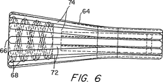
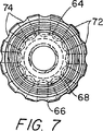
図6は図1および図2の生検鉗子工具のネジ山連結スリーブの拡大透過側面図である。
図7は図3のネジ山連結スリーブの基端の端面図である。
図8は図3のネジ山連結スリーブの末端の端面図である。
図9は本発明の生検鉗子工具の溝付接続部材の拡大側面図である。
図10は図6の溝付接続部材の透過斜視図である。
図11から図13は施錠部材を伴う溝付接続部材の組立体の係合状態の種々の段階の部分断面側面図である。
図14は本発明の生検鉗子工具のコイルを軸に接続する接続部分の第二の実施態様の部分断面側面図である。
発明の詳細な説明
図1から図4を参照すると、本発明による生検鉗子工具10は概して、基部ハンドル組立体12と、図示される実施態様では末端顎部組立体14である末端効果器とを有する。基部ハンドル組立体12は、中心スロット18を有する軸16と、軸16上で滑動可能なスプール20とを有する。軸16の末端には、外部二重螺旋ネジ山部23と貫通孔24とを有する円錐台状軸先端部22が設けられる。スプール20には、末端突部27と中心穴28とを有する交差ブロック26が設けられる。交差ブロック26はスプール20の基部にある溝25内に着座し、かつ軸16の中心スロット18を通過する。交差ブロック26の末端突部27は、溝25の床部にある穴29内で施錠され、かつ後に開示するラッチ受け口内へと延びる。中心穴28は、接続部材の基端が中心穴部28に入るのを許容するよう寸法決めされる。接続部材は後に開示する。
図1から図5を参照すると、スプール20の基端には、半径方向に延びるラッチ受け口32と、バネ34と、押しボタンラッチ36とを有する錠組立体が設けられる。図3に示すように、ラッチ受け口32が、円筒形状部分32aと溝部分32bとを有する。バネ34はラッチ受け口32の円筒形状部分32a内に着座し、ラッチ36はバネを介して延び、溝部分32b内に進入する。図2に示すように、ラッチ36は、ヘッド37と、末端側面部39aと、基部側面部39bと、キャッチ穴40と、インターロック穴42とを有する。キャッチ穴40は、後に開示するように、引っ張りワイヤ上に位置する接続部材を受容するのに十分に大きく、末端側面部39aのキャッチ穴40の周りにほぼ60°の面取部41が設けられるのが好ましい。面取部41は、キャッチ穴を介する接続部材の運動を容易にする。交差ブロック26上の末端突部27はインターロック穴42を介して延びる。インターロック穴42は末端突部27よりも大きく、その結果、インターロック穴42はラッチ36が受け口32内部で末端突部27に対して移動するのを許容する。さらに、インターロック穴42を介する末端突部27が延びているので、受け口32からラッチ36を解放するのを妨げる。バネ34はラッチのヘッド37と当接し、かつ受け口32内のラッチ36を付勢させ、後に開示するように、キャッチ穴40は案内穴と部分的に重なり合って整列するようになる。図1、図2、および図3を参照すると、スプール20にも案内部38が設けられ、この案内部38は、横方向でかつ末端方向に延びる部分44、46を有し、これら部分は案内穴48にテーパを付ける。案内部38は、スプール20内においてラッチ36の末端の方に位置し、以下に開示するように、引っ張りワイヤ上の接続部材がラッチ36と係合するよう案内する。
図1に示すように、末端顎部組立体14は、生検サンプル用の組織を把持して引き裂くための、対向する鋭い一対の顎部50、52を有する。顎部50、52はUリンクピン54周りに配置されるのが好ましく、Uリンクピン54は、比較的長い可撓性コイル58の末端にあるUリンク56に取り付けられるのが好ましい。コイル58は実質的に平滑なラップ60で被覆されるのが好ましく、ラップ60は基端において複数の棘状部(barb)62を有するのが好ましい。図1、図2、および図6から図8に示すように、二重螺旋構成部内の円錐台状基部開口部66と内部ネジ山部68とを有するネジ山連結スリーブ64がコイル58の基端に設けられる。ネジ山連結スリーブ64には複数の内部末端隆起部70が設けられるのが好ましく、製造時に棘状部62と係合する。軸16のネジ山円錐台状基端部22上におけるネジ山連結スリーブ64の捻り作用を容易にするために、ネジ山連結スリーブ64には複数の長手方向外部握り隆起部72と陥没部74とが設けられるのが好ましい。
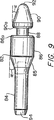
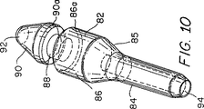
図示される実施形態では制御部材である引っ張りワイヤ80は引っ張りワイヤ80の末端で顎部50、52と連結され、かつ、コイル58と、ネジ山連結スリーブ64と、軸16の貫通孔24とを介して延び、中心スロット18に進入する。接続部材82は引っ張りワイヤ80の基端に設けられる。図9および図10を参照すると、接続部材82は概して、細長い円筒形末端部分84と、円錐台状部分85と、比較的大きい直径である円筒形中心部分86と、円筒形基部溝部分88と、丸みを付けた頂点を有するのが好ましい円錐基部部分90とを有する。細長い円筒形末端部分84は引っ張りワイヤ80を受容するボア94を有しており、それにより圧着作用によって引っ張りワイヤを接続部材に固定できるようになる。接続部材の末端部分84と溝部分88との外径はほぼ同一であるのが好ましい。円錐基部部分90は、接続部材の長手方向軸線に対して或る角度αで頂点92に向かってテーパを付けられ、ここで角度αは約15°から25°の間であるのが好ましい。円錐台状部分85は、接続部材の長手方向軸線に対して角度αで末端部分84に向かってテーパを付けられることも好ましい。後に開示するように、接続部材の錠組立体への挿入作用および取り外し作用を容易にするために、円筒形中心部分86の基部リム86aと円錐部分の末端リム90aとが斜切されるのが好ましい。
図11から図13を参照すると、引っ張りワイヤ80が単一動作でスプール20に連結されるようになるように、スプール内のラッチ36と引っ張りワイヤ80上の接続部材82とが配置される。特に、引っ張りワイヤ80の端部である接続部材が案内穴48を介して挿入され、それにより接続部材82はキャッチ穴40においてラッチ36と係合して(図11)キャッチ穴内に進入し、ラッチに接続部材の円錐部分90を出現させるようになる(図12)。キャッチ穴を介して接続部材をさらに挿入すると、接続部材の溝部分88がラッチを横切り、それによりラッチは溝部分と係合して接続部材を固定するようになる(図13)。
引っ張りワイヤ80がスプール20に連結された後には、ネジ山連結スリーブを軸先端部22上に移動させて単純な捻り動作を適用することによって、コイル58の基端においてネジ山連結スリーブ64が軸16に容易に連結される。軸先端部22とネジ山連結スリーブの基部開口部66との両方の円錐台形状部は、あらゆる捻り動作に先行してネジ山連結スリーブが軸先端部に亙って配置されるのを許容し、その結果、迅速な結合を可能とすることが理解される。円錐台形状と二重螺旋ネジ山部との組み合わせが、軸に対し連結スリーブ64を半回転させることにより、コイル58の軸16への結合作用を許容している。
末端組立体を基部ハンドルから容易に取り外し可能であることが理解される。連結スリーブはコイルを軸から解放するために軸に対して第一に回転せしめられる。次いで、ラッチ36が接続部材82の溝部分88を解放するまでラッチ36を押し下げることによって、引っ張りワイヤ80をスプール20から解放する。次いで、引っ張りワイヤをスプールから解放するために、接続部材をキャッチ穴40と案内穴48とを介して引っ張ることができる。次いで、基部ハンドルを他の末端組立体に対して再使用することができる。
図14を参照すると、第一の実施態様(類似の部品は、100を増した参照番号によって示される)の生検鉗子とほぼ類似である生検鉗子工具の第二の実施態様が示される。円錐台状末端開口部195と、内部二重螺旋ネジ山部196と、貫通孔124とが軸116に設けられる。コイル158を被覆する収縮ラップ160の基端にネジ山連結スリーブ164が設けられる。ネジ山連結スリーブ164は、二重螺旋構成部において円錐台状基端197と外部ネジ山部198とを有する。収縮ラップで被覆されたコイルの棘状部と係合するために、ネジ山連結スリーブ164には種々の内部隆起部170が設けられるのが好ましく、かつ開業医がスリーブを握ることを容易にするために、複数の長手方向の握り用隆起部172と陥没部とが設けられるのが好ましい。軸の末端開口部195にコネクタを挿入して、軸に対しネジ山連結スリーブを半回転させる単純な捻り動作を適用することによって、ネジ山連結スリーブ164を軸116に連結することができる。引っ張りワイヤ180はコイル158と、ネジ山連結スリーブ164と、貫通孔124とを介して延び、軸のスロット内に進入する。引っ張りワイヤの基端において接続部材は、軸上のスプール内に設けられた錠組立体によって係合せしめられる。
基部ハンドル組立体から取り外し可能な末端顎部組立体を有する内視鏡生検鉗子工具の実施態様がここでは説明されて図示されている。本発明の特別の実施態様が説明されているが、本発明はこの実施態様に制限されることを意図するものではなく、本発明が当該技術分野と同程度の広範な範囲を有していて明細書も同様に読まれることを意図するものである。従って、接続部材に関して特に好ましい形状と角度とが開示されているが、他の形状と角度でも十分であることが理解される。さらに、ネジ山連結スリーブと軸先端部とが円錐台状接続部分と二重螺旋ネジ山部の両方を有するよう開示されているが、円錐台状接続部分と二重螺旋ネジ山部とを別個に使用できることが理解される。さらに、圧着作用が引っ張りワイヤを接続部材に結合するために開示されているが、ハンダ付け作用、溶接作用、接着剤付け作用をも使用してもよいことが理解される。さらに、案内部は横方向および末端方向に延びる案内部分を有するよう示されているが、案内部が丸みを付けた漏斗の形状をとりうることも理解される。さらに、ラッチは突部において交差ブロックと結合されるよう示されているが、交差ブロックと結合する他のラッチが同様に使用されうることが理解される。さらに、末端効果器が鉗子の顎部であるとして示されているが、例えば把持装置、カッター、解剖器、およびハサミなどの他の末端効果器を使用してもよいことが理解される。さらに、一つの引っ張りワイヤが末端顎部と接続部材とに結合されるように開示されているが、二つの引っ張りワイヤを使用して同様に結合しうることが理解される。それゆえ、本発明の精神と範囲とから逸脱することなく、他の変更例を本発明に適用できることは当業者にとっては明らかである。The present invention is directed to US Pat. No. 5,454,378, assigned to the assignee of the present application, entitled “Biopsy Forceps with Removable Base Handle and Terminal Jaw”, which is hereby incorporated by reference in its entirety.
Field of Invention
The present invention relates generally to surgical tools. More particularly, the present invention relates to an endoscopic surgical tool having a removable base handle.
Conventional technology
Today, endoscopic surgery is widely performed around the world, and endoscopic surgery is quickly accepted. Generally, in endoscopic surgery, a camera or a magnifying glass inserted through a tube is used. On the other hand, cutters, dissection tools, or other surgical tools are inserted through other tubes for the purpose of manipulating and / or cutting internal organs or internal tissue under the surgeon's field of view. In an endoscopic biopsy procedure, a camera is located within one lumen of a typical flexible endoscope while a biopsy cutter is placed through the other lumen. Most endoscopic tools have a similar configuration with a base handle, an actuating mechanism, and an end effector coupled by a flexible tube or coil, with the end effect being achieved by the flexible tube or coil. The vessel is combined. An urging mechanism extends through these flexible tubes or coils. End effectors can take many forms such as grasping devices, cutters, forceps, dissectors, and the like.
Initially, endoscopic surgical tools are very expensive due to the partial reason that endoscopic surgical tools need to be very small but must be durable and reliable. The materials and manufacturing methods required to provide are expensive. In recent years, however, many “disposable” endoscopic tools have been introduced and the use of these endoscopes has gained wide acceptance. One advantage of disposable endoscopic tools over reusable tools is that they are used only for a single time, so there are no disinfection problems (eg, cross-patients between patients). There is no risk of contamination), and there is no concern about poor blade sharpness or chipping or wear of parts. However, in order to justify disposal of the tool after a single use, the disposable tool needs to be much less expensive than the reusable tool. In order to make the tool less expensive, disposable tools use less expensive materials. As a result, disposable tools may be less repairable than reusable tools. However, it is recognized that less durable components of disposable tools are often end effector components, and the durability of the base handle portion of the disposable tool is the base of the reusable tool. It is almost the same as the durability of the handle part. Furthermore, the end effector is not very fragile, so the end effector can only withstand a single use. Despite the advantages of the product, some surgeons sterilize disposable tools and reuse them several times to reduce the “cost per procedure”. Ultimately, however, it is the end portion of the tool that wears or breaks and delegates the processing of the entire disposable tool.
Among the disposable endoscopic tools in current use, there are many different types of biopsy forceps devices. These biopsy forceps devices often have opposing very sharp jaws for grasping and tearing the biopsy tissue. The jaws connect to each other with respect to the U link pin, which is attached to the U link. The U link extends into a housing that is crimped to the end of a relatively long flexible coil. The proximal end of the coil is coupled to a handle having means for engaging the jaw. The handle generally has an axially slotted shaft about which the spool is disposed. The puller wire from the jaws extends through the coil, and the puller wire is attached to the spool while the coil is attached to the central axis of the handle. The movement of the spool relative to the central axis moves the puller wire relative to the coil and thus attaches the jaw to the end of the coil. In use, the jaw and coil are inserted through a flexible endoscope already in place in the patient's body. The surgeon guides the coil and jaw to the biopsy site while the nurse holds the handle. When the surgeon places the jaw in the proper location, the nurse is instructed to engage the jaw and actuate the handle to grasp the biopsy sample. At the end of the biopsy procedure, the entire forceps device is either disposed of or washed and sterilized for reuse.
Known endoscopic biopsy forceps devices in the art have the disadvantage that the jaws wear out long before the useful life of the handle expires. Therefore, the entire tool needs to be disposed when the only part that does not work is a small part of the tool.
An endoscopic biopsy forceps device with a removable base handle and a distal portion is known and disclosed in US Pat. No. 4,763,668 to Macek et al. The disadvantages of the Machek et al. Removable biopsy forceps device are that screwing and unscrewing operations are required to attach and remove the base and distal portions, and complicate the attachment and removal procedures. The inconvenience of rotating the sleeve is also necessary.
U.S. Pat. No. 5,507,297, assigned to the present applicant by Slater et al., Discloses a laparoscopic tool having a removable base handle and a distal portion. These laparoscopic tools have a base assembly that can be inserted and removed from the base handle assembly in one step. The end assembly includes a tube, an end effector coupled to the tube, and a push rod coupled to the end effector and slidable through the tube. The base handle assembly has a tube sleeve for receiving the tube, manually actuated actuating means, and a latch for coupling the push rod to the actuating means. The tube sleeve is provided with a ball-type or blade-type locking portion that securely holds the tube at a predetermined position, and the tube is provided with a circumferential groove that engages with the ball-type or blade-type locking portion. The latch has a sloped surface that is spring loaded and hinged and quickly mates with the push bar and a non-latch surface that separates the push bar when biased by the non-latching member. The push rod is provided with a connecting proximal end which engages with a latch so that manually actuable actuating means can be connected to the push rod in the tube to actuate the end effector. Causes exercise. The coupling and separating action of the base assembly and the end assembly is rapid, in one step and almost automatic. However, the coupling action of the tube to the locking part is complicated and expensive to manufacture.
US Pat. No. 5,454,378, assigned to the present applicant by Palmer et al., Also discloses an endoscopic tool having a one-step coupling and separation action. The handle assembly of the endoscopic tool has a coupling device that removably couples the handle to the coil and the puller wire. A connection sleeve having a circumferential groove is provided at the proximal end of the coil, and a connection proximal end assembly is provided at the proximal end of the pull wire. The handle assembly has a centrally slotted shaft that carries a spool that has a cross block that passes through the central slot of the shaft. The end of the shaft is provided with a spring biased latch that engages a circumferential groove in the connecting sleeve of the coil. The cross block of the spool is provided with a pair of spring biased slides that engage the pull wire connection proximal end assembly. The connecting sleeve has a tapered proximal end so that when the connecting sleeve is inserted at the end of the handle shaft, the bias is applied until the sleeve is inserted at the point where the circumferential groove is engaged by the latch. Is moved to open the latch. The intersecting block is provided with a guide section tapered therein and is tapered so that the connection base end assembly of the pull wire is received and guided by the guide section. The sliding portion has an angled surface for receiving and locking the connection proximal end around the connection proximal end. Accordingly, the coil and the puller wire are coupled to the handle in a single motion by inserting the proximal end of the coil and the puller wire at the distal end of the handle shaft. The connection sleeve and connection proximal end assembly automatically engages the latches and slides in-plane with “snaps”, respectively. When released, the latch is actuated by a push button at the end of the handle shaft. By pushing the push button, the latch releases the coil, and the circumferential groove of the connecting sleeve can be slid from the engaged latch by pulling the coil. Pulling the coil from the handle also pulls a pull wire that is coupled to the cross block that includes the slide, which in turn results in pulling the cross block of the spool. As the cross block moves along the slotted axis closer to the base, the collar is engaged by a mechanism attached to the proximal end of the slotted axis. Next, the collar engages with the angled extension of the sliding part to release the sliding part. As a result, the connecting proximal end assembly of the pull wire is released, thus releasing the handle from the end assembly. While this tool has proven to be effective in providing an endoscopic tool having a handle that is separate from the end assembly, each of the spool coupling and the shaft coupling is very numerous. Are expensive and complicated to manufacture. Further, reassembly of the end assembly into the handle requires precise alignment of the coil and puller wire with respect to the spool coupling and shaft coupling, which is time consuming.
In Europe, endoscopic biopsy devices with removable handle assemblies have recently been marketed by Karl Schad. This endoscopic biopsy device has a relatively simple configuration. The handle assembly has a centrally slotted shaft that carries a spool with a cross block that can be removed from the central slot of the shaft, coil, and pull wire Passing through a coupling device coupled to. A cylindrical connecting sleeve having an internal thread is provided at the proximal end of the coil, and an external thread is provided at the end of the shaft so that the connecting sleeve and the shaft are connected to each other at the respective thread. It becomes united. A connection proximal end assembly is provided at the proximal end of the puller wire. The spool is provided with a spring biased latch that engages the connecting proximal end assembly. The connection proximal end assembly is engaged by depressing the latch, inserting the connection proximal end assembly into the hole provided in the latch, and releasing the latch. While the Karlshardt device represents a viable method for constructing an endoscopic tool having a removable handle assembly and a distal assembly, this device is not ideal. In order to couple the handle assembly to the pull wire and coil, two cumbersome process actions are required. First, the spring biased latch needs to be pushed down to receive the connection proximal assembly and released to engage the connection proximal assembly. This is an inconvenient way of coupling the pull wire to the spool. Next, it is necessary to insert the connecting sleeve over the shaft and rotate it several times with respect to the shaft, so that the coupling action by the fixing thread must be achieved between the connecting sleeve and the shaft. There is. This coupling method is time consuming.
Summary of the Invention
Therefore, it is an object of the present invention to provide an endoscopic biopsy forceps device in which the base handle and the distal jaw can be easily separated from each other so that the jaw can be abandoned without disposing of the handle Is to provide.
An object of the present invention is also an endoscopic biopsy forceps device in which the base handle and the distal jaw are easily removable from one another so that the base handle can be reused with a new set of distal jaws. Is to provide.
Another object of the present invention is to provide an endoscopic biopsy forceps device in which the base handle and distal jaw of the device can be quickly removed.
It is a further object of the present invention to provide an endoscopic biopsy forceps device in which the base handle and distal jaw of the device can be easily aligned for removal.
It is also an object of the present invention to provide an endoscopic biopsy forceps device that has a removable base handle and a distal jaw and is inexpensive and easy to manufacture.
Consistent with these objectives, discussed in detail below, the biopsy forceps of the present invention have a base handle assembly and a distal jaw assembly. The base handle assembly has a centrally slotted shaft provided with a distal portion having a double helical thread and a spool having a transversely seated cross block passing through the central slot. The spool is provided with a lock assembly having a push button latch biased by a spring. The distal jaw assembly has a pair of jaws that are mounted on the U-link at the distal end of the coil and coupled to a puller wire extending through the coil to the proximal end. A sleeve having a double helical thread is provided at the proximal end of the coil. The proximal end of the puller wire is provided with a grooved connecting member, the grooved connecting member comprising an elongated cylindrical end portion coupled to the puller wire, a cylindrical central portion having a relatively large diameter, and a cylindrical base portion A groove portion, a frustoconical portion, and a conical base portion having a rounded apex.
In the assembling operation of the biopsy forceps of the present invention, the connecting member on the pull wire is inserted into the lock assembly so that the spring-biased push button latch automatically engages the groove portion of the connecting member. As a result, the pull wire is coupled to the spool. The threaded sleeve on the coil is then joined to the end portion of the shaft by engaging the two and rotating the sleeve halfway. The base handle assembly and the distal jaw assembly are removed from each other by unscrewing the threaded sleeve from the shaft and depressing the spring-loaded latch push button.
A preferred embodiment of the invention has the provision of an internal double helical thread on the connecting sleeve and an external double helical thread at the shaft tip. Furthermore, the thread portion at the shaft tip is in the shape of a truncated cone, and the thread portion within the sleeve has a frustoconical opening for receiving the shaft tip.
Additional objects and advantages of the present invention will become apparent to those skilled in the art upon reference to the detailed description of the invention in conjunction with the accompanying drawings.
[Brief description of the drawings]
FIG. 1 is a partial cross-sectional side view of a biopsy forceps tool according to the present invention.
2 is an exploded perspective view of a proximal end portion of the biopsy forceps tool of FIG.
FIG. 3 is a partial cross-sectional side view of the spool of the biopsy forceps tool of FIGS. 1 and 2.
4 is a transparent perspective view of the spool of FIG.
FIG. 5 is an enlarged side view of the push button latch of the biopsy forceps tool of FIGS.
FIG. 6 is an enlarged transparent side view of the thread coupling sleeve of the biopsy forceps tool of FIGS. 1 and 2.
FIG. 7 is an end view of the proximal end of the thread coupling sleeve of FIG.
FIG. 8 is an end view of the distal end of the thread connection sleeve of FIG.
FIG. 9 is an enlarged side view of the grooved connecting member of the biopsy forceps tool of the present invention.
10 is a transparent perspective view of the grooved connection member of FIG.
11 to 13 are partial cross-sectional side views at various stages of engagement of the grooved connection member assembly with the locking member.
FIG. 14 is a partial cross-sectional side view of the second embodiment of the connecting portion for connecting the coil of the biopsy forceps tool of the present invention to the shaft.
Detailed Description of the Invention
Referring to FIGS. 1-4, a biopsy forceps tool 10 according to the present invention generally has a
Referring to FIGS. 1 to 5, a lock assembly having a radially extending
As shown in FIG. 1, the
In the illustrated embodiment, the pulling
11-13, the
After the
It is understood that the end assembly can be easily removed from the base handle. The connecting sleeve is first rotated relative to the shaft to release the coil from the shaft. The
Referring to FIG. 14, a second embodiment of a biopsy forceps tool is shown that is generally similar to the biopsy forceps of the first embodiment (similar parts are indicated by reference numbers increased by 100). A frustoconical end opening 195, an internal double
An embodiment of an endoscopic biopsy forceps tool having a distal jaw assembly removable from a base handle assembly is described and illustrated herein. While a particular embodiment of the present invention has been described, the present invention is not intended to be limited to this embodiment, and the present invention has a broad scope comparable to the art. The specification is intended to be read as well. Thus, although particularly preferred shapes and angles are disclosed for the connecting member, it will be understood that other shapes and angles are sufficient. Furthermore, although the thread coupling sleeve and the shaft tip are disclosed to have both a frustoconical connection and a double helical thread, the frustoconical connection and the double helical thread are separate. It is understood that can be used. Further, although a crimping action has been disclosed for coupling the pull wire to the connecting member, it will be understood that soldering, welding, and adhesive actions may also be used. Further, although the guide is shown as having a guide portion extending in the lateral and distal directions, it will be understood that the guide may take the form of a rounded funnel. Further, although the latch is shown as being coupled to the cross block at the protrusion, it is understood that other latches that couple to the cross block can be used as well. Further, although the end effector is shown as being a forceps jaw, it is understood that other end effectors may be used, such as grasping devices, cutters, dissectors, and scissors. Further, although one pull wire is disclosed to be coupled to the distal jaw and the connecting member, it is understood that two pull wires can be used to couple as well. Thus, it will be apparent to one skilled in the art that other modifications may be applied to the invention without departing from the spirit and scope of the invention.
Claims (24)
前記管状部材(58)の前記基端が、雄型および雌型の円錐台状ネジ山部分の一方を有するネジ山連結部材(64)を有し、
前記軸部材(16)の前記末端が、雄型および雌型の円錐台状ネジ山部分の他方を有しており、前記ネジ山連結部材(64)の、前記軸部材(16)の前記末端への螺合作用が前記管状部材(58)を前記軸部材(16)に結合させることを特徴とする生検鉗子工具。In the biopsy forceps tool (10) of an endoscope, a tubular member (58) having a proximal end and a distal end, a control member (80) extending through the tubular member (58), and a proximal end and a distal end And a sliding member (20) slidably attached to the shaft member (16). The sliding member (20) is detachably coupled to the control member (80). Coupling means (30) is provided, the biopsy forceps tool further comprises a distal effector (14), the distal effector (14) being the distal end of the control member (80) and the tubular member (58). The movement of the sliding member (20) relative to the shaft member (16) moves the end effector (14) from an open position to a closed position;
The proximal end of the tubular member (58) has a thread coupling member (64) having one of a male and female frustoconical thread portion;
The end of the shaft member (16) has the other of male and female frustoconical thread portions, and the end of the shaft member (16) of the thread connection member (64). A biopsy forceps tool, characterized in that the screwing action couples the tubular member (58) to the shaft member (16).
i)前記滑動部材(20)内のラッチ受け口(32)と、
ii)前記ラッチ受け口(32)内に着座しかつ前記接続部材(82)を受容するようになっているキャッチ穴(40)を画定するラッチ(36)と、
iii)前記ラッチ受け口(32)内に着座しかつ半径方向に外側に向かって前記ラッチ(36)を付勢するバネ(34)と、
iv)前記キャッチ穴(40)に概ね向かって前記接続部材を案内する案内穴(48)とを有しており、
前記キャッチ穴(40)と前記案内穴(48)とが部分的に重なり合う請求項4に記載の生検鉗子工具。The locking means (30)
i) a latch receptacle (32) in the sliding member (20);
ii) a latch (36) that seats in the latch receptacle (32) and defines a catch hole (40) adapted to receive the connecting member (82);
iii) a spring (34) seated in the latch receptacle (32) and biasing the latch (36) radially outward;
iv) a guide hole (48) for guiding the connecting member substantially toward the catch hole (40);
The biopsy forceps tool according to claim 4, wherein the catch hole (40) and the guide hole (48) partially overlap.
連結スリーブ(64)が雄型および雌型のネジ山接続部分のうちの一方を有し、前記連結スリーブ(64)が前記可撓性管状部材(58)の前記基端に結合されかつ、前記軸(16)に対し前記連結スリーブ(64)を一回転よりも少なく回転させることにより、前記軸(16)の末端の接続手段に迅速に結合されるようになっている末端組立体。End assembly for an endoscopic biopsy forceps tool (10), wherein the biopsy forceps tool (10) is slidably mounted on a base push handle having a shaft (16) and the shaft A sliding member (20), the shaft (16) having a distal connecting means, the sliding member (20) having a coupling means, and the distal assembly comprising a proximal end and a distal end A flexible tubular member (58) having a proximal end and a distal end and extending through the flexible tubular member (58); and sliding the control member (80) A terminal assembly comprising connecting means (82) for fast coupling to the coupling means of the member (20);
A coupling sleeve (64) having one of a male and a female thread connection, the coupling sleeve (64) being coupled to the proximal end of the flexible tubular member (58); and An end assembly adapted to be quickly coupled to the connecting means at the end of the shaft (16) by rotating the connecting sleeve (64) less than one turn relative to the shaft (16).
前記軸部材(16)が、前記軸部材(16)に対し第一結合手段を一回転よりも少なく回転させることにより、前記軸部材(16)を可撓性管状部材(58)の第一結合手段に迅速に結合するようになっている雄型および雌型のネジ山連結部分のうちの一方を有する基部ハンドル組立体。In a base handle assembly (12) for an endoscopic biopsy forceps tool (10), the biopsy forceps tool (10) has a flexible tubular member (58) having a proximal end and a distal end. The proximal end of the flexible tubular member (58) has a first coupling means, and the biopsy forceps tool (10) further has a proximal end and a distal end, and the flexible tubular member (58 ), The control member (80) having a second coupling means (82) at its proximal end, and the biopsy forceps tool (10) further comprising a flexible tubular member (58) and a distal end effector assembly (14) coupled to the distal ends of the control member (80), the base handle assembly (12) having a shaft member having a proximal end and a distal end (12). 16) and a sliding member (20) slidably attached to the shaft member (16), the sliding member (20) being slid In wood second coupling means (82) to the base handle assembly having a quick coupling means for quickly coupling (20) a control member (80) (12),
The shaft member (16) rotates the first coupling means with respect to the shaft member (16) by less than one rotation, so that the shaft member (16) is first coupled to the flexible tubular member (58). A base handle assembly having one of a male and female threaded coupling portion adapted for rapid coupling to the means.
i)前記滑動部材(20)内にあるラッチ受け口(32)と、
ii)前記ラッチ受け口(32)内に着座し、かつ第二結合手段(82)を受容するようになっているキャッチ穴(40)を画定するラッチ(36)と、
iii)前記ラッチ受け口(32)内に着座し、かつ前記ラッチ(36)を半径方向に外側に付勢するバネ(34)と、
iv)第二結合手段(82)を前記キャッチ穴(40)に向かって案内する案内穴(48)とを具備し、
前記キャッチ穴(40)と前記案内穴(48)とが部分的に重なり合う請求項21に記載の基部ハンドル組立体。Quick coupling means for rapidly coupling the sliding member (20) to the second coupling means (82) of the control member (80);
i) a latch receptacle (32) in the sliding member (20);
ii) a latch (36) seated in said latch receptacle (32) and defining a catch hole (40) adapted to receive a second coupling means (82);
iii) a spring (34) seated in the latch receptacle (32) and biasing the latch (36) radially outward;
iv) a guide hole (48) for guiding the second coupling means (82) toward the catch hole (40);
The base handle assembly of claim 21, wherein the catch hole (40) and the guide hole (48) partially overlap.
Applications Claiming Priority (3)
| Application Number | Priority Date | Filing Date | Title |
|---|---|---|---|
| US08/779,034 | 1997-01-06 | ||
| US08/779,034 US5964717A (en) | 1997-01-06 | 1997-01-06 | Biopsy forceps having detachable handle and distal jaws |
| PCT/US1998/000080 WO1998030149A1 (en) | 1997-01-06 | 1998-01-06 | Biopsy forceps having detachable handle and distal jaws |
Publications (3)
| Publication Number | Publication Date |
|---|---|
| JP2001508339A JP2001508339A (en) | 2001-06-26 |
| JP2001508339A5 JP2001508339A5 (en) | 2005-09-08 |
| JP4094677B2 true JP4094677B2 (en) | 2008-06-04 |
Family
ID=25115112
Family Applications (1)
| Application Number | Title | Priority Date | Filing Date |
|---|---|---|---|
| JP53099398A Expired - Fee Related JP4094677B2 (en) | 1997-01-06 | 1998-01-06 | Biopsy forceps with removable handle and distal jaw |
Country Status (6)
| Country | Link |
|---|---|
| US (2) | US5964717A (en) |
| EP (1) | EP0998223B1 (en) |
| JP (1) | JP4094677B2 (en) |
| CA (1) | CA2274868C (en) |
| DE (1) | DE69830727T2 (en) |
| WO (1) | WO1998030149A1 (en) |
Families Citing this family (54)
| Publication number | Priority date | Publication date | Assignee | Title |
|---|---|---|---|---|
| US7090683B2 (en) | 1998-02-24 | 2006-08-15 | Hansen Medical, Inc. | Flexible instrument |
| US6949106B2 (en) | 1998-02-24 | 2005-09-27 | Endovia Medical, Inc. | Surgical instrument |
| US7214230B2 (en) | 1998-02-24 | 2007-05-08 | Hansen Medical, Inc. | Flexible instrument |
| US7775972B2 (en) | 1998-02-24 | 2010-08-17 | Hansen Medical, Inc. | Flexible instrument |
| US7713190B2 (en) | 1998-02-24 | 2010-05-11 | Hansen Medical, Inc. | Flexible instrument |
| US6810281B2 (en) | 2000-12-21 | 2004-10-26 | Endovia Medical, Inc. | Medical mapping system |
| US8414598B2 (en) | 1998-02-24 | 2013-04-09 | Hansen Medical, Inc. | Flexible instrument |
| US6162216A (en) * | 1998-03-02 | 2000-12-19 | Guziak; Robert Andrew | Method for biopsy and ablation of tumor cells |
| EP1005836A1 (en) * | 1998-12-03 | 2000-06-07 | Nivarox-FAR S.A. | Surgical instrument having detachable handle and operating unit |
| US6537205B1 (en) | 1999-10-14 | 2003-03-25 | Scimed Life Systems, Inc. | Endoscopic instrument system having reduced backlash control wire action |
| US6743185B2 (en) * | 2000-09-26 | 2004-06-01 | Scimed Life Systems, Inc. | Handle assembly for surgical instrument and method of making the assembly |
| DE10064623C1 (en) | 2000-12-22 | 2002-08-22 | Winter & Ibe Olympus | Endoscopic surgery forceps |
| US7766894B2 (en) | 2001-02-15 | 2010-08-03 | Hansen Medical, Inc. | Coaxial catheter system |
| US7699835B2 (en) | 2001-02-15 | 2010-04-20 | Hansen Medical, Inc. | Robotically controlled surgical instruments |
| US8414505B1 (en) | 2001-02-15 | 2013-04-09 | Hansen Medical, Inc. | Catheter driver system |
| US20030135204A1 (en) * | 2001-02-15 | 2003-07-17 | Endo Via Medical, Inc. | Robotically controlled medical instrument with a flexible section |
| US20040176751A1 (en) | 2002-08-14 | 2004-09-09 | Endovia Medical, Inc. | Robotic medical instrument system |
| US20040167430A1 (en) * | 2003-02-20 | 2004-08-26 | Roshdieh Babak B. | Cutaneous biopsy device with handle and disposable tips |
| US7837631B2 (en) * | 2003-03-14 | 2010-11-23 | Boston Scientific Scimed Inc. | Biopsy forceps with removable jaw segments |
| WO2005063127A1 (en) * | 2003-12-23 | 2005-07-14 | Cook Urological Incorporated | Back loading endoscopic instruments |
| US8444657B2 (en) * | 2004-05-07 | 2013-05-21 | Usgi Medical, Inc. | Apparatus and methods for rapid deployment of tissue anchors |
| US7905857B2 (en) | 2005-07-11 | 2011-03-15 | Covidien Ag | Needle assembly including obturator with safety reset |
| US7850650B2 (en) | 2005-07-11 | 2010-12-14 | Covidien Ag | Needle safety shield with reset |
| US7828773B2 (en) | 2005-07-11 | 2010-11-09 | Covidien Ag | Safety reset key and needle assembly |
| DE602006008740D1 (en) * | 2005-01-20 | 2009-10-08 | Wilson Cook Medical Inc | BIOPSY FORCEPS |
| US20060276747A1 (en) | 2005-06-06 | 2006-12-07 | Sherwood Services Ag | Needle assembly with removable depth stop |
| US20060282097A1 (en) * | 2005-06-13 | 2006-12-14 | Ortiz Mark S | Surgical suturing apparatus with a non-visible spectrum sensing member |
| US7731692B2 (en) | 2005-07-11 | 2010-06-08 | Covidien Ag | Device for shielding a sharp tip of a cannula and method of using the same |
| US7654735B2 (en) | 2005-11-03 | 2010-02-02 | Covidien Ag | Electronic thermometer |
| US7918783B2 (en) | 2006-03-22 | 2011-04-05 | Boston Scientific Scimed, Inc. | Endoscope working channel with multiple functionality |
| US8313500B2 (en) | 2006-04-14 | 2012-11-20 | Ethicon Endo-Surgery, Inc. | Endoscopic device |
| US7998167B2 (en) | 2006-04-14 | 2011-08-16 | Ethicon Endo-Surgery, Inc. | End effector and method of manufacture |
| US7857827B2 (en) | 2006-04-14 | 2010-12-28 | Ethicon Endo-Surgery, Inc. | Endoscopic device |
| CN101677824B (en) * | 2006-06-30 | 2017-11-28 | 史蒂夫·利夫内 | Surgical instruments with detachable tool assembly |
| US20080021278A1 (en) * | 2006-07-24 | 2008-01-24 | Leonard Robert F | Surgical device with removable end effector |
| EP2083715B1 (en) * | 2006-11-30 | 2013-03-13 | Cook Medical Technologies LLC | Removable handle for medical device |
| WO2008101497A1 (en) * | 2007-02-19 | 2008-08-28 | Multi Biopsy Sampling Co. Aps | Biopsy forceps for taking one or more samples |
| US8357104B2 (en) | 2007-11-01 | 2013-01-22 | Coviden Lp | Active stylet safety shield |
| DE102009022379A1 (en) * | 2009-05-22 | 2010-11-25 | Epflex Feinwerktechnik Gmbh | Interchangeable handle system, especially for medical instruments |
| US8956341B2 (en) * | 2010-06-10 | 2015-02-17 | Carefusion 2200, Inc. | Surgical device with reusable handle |
| US8840630B2 (en) | 2011-06-15 | 2014-09-23 | Cook Medical Technologies Llc | Button release handle |
| US9597152B2 (en) * | 2011-09-10 | 2017-03-21 | Cook Medical Technologies Llc | Control handles for medical devices |
| JP6076491B2 (en) * | 2013-02-20 | 2017-02-08 | オリンパス株式会社 | Medical manipulator |
| US9987036B2 (en) | 2014-10-03 | 2018-06-05 | Covidien Lp | System and method for powering an ultrasonic surgical device |
| US10194892B2 (en) * | 2014-10-15 | 2019-02-05 | Karl Storz Endovision, Inc. | Detachable articulating endoscopic tool cartridge |
| US9700445B2 (en) | 2014-11-04 | 2017-07-11 | Abbott Cardiovascular Systems, Inc. | One-way actuator knob |
| US10376673B2 (en) | 2015-06-19 | 2019-08-13 | Evalve, Inc. | Catheter guiding system and methods |
| US10238494B2 (en) | 2015-06-29 | 2019-03-26 | Evalve, Inc. | Self-aligning radiopaque ring |
| US10413408B2 (en) | 2015-08-06 | 2019-09-17 | Evalve, Inc. | Delivery catheter systems, methods, and devices |
| US10238495B2 (en) * | 2015-10-09 | 2019-03-26 | Evalve, Inc. | Delivery catheter handle and methods of use |
| USD809139S1 (en) | 2015-10-09 | 2018-01-30 | Evalve, Inc. | Handle for a medical device |
| US10252035B2 (en) | 2015-12-07 | 2019-04-09 | Cook Medical Techonologies Llc | Rotatable control handles for medical devices and methods of using rotatable control handles |
| CN110037751B (en) * | 2019-04-25 | 2022-05-27 | 江苏华创高新医疗科技有限公司 | Sampling tool for tumor slices |
| CN113066768B (en) * | 2021-03-19 | 2022-06-10 | 深圳市嘉兴南电科技有限公司 | Fill diode for electric pile with good clamping capacity |
Family Cites Families (18)
| Publication number | Priority date | Publication date | Assignee | Title |
|---|---|---|---|---|
| US4763668A (en) * | 1985-10-28 | 1988-08-16 | Mill Rose Laboratories | Partible forceps instrument for endoscopy |
| DE3632786A1 (en) * | 1986-09-26 | 1988-03-31 | Wolfgang Griesat | Instrument for surgical interventions in body cavities |
| US4971067A (en) * | 1988-05-05 | 1990-11-20 | Lee Bolduc | Biopsy instrument with a disposable cutting blade |
| US4944741A (en) * | 1988-12-09 | 1990-07-31 | Hasson Harrith M | Laproscopic instrument with pivotable support arm |
| US5507297A (en) * | 1991-04-04 | 1996-04-16 | Symbiosis Corporation | Endoscopic instruments having detachable proximal handle and distal portions |
| US5454378A (en) * | 1993-02-11 | 1995-10-03 | Symbiosis Corporation | Biopsy forceps having a detachable proximal handle and distal jaws |
| US5304024A (en) * | 1991-03-18 | 1994-04-19 | Adolf Wurth Gmbh & Co. Kg | Screw, method and rolling die for the production thereof |
| US5391166A (en) * | 1991-06-07 | 1995-02-21 | Hemostatic Surgery Corporation | Bi-polar electrosurgical endoscopic instruments having a detachable working end |
| DE69231100T2 (en) * | 1991-08-21 | 2001-02-15 | Smith & Nephew Inc | Fluid treatment system |
| US5368606A (en) * | 1992-07-02 | 1994-11-29 | Marlow Surgical Technologies, Inc. | Endoscopic instrument system |
| US5308358A (en) * | 1992-08-25 | 1994-05-03 | Bond Albert L | Rigid-shaft surgical instruments that can be disassembled for improved cleaning |
| DE4323584A1 (en) * | 1993-07-14 | 1995-01-19 | Delma Elektro Med App | Detachable medical instrument |
| US5507774A (en) * | 1993-07-19 | 1996-04-16 | Wright Medical Technology, Inc. | Surgical instrument capable of disassembly |
| DE4332497C2 (en) * | 1993-09-24 | 1997-04-24 | Stefan Koscher | Surgical instrument |
| DE4341736A1 (en) * | 1993-12-08 | 1995-06-14 | Aesculap Ag | Surgical tubular shaft instrument |
| US5385561A (en) * | 1994-01-18 | 1995-01-31 | Bard International, Inc. | Apparatus and method for injecting a viscous material into the tissue of a patient |
| DE9418094U1 (en) * | 1994-11-15 | 1995-01-12 | Tontarra Medizintechnik Gmbh | Surgical tubular shaft instrument |
| US5603723A (en) * | 1995-01-11 | 1997-02-18 | United States Surgical Corporation | Surgical instrument configured to be disassembled for cleaning |
-
1997
- 1997-01-06 US US08/779,034 patent/US5964717A/en not_active Expired - Lifetime
- 1997-09-16 US US08/931,753 patent/US6007560A/en not_active Expired - Lifetime
-
1998
- 1998-01-06 JP JP53099398A patent/JP4094677B2/en not_active Expired - Fee Related
- 1998-01-06 DE DE69830727T patent/DE69830727T2/en not_active Expired - Fee Related
- 1998-01-06 WO PCT/US1998/000080 patent/WO1998030149A1/en active IP Right Grant
- 1998-01-06 EP EP98901166A patent/EP0998223B1/en not_active Expired - Lifetime
- 1998-01-06 CA CA002274868A patent/CA2274868C/en not_active Expired - Fee Related
Also Published As
| Publication number | Publication date |
|---|---|
| CA2274868C (en) | 2006-07-11 |
| DE69830727T2 (en) | 2005-12-01 |
| JP2001508339A (en) | 2001-06-26 |
| EP0998223A1 (en) | 2000-05-10 |
| DE69830727D1 (en) | 2005-08-04 |
| EP0998223B1 (en) | 2005-06-29 |
| WO1998030149A1 (en) | 1998-07-16 |
| US6007560A (en) | 1999-12-28 |
| CA2274868A1 (en) | 1998-07-16 |
| US5964717A (en) | 1999-10-12 |
Similar Documents
| Publication | Publication Date | Title |
|---|---|---|
| JP4094677B2 (en) | Biopsy forceps with removable handle and distal jaw | |
| US5782748A (en) | Endoscopic surgical instruments having detachable proximal and distal portions | |
| US6561988B1 (en) | Endoscopic multiple sample bioptome with enhanced biting action | |
| US5797957A (en) | Endoscopic bioptome with a hard stop to control biting force | |
| US5454378A (en) | Biopsy forceps having a detachable proximal handle and distal jaws | |
| US9775633B2 (en) | Medical device handles and related methods of use | |
| EP0843533B1 (en) | Endoscopic multiple sample bioptome | |
| US5545170A (en) | Surgical instrument | |
| US20090171147A1 (en) | Surgical instrument | |
| US6595984B1 (en) | Laparoscopic instrument with a detachable tip | |
| JP2007500569A (en) | Surgical instrument and method having a removable shaft device | |
| JP2020025857A (en) | Rotation knob assemblies and surgical instruments including the same | |
| US6461310B1 (en) | Endoscopic bioptome with a hard stop to control biting force | |
| EP3917409A1 (en) | Anastomosis device | |
| KR20230162693A (en) | Over-the-scope clip with compliance mechanism |
Legal Events
| Date | Code | Title | Description |
|---|---|---|---|
| A521 | Written amendment |
Free format text: JAPANESE INTERMEDIATE CODE: A523 Effective date: 20050106 |
|
| A621 | Written request for application examination |
Free format text: JAPANESE INTERMEDIATE CODE: A621 Effective date: 20050106 |
|
| A131 | Notification of reasons for refusal |
Free format text: JAPANESE INTERMEDIATE CODE: A131 Effective date: 20070619 |
|
| A601 | Written request for extension of time |
Free format text: JAPANESE INTERMEDIATE CODE: A601 Effective date: 20070918 |
|
| A602 | Written permission of extension of time |
Free format text: JAPANESE INTERMEDIATE CODE: A602 Effective date: 20071029 |
|
| A521 | Written amendment |
Free format text: JAPANESE INTERMEDIATE CODE: A523 Effective date: 20071214 |
|
| TRDD | Decision of grant or rejection written | ||
| A01 | Written decision to grant a patent or to grant a registration (utility model) |
Free format text: JAPANESE INTERMEDIATE CODE: A01 Effective date: 20080205 |
|
| A61 | First payment of annual fees (during grant procedure) |
Free format text: JAPANESE INTERMEDIATE CODE: A61 Effective date: 20080306 |
|
| FPAY | Renewal fee payment (event date is renewal date of database) |
Free format text: PAYMENT UNTIL: 20110314 Year of fee payment: 3 |
|
| R150 | Certificate of patent or registration of utility model |
Free format text: JAPANESE INTERMEDIATE CODE: R150 |
|
| LAPS | Cancellation because of no payment of annual fees |