JP4092237B2 - Fiber rope for rope - Google Patents
Fiber rope for rope Download PDFInfo
- Publication number
- JP4092237B2 JP4092237B2 JP2003094016A JP2003094016A JP4092237B2 JP 4092237 B2 JP4092237 B2 JP 4092237B2 JP 2003094016 A JP2003094016 A JP 2003094016A JP 2003094016 A JP2003094016 A JP 2003094016A JP 4092237 B2 JP4092237 B2 JP 4092237B2
- Authority
- JP
- Japan
- Prior art keywords
- fiber
- rope
- composite
- strand
- bundles
- Prior art date
- Legal status (The legal status is an assumption and is not a legal conclusion. Google has not performed a legal analysis and makes no representation as to the accuracy of the status listed.)
- Expired - Fee Related
Links
- 239000000835 fiber Substances 0.000 title claims description 242
- 239000002131 composite material Substances 0.000 claims description 129
- 238000001514 detection method Methods 0.000 claims description 68
- 239000002184 metal Substances 0.000 claims description 67
- 239000011247 coating layer Substances 0.000 claims description 12
- 230000002093 peripheral effect Effects 0.000 claims description 7
- 239000010410 layer Substances 0.000 claims description 6
- 229910000831 Steel Inorganic materials 0.000 description 40
- 239000010959 steel Substances 0.000 description 40
- 238000005452 bending Methods 0.000 description 7
- 238000012986 modification Methods 0.000 description 7
- 230000004048 modification Effects 0.000 description 7
- 230000006866 deterioration Effects 0.000 description 6
- 238000009661 fatigue test Methods 0.000 description 5
- -1 polyethylene Polymers 0.000 description 5
- 239000004698 Polyethylene Substances 0.000 description 4
- 229920000573 polyethylene Polymers 0.000 description 4
- 229920006231 aramid fiber Polymers 0.000 description 3
- 230000007797 corrosion Effects 0.000 description 3
- 238000005260 corrosion Methods 0.000 description 3
- 238000003745 diagnosis Methods 0.000 description 3
- 229920003002 synthetic resin Polymers 0.000 description 3
- 239000000057 synthetic resin Substances 0.000 description 3
- 239000004760 aramid Substances 0.000 description 2
- 239000000470 constituent Substances 0.000 description 2
- 238000000034 method Methods 0.000 description 2
- 229920002994 synthetic fiber Polymers 0.000 description 2
- 239000012209 synthetic fiber Substances 0.000 description 2
- 239000004743 Polypropylene Substances 0.000 description 1
- 238000009954 braiding Methods 0.000 description 1
- 239000011248 coating agent Substances 0.000 description 1
- 238000000576 coating method Methods 0.000 description 1
- 238000001816 cooling Methods 0.000 description 1
- 238000002788 crimping Methods 0.000 description 1
- 239000004519 grease Substances 0.000 description 1
- 208000014674 injury Diseases 0.000 description 1
- 239000000463 material Substances 0.000 description 1
- 229920001155 polypropylene Polymers 0.000 description 1
- 230000008733 trauma Effects 0.000 description 1
Images


Classifications
-
- D—TEXTILES; PAPER
- D07—ROPES; CABLES OTHER THAN ELECTRIC
- D07B—ROPES OR CABLES IN GENERAL
- D07B1/00—Constructional features of ropes or cables
- D07B1/06—Ropes or cables built-up from metal wires, e.g. of section wires around a hemp core
- D07B1/0673—Ropes or cables built-up from metal wires, e.g. of section wires around a hemp core having a rope configuration
-
- D—TEXTILES; PAPER
- D07—ROPES; CABLES OTHER THAN ELECTRIC
- D07B—ROPES OR CABLES IN GENERAL
- D07B1/00—Constructional features of ropes or cables
- D07B1/02—Ropes built-up from fibrous or filamentary material, e.g. of vegetable origin, of animal origin, regenerated cellulose, plastics
- D07B1/025—Ropes built-up from fibrous or filamentary material, e.g. of vegetable origin, of animal origin, regenerated cellulose, plastics comprising high modulus, or high tenacity, polymer filaments or fibres, e.g. liquid-crystal polymers
-
- D—TEXTILES; PAPER
- D07—ROPES; CABLES OTHER THAN ELECTRIC
- D07B—ROPES OR CABLES IN GENERAL
- D07B1/00—Constructional features of ropes or cables
- D07B1/14—Ropes or cables with incorporated auxiliary elements, e.g. for marking, extending throughout the length of the rope or cable
- D07B1/145—Ropes or cables with incorporated auxiliary elements, e.g. for marking, extending throughout the length of the rope or cable comprising elements for indicating or detecting the rope or cable status
-
- D—TEXTILES; PAPER
- D07—ROPES; CABLES OTHER THAN ELECTRIC
- D07B—ROPES OR CABLES IN GENERAL
- D07B1/00—Constructional features of ropes or cables
- D07B1/16—Ropes or cables with an enveloping sheathing or inlays of rubber or plastics
- D07B1/162—Ropes or cables with an enveloping sheathing or inlays of rubber or plastics characterised by a plastic or rubber enveloping sheathing
Landscapes
- Chemical & Material Sciences (AREA)
- Crystallography & Structural Chemistry (AREA)
- Ropes Or Cables (AREA)
- Lift-Guide Devices, And Elevator Ropes And Cables (AREA)
Description
【0001】
【技術分野】
この発明は,クレーン用の動索,エレベータ用の動索,その他の用途に用いられる動索用繊維ロープに関する。
【0002】
【従来技術】
動索として,ワイヤロープが使用されている。一般的に動索に使用するワイヤロープは,中心に繊維束を配置し,その周りに鋼製のストランドを撚り合わせた構造のものである。繊維束は,その周りに撚り合わせたストランドを支えてワイヤロープの形状を保つとともに,グリースをストランドに補給してストランドの損傷,腐食を防ぐ。鋼製のストランドがワイヤロープの主構成要素であるから,軽量化を図ることが難しい。
【0003】
一方,繊維ロープは,鋼製の同径のワイヤロープに比べ,軽量であり,柔軟性があり,繰り返し引張りおよび曲げに対する疲労強度があるが,損傷等の検出または劣化の診断が困難であるため,動索として使用することが困難である。
【0004】
【発明の開示】
この発明は,損傷等の検出または劣化の診断が容易にできる動索用繊維ロープを提供することを目的とする。
【0005】
第1の発明による動索用繊維ロープは,少なくとも一本の複合ストランドと少なくとも一本の繊維ストランドとが撚り合わされて繊維裸ロープが構成され,この繊維裸ロープの外側周囲を覆うように被覆層が形成され,上記複合ストランドは,少なくとも一束の複合繊維束と少なくとも一束の繊維束とが撚り合わされて,または複数束の複合繊維束が撚り合わされて構成され,上記複合繊維束には,繊維よりも伸びの大きい,寿命検知用金属線,または複数本の金属線が撚り合わされてなる寿命検知用金属撚り線が含まれているものである。
【0006】
撚り合わされて繊維裸ロープを構成する複合ストランドと繊維ストランドとの本数および配置は動索用繊維ロープの径の大きさ,要求される強度等に応じて定められる。少なくとも一本の複合ストランドと少なくとも一本の繊維ストランドとが含まれていればよい。複合ストランドおよび繊維ストランドの撚り方,形状および径の大きさは,動索用繊維ロープの形状,径の大きさ,要求される引張り,曲げに対する強度等に応じて定められる。
【0007】
繊維裸ロープの外側周囲にこれを覆うように形成される被覆層は,合成樹脂を繊維裸ロープの外周面に溶着するまたは密着させる,合成樹脂テープを繊維裸ロープの外周に巻回する,合成繊維によって編組する,これらを組合せる等の方法によって形成することができる。さらに被覆層の厚さは動索用繊維ロープの径の大きさ,要求される被覆層の強度等に応じて定められる。被覆層により,動索用繊維ロープの摩擦による外傷または腐食を防ぐことができる。
【0008】
複合ストランドは,少なくとも一束の複合繊維束と少なくとも一束の繊維束とが撚り合わされて,または複数束の複合繊維束が撚り合わされて構成される。撚り合わされる複合繊維束および繊維束の束数および配置はそれぞれ要求される径,強度等に応じて定められる。
【0009】
繊維ストランドは,複数束の繊維束が撚り合わされて構成される。繊維束は,アラミド繊維等の合成繊維または天然繊維等の多数本のフィラメント(繊維)を束ね合わせたものである。
【0010】
これらの複合ストランドまたは繊維ストランドを構成するための複合繊維束または繊維束の撚り方,形状および径の大きさは,動索用繊維ロープの形状,径の大きさ,要求される引張り,曲げに対する強度等に応じて定められる。
【0011】
複合ストランドの構成要素である複合繊維束は,寿命検知用金属線(1本もしくは複数本),または複数本の金属線が撚り合わされてなる寿命検知用金属撚り線(1本もしくは複数本)が,アラミド繊維等の合成繊維または天然繊維等の多数本のフィラメント(繊維)とともに束ねられているものである。寿命検知用金属線または寿命検知用金属撚り線は,多数本のフィラメントのどこに(中央でも,周辺でも)位置していてもよい。
【0012】
寿命検知用金属線は,スチールワイヤ等を含む電導性の金属線である。寿命検知用金属撚り線は,複数本の金属線を撚り合わせたものである。寿命検知用金属線の,または寿命検知用金属撚り線を構成する金属線の材質,断面形状,径の大きさおよび本数は,動索用繊維ロープの損傷,劣化等により動索用繊維ロープを交換すべき時期(動索用繊維ロープの寿命がきた時期)に断線するような,または断線が検知されるような強度をもつように設定される。
【0013】
いずれにしても,寿命検知用金属線または寿命検知用金属撚り線は,動索用繊維ロープの一端から他端までとぎれることなく(断線していることなく)連続的につながった状態で複合繊維束内に設けられる。
【0014】
寿命検知用金属線または寿命検知用金属撚り線は動索用繊維ロープに加わる負荷(主に引張り荷重)を負担する必要はない。むしろ,寿命検知用金属線または寿命検知用金属撚り線が動索用繊維ロープに加わる負荷を負担しないようにすることが望ましい。このために寿命検知用金属線または寿命検知用金属撚り線は,負荷を負担する繊維(繊維束,複合繊維束,繊維ストランドまたは複合ストランドを構成するもの)よりも伸びが大きいものとする。もちろん,寿命検知用金属線または寿命検知用金属撚り線は動索用繊維ロープと一緒に曲がるもの(曲げやすいもの)であることが前提である。
【0015】
寿命検知用金属線を繊維よりも伸びの大きなものにするために,一実施態様では,寿命検知用金属線の外周面に,長手方向に沿って凹溝または凸条を螺旋状に形成する(クリンプ加工)。寿命検知用金属撚り線は,短い撚りピッチで撚ることにより(好ましくは,複合ストランドの撚りピッチよりも短く),伸びやすくすることができる。
【0016】
以上のように動索用繊維ロープは,基本的には(負荷を負担する部分についていうと),繊維ロープであるから,同径の鋼製のロープよりも軽量であり,弾性係数が小さく,疲労強度がある。すわなち,動索用繊維ロープは軽量であり,曲げやすく,繰返し引張りおよび曲げに対して疲労しにくい。また動索用繊維ロープには,その長手方向に沿って一または複数本の寿命検知用金属線または寿命検知用金属撚り線が入っているので,ワイヤロープの損傷検出器(その一例が実開平6−87861号に示されている)を使用して寿命検知用金属線または寿命検知用金属撚り線の損傷等による断線の箇所を容易に検出することができる。寿命検知用金属線または寿命検知用金属撚り線の断線が検出されたときには,動索用繊維ロープにも損傷等が生じている,劣化している,または損傷等が生じるであろう,劣化の時期にきているであろう,したがって動索用繊維ロープには寿命がきており,交換すべき時期であると予測できる。これにより,動索用繊維ロープの交換時期を誤ることなく,安全性を確保できる。
【0017】
第2の発明による動索用繊維ロープは,複数本の複合ストランドが撚り合わされて繊維裸ロープが構成され,この繊維裸ロープの外側周囲を覆うように被覆層が形成され,上記複合ストランドは,少なくとも一束の複合繊維束と少なくとも一束の繊維束とが撚り合わされて,または複数束の複合繊維束が撚り合わされて構成され,上記複合繊維束には,繊維よりも伸びの大きい,寿命検知用金属線,または複数本の金属線が撚り合わされてなる寿命検知用金属撚り線が含まれているものである。
【0018】
本願第2発明による動索用繊維ロープと,第1の発明による動索用繊維ロープとの違いは,第1の発明による動索用繊維ロープが少なくとも一本の複合ストランドと少なくとも一本の繊維ストランドを含むのに対して,第2の発明による動索用繊維ロープは,複数本の複合ストランドを撚り合わせて繊維裸ロープが構成される点にある。第2の発明による動索用繊維ロープは,複数本の複合ストランドにより構成されており,複合ストランドは,少なくとも1束の複合繊維束を含でいる。複合繊維束には,寿命検知用金属線(1本もしくは複数本)または寿命検知用金属撚り線(1本もしくは複数本)が入っているので,寿命検知用金属線または寿命検知用金属撚り線の断線検知により,動索用繊維ロープ全体の損傷等の検出または劣化の診断が容易に可能となる。さらに主要構成が繊維ロープであるため,軽量化を図り,曲げ,引張りに対して疲労強度を高めることができる。
【0019】
第3の発明による動索用繊維ロープは,少なくとも一束の複合繊維束と少なくとも一束の繊維束とが撚り合わされて複合ストランドが構成され,この複合ストランドの外側周囲を覆うように被覆層が形成され,上記複合繊維束には,繊維よりも伸びの大きい,寿命検知用金属線,または複数本の金属線が撚り合わされてなる寿命検知用金属撚り線が含まれているものである。
【0020】
第1または第2の発明による動索用繊維ロープが,複数の繊維ストランドまたは複合ストランドを含むものであり,比較的大径の動索用繊維ロープに適しているのに対して,第3の発明による動索用繊維ロープは1つの複合ストランドを含むものであるから,比較的小径の動索用繊維ロープに適している。第3の発明による動索用繊維ロープは,1つの複合ストランドにより構成されており,複合ストランドは,少なくとも1束の複合繊維束を含でいる。複合繊維束には,寿命検知用金属線(1本もしくは複数本)または寿命検知用金属撚り線(1本もしくは複数本)が入っているので,寿命検知用金属線または寿命検知用金属撚り線の断線検知により,動索用繊維ロープ全体の損傷等の検出または劣化の診断が容易に可能となる。さらに主要構成が繊維ロープであるため,軽量化を図り,曲げ,引張りに対して疲労強度を高めることができる。
【0021】
第4の発明による動索用繊維ロープは,複数束の複合繊維束が撚り合わされて複合ストランドが構成され,この複合ストランドの外側周囲にこれを覆うように被覆層が形成され,上記複合繊維束には,繊維よりも伸びの大きい,寿命検知用金属線,または複数本の金属線が撚り合わされてなる寿命検知用金属撚り線が含まれているものである。
【0022】
本願第4発明による動索用繊維ロープと,第3の発明による動索用繊維ロープとの違いは,第3の発明による動索用繊維ロープを構成する複合ストランドが少なくとも一束の複合繊維束と少なくとも一束の繊維束を含むのに対して,第4の発明による動索用繊維ロープは,複数束の複合繊維束を撚り合わせて1つの複合ストランドが構成される点にある。第4発明による動索用繊維ロープは1つの複合ストランドにより構成され,複合ストランドはそのすべてが複数束の複合繊維束により構成される。複合繊維束には,寿命検知用金属線(1本もしくは複数本)または寿命検知用金属撚り線(1本もしくは複数本)が入っているので,寿命検知用金属線または寿命検知用金属撚り線の断線検知により,動索用繊維ロープ全体の損傷等の検出または劣化の診断が容易に可能となる。さらに主要構成が繊維ロープであるため,軽量化を図り,曲げ,引張りに対して疲労強度を高めることができる。
【0023】
【実施例の説明】
第1実施例の動索用繊維ロープを図1および図2に示す。図1は動索用繊維ロープの断面図であり,図2は動索用繊維ロープの構成要素である複合ストランドの拡大断面図である。
【0024】
動索用繊維ロープ1は,1本の複合ストランド20Aと複数本の繊維ストランド20とが撚り合わされて繊維裸ロープが構成され,この繊維裸ロープの外側周囲にこれを覆うように被覆層4が形成されているものである。
【0025】
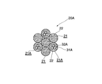
繊維裸ロープは,径が 3.5mmの6本の繊維ストランド20と,径が 3.5mmの1本の複合ストランド20Aとを,複合ストランド20Aを中心に配置して,撚りピッチ60mmで撚り合わせて,径が10mmに構成されている。繊維ストランド20は,径が 1.2mmの7束の繊維束21を,撚りピッチ24mmで撚り合わせて構成されている。複合ストランド20Aは,図2に示すように,径が 1.2mmの4束の繊維束21と,径が 1.2mmの3束の複合繊維束21Aとを,複合繊維束21Aが隣り合うことなく,各々の複合繊維束21Aの間に繊維束21を配置して,撚りピッチ24mmで撚り合わせて構成されている。
【0026】
繊維束21は,径が12μmの数千本のアラミド系繊維のフィラメント22を束ねたものである。また,複合繊維束21Aは,1本の寿命検知用スチールワイヤ撚り線31Aが,中央の位置で,数千本のフィラメント22とともに束ねられて構成されている。スチールワイヤ撚り線31Aは,径が 0.365mmの3本のスチールワイヤ32Aを,撚りピッチ7mm(繊維裸ロープの撚りピッチ60mm,複合ストランドの撚りピッチ24mmよりも小さく)で,撚り合わせて構成されている。スチールワイヤ撚り線31Aは,繊維よりも伸びやすくするために複合ストランド20Aの撚りピッチ以下の撚りピッチで撚り合わされている。
【0027】
動索用繊維ロープ1の外周には,その全周囲にわたって,厚さ1mmでポリエチレン被覆が施され,被覆層4が形成されている。たとえば,被覆層4は,繊維裸ロープを筒状体に挿通して移動させながらこの筒状体内に加熱して軟化(流動化)させたポリエチレンを圧入してポリエチレンを繊維裸ロープの外周面に付着させ,繊維裸ロープの周囲に付着したポリエチレンの外形をダイス等に通して整え,冷却させることにより形成される。合成樹脂被覆層4により,動索用繊維ロープ1の摩擦による外傷または腐食を防ぐことができる。
【0028】
表1に,図1に示す第1実施例の動索用繊維ロープ1および従来のワイヤロープ(従来例)についての疲労試験結果を示す。従来例のワイヤロープは,中心に配置されたポリプロピレンの繊維束の周りに鋼製のストランドを撚り合わしたもので,6×Fi(29)の構造を有する。従来例のワイヤロープの径は10mm,撚りピッチは60mmである。
【0029】
【表1】
疲労試験は,図4に示すように,被試験ロープ(第1実施例の動索用繊維ロープ1または従来例のワイヤロープ)を駆動シーブ10に掛け,さらに2つの同じ径の試験シーブ12,13に掛け(S曲げして),テンションシーブ11に掛ける。テンションシーブ11に重り14を吊下げることにより被試験ロープに張力を与える。駆動シーブ10は,5サイクル/分で往復回転する。1サイクルのストロークは,3000mmである。疲労試験は,安全率6で,試験シーブ12,13の径Dと被試験ロープの径dとの比D/dが10,16,および20の場合について行った。動索用繊維ロープ1については,動索用繊維ロープ1内に入れられたスチールワイヤ撚り線31Aが断線するまでの総ストロークと動索用繊維ロープ1が破断するまでの総ストローク(1サイクルのストロークとサイクル数との積)とを測定した。また従来例のワイヤロープについては,ワイヤロープが破断するまでの総ストロークを測定した。
【0031】
表1の寿命比は,D/d=10の場合において従来例のワイヤロープが破断するまでの総ストロークを基準(すなわち1)として表わしている。すなわち,動索用繊維ロープ1内に入れられたスチールワイヤ撚り線31Aが断線するまでの総ストローク,動索用繊維ロープ1が破断するまでの総ストローク,または従来例のワイヤロープが破断するまでの総ストロークを,D/d=10の場合において従来例のワイヤロープが破断するまでの総ストロークで除算して,小数点以下を切り捨てて,整数値としてそれぞれの寿命比を求めた。疲労試験の結果,動索用繊維ロープ1内に入れられたスチールワイヤ撚り線31Aの断線検知までの総ストロークは,D/dが10,16,および20のいずれの場合も,従来のワイヤロープの破断までの総ストロークの2倍以上であった(寿命比はそれぞれ2,8および12)。また動索用繊維ロープ1の破断までの総ストロークは,D/dが10,16,および20のいずれの場合においても,従来例のワイヤロープの破断までの総ストロークの4倍以上であった(寿命比はそれぞれ4,16および24)。したがって,動索用繊維ロープ1は,ワイヤロープよりも疲労強度が高いことが確認できた。また,スチールワイヤ撚り線31Aの断線検知までの総ストロークの方が,動索用繊維ロープ1の破断までの総ストロークよりも小さいことが確認できた。すなわち,スチールワイヤ撚り線31Aの断線は,動索用繊維ロープ1が破断するよりも早期に生じるので,スチールワイヤ撚り線31Aの断線を検知することにより,動索用繊維ロープ1が破断する前にその交換時期を判断することができる。
【0032】
第1実施例の動索用繊維ロープにおいては,寿命検知用スチールワイヤ撚り線31Aが動索用繊維ロープ1の一端から他端まで連続的に複合繊維束21A内に設けられているので,損傷検出器等の機器を使用してスチールワイヤ撚り線31Aの損傷等による断線の有無および断線の箇所を検出することができる。スチールワイヤ撚り線31Aの断線が検出されたときには,動索用繊維ロープ1にも損傷等が生じている,劣化している,または損傷等が生じるであろう,劣化の時期にきているであろう,したがって動索用繊維ロープ1には寿命がきており,交換すべき時期であると予測できる。これにより,動索用繊維ロープ1の交換時期を誤ることなく,安全性を確保できる。
【0033】
複合ストランドは,図3に示す複合ストランド20Bのように,繊維束を用いることなく複数束の複合繊維束21Aのみを撚り合わせて構成してもよい。
【0034】
複合繊維束は,寿命検知用スチールワイヤ撚り線を用いるものではなく,一または複数本の単線の寿命検知用スチールワイヤと,数千本のフィラメントとを束ね合わて構成したものであってもよい。寿命検知用スチールワイヤを繊維よりも伸びやすくするために,その外周面に,長手方向に沿って,複合ストランドの撚りピッチよりも短いピッチで,凹溝または凸条を螺旋状に形成する(クリンプ加工)。
【0035】
第1実施例の動索用繊維ロープの変形例を図5および図6に示す。図5は動索用繊維ロープの断面図である。図6は動索用繊維ロープの構成要素である複合ストランドの拡大断面図である。第1実施例の動索用繊維ロープ1においては,1本の複合ストランド20Aを中心に配置して6本の繊維ストランド20を撚り合わせて繊維裸ロープが構成されているのに対し,動索用繊維ロープ1Bの繊維裸ロープは,1本の繊維ストランド20を中心に配置して,その周りに5本の繊維ストランド20と1本の複合ストランド20Cとを撚り合わせて構成されている。複合ストランド20Cは,1束の繊維束21を中心に配置して,3束の繊維束21と3束の複合繊維束21Bとがその周りに撚り合わされて構成されている。複合繊維束21Bは,2本の単線の寿命検知用スチールワイヤ32Bが互いに間隔をあけてフィラメント22とともに束ね合わされている。2本の単線の寿命検知用スチールワイヤ32Bの外側周囲には,長手方向に沿って螺旋状にクリンプが形成されている。このように複合ストランド20Cは,繊維裸ロープにおいていずれの位置に配置してもよい。また,スチールワイヤの本数および配置する位置も動索用ロープの損傷,劣化等により動索用繊維ロープを交換する時期に断線が検知されるように定めればよい。
【0036】
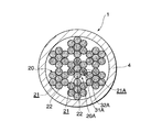
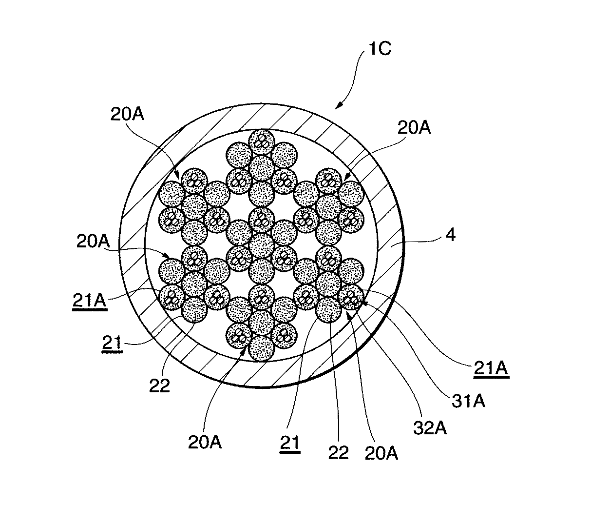
図7は,第1実施例の動索用繊維ロープの他の変形例の断面図である。図1に示す第1実施例の動索用繊維ロープ1においては,1本の複合ストランド20Aを中心に配置して6本の繊維ストランド20を撚り合わせて繊維裸ロープが構成されているのに対し,図7に示す動索用繊維ロープ1Cの繊維裸ロープは,1本の複合ストランド20Aを中心に配置してその周りに6本の複合ストランド20Aを撚り合わせて構成されている。すなわち,繊維ストランドを用いることなく複合ストランド20Aのみを撚り合わせて繊維裸ロープが構成されている。複合ストランド20Aは,1束の繊維束21を中心に配置して,3束の繊維束21と3束の複合繊維束21Aとがその周りに撚り合わされて構成されている。複合繊維束21Aは1本の寿命検知用スチールワイヤ撚り線31Aを中央に配置して数千本のフィラメント22とともに束ね合わされて構成されている。スチールワイヤ撚り線31Aは,3本のスチールワイヤ32Aを,複合ストランド20Aの撚りピッチよりも短いピッチで,撚り合わせて構成されている。
【0037】
図8は,第2実施例の動索用繊維ロープの断面図である。動索用繊維ロープ1Dの繊維裸ロープは,1本の繊維ストランド20を中心に配置して,その周りに5本の繊維ストランド20と1本の複合ストランド20Aとを撚り合わせ,さらにその外側には11本の繊維ストランド20と1本の複合ストランド20Aとを撚り合わせて構成されている。複合ストランド20Aは,1束の繊維束21を中心に配置して,3束の繊維束21と3束の複合繊維束21Aとがその周りに撚り合わされて構成されている。複合繊維束21Aは,1本の寿命検知用スチールワイヤ撚り線31Aを中央に配置して数千本のフィラメント22とともに束ねられて構成されている。スチールワイヤ撚り線31Aは,3本のスチールワイヤ32Aを,複合ストランド20Aの撚りピッチよりも小さい撚りピッチで,撚り合わせて構成されている。動索用繊維ロープ1Dの繊維裸ロープは,1+6+12の三層構造からなり,繊維裸ロープの第2層目と3層目とにそれぞれ複合ストランド20Aが1本ずつ配置されている。このように動索用繊維ロープを構成する繊維裸ロープの構造は,要求される径,強度等に応じてさまざまな形態とすることができる。
【0038】
図9は,第3実施例の動索用繊維ロープの断面図である。第3実施例の動索用繊維ロープ1Eの繊維裸ロープは,1束の繊維束21を中心に配置して,その周りに3束の繊維束21と3束の複合繊維束21Aとを撚り合わせて構成されている。すなわち,繊維裸ロープは複合ストランド20Aである。複合繊維束21Aは,1本の寿命検知用スチールワイヤ撚り線31Aを中央に配置して数千本のフィラメント22とともに束ね合わされて構成されている。スチールワイヤ撚り線31Aは,3本のスチールワイヤ32Aを,複合ストランド20Aの撚りピッチよりも短いピッチで,撚り合わせて構成されている。第1,2実施例の動索用繊維ロープ1,1B,1Cおよび1Dが比較的大径の動索用繊維ロープに適しているのに対して,第3実施例の動索用繊維ロープ1Eは,比較的小径の動索用繊維ロープに適している。
【0039】
図10は,第3実施例の動索用繊維ロープの変形例の断面図である。図9に示す動索用繊維ロープ1Eにおいては1束の繊維束21を中心に配置してその周りに3束の繊維束21と3束の複合繊維束21Aとを撚り合わせて繊維裸ロープ(複合ストランド20A)が構成されているのに対して,図10に示す動索用繊維ロープ1Fの繊維裸ロープは,1束の複合繊維束21Aを中心に配置して,その周りに6束の複合繊維束21Aを撚り合わせて構成されている。すなわち,繊維裸ロープは複合ストランド20Bであり,複合ストランド20Bは繊維束を用いることなく複合繊維束21Aのみを撚り合わせて構成されている。複合繊維束21Aは,1本の寿命検知用スチールワイヤ撚り線31Aを中央に配置して数千本のフィラメント22とともに束ね合わされて構成されている。スチールワイヤ撚り線31Aは,3本のスチールワイヤ32Aを,複合ストランド20Aの撚りピッチよりも短いピッチで,撚り合わされて構成されている。
【図面の簡単な説明】
【図1】第1実施例の動索用繊維ロープの断面図である。
【図2】第1実施例の動索用繊維ロープの構成要素である複合ストランドの拡大断面図である。
【図3】複合ストランドの変形例の拡大断面図である。
【図4】疲労試験装置の構成を示す。
【図5】第1実施例の変形例の動索用繊維ロープの断面図である。
【図6】第1実施例の変形例の動索用繊維ロープの構成要素である複合ストランドの拡大断面図である。
【図7】第1実施例の動索用繊維ロープの他の変形例の断面図である。
【図8】第2実施例の動索用繊維ロープの断面図である。
【図9】第3実施例の動索用繊維ロープの断面図である。
【図10】第3実施例の動索用繊維ロープの変形例の断面図である。
【符号の説明】
1,1B,1C,1D,1E,1F 動索用繊維ロープ
4 被覆層
20 繊維ストランド
20A,20B,20C 複合ストランド
21 繊維束
21A,21B 複合繊維束
22 繊維フィラメント
31A 寿命検知用スチールワイヤ撚り線
32B 寿命検知用スチールワイヤ[0001]
【Technical field】
The present invention relates to a moving rope for a crane, a moving rope for an elevator, and a fiber rope for a moving rope used for other purposes.
[0002]
[Prior art]
A wire rope is used as the moving cable. Generally, a wire rope used for a moving cord has a structure in which a fiber bundle is arranged at the center and steel strands are twisted around the fiber bundle. The fiber bundle supports the strands twisted around it to maintain the shape of the wire rope, and replenishes the strands with grease to prevent strand damage and corrosion. Since the steel strand is the main component of the wire rope, it is difficult to reduce the weight.
[0003]
Fiber ropes, on the other hand, are lighter and more flexible than steel wire ropes of the same diameter, and have fatigue strength against repeated pulling and bending, but it is difficult to detect damage or diagnose deterioration. It is difficult to use as a moving cord.
[0004]
DISCLOSURE OF THE INVENTION
It is an object of the present invention to provide a moving rope fiber rope that can easily detect damage or diagnose deterioration.
[0005]
The fiber rope for moving cords according to the first invention comprises at least one composite strand and at least one fiber strand twisted to form a bare fiber rope, and a coating layer so as to cover the outer periphery of the bare fiber rope The composite strand is formed by twisting at least one bundle of composite fiber bundles and at least one bundle of fiber bundles, or by twisting a plurality of bundles of composite fiber bundles. A life detection metal wire or a life detection metal stranded wire formed by twisting a plurality of metal wires, which is larger than the fiber, is included.
[0006]
The number and arrangement of the composite strands and the fiber strands that are twisted together to form the bare fiber rope are determined according to the size of the rope for the rope, the required strength, and the like. It is sufficient that at least one composite strand and at least one fiber strand are included. The twisting method, shape, and diameter of the composite strand and fiber strand are determined according to the shape, diameter, required tensile strength, bending strength, and the like of the moving rope.
[0007]
The coating layer is formed to cover the outer periphery of the bare fiber rope. The synthetic resin is welded or adhered to the outer periphery of the bare fiber rope. The synthetic resin tape is wound around the outer periphery of the bare fiber rope. It can be formed by a method of braiding with fibers or combining them. Furthermore, the thickness of the coating layer is determined according to the size of the diameter of the moving rope, the required strength of the coating layer, and the like. The coating layer can prevent trauma or corrosion due to friction of the moving rope.
[0008]
The composite strand is constituted by twisting at least one bundle of composite fiber bundles and at least one bundle of fiber bundles, or twisting a plurality of bundles of composite fiber bundles. The number and arrangement of the composite fiber bundle and fiber bundle to be twisted are determined according to the required diameter, strength, and the like.
[0009]
The fiber strand is formed by twisting a plurality of fiber bundles. The fiber bundle is a bundle of a large number of filaments (fibers) such as synthetic fibers such as aramid fibers or natural fibers.
[0010]
The twist, shape and diameter of the composite fiber bundles or fiber bundles that make up these composite strands or fiber strands are determined according to the shape, diameter, required tension, and bending of the rope for the rope. It is determined according to strength.
[0011]
The composite fiber bundle which is a component of the composite strand has a life detection metal wire (one or more) or a life detection metal strand (one or more) formed by twisting a plurality of metal wires. , Bundled together with a large number of filaments (fibers) such as synthetic fibers such as aramid fibers or natural fibers. The life detection metal wire or the life detection metal stranded wire may be located anywhere (in the center or the periphery) of a large number of filaments.
[0012]
The life detection metal wire is a conductive metal wire including a steel wire. The life detection metal stranded wire is formed by twisting a plurality of metal wires. The material, cross-sectional shape, diameter, and number of metal wires constituting the life detection metal strand or the life detection metal stranded wire are determined by the rope cable rope being damaged or deteriorated. It is set so that the wire breaks at the time of replacement (the time when the life of the rope for ropes has reached the end of its life) or has such a strength that breakage is detected.
[0013]
In any case, the metal wire for life detection or the metal strand for life detection is a composite fiber in a state where it is continuously connected without being disconnected from one end to the other end of the fiber rope for moving cable (without being disconnected). Provided in the bundle.
[0014]
The life detection metal wire or the life detection metal strand does not need to bear a load (mainly tensile load) applied to the moving fiber rope. Rather, it is desirable that the life detection metal wire or the life detection metal strand does not bear the load applied to the moving rope fiber rope. For this reason, the life detection metal wire or the life detection metal stranded wire is assumed to have a larger elongation than the fiber bearing the load (a fiber bundle, a composite fiber bundle, a fiber strand or a composite strand). Of course, it is a premise that the life detection metal wire or the life detection metal stranded wire bends (is easily bent) together with the moving fiber rope.
[0015]
In order to make the metal wire for life detection larger than the fiber, in one embodiment, a groove or a ridge is formed in a spiral shape along the longitudinal direction on the outer peripheral surface of the metal wire for life detection ( Crimping). The life detection metal stranded wire can be easily stretched by twisting at a short twist pitch (preferably shorter than the twist pitch of the composite strand).
[0016]
As mentioned above, the fiber rope for moving cords is basically a fiber rope (in terms of the load bearing part), so it is lighter than the steel rope of the same diameter, has a smaller elastic modulus, There is fatigue strength. In other words, the fiber rope for moving cords is lightweight, easy to bend, and is not easily fatigued by repeated pulling and bending. Also, the fiber rope for moving rope contains one or more life detection metal wires or life detection metal strands along the longitudinal direction. 6-87861) can be used to easily detect the location of breakage due to damage or the like of the life detection metal wire or the life detection metal stranded wire. When a disconnection of a life detection metal wire or a life detection metal strand is detected, the fiber rope for the rope is also damaged, deteriorated, or damaged, etc. It is likely that it is time, so the fiber rope for the rope is at the end of its life and can be expected to be replaced. As a result, safety can be ensured without mistaken replacement timing of the moving rope rope.
[0017]
The fiber rope for moving cords according to the second invention comprises a bare fiber rope formed by twisting a plurality of composite strands, and a covering layer is formed so as to cover the outer periphery of the bare fiber rope. At least one bundle of composite fibers and at least one bundle of fiber bundles are twisted together, or a plurality of bundles of composite fiber bundles are twisted together. A metal wire for life detection or a metal strand for life detection formed by twisting a plurality of metal wires is included.
[0018]
The difference between the fiber rope for rope according to the second invention of the present application and the fiber rope for rope according to the first invention is that the fiber rope for rope according to the first invention is at least one composite strand and at least one fiber. In contrast to a strand, the moving rope fiber rope according to the second invention is that a bare fiber rope is formed by twisting a plurality of composite strands. The fiber rope for moving cords according to the second invention is composed of a plurality of composite strands, and the composite strand includes at least one composite fiber bundle. The composite fiber bundle contains a life detection metal wire (one or more) or a life detection metal strand (one or more), so a life detection metal wire or a life detection metal strand By detecting this disconnection, it becomes possible to easily detect damage or diagnosis of deterioration of the entire fiber rope for moving cords. Furthermore, since the main structure is a fiber rope, the weight can be reduced and the fatigue strength against bending and tension can be increased.
[0019]
According to a third aspect of the present invention, there is provided a moving rope fiber rope, wherein at least one bundle of composite fiber bundles and at least one bundle of fiber bundles are twisted together to form a composite strand. The formed composite fiber bundle includes a life detection metal wire having a greater elongation than the fiber or a life detection metal strand formed by twisting a plurality of metal wires.
[0020]
The moving rope rope according to the first or second invention includes a plurality of fiber strands or composite strands, and is suitable for a relatively large diameter moving rope rope. Since the fiber rope for ropes according to the invention includes one composite strand, it is suitable for a fiber rope for ropes having a relatively small diameter. The fiber rope for moving cords according to the third invention is composed of one composite strand, and the composite strand includes at least one composite fiber bundle. The composite fiber bundle contains a life detection metal wire (one or more) or a life detection metal strand (one or more), so a life detection metal wire or a life detection metal strand By detecting this disconnection, it becomes possible to easily detect damage or diagnosis of deterioration of the entire fiber rope for moving cords. Furthermore, since the main structure is a fiber rope, the weight can be reduced and the fatigue strength against bending and tension can be increased.
[0021]
According to a fourth aspect of the present invention, there is provided a moving rope fiber rope in which a plurality of bundles of composite fibers are twisted to form a composite strand, and a coating layer is formed on the outer periphery of the composite strand to cover the composite strand. Includes a life detection metal wire having a larger elongation than that of a fiber or a life detection metal strand formed by twisting a plurality of metal wires.
[0022]
The difference between the fiber rope for moving cords according to the fourth invention of the present application and the fiber rope for moving ropes according to the third invention is that a composite fiber bundle comprising at least one bundle of composite strands constituting the fiber rope for moving cords according to the third invention is provided. And at least one bundle of fiber bundles, the moving rope fiber rope according to the fourth invention is characterized in that one composite strand is formed by twisting a plurality of bundles of composite fiber bundles. The fiber rope for moving cords according to the fourth invention is composed of one composite strand, and all the composite strands are composed of a plurality of bundles of composite fibers. The composite fiber bundle contains a life detection metal wire (one or more) or a life detection metal strand (one or more), so a life detection metal wire or a life detection metal strand By detecting this disconnection, it becomes possible to easily detect damage or diagnosis of deterioration of the entire fiber rope for moving cords. Furthermore, since the main structure is a fiber rope, the weight can be reduced and the fatigue strength against bending and tension can be increased.
[0023]
[Explanation of Examples]
The fiber rope for moving cords according to the first embodiment is shown in FIGS. FIG. 1 is a cross-sectional view of a moving rope fiber rope, and FIG. 2 is an enlarged cross-sectional view of a composite strand that is a constituent element of the moving rope rope.
[0024]
The fiber rope 1 for moving ropes is composed of one
[0025]
The bare fiber rope is composed of 6
[0026]
The
[0027]
The outer periphery of the moving rope 1 is coated with a polyethylene coating with a thickness of 1 mm over the entire circumference to form a
[0028]
Table 1 shows the fatigue test results for the fiber rope 1 for moving cords of the first embodiment shown in FIG. 1 and the conventional wire rope (conventional example). The wire rope of the conventional example is obtained by twisting steel strands around a polypropylene fiber bundle arranged in the center, and has a structure of 6 × Fi (29). The diameter of the conventional wire rope is 10 mm, and the twist pitch is 60 mm.
[0029]
[Table 1]
In the fatigue test, as shown in FIG. 4, the rope to be tested (the fiber rope 1 for moving rope of the first embodiment or the wire rope of the conventional example) is hung on the
[0031]
The life ratios in Table 1 are expressed with reference to the total stroke until the wire rope of the conventional example breaks when D / d = 10 (ie, 1). That is, the total stroke until the steel wire stranded
[0032]
In the fiber rope for moving cords according to the first embodiment, the steel wire stranded
[0033]
The composite strand may be formed by twisting only a plurality of bundles of
[0034]
The composite fiber bundle may not be formed of a steel wire stranded wire for life detection, but may be constituted by bundling one or more single wire life detection steel wires and thousands of filaments. . In order to make the steel wire for life detection easier to stretch than the fiber, a concave groove or a ridge is formed in a spiral shape on the outer peripheral surface along the longitudinal direction at a pitch shorter than the twist pitch of the composite strand (crimp processing).
[0035]
The modification of the fiber rope for a rope of 1st Example is shown in FIG. 5 and FIG. FIG. 5 is a sectional view of a fiber rope for moving cords. FIG. 6 is an enlarged cross-sectional view of a composite strand that is a constituent element of a moving rope fiber rope. In the fiber rope 1 for moving cords according to the first embodiment, the bare fiber rope is constructed by arranging six
[0036]
FIG. 7 is a sectional view of another modification of the moving rope fiber rope of the first embodiment. In the fiber rope 1 for moving cords of the first embodiment shown in FIG. 1, a bare fiber rope is formed by arranging six
[0037]
FIG. 8 is a cross-sectional view of the fiber rope for moving cords of the second embodiment. The bare rope of the
[0038]
FIG. 9 is a cross-sectional view of the fiber rope for moving cords of the third embodiment. The bare fiber rope of the
[0039]
FIG. 10 is a sectional view of a modification of the moving rope fiber rope of the third embodiment. In the
[Brief description of the drawings]
FIG. 1 is a cross-sectional view of a fiber rope for moving cords according to a first embodiment.
FIG. 2 is an enlarged cross-sectional view of a composite strand that is a component of the moving rope fiber rope of the first embodiment.
FIG. 3 is an enlarged cross-sectional view of a modified example of a composite strand.
FIG. 4 shows a configuration of a fatigue test apparatus.
FIG. 5 is a cross-sectional view of a moving fiber rope according to a modification of the first embodiment.
FIG. 6 is an enlarged cross-sectional view of a composite strand that is a component of a moving rope fiber rope according to a modification of the first embodiment.
FIG. 7 is a cross-sectional view of another modification of the moving rope fiber rope of the first embodiment.
FIG. 8 is a cross-sectional view of a moving rope fiber rope according to a second embodiment.
FIG. 9 is a sectional view of a moving rope fiber rope according to a third embodiment.
FIG. 10 is a cross-sectional view of a modification of the moving rope fiber rope of the third embodiment.
[Explanation of symbols]
1,1B, 1C, 1D, 1E, 1F Fiber rope for moving
20 fiber strands
20A, 20B, 20C composite strand
21 Fiber bundle
21A, 21B Composite fiber bundle
22 Fiber filament
31A Steel wire stranded wire for life detection
32B Steel wire for life detection
Claims (4)
上記複合ストランドは,少なくとも一束の複合繊維束と少なくとも一束の繊維束とが撚り合わされて,または複数束の複合繊維束が撚り合わされて構成され,
上記複合繊維束には,外周面にクリンプ加工が施された寿命検知用金属線,または複数本の金属線が上記複合ストランドの撚りピッチよりも短い撚りピッチで撚り合わされてなる寿命検知用金属撚り線が含まれている,動索用繊維ロープ。At least one composite strand and at least one fiber strand are twisted together to form a bare fiber rope, and a covering layer is formed to cover the outer periphery of the bare fiber rope.
The composite strand is formed by twisting at least one bundle of composite fiber bundles and at least one bundle of fiber bundles, or twisting a plurality of bundles of composite fiber bundles,
The composite fiber bundle includes a life detection metal wire crimped on the outer peripheral surface or a life detection metal twist formed by twisting a plurality of metal wires at a twist pitch shorter than the twist pitch of the composite strand. A fiber rope for moving cords that contains wires.
上記複合ストランドは,少なくとも一束の複合繊維束と少なくとも一束の繊維束とが撚り合わされて,または複数束の複合繊維束が撚り合わされて構成され,
上記複合繊維束には,外周面にクリンプ加工が施された寿命検知用金属線,または複数本の金属線が上記複合ストランドの撚りピッチよりも短い撚りピッチで撚り合わされてなる寿命検知用金属撚り線が含まれている,動索用繊維ロープ。A plurality of composite strands are twisted together to form a bare fiber rope, and a coating layer is formed to cover the outer periphery of the bare fiber rope.
The composite strand is formed by twisting at least one bundle of composite fiber bundles and at least one bundle of fiber bundles, or twisting a plurality of bundles of composite fiber bundles,
The composite fiber bundle includes a life detection metal wire crimped on the outer peripheral surface or a life detection metal twist formed by twisting a plurality of metal wires at a twist pitch shorter than the twist pitch of the composite strand. A fiber rope for moving cords that contains wires.
上記複合繊維束には,外周面にクリンプ加工が施された寿命検知用金属線,または複数本の金属線が上記複合ストランドの撚りピッチよりも短い撚りピッチで撚り合わされてなる寿命検知用金属撚り線がが含まれている,動索用繊維ロープ。A composite strand is formed by twisting at least one bundle of composite fibers and at least one bundle of fibers, and a coating layer is formed so as to cover the outer periphery of the composite strand.
The composite fiber bundle includes a life detection metal wire crimped on the outer peripheral surface or a life detection metal twist formed by twisting a plurality of metal wires at a twist pitch shorter than the twist pitch of the composite strand. A fiber rope for ropes that contains wires.
上記複合繊維束には,外周面にクリンプ加工が施された寿命検知用金属線,または複数本の金属線が上記複合ストランドの撚りピッチよりも短い撚りピッチで撚り合わされてなる寿命検知用金属撚り線が含まれている,動索用繊維ロープ。A composite strand is formed by twisting a plurality of bundles of composite fibers, and a coating layer is formed so as to cover the outer periphery of the composite strand.
The composite fiber bundle includes a life detection metal wire crimped on the outer peripheral surface or a life detection metal twist formed by twisting a plurality of metal wires at a twist pitch shorter than the twist pitch of the composite strand. A fiber rope for moving cords that contains wires.
Priority Applications (1)
| Application Number | Priority Date | Filing Date | Title |
|---|---|---|---|
| JP2003094016A JP4092237B2 (en) | 2003-03-31 | 2003-03-31 | Fiber rope for rope |
Applications Claiming Priority (1)
| Application Number | Priority Date | Filing Date | Title |
|---|---|---|---|
| JP2003094016A JP4092237B2 (en) | 2003-03-31 | 2003-03-31 | Fiber rope for rope |
Publications (2)
| Publication Number | Publication Date |
|---|---|
| JP2004300609A JP2004300609A (en) | 2004-10-28 |
| JP4092237B2 true JP4092237B2 (en) | 2008-05-28 |
Family
ID=33406676
Family Applications (1)
| Application Number | Title | Priority Date | Filing Date |
|---|---|---|---|
| JP2003094016A Expired - Fee Related JP4092237B2 (en) | 2003-03-31 | 2003-03-31 | Fiber rope for rope |
Country Status (1)
| Country | Link |
|---|---|
| JP (1) | JP4092237B2 (en) |
Families Citing this family (28)
| Publication number | Priority date | Publication date | Assignee | Title |
|---|---|---|---|---|
| US7681934B2 (en) | 2004-11-02 | 2010-03-23 | Toray International, Inc. | Fiber sling and method for evaluating its performance |
| JP2010254394A (en) * | 2009-04-22 | 2010-11-11 | Mitsubishi Electric Building Techno Service Co Ltd | Wire rope and method for inspecting life of the wire rope |
| WO2012142107A1 (en) | 2011-04-12 | 2012-10-18 | Ticona Llc | Continious fiber reinforced thermoplastic rod and pultrusion method for its manufacture |
| KR20140027252A (en) | 2011-04-12 | 2014-03-06 | 티코나 엘엘씨 | Composite core for electrical transmission cables |
| AU2012242930B2 (en) | 2011-04-12 | 2016-03-31 | Southwire Company | Electrical transmission cables with composite cores |
| BR112013025588A2 (en) | 2011-04-12 | 2016-12-27 | Ticona Llc | umbilical cable for use in underwater applications |
| US9346222B2 (en) | 2011-04-12 | 2016-05-24 | Ticona Llc | Die and method for impregnating fiber rovings |
| CN103547440B (en) | 2011-04-12 | 2017-03-29 | 提克纳有限责任公司 | For impregnating the mould impregnation section and method of fiber roving |
| US9623437B2 (en) | 2011-04-29 | 2017-04-18 | Ticona Llc | Die with flow diffusing gate passage and method for impregnating same fiber rovings |
| CA2775445C (en) | 2011-04-29 | 2019-04-09 | Ticona Llc | Die and method for impregnating fiber rovings |
| CA2775442C (en) | 2011-04-29 | 2019-01-08 | Ticona Llc | Impregnation section with upstream surface and method for impregnating fiber rovings |
| US10336016B2 (en) | 2011-07-22 | 2019-07-02 | Ticona Llc | Extruder and method for producing high fiber density resin structures |
| WO2013086259A1 (en) | 2011-12-09 | 2013-06-13 | Ticona Llc | Die and method for impregnating fiber rovings |
| CN108192278B (en) | 2011-12-09 | 2020-12-29 | 提克纳有限责任公司 | Asymmetric fiber reinforced polymer tapes |
| WO2013086269A1 (en) | 2011-12-09 | 2013-06-13 | Ticona Llc | Impregnation section of die for impregnating fiber rovings |
| US9283708B2 (en) | 2011-12-09 | 2016-03-15 | Ticona Llc | Impregnation section for impregnating fiber rovings |
| JP2015505752A (en) | 2011-12-09 | 2015-02-26 | ティコナ・エルエルシー | Impregnation section and die for impregnating fiber roving |
| JP2013142202A (en) * | 2012-01-06 | 2013-07-22 | Endo Kogyo Kk | Wire rope and spring balancer |
| US9410644B2 (en) | 2012-06-15 | 2016-08-09 | Ticona Llc | Subsea pipe section with reinforcement layer |
| JP2015532716A (en) * | 2012-09-04 | 2015-11-12 | テイジン・アラミド・ビー.ブイ. | Nondestructive testing method for synthetic fiber rope and rope suitable for use in the method |
| DE102013103118A1 (en) * | 2013-03-27 | 2014-10-02 | Pfeifer Drako Drahtseilwerk Gmbh & Co. Kg | Multistrand steel wire rope with a multi-core fiber core |
| EP3265597A1 (en) * | 2015-03-02 | 2018-01-10 | DSM IP Assets B.V. | Indicator yarn construction |
| JP6969973B2 (en) * | 2017-10-19 | 2021-11-24 | 東京製綱株式会社 | Fiber reinforced plastic striatum with damage detection function |
| CN107881819A (en) * | 2017-11-18 | 2018-04-06 | 浙江海轮绳网有限公司 | A kind of deep-sea engineering hawser |
| CN112064383A (en) * | 2020-07-20 | 2020-12-11 | 抚州大力实业发展有限公司 | Improved composite material rope structure |
| CN113327701B (en) * | 2021-06-08 | 2023-01-03 | 广东伟坤翔电力建设有限公司 | High-strength flexible fiber core power transmission stranded wire |
| CN114875697A (en) * | 2022-06-01 | 2022-08-09 | 武钢维尔卡钢绳制品有限公司 | Composite core, steel wire rope and manufacturing method thereof |
| JP7279250B1 (en) * | 2022-10-31 | 2023-05-22 | 東京製綱株式会社 | Fiber-reinforced resin cable and wire with damage detection function |
-
2003
- 2003-03-31 JP JP2003094016A patent/JP4092237B2/en not_active Expired - Fee Related
Also Published As
| Publication number | Publication date |
|---|---|
| JP2004300609A (en) | 2004-10-28 |
Similar Documents
| Publication | Publication Date | Title |
|---|---|---|
| JP4092237B2 (en) | Fiber rope for rope | |
| EP2573257B1 (en) | Hybrid rope and process for producing same | |
| AU610043B2 (en) | Rope with fiber core and method of forming same | |
| KR101491907B1 (en) | Hybrid core rope | |
| US8632432B2 (en) | Flat-belt-like supporting and drive means with tensile carriers | |
| EP1920092B1 (en) | Wire rope incorporating fluoropolymer fiber | |
| US7086217B2 (en) | Rope of synthetic fiber with reinforcement element for frictionally engaged power transmission and rope of synthetic fiber with reinforcement element for positively engaged power transmission | |
| JP7113004B2 (en) | hoist rope | |
| JP6760824B2 (en) | High strength wire rope | |
| GB2036825A (en) | Synthetic Fibre Rope | |
| JPH10140490A (en) | Wire rope having fiber core | |
| JP4034629B2 (en) | Hybrid rope | |
| WO2020230171A1 (en) | Elongation and heat indicating synthetic fibre rope | |
| JP2007177362A (en) | Steel cord for reinforcing rubber product | |
| KR102486074B1 (en) | elevator rope | |
| JP2000130427A (en) | Inner cord for control cable | |
| EP1329413B1 (en) | Hoisting rope | |
| JP7412126B2 (en) | Flexible insulated wire | |
| JP7486300B2 (en) | Bend-resistant insulated wire | |
| JP7412125B2 (en) | Flexible insulated wire | |
| JPH0874190A (en) | Wire rope having inner corrosion resistance and inner abrasion resistance | |
| US20230407561A1 (en) | Cable, Strand, and Method and Device for Producing a Cable and a Strand | |
| JP2862543B2 (en) | Composite twist type tensile strength element | |
| JPH05295684A (en) | Wire rope | |
| CN113215720A (en) | Synthetic fiber cable |
Legal Events
| Date | Code | Title | Description |
|---|---|---|---|
| A621 | Written request for application examination |
Free format text: JAPANESE INTERMEDIATE CODE: A621 Effective date: 20051021 |
|
| A977 | Report on retrieval |
Free format text: JAPANESE INTERMEDIATE CODE: A971007 Effective date: 20071130 |
|
| A131 | Notification of reasons for refusal |
Free format text: JAPANESE INTERMEDIATE CODE: A131 Effective date: 20071211 |
|
| A521 | Request for written amendment filed |
Free format text: JAPANESE INTERMEDIATE CODE: A523 Effective date: 20080201 |
|
| TRDD | Decision of grant or rejection written | ||
| A01 | Written decision to grant a patent or to grant a registration (utility model) |
Free format text: JAPANESE INTERMEDIATE CODE: A01 Effective date: 20080226 |
|
| A61 | First payment of annual fees (during grant procedure) |
Free format text: JAPANESE INTERMEDIATE CODE: A61 Effective date: 20080303 |
|
| R150 | Certificate of patent or registration of utility model |
Ref document number: 4092237 Country of ref document: JP Free format text: JAPANESE INTERMEDIATE CODE: R150 Free format text: JAPANESE INTERMEDIATE CODE: R150 |
|
| FPAY | Renewal fee payment (event date is renewal date of database) |
Free format text: PAYMENT UNTIL: 20110307 Year of fee payment: 3 |
|
| FPAY | Renewal fee payment (event date is renewal date of database) |
Free format text: PAYMENT UNTIL: 20110307 Year of fee payment: 3 |
|
| S531 | Written request for registration of change of domicile |
Free format text: JAPANESE INTERMEDIATE CODE: R313531 |
|
| FPAY | Renewal fee payment (event date is renewal date of database) |
Free format text: PAYMENT UNTIL: 20110307 Year of fee payment: 3 |
|
| R350 | Written notification of registration of transfer |
Free format text: JAPANESE INTERMEDIATE CODE: R350 |
|
| FPAY | Renewal fee payment (event date is renewal date of database) |
Free format text: PAYMENT UNTIL: 20140307 Year of fee payment: 6 |
|
| R250 | Receipt of annual fees |
Free format text: JAPANESE INTERMEDIATE CODE: R250 |
|
| R250 | Receipt of annual fees |
Free format text: JAPANESE INTERMEDIATE CODE: R250 |
|
| R250 | Receipt of annual fees |
Free format text: JAPANESE INTERMEDIATE CODE: R250 |
|
| R250 | Receipt of annual fees |
Free format text: JAPANESE INTERMEDIATE CODE: R250 |
|
| R250 | Receipt of annual fees |
Free format text: JAPANESE INTERMEDIATE CODE: R250 |
|
| R250 | Receipt of annual fees |
Free format text: JAPANESE INTERMEDIATE CODE: R250 |
|
| R250 | Receipt of annual fees |
Free format text: JAPANESE INTERMEDIATE CODE: R250 |
|
| R250 | Receipt of annual fees |
Free format text: JAPANESE INTERMEDIATE CODE: R250 |
|
| R250 | Receipt of annual fees |
Free format text: JAPANESE INTERMEDIATE CODE: R250 |
|
| R250 | Receipt of annual fees |
Free format text: JAPANESE INTERMEDIATE CODE: R250 |
|
| LAPS | Cancellation because of no payment of annual fees |