JP4089134B2 - Axis number detection device, vehicle type identification device, and toll collection system - Google Patents
Axis number detection device, vehicle type identification device, and toll collection system Download PDFInfo
- Publication number
- JP4089134B2 JP4089134B2 JP2000167626A JP2000167626A JP4089134B2 JP 4089134 B2 JP4089134 B2 JP 4089134B2 JP 2000167626 A JP2000167626 A JP 2000167626A JP 2000167626 A JP2000167626 A JP 2000167626A JP 4089134 B2 JP4089134 B2 JP 4089134B2
- Authority
- JP
- Japan
- Prior art keywords
- vehicle
- axis
- sensor
- axes
- output
- Prior art date
- Legal status (The legal status is an assumption and is not a legal conclusion. Google has not performed a legal analysis and makes no representation as to the accuracy of the status listed.)
- Expired - Lifetime
Links
Images


Landscapes
- Devices For Checking Fares Or Tickets At Control Points (AREA)
- Traffic Control Systems (AREA)
Abstract
Description
【0001】
【発明の属する技術分野】
この発明は、道路交通において、道路に埋設したセンサにより、車両の軸数を検知する軸数検知装置、およびその軸数検知装置を用いて車種判別を行い、車載機を搭載した車両との間で通信を行って料金を収受する技術に関するものである。
【0002】
【従来の技術】
近年、世界的に道路交通システムの高度化(高度道路交通システム:Intelligent Transport System、以下ITSと呼ぶ)に関する開発機運が高まっている。日本においても、1995年2月に政府の「高度情報通信社会推進に向けた基本方針」により、ITSの推進が決定され、これに基づいて同年8月に「道路・交通・車両分野における情報化実施指針」が打ち出され、その中で11の推進施策と9の開発分野が示されている。ここで、9つの開発分野とは、ナビゲーションの高度化、自動料金収受システム、安全運転の支援、交通管理の最適化、道路管理の効率化、公共交通の支援、商用車の効率化、歩行者等の支援および緊急車両の運行支援)が示されている。
【0003】
また、日本経済新聞(1998‐8‐28夕刊)の「初の料金自動徴収首都圏高速に登場」にあるように、車両に搭載した車載器と路側に設置した路側アンテナとの間で通信することによって通行料金を自動的に収受するノンストップ自動料金収受システム(Electronic Toll Collection以下ETCと呼ぶ)の開発も推進されている。ここで、ETCの基本構成を図10に示す。図10において1は道路、2は車両、3は料金所の屋根(図示せず)などにとりつけられ、路側機(図示せず)に接続された路側アンテナ、4は車載器であり、例えば図示のように車両2のバックミラーの窓ガラス側に固定される。また、6は料金所情報、7は車載器情報、8は車両2の前輪、9は車両2の後輪である。このような構成において車載器4を搭載した車両2が路側アンテナ3の通信領域に到達すると、路側アンテナ3と車載器4との間で無線による通信が行われ、車載器4からは、所有者情報、料金の引き落とし銀行口座、軸数情報、料金車種情報などの車載器情報7が路側アンテナ3側に送信される。一方、路側アンテナ3を介して得られた車載器情報7に基づいて路側機で通行料金が計算され、この通行料金の情報は路側アンテナ3を介して車載器4に送信される。また、通過日時などの料金所情報6が路側アンテナ3から車載器4に送信される。この双方向通信によって自動的に通行料金が課金される。
車載器情報7には、上記の所有者の情報、料金の引き落とし銀行口座などの他にその車両の軸数データ(図10では、前輪8と後輪9から構成されるので軸数は2つ)を含む料金車種情報を通信データとして使えるよう、車載器の記憶装置に予め登録される。
【0004】
一方、有料道路では、車両の種別により、徴収される通行料金が異なり、この車両の種別を決定する要素は、車長、車幅、軸数、車高、牽引の有無等である。例えば、都市高速道路では、均一料金方式が主として用いられており、普通自動車と大型車で料金が異なる。また、都市間高速道路では、入口発券出口収受方式が主として用いられ、軽自動車、普通車、中型車、大型車、特大車に分かれた料金車種体系が適用されている。また、牽引車の場合には、普通車が牽引する時は一段上位の中型車の料金が適用される等、一段上位の料金車種が適用される。
ETCにおいては、路上に設置された軸数検知器によって路側アンテナとの通信領域に進入する通行車両の軸数が計測され、車種判別装置(図示せず)によってこの計測された軸数と予め設定された軸数と、車種との対応関係を規定する情報とに基づいて通行車両の車種判別が行われ、路側機にこの車種判別の情報が出力されて、路側機ではこの車種判別情報を通行車両の履歴データとして記憶する。また、軸数比較器(図示せず)において、路側アンテナ3と車載器4との通信で得られた料金車種情報中の軸数データ(あるいは車種情報)と、上記軸数検知器で判別された軸数(あるいは車種判別装置からの車種情報)とが比較され、この比較の結果両者が不一致である場合に、不正車両(例えば、車載器に記憶された軸数データが車両の軸数に対応していないような、不正に入手した車載器を搭載している車両)が通行しているものと判定される。
【0005】
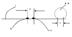
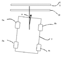
図11は、有料道路で通常用いられている軸数検知器に設けられた軸数センサの設置例であり、図において、8aは車両2の前輪(左)、8bは車両2の前輪(右)、9bは車両2の後輪(右)、10は第1の軸数センサ、20は第2の軸数センサであり、第1の軸数センサ10と第2の軸数センサ20とは、同一の構造と機能とを備えている。このような構成において、前輪(左)8aと前輪(右)8bとは車軸(図示せず)で結合され、前輪の車軸を構成する。また、後輪側も後輪(左)9a(図示せず)と後輪(右)9bとで後輪の車軸を構成する。第1の軸数センサ10と第2の軸数センサ20は、道路1の進行方向に対して直角に、かつ所定の間隔で埋設設置される。車両2の前進に伴い、第1の軸数センサ10、第2の軸数センサ20を順次前輪と後輪が踏み、移動する。
【0006】
図12は、軸数センサと車輪のタイヤとの関係を示す図であり、車両進行方向に対して側方から見た図である。図12において、5はタイヤであり、車両が進行するに伴い、第1の軸数センサ10、第2の軸数センサ20を通過する状況を示す。
図13は、第1の軸数センサ10、および第2の軸数センサ20の断面構造図であり、11は第1の接点、12は第2の接点、13は第1の接点の出力、14は第2の接点の出力、15は軸数センサの外皮であり、第1の接点11および第2の接点12を覆い浸水防止などを実現するものである。ここで図示したのは軸数センサの一例であり、タイヤ5が軸数センサを踏むことにより、オン(第1の接点11と第2の接点12とが接触)、タイヤ5が軸数センサを踏まない場合、オフ(第1の接点11と第2の接点12とが非接触)となる。なお、同等の機能を圧電効果により実現することもある。また、軸数センサの感知領域のどの部分をタイヤが踏んでも1つの信号として取り出すような構造となっている。図13において第1の接点11と第2の接点12は、車両のタイヤによって踏まれていない時は、互いに接触していない。図14は、タイヤ5によって矢印の方向に力が加わり、第1の接点11と第2の接点12とが接触した状態を示す。図15は、軸数センサの出力波形を示しており、軸数センサにタイヤが乗っていない状態ではオフ、タイヤが軸数センサに乗った状態ではオンとなる。即ち、タイヤの移動に伴って軸数センサからは「オフ」→「オン」→「オフ」と状態が変化する。
【0007】
図16は、従来の軸数検知器の構成を示す。図16において、21は第1の軸数センサ10の出力、22は第2の軸数センサ20の出力、23は、第1の軸数センサ10の出力21をセットとし、第2の軸数センサ20の出力22をリセットとするフリップフロップ、24はフリップフロップ23の出力、25はフリップフロップ出力24のパルス数を計測する計数回路である。なお、第1の軸数センサ10の出力21および第2の軸数センサ20の出力22は、実際には図13で示したようにそれぞれ2つの接点で構成されるが、簡単のため1つの出力で示した。
このような構成において、車両2が道路を進行するに伴い、第1の軸数センサ10、第2の軸数センサ20が車両2のタイヤによって順次踏まれ、第1の軸数センサの出力21、第2の軸数センサの出力22が、順次「オフ」→「オン」→「オフ」に変化する。フリップフロップ23は、第1の軸数センサ10の出力21の立ち上がり(「オフ」→「オン」)によってセットされ、第2の軸数センサ20の出力22の立ち上がり(「オフ」→「オン」)によってリセットされるようにしてあり、1つの車軸が前進することによってフリップフロップ出力24にパルスが1つ発生する。前輪と後輪からなる車両が通過するとフリップフロップ出力24にパルスが2つ発生する。計数回路25はこのパルス数を計数するので通過した車両が2軸であることが検知できる。なお、簡単な回路構成とする場合には、単に第1の軸数センサ10の出力21、第2の軸数センサ20の出力22を計数することもある。
【0008】
【発明が解決しようとする課題】
図16で示した従来の軸数検知器の構成では、車両が第1の軸数センサ10、第2の軸数センサ20に対して直角に進入してきた場合は、正常に軸数を計数できるが、斜めに進入してきた場合、過剰計数することがある。図17は、車両の斜め進入についての説明図であり、道路上方から道路面を俯瞰した図であり、図において図中の2、8a、8b、9a、10、20は図10の同一符号部と同一あるいは同等のものである。図では、車両2が図の矢印方向、即ち直進方向に対して角度θで斜め進入した場合を示している。
この時、角度θと第1の軸数センサ10の出力21との関係を図18、図19及び図20に示し、いずれも左右に1つずつのタイヤを持つ車軸1本についての状況を示す。ここで、図18は、進入角度θがほぼゼロの場合、図19はある程度進入角度θが小さい場合、図20は進入角度θが大きい場合を示している。図18に示すように、進入角度θが小さい場合は、前輪(左)8aと前輪(右)8bはほぼ同時に第1の軸数センサ10に進入する。しかし、進入角度θが大きくなるに従い、前輪(右)8bは前輪(左)8aに遅れて第1の軸数センサ10に到達する。
この結果、図19から図20に示すような出力が発生し、特に図20では、第1の軸数センサ10から2個のパルスが発生して、本来、前輪のみでは1軸であるにも拘わらず、2軸として誤った計測を行う。また、軸数センサとして図13に示すように軸数センサのどの部分をタイヤが踏んでも1つの信号として取り出すようなものではなく、道路幅員方向に例えば30cm毎にその踏んだ位置が検出できるような構成のものもあるが、この場合は、軸数センサを多数の検知部分で構成する必要があり、センサそのものが高価になると共に、その信号処理も複雑化してしまう。
【0009】
図21は、従来の軸数検知器の構成における出力波形図であり、進入角度θが大きい場合、即ち図20で示した進入状態の場合での第1の軸数センサ10と第2の軸数センサ20の出力を示す波形図である。図において前述のように、第1の軸数センサ10の出力11の立ち上がりでセットし、第2の軸数センサ20の出力12の立ち上がりでリセットするような場合では、図示のように前輪のみで2個のパルスを発生し、この場合後輪の計測と併せて、車両2の軸数が4であるかの如く誤った計測をしてしまう。
以上述べたとおり、従来の軸数検知器の構成では、車両の斜め進入に対して軸数を過剰計測する場合があった。このため、ETCにおいて、軸数検知器の出力する軸数に基づいて車種判別を行う場合や、車載器4に記憶され通信によって得られた軸数データと軸数検知器の出力する軸数との比較判別を行う場合に、正確な判別を行うことができなくなり、車両の情報の入手や料金収受を正しく行えないという問題があった。
【0010】
この発明は、上記の課題を解決するためになされたものであり、正確に軸数を計測する軸数検知器を提供するものである。
【0011】
【課題を解決するための手段】
第1の発明による軸数検知装置は、道路の路幅方向に設置され、車両のタイヤに踏まれてタイヤを検知する軸数センサを有し、上記軸数センサによるタイヤの検知に応じて車両の軸数を計測する軸数検知装置において、道路の進路方向における車両のタイヤの接地長さ以下の間隔で、上記軸数センサを2個並置し、上記2つの軸数センサのいずれもが上記車両のタイヤを検知した時にオンとなる第1の処理回路と、上記2つの軸数センサのいずれもが上記車両のタイヤを検知していない時にオンとなる第2の処理回路と、上記第1の処理回路の出力オンに基づきセットされ、上記第2の処理回路の出力オンに基づきリセットされるフリップフロップ回路と、当該フリップフロップ回路の出力に基づいて上記車両の軸数を計数する計数手段とを備えたものである。
【0012】
第2の発明による軸数検知装置は、道路の路幅方向に設置され、車両のタイヤに踏まれてタイヤを検知する軸数センサを有し、上記軸数センサによるタイヤの検知に応じて車両の軸数を計測する軸数検知装置において、道路の進路方向における車両のタイヤの接地長さ以下の間隔で、上記軸数センサを2個並置し、上記2つの軸数センサが両方ともオンとなった時に計数用のパルス信号をオンの状態とするとともに、上記2つの軸数センサが両方ともオフとなった時に当該パルス信号をオフの状態とする処理回路と、上記処理回路から出力されるパルス信号のパルス数に基づいて上記車両の軸数を計数する計数手段とを備えたものである。
【0013】
第3の発明による軸数検知装置は、上記第1、第2の発明のいずれかの発明において、上記軸数センサは、車両に許容される進入角度範囲内で車両が斜め進入する際に、同一車軸の一方の車輪が一方の軸数センサを踏み始めてから両車輪が軸数センサを両方とも通過するまでの間、2つの軸数センサのいずれか一方が踏まれているように、当該2つの軸数センサの間隔を設定したものである。
【0014】
第4の発明による軸数検知装置は、上記第1、第2の発明のいずれかの発明において、上記2つの軸数センサの間隔を、概ね70〜80mmとしたものである。
【0015】
第5の発明による軸数検知装置は、上記第1、第2の発明のいずれかの発明において、上記軸数検知装置は、路幅方向の両側にアイランドが設置された道路に配置したものである。
【0016】
第6の発明による軸数検知装置は、上記第1〜第5の発明のいずれかの発明において、車両の進入を検知する車両検知器と、上記車両検知器の検知に応じて上記2つの軸数センサが上記タイヤを検知する順序を計測し、当該計測された順序に基づいて上記車両の進行方向を識別する方向弁別手段とを備えたものである。
【0017】
第7の発明による車種判別装置は、上記第1〜第6の発明のいずれかに記載の軸数検知装置を備え、上記軸数検知装置で計測された軸数に基づいて車種を判別するものである。
【0018】
第8の発明による料金収受システムは、車両に搭載された車載器と路上に設けられた路側機との間で通信を行うことにより、通行料金を収受する料金収受システムにおいて、上記第1から第6の発明のいずれかに記載の軸数検知装置と、上記軸数検知装置で計測された軸数の情報と上記車載器に記憶され当該車載器から送信された軸数の情報とを比較する比較手段とを備え、この比較結果に基づいて通行料金を収受するものである。
【0019】
第9の発明による軸数検知装置は、車両に搭載された車載器と路上に設けられた路側機との間で通信を行うことにより、通行料金を収受する料金収受システムにおいて、上記第1から第6の発明のいずれかに記載の軸数検知装置と、上記軸数検知装置で計測された軸数の情報と上記車載器に記憶され当該車載器から送信された軸数の情報とを比較する比較手段とを備え、この比較結果に基づいて通行料金を収受するものである。
【0020】
【発明の実施の形態】
実施の形態1.
図1は、この発明の実施の形態1を示す軸数検知器の構成図、図2はこの実施の形態1における、タイヤと軸数センサの設置関係を示す図、図3はこの実施の形態1における波形図である。
図1において、26は、第1の軸数センサ10の出力21と第2の軸数センサ20の出力22とを入力とし、いずれかがオンのとき、即ち第1の軸数センサ10と第2の軸数センサ20のいずれかがタイヤによって踏まれている場合にオア回路26の出力27をオンにし、第1の軸数センサ10と第2の軸数センサ20のいずれもがタイヤによって踏まれていない状態の時にオフする回路であり、計数回路25は、オア回路26の出力27のオンの数を数える計数回路、28は計数回路27の計数出力である。図2において、Dは第1の軸数センサ10と第2の軸数センサ20との道路進行方向での間隔、Lはタイヤ5の道路進行方向における接地長さであり、D<Lの条件で設置する。自動車に使われるタイヤの諸元は規定されており、例えば軽自動車では145R12が、普通乗用車では145R13などが使用される。最もタイヤ径の小さい軽自動車の145R12の場合、タイヤ径は約480mmあり、その接地部分の長さLは100mmから120mm程度である。従って軸数センサの接地間隔Dは100mm以下とすることになる。
【0021】
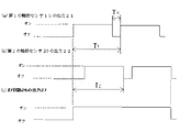
図3は、車両が斜め進入した場合の各部の波形を示しており、進入角度θは図2に示した状態に相当している。図3に基づいて説明する。車両2が第1の軸数センサ10、第2の軸数センサ20に対して斜め進入した場合は、第1の軸数センサ10の出力21は、図示のように前輪(左)と前輪(右)が時間をあけて軸数センサを踏むため、図示のように、一旦波形が落ち込む、つまり波形割れを持つ波形となる。また、第2の軸数センサ20の出力22も同様となる。この時、オア回路出力27は、第1の軸数センサ10の出力21と第2の軸数センサ20の出力22のいずれかがオンの時にオンになり図示のような出力となる。この結果、前輪の移動に伴って第1の軸数センサ10の出力21と第2の軸数センサ20の出力22が、それぞれ一旦オンになった後、両者の波形割れの部分が重なり会わない範囲の進入角度まで正常に軸数を計数することができる。Dを70mmとし、軽自動車を使った実験によると、図1の構成により、進入角度θが9度まで正しく軸数を計測できている。料金所は、一般的に道路幅3mで、道路両側にはアイランドと呼ばれる構造が施されており、車両が斜め進入し難い構造であって、上記の進入角度約9度は実用上問題のない値である。なお、車両がある程度以上の進入角度θ(例えば5°以上)で斜めに進入する際、図3に示すように前輪(左)と前輪(右)におけるそれぞれのタイヤの接地面が、車軸の傾きに応じて間隔Kを空けて第1の軸数センサ10をそれぞれ順に踏むことがある(第2の軸数センサ20についても同様)。このとき、Dの大きさを小さくし過ぎると、間隔Kに対応したある時間Tk内において、第1、第2の軸数センサ10、20の出力21と出力22が両方ともオフになる区間を生じてしまう。したがって、車両の所定の進入角度θ内(例えば9°以下)において、図3に示すように時間T2(前輪(左もしくは右)が第1の軸数センサ10を踏み始めてから前輪(右もしくは左)が第2の軸数センサ20を通過するまでの時間)が、時間T1(前輪(左もしくは右)が第1の軸数センサ10を踏み始めてから前輪(右もしくは左)が第1の軸数センサ10を踏み始めるまでの時間)よりも大きくなるように、Dの大きさを適宜設定しておくことが望ましい(例えば、50mm≦D≦100mmとする。より好ましくはDを概ね70〜80mmとすると良い。)。
以上のように軸数検知器を構成することにより、特定の車線幅内を通過する車両が軸数センサに対して斜めに進入した場合であっても、軸数を正確に計測できる。また、ETCのように軸数情報が重要な役割を果たすシステムに適用した場合、実用に供する軸数検知器を提供することができる。例えば、軸数検知器で計測された軸数に基づいて車種判別を行う際に、軸数を誤りなく計測できるため、正確な車種判別を行うことができる。また、車載器4との通信で得られた軸数データ(あるいは車種情報)と軸数検知器で判別された軸数(あるいは車種判別装置からの車種情報)とを比較する軸数比較器においても、正確な判別が可能となる。
【0022】
実施形態2.
図4は、この発明の実施の形態2を示す軸数検知器の構成図である。図4において29は方向弁別回路、30は方向弁別回路29の出力である前進検知信号、30は方向弁別回路29の出力である前進検知信号、32は第1のゲート回路、33は第2のゲート回路、40は投光器、41は受光器、42は車両検知出力である。なお、タイヤと軸数センサの設置関係は、図2が適用される。また、投光器40と、受光器41は、車両が通過する道路の両側に、かつ第1の軸数センサ10の近傍の上流側にそれぞれ設置され、車両が投光器40と受光器41の間を通過する際、車両の前端部周辺もしくは後端部周辺が投光器40からの光を遮ったときに車両検知信号42を出力する。図4において、方向弁別回路29は、第1の軸数センサ10の出力21と第2の軸数センサ20の出力22とを入力とし、第1の軸数センサ10と第2の軸数センサ20のいずれが時間的に先行してタイヤによって踏まれたかを弁別するものであり、具体的にはフリップフロップなどで実現され、第1の軸数センサ10が時間的に第2の軸数センサ20に先行して踏まれた場合には前進検知信号30を、逆に第2の軸数センサ20が時間的に第1の軸数センサ10に先行して踏まれた場合には後退検知信号31を出すようになっている。
【0023】
また、方向弁別回路29は、車両前端部周辺もしくは後端部周辺が投光器40と受光器41の間をよぎり、車両検知信号42が出力された場合に動作を開始するようにしてあり、車両の進行方向の弁別を車両に対してのみ動作するようにしている。第1のゲート回路32は、計数出力28が前進検知信号30によってゲートが掛けられているため、車両が前進した場合にその軸数計数結果が出力される。また、第2のゲート回路33は、計数出力28が後退検知信号31によってゲートが掛けられているため、車両が後退した場合にその軸数計数結果が出力される。これによって前進の場合と後進の場合を区別して軸数を計測できる。このように、実施の形態1では車両の進行方向が判別できないのに比べ、実施の形態2では車両の進行方向と、その際の軸数を計数できる。
【0024】
実施形態3.
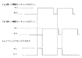
図5は、この発明の実施の形態3を示す軸数検知器の構成図である。図5において、34は第1の処理回路、35は第2の処理回路、36は第1の処理回路34の出力、37は第2の処理回路35の出力、28は計数回路25の出力である。なお、タイヤと軸数センサの設置関係は、図2と同様である。図において、10、20、21、22、23、24、25は、図15の同一符号部と同等の機能をもつ。このような構成において、第1の処理回路34は、第1の軸数センサ出力21と第2の軸数センサ出力22とがいずれもがオンのとき、即ち、第1の軸数センサ10と第2の軸数センサ20のいずれもがタイヤによって踏まれた状態の場合、第1の処理回路出力36をオンにするようになっている。また、第2の処理回路35は、第1の軸数センサ出力21と第2の軸数センサ出力22とがいずれもがオフのとき、即ち、第1の軸数センサ10と第2の軸数センサ20のいずれもがタイヤによって踏まれない状態の場合、第2の処理回路出力37をオンにするようになっている。また、フリップフロップ23は、第1の処理回路出力36の立ち上がり(オフ→オン)でセットされ、第2の処理回路出力37の立ち上がり(オフ→オン)でリセットされるようになっている。計数回路25はフリップフロップ23の出力38のパルス数を計数し、計数回路出力28を出す。
【0025】
図6は、車両が斜め進入した場合の各部の波形を示しており、進入角度θは図2に示した状態に相当している。図6に基づいて説明する。車両2が第1の軸数センサ10、第2の軸数センサ20に対して斜め進入した場合は、第1の軸数センサ10の出力21は、前輪(左)と前輪(右)が時間をあけて軸数センサを踏むため、図示のように、一旦波形が落ち込む、つまり波形割れを持つ波形となる。また、第2の軸数センサ20の出力22も同様となる。この時、第1の処理回路34の出力36は、第1の軸数センサ10の出力21と第2のセンサ20の出力22のいずれもがオンの時にオンになり図示のような出力となる。また、第2の処理回路35の出力37は、第1の軸数センサ10の出力21と第2のセンサ20の出力22のいずれもがオフの時ににオンになり、図示のような出力となる。一方、フリップフロップ23は、第1の処理回路34の出力36の立ち上がりでセットされ、また第2の処理回路35の出力37の立ち上がりでリセットされ、図6(e)に示すように動作する。この結果、前輪の移動に伴って第1の軸数センサ10の出力21と第2の軸数センサ20の出力22が、それぞれ一旦オンになった後、両者の波形割れの部分が重なり会わない範囲の進入角度まで正常に軸数を計数することができる。
【0026】
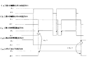
なお、実施の形態1との比較を図7と図8に示す。いずれも軸数センサの出力にチャタリングのある場合の比較であり、図7は実施の形態1の場合の波形図、図8は実施の形態3の場合の波形図である。図7に示すように軸数センサのチャタリングは、即オア回路の出力に表われ、軸数の過剰計測が発生する。一方、図8ではフリップフロップ回路23の効果によって軸数の過剰計測は防止される。
【0027】
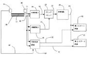
実施形態4.
図9は、この発明の実施の形態4を示す軸数検知器の構成図である。図9は、実施の形態3の構成に加えて方向弁別機能を付加している。つまり、実施の形態3の構成に、方向弁別回路29、投光器40、受光器41、第1のゲート回路22および第2のゲート回路33を付加することによって、車両が前進、即ち第1の軸数センサ10→第2の軸数センサ20の方向に移動した場合の軸数、逆に車両が後退即ち即ち第2の軸数センサ20→第1の軸数センサ10の方向に移動した場合の軸数を検知できるようにしている。
【0028】
なお、実施の形態1から4において、第1の軸数センサ10と第2の軸数センサ20の2つの軸数センサを用いた構成について説明してきたが、上記構成に加えて、例えば軸数センサの摩耗などによる故障への対応のため、予備系の軸数センサを予め設置しておくことも可能であることは言うまでもない。
【0029】
【発明の効果】
この発明によれば、軸数センサに対して斜めに進入した場合にも一定の進入角度内では軸数を正確に計測できると共に、軸数センサの近傍で停止あるいは少し移動した場合に生ずるセンサのチャタリングを克服できる。
【図面の簡単な説明】
【図1】 この発明の実施の形態1を示す軸数検知器の構成図である。
【図2】 タイヤと軸数センサの設置関係を示す図である。
【図3】 この発明の実施の形態1における波形図である。
【図4】 この発明の実施の形態2を示す軸数検知器の構成図である。
【図5】 この発明の実施の形態3を示す軸数検知器の構成図である。
【図6】 この発明の実施の形態3における波形図である。
【図7】 この発明の実施の形態1でチャタリングがある場合の波形図である。
【図8】 この発明の実施の形態3でチャタリングがある場合の波形図である。
【図9】 この発明の実施の形態4を示す軸数検知器の構成図である。
【図10】 ETCの基本構成を示す図である。
【図11】 軸数センサの設置例を示す図である。
【図12】 軸数センサとタイヤとの関係を示す図である。
【図13】 軸数センサの断面構造図を示す図である。
【図14】 軸数センサの動作図を示す図である。
【図15】 軸数センサの出力波形を示す図である。
【図16】 車両の斜め進入を示す図である。
【図17】 進入角度がほぼ0の場合の軸数センサの出力を示す図である。
【図18】 進入角度がある程度小さい場合の軸数センサの出力を示す図である。
【図19】 進入角度がある程度大きい場合の軸数センサの出力を示す図である。
【図20】 従来の軸数検知器の構成における出力波形図を示す図である。
【図21】 従来の軸数検知器の構成を示す図である。
【符号の説明】
1 道路
2 車両
3 路側アンテナ
4 車載器
5 タイヤ
6 料金所情報
7 車載器情報
8 前輪
8a 前輪(左)
8b 前輪(右)
9 後輪
9a 後輪(左)
9b 後輪(右)
10 第2の軸数センサ
11 第1の接点
12 第2の接点
13 第1の接点の出力
14 第2の接点の出力
15 外皮
20 第2の軸数センサ
21 第1の軸数センサの出力
22 第2の軸数センサの出力
23 フリップフロップ
24 フリップフロップ出力
25 計数回路
26 オア回路
27 オア回路の出力
28 計数出力
29 方向弁別回路
30 前進検知信号
31 後退検知信号
32 第1のゲート回路
33 第2のゲート回路
40 投光器
41 受光器
42 車両検知信号[0001]
BACKGROUND OF THE INVENTION
In road traffic, the present invention relates to a shaft number detection device that detects the number of axes of a vehicle using a sensor embedded in the road, and vehicle type determination using the number of shaft detection device, and a vehicle mounted with an in-vehicle device. It is related to the technology that collects the charges by performing communication.
[0002]
[Prior art]
In recent years, development momentum related to the advancement of road traffic systems (Intelligent Transport System, hereinafter referred to as ITS) is increasing. In Japan as well, in February 1995, the government's “Basic Policy for the Promotion of an Advanced Information and Communication Society” decided to promote ITS. Implementation guidelines "have been launched, in which 11 promotion measures and 9 development areas are shown. Here, the nine development areas are advanced navigation, automatic toll collection system, safe driving support, traffic management optimization, road management efficiency, public transport support, commercial vehicle efficiency, pedestrians Etc. and emergency vehicle operation support).
[0003]
In addition, as described in “First Appearance of Automatic Charge Collection in Metropolitan Area High Speed” in the Nihon Keizai Shimbun (1998-8-28 evening), communication is performed between the vehicle-mounted device mounted on the vehicle and the roadside antenna installed on the roadside. Development of a non-stop automatic toll collection system (Electronic Toll Collection, hereinafter referred to as ETC) that automatically collects tolls is also promoted. Here, the basic configuration of ETC is shown in FIG. In FIG. 10, 1 is a road, 2 is a vehicle, 3 is a roadside antenna attached to a roof of a toll booth (not shown), and connected to a roadside machine (not shown), 4 is a vehicle-mounted device, for example Thus, the
The vehicle-mounted
[0004]
On the other hand, on toll roads, the toll collected depends on the type of vehicle, and the factors that determine the type of vehicle are the vehicle length, the vehicle width, the number of axes, the vehicle height, the presence or absence of towing, and the like. For example, on city expressways, the flat fee system is mainly used, and the charges differ between ordinary cars and large cars. In addition, the intercity expressway mainly uses an entrance ticketing / exit collection method, and a toll vehicle system divided into light cars, ordinary cars, medium-sized cars, large-sized cars, and extra-large cars is applied. In the case of a towed vehicle, when a normal vehicle is towed, a fee of a medium-sized vehicle that is one step higher is applied, such as a fee that is one step higher.
In the ETC, the number of axes of a passing vehicle entering the communication area with the roadside antenna is measured by an axis number detector installed on the road, and this number of axes is preset by a vehicle type discriminating device (not shown). The vehicle type of the passing vehicle is determined on the basis of the number of axes and the information defining the correspondence relationship with the vehicle type, and the vehicle type determination information is output to the roadside machine. Stored as vehicle history data. Further, in a shaft number comparator (not shown), the shaft number data (or vehicle type information) in the toll vehicle type information obtained by communication between the
[0005]
FIG. 11 is an installation example of an axis number sensor provided in an axis number detector normally used on a toll road. In the figure, 8a is a front wheel (left) of the
[0006]
FIG. 12 is a diagram illustrating a relationship between the number-of-axis sensors and the wheel tires, as viewed from the side with respect to the vehicle traveling direction. In FIG. 12, reference numeral 5 denotes a tire, and shows a situation where the vehicle passes through the first
FIG. 13 is a cross-sectional structure diagram of the first
[0007]
FIG. 16 shows the configuration of a conventional axis number detector. In FIG. 16, 21 is the output of the first
In such a configuration, as the
[0008]
[Problems to be solved by the invention]
In the configuration of the conventional axis number detector shown in FIG. 16, when the vehicle enters at a right angle to the first
At this time, the relationship between the angle θ and the
As a result, an output as shown in FIG. 19 to FIG. 20 is generated. In particular, in FIG. 20, two pulses are generated from the first
[0009]
FIG. 21 is an output waveform diagram in the configuration of the conventional axis number detector, in which the first
As described above, in the configuration of the conventional axis number detector, the number of axes may be excessively measured with respect to the oblique approach of the vehicle. Therefore, in ETC, when the vehicle type is determined based on the number of axes output from the axis number detector, or the axis number data stored in the vehicle-mounted device 4 and obtained by communication, and the number of axes output from the axis number detector When the comparison determination is performed, accurate determination cannot be performed, and there is a problem that vehicle information cannot be obtained and toll collection cannot be performed correctly.
[0010]
The present invention has been made to solve the above problems.RightAn axis number detector that accurately measures the number of axes is provided.
[0011]
[Means for Solving the Problems]
According to a first aspect of the present invention, there is provided an axis number detection device having an axis number sensor that is installed in a road width direction of a road and detects a tire by being stepped on a tire of the vehicle, and the vehicle according to tire detection by the axis number sensor. In the axis number detecting device for measuring the number of axes of the two, the two axis number sensors are juxtaposed at intervals equal to or less than the contact length of the tire of the vehicle in the road direction of the road, and both of the two axis number sensors are A first processing circuit that is turned on when a vehicle tire is detected; a second processing circuit that is turned on when neither of the two shaft number sensors detects the vehicle tire; A flip-flop circuit that is set when the output of the processing circuit is turned on and reset when the output of the second processing circuit is turned on, and a counting means that counts the number of axes of the vehicle based on the output of the flip-flop circuit The Those were example.
[0012]
According to a second aspect of the present invention, there is provided an axis number detection device having an axis number sensor that is installed in a road width direction of a road and detects a tire by being stepped on a tire of the vehicle, and the vehicle according to the tire detection by the axis number sensor. In the axis number detecting device for measuring the number of axes of the two, the two axis number sensors are juxtaposed at intervals equal to or shorter than the ground contact length of the vehicle tire in the direction of the road, and both of the two axis number sensors are turned on. A counting pulse signal which is turned on when the two axis number sensors are turned off, and a processing circuit which turns off the pulse signal when both of the two axis number sensors are turned off, and is output from the processing circuit. And a counting means for counting the number of axes of the vehicle based on the number of pulses of the pulse signal.
[0013]
According to a third aspect of the present invention, there is provided the number-of-axis detection device according to any one of the first and second aspects, wherein the number-of-axis sensor is configured such that when the vehicle enters obliquely within an approach angle range allowed for the vehicle, From the time when one wheel of the same axle starts to step on one of the shaft number sensors to the time when both wheels pass both of the shaft number sensors, the two axle number sensors are stepped on. The interval between two axis number sensors is set.
[0014]
According to a fourth aspect of the present invention, there is provided the number-of-axis detecting device according to any one of the first and second aspects, wherein the distance between the two number-of-axis sensors is approximately 70 to 80 mm.
[0015]
According to a fifth aspect of the present invention, there is provided the number-of-axis detection device according to any one of the first and second aspects, wherein the number-of-axis detection device is disposed on a road having islands installed on both sides in the road width direction. is there.
[0016]
The number-of-axis detection device according to a sixth aspect of the present invention is the vehicle detector according to any one of the first to fifth aspects, wherein the two detectors detect the approach of the vehicle and the two shafts according to the detection of the vehicle detector The number sensor measures the order in which the tires are detected, and includes direction discriminating means for identifying the traveling direction of the vehicle based on the measured order.
[0017]
A vehicle type discriminating device according to a seventh invention comprises the axle number detection device according to any one of the first to sixth inventions, and discriminates a vehicle type based on the number of axes measured by the axle number detection device. It is.
[0018]
A toll collection system according to an eighth aspect of the present invention is a toll collection system that collects a toll by performing communication between an on-vehicle device mounted on a vehicle and a roadside device provided on the road. The number-of-axis detection device according to any one of the sixth invention, the number-of-axis information measured by the number-of-axis detection device, and the number-of-axis information stored in the on-vehicle device and transmitted from the on-vehicle device are compared. Comparing means is provided, and the toll is collected based on the comparison result.
[0019]
According to a ninth aspect of the present invention, there is provided a toll collection system for collecting a toll by performing communication between an onboard device mounted on a vehicle and a roadside device provided on the road. The number-of-axis detection device according to any one of the sixth invention, the number-of-axis information measured by the number-of-axis detection device, and the number-of-axis information stored in the on-vehicle device and transmitted from the on-vehicle device And a toll is collected based on the comparison result.
[0020]
DETAILED DESCRIPTION OF THE INVENTION
FIG. 1 is a configuration diagram of an axis number
In FIG. 1,
[0021]
FIG. 3 shows a waveform of each part when the vehicle enters obliquely, and the approach angle θ corresponds to the state shown in FIG. This will be described with reference to FIG. When the
By configuring the axis number detector as described above, the number of axes can be accurately measured even when a vehicle passing through a specific lane width enters obliquely with respect to the axis number sensor. Moreover, when applied to a system in which axis number information plays an important role, such as ETC, an axis number detector for practical use can be provided. For example, when determining the vehicle type based on the number of axes measured by the axis number detector, the number of axes can be measured without error, so that accurate vehicle type determination can be performed. Further, in an axis number comparator for comparing the axis number data (or vehicle type information) obtained by communication with the vehicle-mounted device 4 and the number of axes determined by the axis number detector (or the vehicle type information from the vehicle type identification device). However, accurate discrimination is possible.
[0022]
FIG. 4 is a configuration diagram of an axis number detector showing the second embodiment of the present invention. In FIG. 4, 29 is a direction discrimination circuit, 30 is a forward detection signal that is an output of the
[0023]
The direction discriminating circuit 29 is arranged around the front end of the vehicle or around the rear end.Side isThe operation is started when the
[0024]
FIG. 5 is a configuration diagram of an axis number detector showing the third embodiment of the present invention. In FIG. 5, 34 is a first processing circuit, 35 is a second processing circuit, 36 is an output of the
[0025]
FIG. 6 shows a waveform of each part when the vehicle enters obliquely, and the approach angle θ corresponds to the state shown in FIG. This will be described with reference to FIG. When the
[0026]
A comparison with the first embodiment is shown in FIGS. Both are comparisons in the case where chattering is present in the output of the axis number sensor, FIG. 7 is a waveform diagram in the case of the first embodiment, and FIG. 8 is a waveform diagram in the case of the third embodiment. As shown in FIG. 7, the chattering of the axis number sensor immediately appears in the output of the OR circuit, resulting in excessive measurement of the number of axes. On the other hand, in FIG. 8, the excessive measurement of the number of axes is prevented by the effect of the flip-
[0027]
Embodiment 4 FIG.
FIG. 9 is a configuration diagram of an axis number detector showing the fourth embodiment of the present invention. FIG. 9 adds a direction discrimination function in addition to the configuration of the third embodiment. That is, by adding the direction discriminating circuit 29, the
[0028]
In the first to fourth embodiments, the configuration using the two axis number sensors, the first
[0029]
【The invention's effect】
According to the present invention, the number of axes can be accurately measured within a certain approach angle even when entering the axis number sensor at an angle, and the sensor generated when stopped or moved slightly in the vicinity of the axis number sensor. Overcoming chattering.
[Brief description of the drawings]
FIG. 1 is a configuration diagram of an axis number detector showing a first embodiment of the invention.
FIG. 2 is a diagram showing an installation relationship between a tire and an axis number sensor.
FIG. 3 is a waveform diagram according to the first embodiment of the present invention.
FIG. 4 is a configuration diagram of an axis number detector showing a second embodiment of the present invention.
FIG. 5 is a configuration diagram of an axis number
FIG. 6 is a waveform diagram in the third embodiment of the present invention.
FIG. 7 is a waveform diagram in the case where there is chattering in the first embodiment of the present invention.
FIG. 8 is a waveform diagram when there is chattering in the third embodiment of the present invention.
FIG. 9 is a configuration diagram of an axis number detector showing Embodiment 4 of the present invention.
FIG. 10 is a diagram showing a basic configuration of ETC.
FIG. 11 is a diagram illustrating an installation example of an axis number sensor.
FIG. 12 is a diagram illustrating a relationship between an axis number sensor and a tire.
FIG. 13 is a diagram showing a cross-sectional structure diagram of an axis number sensor.
FIG. 14 is a diagram showing an operation diagram of an axis number sensor.
FIG. 15 is a diagram showing an output waveform of an axis number sensor.
FIG. 16 is a diagram showing an oblique approach of a vehicle.
FIG. 17 is a diagram showing the output of an axis number sensor when the approach angle is almost zero.
FIG. 18 is a diagram showing the output of an axis number sensor when the approach angle is small to some extent.
FIG. 19 is a diagram showing the output of an axis number sensor when the approach angle is somewhat large.
FIG. 20 is a diagram showing an output waveform diagram in the configuration of a conventional axis number detector.
FIG. 21 is a diagram showing a configuration of a conventional axis number detector.
[Explanation of symbols]
1 road
2 Vehicle
3 Roadside antenna
4 Onboard equipment
5 tires
6 Tollgate information
7 OBE information
8 Front wheels
8a Front wheel (left)
8b Front wheel (right)
9 Rear wheel
9a Rear wheel (left)
9b Rear wheel (right)
10 Second axis number sensor
11 First contact
12 Second contact
13 Output of first contact
14 Output of second contact
15 skin
20 Second axis number sensor
21 Output of first axis number sensor
22 Output of second axis number sensor
23 flip-flops
24 flip-flop output
25 Counting circuit
26 OR circuit
27 OR circuit output
28 Counting output
29-way discrimination circuit
30 Forward detection signal
31 Reverse detection signal
32 First gate circuit
33 Second gate circuit
40 Floodlight
41 Receiver
42 Vehicle detection signal
Claims (8)
道路の進路方向における車両のタイヤの接地長さ以下の間隔で、上記軸数センサを2個並置し、
上記2つの軸数センサのいずれもが上記車両のタイヤを検知した時にオンとなる第1の処理回路と、上記2つの軸数センサのいずれもが上記車両のタイヤを検知していない時にオンとなる第2の処理回路と、上記第1の処理回路の出力オンに基づきセットされ、上記第2の処理回路の出力オンに基づきリセットされるフリップフロップ回路と、当該フリップフロップ回路の出力に基づいて上記車両の軸数を計数する計数手段とを備えたことを特徴とする軸数検知装置。In an axis number detection device that is installed in the width direction of a road, has an axis number sensor that detects a tire by being stepped on a tire of the vehicle, and measures the number of axes of the vehicle according to the detection of the tire by the axis number sensor ,
Two axis number sensors are juxtaposed at intervals equal to or less than the ground contact length of the vehicle tire in the direction of the road,
On and when the first processing circuit neither of the two axes speed sensor is turned on when detecting a tire of the vehicle, neither of the two axes speed sensor does not detect the tire of the vehicle A second processing circuit, a flip-flop circuit that is set when the output of the first processing circuit is turned on and reset when the output of the second processing circuit is turned on, and an output of the flip-flop circuit A number-of-axis detection device comprising: counting means for counting the number of axes of the vehicle.
道路の進路方向における車両のタイヤの接地長さ以下の間隔で、上記軸数センサを2個並置し、
上記2つの軸数センサが両方ともオンとなった時に計数用のパルス信号をオンの状態とするとともに、上記2つの軸数センサが両方ともオフとなった時に当該パルス信号をオフの状態とする処理回路と、
上記処理回路から出力されるパルス信号のパルス数に基づいて上記車両の軸数を計数する計数手段とを備えたことを特徴とする軸数検知装置。In an axis number detection device that is installed in the width direction of a road, has an axis number sensor that detects a tire by being stepped on a tire of the vehicle, and measures the number of axes of the vehicle according to the detection of the tire by the axis number sensor ,
Two axis number sensors are juxtaposed at intervals equal to or less than the ground contact length of the vehicle tire in the direction of the road,
With a pulse signal on state for counting at the two axes speed sensor is turned on both, and turned off the pulse signal at the two-axis rate sensor is turned off both A processing circuit;
An axis number detecting device comprising: a counting means for counting the number of axes of the vehicle based on the number of pulses of the pulse signal output from the processing circuit.
車両に許容される進入角度範囲内で車両が斜め進入する際に、同一車軸の一方の車輪が一方の軸数センサを踏み始めてから両車輪が軸数センサを両方とも通過するまでの間、2つの軸数センサのいずれか一方が踏まれているように、当該2つの軸数センサの間隔を設定したことを特徴とする請求項1、2のいずれかに記載の軸数検知装置。The number of axes sensor is
When a vehicle enters obliquely within an approach angle range that is allowed for the vehicle, a period from when one wheel of the same axle starts to step on one of the shaft number sensors until both wheels pass both of the shaft number sensors is 2 The number-of-axis detection device according to claim 1 , wherein an interval between the two number-of-axis sensors is set so that one of the two number-of-axis sensors is stepped on.
Priority Applications (1)
| Application Number | Priority Date | Filing Date | Title |
|---|---|---|---|
| JP2000167626A JP4089134B2 (en) | 2000-06-05 | 2000-06-05 | Axis number detection device, vehicle type identification device, and toll collection system |
Applications Claiming Priority (1)
| Application Number | Priority Date | Filing Date | Title |
|---|---|---|---|
| JP2000167626A JP4089134B2 (en) | 2000-06-05 | 2000-06-05 | Axis number detection device, vehicle type identification device, and toll collection system |
Publications (3)
| Publication Number | Publication Date |
|---|---|
| JP2001351131A JP2001351131A (en) | 2001-12-21 |
| JP2001351131A5 JP2001351131A5 (en) | 2005-09-08 |
| JP4089134B2 true JP4089134B2 (en) | 2008-05-28 |
Family
ID=18670754
Family Applications (1)
| Application Number | Title | Priority Date | Filing Date |
|---|---|---|---|
| JP2000167626A Expired - Lifetime JP4089134B2 (en) | 2000-06-05 | 2000-06-05 | Axis number detection device, vehicle type identification device, and toll collection system |
Country Status (1)
| Country | Link |
|---|---|
| JP (1) | JP4089134B2 (en) |
Cited By (1)
| Publication number | Priority date | Publication date | Assignee | Title |
|---|---|---|---|---|
| CN106205150A (en) * | 2016-07-20 | 2016-12-07 | 安徽建筑大学 | Internet of vehicles road condition monitoring system |
Families Citing this family (1)
| Publication number | Priority date | Publication date | Assignee | Title |
|---|---|---|---|---|
| JP6344770B2 (en) * | 2015-01-13 | 2018-06-20 | アルパイン株式会社 | Electronic device, billing display program, and billing display method |
Family Cites Families (10)
| Publication number | Priority date | Publication date | Assignee | Title |
|---|---|---|---|---|
| JPS5835313B2 (en) * | 1979-04-17 | 1983-08-02 | 富士電機株式会社 | Vehicle axle number measurement circuit |
| JPS56149699A (en) * | 1980-04-22 | 1981-11-19 | Mitsubishi Heavy Ind Ltd | Vehicle passage identifying device |
| JPS57117097A (en) * | 1981-01-13 | 1982-07-21 | Fuji Electric Co Ltd | Detection system of number of shafts for passing vehicles |
| JPS59165200A (en) * | 1983-03-10 | 1984-09-18 | 富士電機株式会社 | Vehicle type discriminator for three-wheel vehicle |
| JPH0222781Y2 (en) * | 1984-09-11 | 1990-06-20 | ||
| JPH039096Y2 (en) * | 1987-06-25 | 1991-03-07 | ||
| JPH0428397U (en) * | 1990-06-29 | 1992-03-06 | ||
| JPH05189692A (en) * | 1992-01-10 | 1993-07-30 | Mitsubishi Heavy Ind Ltd | Footboard maintenance device |
| JP2573837Y2 (en) * | 1992-12-25 | 1998-06-04 | 三菱重工業株式会社 | Vehicle detection device |
| JPH07334787A (en) * | 1994-06-14 | 1995-12-22 | Toyota Motor Corp | Vehicle discrimination method |
-
2000
- 2000-06-05 JP JP2000167626A patent/JP4089134B2/en not_active Expired - Lifetime
Cited By (2)
| Publication number | Priority date | Publication date | Assignee | Title |
|---|---|---|---|---|
| CN106205150A (en) * | 2016-07-20 | 2016-12-07 | 安徽建筑大学 | Internet of vehicles road condition monitoring system |
| CN106205150B (en) * | 2016-07-20 | 2019-06-18 | 安徽建筑大学 | Internet of vehicles road condition monitoring system |
Also Published As
| Publication number | Publication date |
|---|---|
| JP2001351131A (en) | 2001-12-21 |
Similar Documents
| Publication | Publication Date | Title |
|---|---|---|
| CN108922171B (en) | Road traffic incident detection early warning method and detection early warning system | |
| JP2007183803A (en) | Vehicle type discrimination system, vehicle type discrimination method | |
| JP4152180B2 (en) | Automatic fee collection system | |
| JP4089134B2 (en) | Axis number detection device, vehicle type identification device, and toll collection system | |
| JP3069341B1 (en) | Toll collection system | |
| JP3132999B2 (en) | Automatic toll collection device | |
| JPH07334787A (en) | Vehicle discrimination method | |
| JPH0615359Y2 (en) | Vehicle type identification device | |
| JP3572109B2 (en) | Vehicle identification system | |
| JP2003187375A (en) | Device for discriminating type of vehicle | |
| AU2007264478A1 (en) | In-vehicle device | |
| JPH0410679B2 (en) | ||
| JP2989500B2 (en) | Vehicle type detection device | |
| JP6905562B2 (en) | Toll collection system, processing method and program by toll collection system | |
| JP4051218B2 (en) | Automatic toll collection system for toll roads | |
| JPH0410677B2 (en) | ||
| JP2003187376A (en) | Device and method for discriminating type of vehicle | |
| JP3095652B2 (en) | Toll collection system for toll roads | |
| JPS62179099A (en) | Vehicle type discriminator | |
| JP4051214B2 (en) | Automatic toll collection system for toll roads | |
| KR950010724B1 (en) | System and method for driving license test | |
| JP2001351131A5 (en) | ||
| JPH0795359B2 (en) | Vehicle type identification device | |
| JP3367873B2 (en) | Automatic toll collection system | |
| KR20010035919A (en) | Toll collection system |
Legal Events
| Date | Code | Title | Description |
|---|---|---|---|
| RD01 | Notification of change of attorney |
Free format text: JAPANESE INTERMEDIATE CODE: A7421 Effective date: 20040630 |
|
| A521 | Written amendment |
Free format text: JAPANESE INTERMEDIATE CODE: A523 Effective date: 20050317 |
|
| A621 | Written request for application examination |
Free format text: JAPANESE INTERMEDIATE CODE: A621 Effective date: 20050317 |
|
| A131 | Notification of reasons for refusal |
Free format text: JAPANESE INTERMEDIATE CODE: A131 Effective date: 20071030 |
|
| A521 | Written amendment |
Free format text: JAPANESE INTERMEDIATE CODE: A523 Effective date: 20071227 |
|
| TRDD | Decision of grant or rejection written | ||
| A01 | Written decision to grant a patent or to grant a registration (utility model) |
Free format text: JAPANESE INTERMEDIATE CODE: A01 Effective date: 20080205 |
|
| A61 | First payment of annual fees (during grant procedure) |
Free format text: JAPANESE INTERMEDIATE CODE: A61 Effective date: 20080218 |
|
| R151 | Written notification of patent or utility model registration |
Ref document number: 4089134 Country of ref document: JP Free format text: JAPANESE INTERMEDIATE CODE: R151 |
|
| FPAY | Renewal fee payment (event date is renewal date of database) |
Free format text: PAYMENT UNTIL: 20110307 Year of fee payment: 3 |
|
| FPAY | Renewal fee payment (event date is renewal date of database) |
Free format text: PAYMENT UNTIL: 20110307 Year of fee payment: 3 |
|
| FPAY | Renewal fee payment (event date is renewal date of database) |
Free format text: PAYMENT UNTIL: 20120307 Year of fee payment: 4 |
|
| FPAY | Renewal fee payment (event date is renewal date of database) |
Free format text: PAYMENT UNTIL: 20130307 Year of fee payment: 5 |
|
| FPAY | Renewal fee payment (event date is renewal date of database) |
Free format text: PAYMENT UNTIL: 20130307 Year of fee payment: 5 |
|
| FPAY | Renewal fee payment (event date is renewal date of database) |
Free format text: PAYMENT UNTIL: 20140307 Year of fee payment: 6 |
|
| R250 | Receipt of annual fees |
Free format text: JAPANESE INTERMEDIATE CODE: R250 |
|
| R250 | Receipt of annual fees |
Free format text: JAPANESE INTERMEDIATE CODE: R250 |
|
| R250 | Receipt of annual fees |
Free format text: JAPANESE INTERMEDIATE CODE: R250 |
|
| R250 | Receipt of annual fees |
Free format text: JAPANESE INTERMEDIATE CODE: R250 |
|
| R250 | Receipt of annual fees |
Free format text: JAPANESE INTERMEDIATE CODE: R250 |
|
| EXPY | Cancellation because of completion of term |