JP4087649B2 - Mounting structure of thermal recording head - Google Patents
Mounting structure of thermal recording head Download PDFInfo
- Publication number
- JP4087649B2 JP4087649B2 JP2002190364A JP2002190364A JP4087649B2 JP 4087649 B2 JP4087649 B2 JP 4087649B2 JP 2002190364 A JP2002190364 A JP 2002190364A JP 2002190364 A JP2002190364 A JP 2002190364A JP 4087649 B2 JP4087649 B2 JP 4087649B2
- Authority
- JP
- Japan
- Prior art keywords
- head
- bracket
- face
- platen roller
- print head
- Prior art date
- Legal status (The legal status is an assumption and is not a legal conclusion. Google has not performed a legal analysis and makes no representation as to the accuracy of the status listed.)
- Expired - Lifetime
Links
Images


Description
【0001】
【発明の属する技術分野】
本発明は単葉タグやカード等に感熱記録する記録装置に用いる端面ヘッド(コーナーヘッド)の取付構造に関する。
【0002】
【従来の技術】
従来より、被印字媒体として単葉タグやカードを用いる感熱記録装置では、これらの非印字媒体を搬送方向に屈曲させられないため、端面ヘッド(コーナーヘッド)が用いられており、これらの感熱記録用端面ヘッドは固定ねじでヘッドブラケットに完全に固定されていた。
【0003】
【発明が解決しようとする課題】
ところで、従来の感熱記録装置では、プラテンローラに端面ヘッドの左右を均一に押し付けた状態で接触角を調整することが困難であった。
【0004】
然るに、印字を行うのに最適となる接触角は、各ヘッド毎のバラツキや印字条件によって異なり、端面ヘッドの接触角を調整する必要があった。
【0005】
本発明は上記従来技術の課題を解決するために成されたもので、その目的は、端面ヘッドをプラテンローラに左右均一に押しつけた状態で接触角を調整できるようにした感熱記録ヘツドの取付構造を提供することにある。
【0006】
【課題を解決するための手段】
上記課題を解決するため、本発明が採用する構成の特徴は、ヘッドブラケットに、
端面ヘッドの幅方向に離間して対をなし、前記端面ヘッドのプラテンローラに対する接点を中心とした異なる半径の円弧からなるガイド部と、前記ヘッドブラケットの中央部に設けられ、前記端面ヘッドを前記ガイド部に沿って変位させ、プラテンローラに端面ヘッドのコーナー部を当接させたまま、接触点が前後移動することなく、プラテンローラに対する接触角のみを増減させる、ばねと送りねじからなる調整手段と、前記端面ヘッドを所定位置で固定させる固定手段とを設けたことにある。
【0008】
【発明の実施の形態】
以下、本発明が適用される好適な実施の形態を添付図に基づき詳述する。
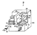
図1は、本発明が適用されるタグプリンタ10の全体構成を示す斜視図である。図中、タグ30の幅方向をX軸方向、ピッチ(長さ)方向をY軸方向として説明する。
【0009】
同図に示すように、タグプリンタ10は、ホッパー装置12、ゲート部材14、タグ繰り出し装置16、移送装置18、印字装置22及び制御装置24から大略構成されている。
【0010】
被印字媒体としての単葉タグ30、30、…(以下、単に「タグ」という)は、ゲート部材14とホッパー装置12との間に正確に揃えられて積層・保持され、タグ30は最下部の方から順にタグ繰り出し装置16によって繰り出され、移送装置18まで移送される。
【0011】
タグ繰り出し装置16は、タグ30の下面を吸着する3個の吸着パッド38A、38B、38Cと、該吸着パッド38A〜38Cを支持する図示しないブラケットとからなり、該ブラケットは、降下しながらゲート部材14の下方をくぐって移送装置18側に変位するようになっている。
前記タグ繰り出し装置16は最下部のタグ30を吸着パッド38A〜38Cで吸着し、ブラケットを変位させて移送装置18まで搬送する。ゲート部材14は上下に積層されたタグ30の重送を防止し、移送装置18に正確に一枚ずつのタグ30が移送される。そして、タグ30は、前記吸着パッド38A〜38Cの吸着が解除されて移送装置18に受け渡される。
【0012】
移送装置18は図示しないベルトコンベアを備え、タグ繰り出し装置16から受け取ったタグ30を印字装置22に移送する。
【0013】
印字装置22は移送されたタグ30に印字を行うもので、印字ヘッド72及びプラテンローラ74から大略構成されている。
【0014】
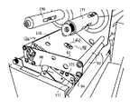
図2は印字装置22の構成を示す側面図で、図3は同様の上面図である。図2に示すように、プラテンローラ74は下部フレーム78の上端部に回転自在に配設されている。印字ヘッド72はヘッドブラケット76の先端部下側に支持され、該ヘッドブラケット76はヘッド軸80を支点として上部フレームの主要部を構成するサイドフレーム82と前記ゲート部材14との間に揺動自在に支持されている。
【0015】
前記サイドフレーム82と前記ゲート部材14との間には複数のガイドローラ92、92、…が回転自在に支持されると共に、ヘッドブラケット76の先端部、印字ヘッド72近傍にはガイドローラ94が回転自在に支持されている。
【0016】
カーボンリボン96は供給軸150(図15参照)に装着される供給リール(図示せず)からガイドローラ92にガイドされて印字ヘッド72とプラテンローラ74との間に搬送され、ガイドローラ94、92にガイドされて巻取軸151に装着される巻取リール(図示せず)に搬送される。
【0017】
前記ヘッド軸80には同軸上にヘッド軸プーリ84が設けられ、該ヘッド軸プーリ84は図3に示すようにゲート部材14内に収容されている。また、該ヘッド軸プーリ84はベルト86を介してモータプーリ88に接続され、該モータプーリ88には図示しないステッピングモータが接続されている。90はベルト86に付設されたテンションプーリで、ベルト86に所定のテンションを付与する。
そして、ベルト86の走行によってヘッドブラケット76が揺動すると、印字ヘッド72がプラテンローラ74に対して離接動する。即ち、ベルト86が矢印右方向に走行すると印字ヘッド72が閉じて印字を行い、ベルト86が矢印左方向に走行すると印字ヘッド72が開く。
【0018】
前記サイドフレーム82にはレバー98がピン100を支点として回動自在に支持され、レバー98の先端部には凹状のフック部98Aが形成されている。前記下部フレーム78には係合ピン102が設けられ、前記フック部98Aが係合ピン102に係合してヘッドブラケット76が閉位置に固定されるようになっている。
【0019】
また、前記ヘッドブラケット76の中央部にはロック用ピン104が設けられ、カーボンリボン96を交換する際には、図4に示す印字ヘッド72が閉じた状態から、ヘッドブラケット76を反時計方向に揺動させ印字ヘッド72を開ける。ヘッドブラケット76の揺動によりロック用ピン104がレバー98の下縁に当接して、レバー98のフック部98Aが係合ピン102から外れ、図5に示すように、ロック用ピン104がレバー98を押し上げて時計方向に回動させる。この、印字ヘッド72が開いた状態でカーボンリボン96を交換する。
【0020】
カーボンリボン96の交換が終了したら、ヘッドブラケット76を時計方向に揺動させ印字ヘッド72を閉じる。ヘッドブラケット76上のロック用ピン104の下降と共にレバー98が反時計方向に自重で回動し、図4に示すようにフック部98Aが契合ピン102に係合する。このように、印字ヘッド72を開けると自動的にヘッドブラケット76が下部フレーム78から解除され、印字ヘッド72を閉じると自動的にヘッドブラケット76が下部フレーム78に固定される。
【0021】
一方、タグ30を印字ヘッド72とプラテンローラ74との間に移送する際には、図4に示すように印字ヘッド72が閉じた状態から、図6に示すようにヘッドブラケット76をロック用ピン104がレバー98の下縁に当接しない程度に反時計方向に揺動させ、印字ヘッド72をタグ30に接触しない位置まで上昇させる。タグ30が印字ヘッド72とプラテンローラ74との間に移送されたら、ヘッドブラケット76を時計方向に揺動させて印字ヘッド72を閉じて、印字を行なうようになっている。
【0022】
次に、図7ないし図14を用いてヘッドブラケット76および印字ヘッド72の構成を説明する。まず、ヘッドブラケット76はブラケット本体110、ボトム部材111、印字ヘッド72から大略構成されている。また、前記印字ヘッド72は図13,図14に示す如く端面ヘッド112とヘッド取付部材113から大略構成されている。
図7はヘッドブラケット76の詳細な側面図、図8は同、上面図である。また、図9〜図14は、ヘッドブラケット76または印字ヘッド72を構成するブラケット本体110、ボトム部材111またはヘッド取付部材113の詳細な側面図ないし上面図である。
ブラケット本体110は板金折り曲げ加工等により、断面が略逆U字状、側面形状が、基端側(ヘッド軸80側)から先端側(印字ヘッド72側)に向けて幅が減少する略三角形状をなしている(図9、図10参照)。
【0023】
ボトム部材111は、図11、図12に示す如く、基端側ほぼ半分が前記ブラケット本体110と同様、断面が略逆U字状に折り曲げ形成され、ブラケット本体110と同じヘッド軸80に支持される軸穴152を備えている。
【0024】
また、該ボトム部材111の先端側ほぼ半分は、逆U字状部のうち底部が切取られた無底部114と、該無底部114を挟んで平行に対向する一対の側板部115、115となり、該各側板部115の先端には前述のガイドローラ94が支持されている。
【0025】
該ボトム部材111は、前記ブラケット本体110の内側に丁度収まる幅寸法を以て、基端側がブラケット本体110と同一のヘッド軸80(図示せず)に支持されるようになっている。
また、該ボトム部材111の側板部115には、端面ヘッド112のコーナー部(プラテンローラ74との接触点C)を中心として、2種類の異なる半径(r1,r2)からなる円弧状の穴よりなるガイド溝116,117が形成されている。また、前記各ガイド溝116,117の中間位置には、長方形の調整穴118が形成されている。
【0026】
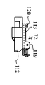
ヘッド取付部材113は、前述ボトム部材111の各側板部115の間に丁度収まる幅寸法を以て、断面が略U字状に折り曲げ形成され、上部には前後に離間して取付穴を有する取付部119,120が突出形成されている。そして、ヘッド取付部材113は、その底部側に端面ヘッド112を固定する固定構造を備え、端面ヘッド113の同一面内での傾き等を調整し、固定できるようになっている。
該ヘッド取付部材113は取付部119,120を前述ボトム部材111のガイド溝116,117に一致させ、固定ねじ121、シャフト122を以て前記ボトム部材111に取付けられる。そして、固定ねじ121,121を緩めた状態で、前記調整穴118にマイナス(−)ドライバを差し込み、その先端をテコのようにして、調整穴118の上側または下側辺と該調整穴118内のヘッド取付部材113の上辺または下辺との間隔をこじ開けるようにして広めると、ヘッド取付部材113は各ガイド溝116,117に沿って円弧を描くように相対移動する。このとき、端面ヘッド112はコーナー部(プラテンローラ74との接触点)Cが回転中心となる円弧を描くので、プラテンローラ74と前後に相対移動することなく、接触角のみが増減する。なお、各ガイド溝116,117の幅と、固定ねじ121、シャフト122の各径寸法は、互いに移動することが可能で、かつ、ガタつかないように、所定の精度を以て形成されている。そして、ヘッド角度を調節した後、固定ねじ121を締め付けることにより、ヘッド取付部材113はボトム部材111に固定される。
【0027】
本発明の第一の実施の形態は以上の如きもので、ヘッド取付部材113が内側に丁度収まる幅寸法に離間したボトム部材111の側板部115,115に、端面ヘッド112のコーナー部(プラテンローラに対する接点C)を中心とする異なる半径(r1,r2)の円弧からなるガイド溝116,117を設け、該ガイド溝116,117に一致させて、固定ねじ121、シャフト122を以てヘッド取付部材113を取付け、さらに側板部115に設けた調整穴118にマイナスドライバを差し込んでヘッド取付部材113を相対移動させるようにしたから、上述のようにプラテンローラ74に端面ヘッド112のコーナー部を当接させたまま、ヘッドの接触角を増減でき、このとき接触点Cが前後移動することなく、ヘッド角のみが増減するので、実際にタグ30に印字を行い、印字結果を見ながら角度調整できる。
【0028】
また、端面ヘッド112の片側で角度調整を行えば、印字ヘッド72の幅方向反対側でも反映されるので、調整の手間が省けるという効果を奏する。
【0029】
次に、本発明の第二の実施の形態を図16ないし図24を用いて詳述するに、前述したのと同一の構成要素には同一符号を付しその説明を省略するものとする。
【0030】
まず、126は本実施の形態で用いるヘッドブラケットを示し、該ヘッドブラケット126は、ブラケット本体130、ボトム部材131、前述の印字ヘッド72とから大略構成されている。
【0031】
図16はヘッドブラケット126および印字ヘッド72の詳細な側面図、図17は同、上面図である。また、図18、19はヘッドブラケット126を構成するブラケット本体130の各側面図および上面図、図20、21はヘッドブラケット126を構成するボトム部材131の各側面図および上面図である。
ブラケット本体130は、前述第一実施形態のブラケット本体110とほぼ同様に、断面略逆U字状、側面形状が、基端側(ヘッド軸80側)から先端側(印字ヘッド72側)に向けて幅が減少する略三角形状に形成されるものの、該ブラケット本体130には、底面部ほぼ中央に長円形の調整穴138が形成されている。
【0032】
ボトム部材131は、図20、図21に示す如く、前述のボトム部材111とほぼ同様に無底部134、一対の側板部135、135等を備えて構成されるものの、該ボトム部材131は底面部に無底部134側から2本の切り込みが形成され、中央が上側に逆L字状に折り曲げられたねじ座部139となり、該ねじ座部139にはマイナス(−)の頭部を備えた調整ねじ140が取り付けられている。
前記ねじ座部139の取付穴161(図16参照)は、該調整ねじ140が回転可能に遊嵌して挿通され、調整ねじ140の頭部がこの中に抜け止めされている。そして、該調整ねじ140先端のねじ部はヘッド取付部材113のねじ穴(図23中に示す160)に螺合するようになっている。
また、該ボトム部材131は、前記ブラケット本体130の内側に丁度収まるように、同一のヘッド軸80に支持される。そして、前記各側板部135には、前述の第一実施形態のガイド溝116,117と同様のガイド溝136,137が形成され、該各カイド溝136、137に固定ねじ121,シャフト122を介して前述第一の実施形態と同様に印字ヘッド72(端面ヘッド112およびヘッド取付部材113)が取付けられている。
【0033】
141はブラケット本体130とボトム部材131の間に、前記シャフト122に巻き付けるように配設されたばね(トルクスプリング)で、該ばね141は、ブラケット本体130とボトム部材131の先端側を離間させる方向に常時付勢している。そして、調整ねじ140を回転させて前記ねじ穴151内からねじ部が退出するときに、ねじ頭をねじ座部139に当接させる。ねじ頭はこの時ねじ座部139に対して傾斜することにより、円弧型のカーブを直線方向の移動に変換する。
【0034】
本実施の形態は以上の構成を有するもので、前記調節ねじ140のねじ先端が印字ヘッド72の基端側(ヘッド軸80側)に形成したねじ穴160に螺合するように組み立てられ、固定ねじ121,121を緩めた状態で、該調節ねじ140をドライバ等で回転させるとねじ先端が印字ヘッド72の基端側を遠ざけ、または引き寄せるようになり、印字ヘッド72はヘッド取付部材113がガイド溝136,137に沿って移動するので、端面ヘッド112はコーナー部(プラテンローラ74との接触点)が回転中心となる円弧を描いて、プラテンローラ74と前後に相対移動することなく、接触角のみが増減する。
【0035】
ここで、本実施の形態では調節ねじ140を印字ヘッド72の幅方向中央に配設し、ばね141がヘッド取付部材113の左右を均等に押圧するようにしたので、調節ねじ141を回転させると印字ヘッド72のヘッド角度が左右同時に均一に移動できるといった効果を奏する。
【0036】
なお、本実施の形態において、ボトム部材131に第一の実施の形態で説明した調整穴118と同様の長方形の穴が描かれているが、調節穴として用いるものではない。
【0037】
また、各実施の形態では本発明をタグプリンタに適用した例を説明したが、他にカード用プリンタなどの端面ヘッドを用いる感熱記録装置に適用してもよい。
【0038】
【発明の効果】
以上説明した通り、本発明によれば、調節手段を端面ヘッドの幅方向中央に配設し、ばねが端面ヘッドの左右を均等に押圧するようにしたので、ねじを回転させると、端面ヘッドをプラテンローラに左右均一に押しつけた状態で、端面ヘッドのヘッド角度を左右同時に均一に移動でき、印字状態を見ながらヘッド角度を調整できるので操作性がよいといった効果を奏する。
【図面の簡単な説明】
【図1】本発明の印字装置が適用されたタグプリンタの全体構成を示す斜視図である。
【図2】印字装置の構成を示す側面図である。
【図3】印字装置の構成を示す上面図である。
【図4】印字ヘッドが閉じた状態を示す説明図である。
【図5】印字ヘッドが開いた状態を示す説明図である。
【図6】印字ヘッドがタグに接触しない位置まで上昇した状態を示す説明図である。
【図7】第一の実施の形態に係るヘッドブラケットの構成を示す側面図である。
【図8】同、ヘッドブラケットの構成を示す上面図である。
【図9】同、ブラケット本体の構成を示す側面図である。
【図10】同、ブラケット本体の構成を示す上面図である。
【図11】同、ボトム部材の構成を示す側面図である。
【図12】同、ボトム部材の構成を示す上面図である。
【図13】同、印字ヘッドの構成を示す側面図である。
【図14】同、印字ヘッドの構成を示す上面図である。
【図15】同、タグプリンタのヘッドブラケット構成を示す斜視図である。
【図16】第二の実施の形態に係るヘッドブラケットの構成を示す側面図である。
【図17】同、ヘッドブラケットの構成を示す上面図である。
【図18】同、ブラケット本体の構成を示す側面図である。
【図19】同、ブラケット本体の構成を示す上面図である。
【図20】同、ボトム部材の構成を示す側面図である。
【図21】同、ボトム部材の構成を示す上面図である。
【図22】同、印字ヘッドの構成を示す側面図である。
【図23】同、印字ヘッドの構成を示す上面図である。
【図24】同、タグプリンタのヘッドブラケット構成を示す斜視図である。
【符号の説明】
10…タグプリンタ、30…タグ、72…印字ヘッド、74…プラテンローラ、76,126…ヘッドブラケット、110,130…ブラケット本体、111,131…ボトム部材、112…端面ヘッド、113…ヘッド取付部材、116,117,136,137…ガイド溝、118…調節穴、121…固定ねじ、140…調節ねじ、141…ばね[0001]
BACKGROUND OF THE INVENTION
The present invention relates to a mounting structure for an end face head (corner head) used in a recording apparatus that performs thermal recording on a single-leaf tag, a card, or the like.
[0002]
[Prior art]
Conventionally, in a thermal recording apparatus using a single-leaf tag or a card as a printing medium, since these non-printing media cannot be bent in the transport direction, an end face head (corner head) has been used. The end face head was completely fixed to the head bracket with a fixing screw.
[0003]
[Problems to be solved by the invention]
By the way, in the conventional thermal recording apparatus, it is difficult to adjust the contact angle in a state where the left and right ends of the end face head are pressed uniformly against the platen roller.
[0004]
However, the optimum contact angle for printing differs depending on the variation of each head and printing conditions, and it is necessary to adjust the contact angle of the end face head.
[0005]
The present invention has been made to solve the above-mentioned problems of the prior art, and its object is to attach a thermal recording head that can adjust the contact angle while the end face head is pressed uniformly against the platen roller. Is to provide.
[0006]
[Means for Solving the Problems]
In order to solve the above problems, the features of the configuration adopted by the present invention are the head bracket,
The end face head is spaced apart in the width direction to form a pair, a guide part comprising arcs of different radii around the contact point of the end face head with the platen roller, and a center part of the head bracket, the end face head being An adjustment means consisting of a spring and a feed screw that is displaced along the guide part and increases or decreases only the contact angle with the platen roller without moving the contact point back and forth while the corner part of the end face head is in contact with the platen roller. And fixing means for fixing the end face head at a predetermined position.
[0008]
DETAILED DESCRIPTION OF THE INVENTION
Preferred embodiments to which the present invention is applied will be described below in detail with reference to the accompanying drawings.
FIG. 1 is a perspective view showing the overall configuration of a
[0009]
As shown in the figure, the
[0010]
Single-
[0011]
The tag feeding device 16 includes three
The tag feeding device 16 sucks the
[0012]
The
[0013]
The
[0014]
2 is a side view showing the configuration of the
[0015]
A plurality of
[0016]
The
[0017]
The
When the
[0018]
A
[0019]
Further, a
[0020]
When the replacement of the
[0021]
On the other hand, when the
[0022]
Next, the configuration of the
7 is a detailed side view of the
The bracket
[0023]
As shown in FIGS. 11 and 12, the
[0024]
Also, almost half of the bottom side of the
[0025]
The
Further, the
[0026]
The
The
[0027]
The first embodiment of the present invention is as described above, and the corner portion (platen roller) of the
[0028]
Further, if the angle adjustment is performed on one side of the
[0029]
Next, a second embodiment of the present invention will be described in detail with reference to FIGS. 16 to 24. The same components as those described above are denoted by the same reference numerals, and the description thereof will be omitted.
[0030]
First,
[0031]
16 is a detailed side view of the
The bracket
[0032]
As shown in FIGS. 20 and 21, the
An attachment hole 161 (see FIG. 16) of the
Further, the
[0033]
[0034]
The present embodiment has the above configuration, and is assembled and fixed so that the screw tip of the adjusting
[0035]
Here, in this embodiment, the
[0036]
In the present embodiment, the
[0037]
In each embodiment, an example in which the present invention is applied to a tag printer has been described. Alternatively, the present invention may be applied to a thermal recording apparatus using an end face head such as a card printer.
[0038]
【The invention's effect】
As described above, according to the present invention, the adjusting means is disposed at the center in the width direction of the end face head, and the spring presses the left and right sides of the end face head evenly. in a state of pressing the right and left uniformly to the platen roller, the head angle of the end face head right and left can at the same time uniformly moving, an effect such good operability can be adjusted to the head angle while watching the printing state.
[Brief description of the drawings]
FIG. 1 is a perspective view showing an overall configuration of a tag printer to which a printing apparatus of the present invention is applied.
FIG. 2 is a side view illustrating a configuration of a printing apparatus.
FIG. 3 is a top view illustrating a configuration of a printing apparatus.
FIG. 4 is an explanatory diagram illustrating a state in which a print head is closed.
FIG. 5 is an explanatory diagram illustrating a state in which a print head is opened.
FIG. 6 is an explanatory diagram showing a state where the print head has been raised to a position where it does not contact the tag.
FIG. 7 is a side view showing the configuration of the head bracket according to the first embodiment.
FIG. 8 is a top view showing the configuration of the head bracket.
FIG. 9 is a side view showing the configuration of the bracket body.
FIG. 10 is a top view showing the configuration of the bracket body.
FIG. 11 is a side view showing the configuration of the bottom member.
FIG. 12 is a top view showing the configuration of the bottom member.
FIG. 13 is a side view showing the configuration of the print head.
FIG. 14 is a top view showing the configuration of the print head.
FIG. 15 is a perspective view showing a head bracket configuration of the tag printer.
FIG. 16 is a side view showing a configuration of a head bracket according to a second embodiment.
FIG. 17 is a top view showing the configuration of the head bracket.
FIG. 18 is a side view showing the configuration of the bracket body.
FIG. 19 is a top view showing the configuration of the bracket body.
FIG. 20 is a side view showing the configuration of the bottom member.
FIG. 21 is a top view showing the configuration of the bottom member.
FIG. 22 is a side view showing the configuration of the print head.
FIG. 23 is a top view showing the configuration of the print head.
FIG. 24 is a perspective view showing a head bracket configuration of the tag printer.
[Explanation of symbols]
DESCRIPTION OF
Claims (1)
Priority Applications (1)
| Application Number | Priority Date | Filing Date | Title |
|---|---|---|---|
| JP2002190364A JP4087649B2 (en) | 2002-06-28 | 2002-06-28 | Mounting structure of thermal recording head |
Applications Claiming Priority (1)
| Application Number | Priority Date | Filing Date | Title |
|---|---|---|---|
| JP2002190364A JP4087649B2 (en) | 2002-06-28 | 2002-06-28 | Mounting structure of thermal recording head |
Publications (2)
| Publication Number | Publication Date |
|---|---|
| JP2004034323A JP2004034323A (en) | 2004-02-05 |
| JP4087649B2 true JP4087649B2 (en) | 2008-05-21 |
Family
ID=31700299
Family Applications (1)
| Application Number | Title | Priority Date | Filing Date |
|---|---|---|---|
| JP2002190364A Expired - Lifetime JP4087649B2 (en) | 2002-06-28 | 2002-06-28 | Mounting structure of thermal recording head |
Country Status (1)
| Country | Link |
|---|---|
| JP (1) | JP4087649B2 (en) |
Families Citing this family (1)
| Publication number | Priority date | Publication date | Assignee | Title |
|---|---|---|---|---|
| KR100699478B1 (en) * | 2005-06-17 | 2007-03-26 | 삼성전자주식회사 | Print head assembly and image forming apparatus having the same |
-
2002
- 2002-06-28 JP JP2002190364A patent/JP4087649B2/en not_active Expired - Lifetime
Also Published As
| Publication number | Publication date |
|---|---|
| JP2004034323A (en) | 2004-02-05 |
Similar Documents
| Publication | Publication Date | Title |
|---|---|---|
| KR950007740B1 (en) | Printer | |
| JPS62152768A (en) | Label feeder | |
| US5882126A (en) | Laterally adjustable print head | |
| JP4087649B2 (en) | Mounting structure of thermal recording head | |
| USRE38473E1 (en) | Printer with floating print head with alignment surfaces to position printhead | |
| JPH0335563Y2 (en) | ||
| JP3142147B2 (en) | Printer paper feed mechanism | |
| JP4019297B2 (en) | Thermal printer | |
| JP4074720B2 (en) | Tag printer | |
| JPH0776142A (en) | Printer | |
| JP4140074B2 (en) | Ink ribbon feeder | |
| JP3503567B2 (en) | Back tension adjustment mechanism for printer printing paper | |
| JP3769865B2 (en) | Winding mechanism and printer using the same | |
| JP2963618B2 (en) | Thermal printer | |
| JPH0761076A (en) | Printer device | |
| JP3739970B2 (en) | Thermal transfer printer | |
| JPH0546926Y2 (en) | ||
| JPH0761075A (en) | Printer device | |
| JP2607324B2 (en) | Web feeder | |
| JP3621299B2 (en) | Thermal transfer printer | |
| JP4540187B2 (en) | Thermal printer | |
| JP3088800B2 (en) | Printing device | |
| JP3775949B2 (en) | Thermal transfer printer | |
| JPH085172Y2 (en) | Sheet roll holding mechanism | |
| JPH0811375A (en) | Form-conveying device in printer |
Legal Events
| Date | Code | Title | Description |
|---|---|---|---|
| A621 | Written request for application examination |
Free format text: JAPANESE INTERMEDIATE CODE: A621 Effective date: 20050623 |
|
| A977 | Report on retrieval |
Free format text: JAPANESE INTERMEDIATE CODE: A971007 Effective date: 20071005 |
|
| A131 | Notification of reasons for refusal |
Free format text: JAPANESE INTERMEDIATE CODE: A131 Effective date: 20071018 |
|
| A521 | Request for written amendment filed |
Free format text: JAPANESE INTERMEDIATE CODE: A523 Effective date: 20071211 |
|
| TRDD | Decision of grant or rejection written | ||
| A01 | Written decision to grant a patent or to grant a registration (utility model) |
Free format text: JAPANESE INTERMEDIATE CODE: A01 Effective date: 20080125 |
|
| A61 | First payment of annual fees (during grant procedure) |
Free format text: JAPANESE INTERMEDIATE CODE: A61 Effective date: 20080221 |
|
| FPAY | Renewal fee payment (event date is renewal date of database) |
Free format text: PAYMENT UNTIL: 20110228 Year of fee payment: 3 |
|
| R150 | Certificate of patent or registration of utility model |
Ref document number: 4087649 Country of ref document: JP Free format text: JAPANESE INTERMEDIATE CODE: R150 Free format text: JAPANESE INTERMEDIATE CODE: R150 |
|
| S531 | Written request for registration of change of domicile |
Free format text: JAPANESE INTERMEDIATE CODE: R313531 |
|
| FPAY | Renewal fee payment (event date is renewal date of database) |
Free format text: PAYMENT UNTIL: 20110228 Year of fee payment: 3 |
|
| R350 | Written notification of registration of transfer |
Free format text: JAPANESE INTERMEDIATE CODE: R350 |
|
| FPAY | Renewal fee payment (event date is renewal date of database) |
Free format text: PAYMENT UNTIL: 20110228 Year of fee payment: 3 |
|
| FPAY | Renewal fee payment (event date is renewal date of database) |
Free format text: PAYMENT UNTIL: 20120229 Year of fee payment: 4 |
|
| R250 | Receipt of annual fees |
Free format text: JAPANESE INTERMEDIATE CODE: R250 |
|
| FPAY | Renewal fee payment (event date is renewal date of database) |
Free format text: PAYMENT UNTIL: 20120229 Year of fee payment: 4 |
|
| S533 | Written request for registration of change of name |
Free format text: JAPANESE INTERMEDIATE CODE: R313533 |
|
| FPAY | Renewal fee payment (event date is renewal date of database) |
Free format text: PAYMENT UNTIL: 20120229 Year of fee payment: 4 |
|
| R360 | Written notification for declining of transfer of rights |
Free format text: JAPANESE INTERMEDIATE CODE: R360 |
|
| FPAY | Renewal fee payment (event date is renewal date of database) |
Free format text: PAYMENT UNTIL: 20120229 Year of fee payment: 4 |
|
| FPAY | Renewal fee payment (event date is renewal date of database) |
Free format text: PAYMENT UNTIL: 20120229 Year of fee payment: 4 |
|
| R360 | Written notification for declining of transfer of rights |
Free format text: JAPANESE INTERMEDIATE CODE: R360 |
|
| R371 | Transfer withdrawn |
Free format text: JAPANESE INTERMEDIATE CODE: R371 |
|
| S533 | Written request for registration of change of name |
Free format text: JAPANESE INTERMEDIATE CODE: R313533 |
|
| FPAY | Renewal fee payment (event date is renewal date of database) |
Free format text: PAYMENT UNTIL: 20120229 Year of fee payment: 4 |
|
| R350 | Written notification of registration of transfer |
Free format text: JAPANESE INTERMEDIATE CODE: R350 |
|
| FPAY | Renewal fee payment (event date is renewal date of database) |
Free format text: PAYMENT UNTIL: 20120229 Year of fee payment: 4 |
|
| FPAY | Renewal fee payment (event date is renewal date of database) |
Free format text: PAYMENT UNTIL: 20130228 Year of fee payment: 5 |
|
| R250 | Receipt of annual fees |
Free format text: JAPANESE INTERMEDIATE CODE: R250 |
|
| FPAY | Renewal fee payment (event date is renewal date of database) |
Free format text: PAYMENT UNTIL: 20140228 Year of fee payment: 6 |
|
| R250 | Receipt of annual fees |
Free format text: JAPANESE INTERMEDIATE CODE: R250 |
|
| R250 | Receipt of annual fees |
Free format text: JAPANESE INTERMEDIATE CODE: R250 |
|
| R250 | Receipt of annual fees |
Free format text: JAPANESE INTERMEDIATE CODE: R250 |
|
| R250 | Receipt of annual fees |
Free format text: JAPANESE INTERMEDIATE CODE: R250 |
|
| R250 | Receipt of annual fees |
Free format text: JAPANESE INTERMEDIATE CODE: R250 |
|
| R250 | Receipt of annual fees |
Free format text: JAPANESE INTERMEDIATE CODE: R250 |
|
| R250 | Receipt of annual fees |
Free format text: JAPANESE INTERMEDIATE CODE: R250 |
|
| R250 | Receipt of annual fees |
Free format text: JAPANESE INTERMEDIATE CODE: R250 |
|
| R250 | Receipt of annual fees |
Free format text: JAPANESE INTERMEDIATE CODE: R250 |
|
| R250 | Receipt of annual fees |
Free format text: JAPANESE INTERMEDIATE CODE: R250 |
|
| EXPY | Cancellation because of completion of term |