JP4085239B2 - Gasification method and gasification apparatus - Google Patents
Gasification method and gasification apparatus Download PDFInfo
- Publication number
- JP4085239B2 JP4085239B2 JP2002034173A JP2002034173A JP4085239B2 JP 4085239 B2 JP4085239 B2 JP 4085239B2 JP 2002034173 A JP2002034173 A JP 2002034173A JP 2002034173 A JP2002034173 A JP 2002034173A JP 4085239 B2 JP4085239 B2 JP 4085239B2
- Authority
- JP
- Japan
- Prior art keywords
- gasification furnace
- slurry
- gas
- gasification
- product gas
- Prior art date
- Legal status (The legal status is an assumption and is not a legal conclusion. Google has not performed a legal analysis and makes no representation as to the accuracy of the status listed.)
- Expired - Fee Related
Links
Images


Classifications
-
- C—CHEMISTRY; METALLURGY
- C10—PETROLEUM, GAS OR COKE INDUSTRIES; TECHNICAL GASES CONTAINING CARBON MONOXIDE; FUELS; LUBRICANTS; PEAT
- C10J—PRODUCTION OF PRODUCER GAS, WATER-GAS, SYNTHESIS GAS FROM SOLID CARBONACEOUS MATERIAL, OR MIXTURES CONTAINING THESE GASES; CARBURETTING AIR OR OTHER GASES
- C10J3/00—Production of combustible gases containing carbon monoxide from solid carbonaceous fuels
- C10J3/46—Gasification of granular or pulverulent flues in suspension
- C10J3/466—Entrained flow processes
-
- C—CHEMISTRY; METALLURGY
- C10—PETROLEUM, GAS OR COKE INDUSTRIES; TECHNICAL GASES CONTAINING CARBON MONOXIDE; FUELS; LUBRICANTS; PEAT
- C10J—PRODUCTION OF PRODUCER GAS, WATER-GAS, SYNTHESIS GAS FROM SOLID CARBONACEOUS MATERIAL, OR MIXTURES CONTAINING THESE GASES; CARBURETTING AIR OR OTHER GASES
- C10J3/00—Production of combustible gases containing carbon monoxide from solid carbonaceous fuels
- C10J3/46—Gasification of granular or pulverulent flues in suspension
- C10J3/54—Gasification of granular or pulverulent fuels by the Winkler technique, i.e. by fluidisation
- C10J3/56—Apparatus; Plants
-
- C—CHEMISTRY; METALLURGY
- C10—PETROLEUM, GAS OR COKE INDUSTRIES; TECHNICAL GASES CONTAINING CARBON MONOXIDE; FUELS; LUBRICANTS; PEAT
- C10J—PRODUCTION OF PRODUCER GAS, WATER-GAS, SYNTHESIS GAS FROM SOLID CARBONACEOUS MATERIAL, OR MIXTURES CONTAINING THESE GASES; CARBURETTING AIR OR OTHER GASES
- C10J3/00—Production of combustible gases containing carbon monoxide from solid carbonaceous fuels
- C10J3/72—Other features
- C10J3/723—Controlling or regulating the gasification process
-
- C—CHEMISTRY; METALLURGY
- C10—PETROLEUM, GAS OR COKE INDUSTRIES; TECHNICAL GASES CONTAINING CARBON MONOXIDE; FUELS; LUBRICANTS; PEAT
- C10J—PRODUCTION OF PRODUCER GAS, WATER-GAS, SYNTHESIS GAS FROM SOLID CARBONACEOUS MATERIAL, OR MIXTURES CONTAINING THESE GASES; CARBURETTING AIR OR OTHER GASES
- C10J2200/00—Details of gasification apparatus
- C10J2200/15—Details of feeding means
-
- C—CHEMISTRY; METALLURGY
- C10—PETROLEUM, GAS OR COKE INDUSTRIES; TECHNICAL GASES CONTAINING CARBON MONOXIDE; FUELS; LUBRICANTS; PEAT
- C10J—PRODUCTION OF PRODUCER GAS, WATER-GAS, SYNTHESIS GAS FROM SOLID CARBONACEOUS MATERIAL, OR MIXTURES CONTAINING THESE GASES; CARBURETTING AIR OR OTHER GASES
- C10J2300/00—Details of gasification processes
- C10J2300/09—Details of the feed, e.g. feeding of spent catalyst, inert gas or halogens
- C10J2300/0913—Carbonaceous raw material
- C10J2300/095—Exhaust gas from an external process for purification
-
- C—CHEMISTRY; METALLURGY
- C10—PETROLEUM, GAS OR COKE INDUSTRIES; TECHNICAL GASES CONTAINING CARBON MONOXIDE; FUELS; LUBRICANTS; PEAT
- C10J—PRODUCTION OF PRODUCER GAS, WATER-GAS, SYNTHESIS GAS FROM SOLID CARBONACEOUS MATERIAL, OR MIXTURES CONTAINING THESE GASES; CARBURETTING AIR OR OTHER GASES
- C10J2300/00—Details of gasification processes
- C10J2300/16—Integration of gasification processes with another plant or parts within the plant
- C10J2300/169—Integration of gasification processes with another plant or parts within the plant with water treatments
-
- C—CHEMISTRY; METALLURGY
- C10—PETROLEUM, GAS OR COKE INDUSTRIES; TECHNICAL GASES CONTAINING CARBON MONOXIDE; FUELS; LUBRICANTS; PEAT
- C10J—PRODUCTION OF PRODUCER GAS, WATER-GAS, SYNTHESIS GAS FROM SOLID CARBONACEOUS MATERIAL, OR MIXTURES CONTAINING THESE GASES; CARBURETTING AIR OR OTHER GASES
- C10J2300/00—Details of gasification processes
- C10J2300/18—Details of the gasification process, e.g. loops, autothermal operation
- C10J2300/1807—Recycle loops, e.g. gas, solids, heating medium, water
Landscapes
- Chemical & Material Sciences (AREA)
- Engineering & Computer Science (AREA)
- Combustion & Propulsion (AREA)
- Oil, Petroleum & Natural Gas (AREA)
- Organic Chemistry (AREA)
- Processing Of Solid Wastes (AREA)
- Gasification And Melting Of Waste (AREA)
- Organic Low-Molecular-Weight Compounds And Preparation Thereof (AREA)
- Industrial Gases (AREA)
Description
【0001】
【発明の属する技術分野】
本発明は、固体燃料のガス化技術に係り、特に、気流層方式のガス化炉を用いた固体燃料のガス化技術に関する。
【0002】
【従来の技術】
固体燃料、例えば石炭などの固体の炭化水素などを微粉砕し、酸素により部分燃焼させてガスを生成するガス化装置としては、固定層、流動層、そして気流層または噴流層と称されるものなど様々な方式のものが提案されている。これらのなかで、気流層または噴流層と称されている方式は、例えば1500℃といったような比較的高温でのガス化炉の運転が可能であり、燃料のガスヘの変換効率が他の方式に比べて高い。また、比較的高温でのガス化炉の運転が可能であることにより、炭化水素などの固体燃料中の灰分を溶融することができるため、灰分をスラグとして回収して再利用することもできる。このような気流層方式のガス化炉が、特公平5−25919号公報、特開昭59−84980号公報などに提案されている。
【0003】
ここで、このような気流層方式のガス化炉を備えたガス化装置では、ガス化炉内で生成されガス化炉から排出された生成ガスは、未反応の可燃成分、例えば未反応のチャーやタールなどの炭素分などを含む煤塵を同伴している。このため、この生成ガスに同伴される未反応の可燃成分をガス化炉に再供給して、可燃成分をできるだけ利用し、燃料のガスへの変換効率を向上する構成のガス化装置が、特開昭58−138790号公報、特開昭60−260689号公報、特開昭61−292号公報、特開昭62−131094号公報、特許第2719424号公報、特開平7−278575号公報、特開2000−328074号公報などに提案されている。
【0004】
特開昭58−138790号公報や特開平7−278575号公報に提案されているようなガス化装置では、ガス化炉として、筒状に形成されたガス化炉の一方の端部側に生成ガスの出口が設けられ、他方の端部側に燃料や酸素または空気を供給するバーナが設けられた構成のガス化炉を有している。そして、ガス化炉の出口から排出された生成ガスに同伴された未反応の可燃成分を含む煤塵を生成ガスから回収し、この回収した煤塵と、微粉砕された石炭などの固形燃料などとを混合してスラリとしている。そして、このスラリを、燃料としてポンプなどでガス化炉の運転圧力以上に加圧してガス化炉に供給している。このようなガス化装置では、生成ガスから回収した煤塵と共に微粉砕した固体燃料をスラリとしてガス化炉に供給するため、ガス化炉内に供給された水分によって燃料の発熱量が低下してしまう。
【0005】
一方、特開2000−328074号公報などに提案されているようなガス化装置では、微粉砕された粉体状または粒体状の固体燃料は、固体燃料の搬送用の気体によりガス化炉内に気流搬送される。一方、微粉砕した燃料を生成ガスに同伴する煤塵は、サイクロン及びフィルタなどにより生成ガスから除去されると共に回収され、この回収された乾燥状態の煤塵は、ロックホッパを介してガス化炉の運転圧力以上に加圧してガス化炉に再供給される。したがって、燃料の供給や生成ガスから回収した煤塵の再供給において、ガス化炉内に水分が供給されないため、燃料の発熱量の低下を抑制できる。しかし、このようなガス化装置では、生成ガスから回収した煤塵をガス化炉に再供給するのにロックホッパが必要となるため、装置のコストが増大してしまう。
【0006】
これに対して、特開昭60−260689号公報、特開昭61−292号公報、特開昭62−131094号公報、特許第2719424号公報などに提案されているようなガス化装置では、ガス化炉として、筒状に形成されたガス化炉の一方の端部側に生成ガスの出口が設けられ、他方の端部側に燃料や酸素または空気を供給するバーナが設けられた構成のガス化炉を有しており、固体燃料は、気流搬送によりバーナを介してガス化炉に供給される。一方、ガス化炉から排出された生成ガスに同伴する煤塵は、生成ガスから回収されてスラリ化され、この煤塵を含むスラリは、ポンプなどでガス化炉の運転圧力以上に加圧されて、ガス化炉のバーナが設けられた段部に再供給される。このようなガス化装置であれば、固体燃料は、気流搬送によりガス化炉に供給されるため、燃料の発熱量の減少、つまりガス化炉内の温度の低下を低減できる。
【0007】
また、特公昭57−17914号公報には、流動層方式のガス化炉を備えたガス化装置において、生成ガスに同伴されたチャーやタールなどを含む煤塵を回収して生成したスラリを、ガス化炉下部のチャー燃焼帯域に再供給することが記載されている。
【0008】
【発明が解決しようとする課題】
ところで、従来のガス化装置では、ガス化炉で生成された生成ガスの温度をこの生成ガスが送られる設備や機器類が要求する温度に冷却するため、ガス化炉の出口に連続する生成ガスの流路を有する冷却器を設け、ガス化炉から排出された生成ガスを冷却している。例えば、生成ガスを脱硫装置などで処理する場合、一般に脱硫処理は常温で行われるため、生成ガスを脱硫装置で常温にできるように冷却する必要がある。このような生成ガスを冷却する冷却器としては、流路を通流する水や蒸気などの流体と生成ガスとの間で熱交換を行うことで生成ガスを冷却するボイラ式の冷却器が用いられている。
【0009】
このとき、ガス化炉内から排出される生成ガスの温度によっては、ガス化炉内から排出される生成ガスに同伴された灰分の融解によってスラグが生成される場合がある。このため、冷却器として、生成ガスの流路内に生成ガスと熱交換を行う流体が通流する管路を複数配置した構造の冷却器を用いると、流体が通流する管路の隙間などにスラグが付着し、生成ガスの流路を閉塞してしまう場合がある。そこで、ガス化炉から排出される生成ガスの温度が、スラグが生成されるような温度になる可能性のあるガス化装置では、スラグによる流路の閉塞を防止するため、生成ガスの流路を画成する壁面に生成ガスと熱交換を行う流体が通流する流路を設けた構造、例えば水冷壁構造やジャケット構造の冷却器をガス化炉の出口に連結している。
【0010】
このような水冷壁構造やジャケット構造などの冷却器は、熱交換効率つまり冷却効率が生成ガスの流路内に複数の管路を配置した構造の冷却器に比べて低いため、冷却器が大型化してしまう。例えば、数メートル程度の高さのガス化炉に対して数十メートルの高さの冷却器を設置しなければならない場合がある。このようなガス化装置に設けられた水冷壁構造やジャケット構造などの冷却器が、ガス化装置の大型化やコストの増大などを招いている。このため、ガス化炉から排出される生成ガスの温度を低下させることにより、水冷壁構造やジャケット構造などの冷却器を小型化することが望まれている。
【0011】
これに対して本願の発明者らは、ガス化炉から排出された生成ガスから回収した煤塵で生成したスラリをガス化炉の生成ガスの出口側に供給し、このガス化炉の生成ガスの出口側に供給されたスラリの水分の蒸発により、ガス化炉から排出される生成ガスの温度を低下させることを考えている。しかし、スラリをガス化炉の生成ガスの出口側に供給すると、供給されたスラリは生成ガスに同伴されてガス化炉から排出されてしまうことになる。このため、従来の煤塵を含むスラリをガス化炉に再供給するガス化装置に比べ、スラリに含まれる未反応の可燃成分のガス化炉内での滞留時間が短く、この未反応の可燃成分がガス化炉内で反応し難くなり、燃料のガスへの変換効率を向上できなくなる。したがって、燃料のガスへの変換効率を向上しながらガス化炉から排出される生成ガスの温度を低下させる必要がある。
【0012】
本発明の課題は、燃料のガスへの変換効率を向上しながらガス化炉から排出される生成ガスの温度を低下させることにある。
【0013】
【課題を解決するための手段】
本発明のガス化方法は、固体燃料を部分燃焼させてガスを生成するガス化炉の生成ガスの出口側の部分に、この出口から排出された生成ガスに同伴された未反応の可燃成分を含む煤塵を回収して生成したスラリを供給し、この供給されたスラリを、ガス化炉内の出口に向かう生成ガスの流れである上昇流に対向する方向に流すことにより上記課題を解決する。
【0014】
このような構成とすることにより、スラリがガス化炉の生成ガスの出口側部分に供給されることにより、スラリ中の水分によってガス化炉から排出される生成ガスの温度を低下できる。さらに、ガス化炉内に供給されたスラリを、出口に向かうガス化炉内の生成ガスの流れに対向する方向に流すことにより、スラリに含まれる未反応の可燃成分がガス化炉内に留まる時間を長くでき、スラリに含まれる未反応の可燃成分の反応量を増加できる。したがって、燃料のガスへの変換効率を向上しながらガス化炉から排出される生成ガスの温度を低下できる。
【0015】
さらに、ガス化炉が、このガス化炉内に固体燃料を供給する下段バーナと、ガス化炉の下段バーナよりも出口側の部分に設けられ、ガス化炉内に固体燃料を供給すると共にガス化炉内に下降流を形成する上段バーナとを有し、スラリを、ガス化炉の上段バーナが設けられた段部に供給する。これにより、ガス化炉の出口側の部分に供給されたスラリが、上段バーナによって形成された下降流に同伴されるため、スラリをガス化炉内の出口に向かう生成ガスの流れである上昇流に対向する方向に容易に流すことができる。
【0016】
また、スラリをガス化炉内に噴出し、ガス化炉内に出口に向かう生成ガスの流れである上昇流に対向する方向への流れを形成することが好ましい。これによれば、上段バーナによって下降流を形成しなくても、ガス化炉内の生成ガスの流れである上昇流に対向させて、スラリを出口に向かう生成ガスの流れである上昇流に対向する方向に流すことができる。
【0017】
さらに、本発明のガス化装置は、固体燃料を部分燃焼させてガスを生成するガス化炉と、このガス化炉で生成された生成ガスが通流する生成ガス流路と、この生成ガス流路に設けられて生成ガスに同伴された未反応の可燃成分を含む煤塵を回収し、この回収された煤塵からスラリを生成するスラリ生成手段と、このスラリ生成手段で生成したスラリを加圧して搬送するポンプと、このポンプによってスラリ生成手段から搬送されたスラリをガス化炉内に供給するノズルとを備え、このノズルは、ガス化炉の生成ガスの出口側の部分に設けられており、ノズルからガス化炉内に供給されたスラリは、出口に向かうガス化炉内の生成ガスの流れである上昇流に対向する方向に流れる構成とすることにより上記課題を解決する。
【0018】
このような構成とすることにより、スラリがガス化炉の生成ガスの出口側部分に供給されることにより、スラリ中の水分でガス化炉から排出される生成ガスの温度を低下できる。さらに、ノズルからガス化炉内に供給されたスラリが、出口に向かうガス化炉内の生成ガスの流れに対向する方向に流れることにより、スラリに含まれる未反応の可燃成分がガス化炉内に留まる時間を長くでき、スラリに含まれる未反応の可燃成分の反応量を増加できる。したがって、燃料のガスへの変換効率を向上しながらガス化炉から排出される生成ガスの温度を低下できる。
【0019】
さらに、ガス化炉は、このガス化炉内に固体燃料を供給する下段バーナと、ガス化炉の下段バーナよりも出口側の部分に設けられ、ガス化炉内に固体燃料を供給すると共にガス化炉内に下降流を形成する上段バーナとを有し、ノズルは、ガス化炉の上段バーナが設けられた段部に設けられた構成とする。このように、上段バーナと下段バーナを有する2段バーナ式のガス化炉の上段バーナが設けられた段部にノズルを設ければ、ノズルからガス化炉内に供給されたスラリは、上段バーナによって形成された下降流に同伴されて流れるため、スラリを出口に向かうガス化炉内の生成ガスの流れである上昇流に対向する方向に容易に流すことができる。
【0020】
また、スラリ生成手段は、生成ガス流路を通流する生成ガスを水またはアルカリ溶液で洗浄して生成ガスに同伴された煤塵を生成ガスから除去して回収する洗浄器と、この洗浄器で回収された煤塵を含む洗浄排水から水の一部を除去してスラリ中の水の量を調整する脱水機とを有する構成とする。このような構成とすれば、煤塵を含むスラリを生成する際に、煤塵に水を添加するための機器類を設ける必要がないので好ましい。
【0021】
さらに、ガス化炉から排出される生成ガスの温度を測定する温度検出器を備え、スラリ生成手段は、温度検出器で検出した生成ガスの温度に応じてスラリに含まれる水の量を調整する構成とする。このような構成とすれば、スラリ中の水の量によって、ガス化炉から排出される生成ガスの温度を制御できるので好ましい。
【0022】
また、上記いずれかのガス化装置を備え、固体燃料が固体炭化水素である構成の水素製造装置とする。さらに、上記のいずれかのガス化装置と、このガス化装置から排出される生成ガスに含まれる一酸化炭素と水から水素を生成する反応に対する触媒を収容する触媒反応器とを備え、固体燃料が固体炭化水素である構成の水素製造装置とする。このような構成の水素製造装置とすれば、生成ガス中のの水素濃度を増大できると共に、水素製造装置を小型化できる。
【0023】
【発明の実施の形態】
(第1の実施形態)
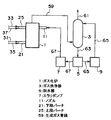
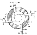
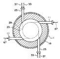
以下、本発明を適用してなるガス化装置の第1の実施形態について図1乃至図4を参照して説明する。図1は、本発明を適用してなるガス化装置の概略構成と動作を示すブロック図である。図2は、本発明を適用してなるガス化装置が備えるガス化炉の概略構成と動作を示す縦断面図である。図3は、本発明を適用してなるガス化装置が備えるガス化炉の概略構成と動作を示す下段バーナが設けられた段部の横断面図である。図4は、本発明を適用してなるガス化装置が備えるガス化炉の概略構成と動作を示す上段バーナが設けられた段部の横断面図である。なお、本実施形態では、ガス化炉内に上昇する旋回流を形成する上段バーナと下降する旋回流を形成する上段バーナとの2段に配置されたバーナを有する旋回流式のガス化炉を備えたガス化装置を例示している。
【0024】
本実施形態のガス化装置は、図1に示すように、固体燃料として粒体状または粉体状の固体炭化水素、例えば微粉砕した石炭を燃料としてガス化を行うガス化炉1、ガス化炉1で生成された生成ガス中の未反応の可燃成分である炭素分を含む煤塵つまりチャーなどを水またはアルカリ溶液などによって洗浄し生成ガス中から除去するガス洗浄器3、ガス洗浄器3からのチャーを含む洗浄排水中の水の一部を分離するための脱水機5、脱水機5で水の量が調整されることで生成されたスラリを加圧して搬送するためのスラリポンプ7、脱水機5で分離された水をガス洗浄器3に戻すための洗浄水ポンプ9、そして、スラリポンプ7で搬送されたスラリをガス化炉1内に供給するためのノズル11などで構成されている。
【0025】
ガス化炉1は、図1及び図2に示すように、縦型の炉であり、ガス化室13、ガス化室13の下方に設けられたスラグ回収室15などを有している。また、ガス化炉1のガス化室13の上方には、ガス化炉1で生成された生成ガスを冷却するための冷却器17が連結されている。ガス化室13は、円筒形に形成されており、内面に耐火材19が内張りされる。ガス化炉1のガス化室13の下側部分には、下段バーナ21が、下段バーナ21よりも上側で、かつガス化室13からの生成ガスの出口23側の部分には上段バーナ25が、そして、ガス化炉1のガス化室13の上段バーナ25が設けられた段部にノズル11が設けられている。
【0026】
下段バーナ21は、図3に示すように、下段バーナ21からの燃料などの噴出方向を、旋回流を形成する位置に仮定されるガス化炉1の外壁との同心円27の接線方向に沿わせた状態で設置される。このように下段バーナ21が設けられることにより、ガス化炉1のガス化室13内に同心円27に沿う旋回流が形成される。なお、本実施形態では、4本の下段バーナ21が等間隔で設置されている。上段バーナ25は、図4に示すように、上段バーナ25からの燃料などの噴出方向を、旋回流を形成する位置に仮定されるガス化炉1の外壁との同心円29の接線方向に沿わせた状態で設置される。このように上段バーナ25が設けられることにより、ガス化炉1のガス化室13内に同心円29に沿う旋回流が形成される。なお、本実施形態では、2本の上段バーナ25が等間隔に設置されている。
【0027】
本実施形態では、ノズル11も、上段バーナ25と同様に、旋回流を形成する位置に仮定されるガス化炉1の外壁との同心円29の接線方向に沿わせた状態で設置されている。本実施形態では、2本のノズル11がガス化炉1の上段バーナ25が設置された段部に上段バーナ25と交互に等間隔で設置されている。なお、ノズル11は、ノズル11からガス化炉1内に供給されたスラリが上段バーナ25によって形成された旋回流に同伴されればよいため、ガス化炉1の上段バーナ25が設置された段部であれば、上段バーナ25の設置位置と同じ高さに設ける必要はなく、上段バーナ25の設置位置よりも高い位置や低い位置にも設けることができる。
【0028】
さらに、ガス化炉1の上段バーナ25が本実施形態のような2段のバーナを有するガス化炉1では、ノズル11からガス化炉1内に供給されたスラリは、上段バーナ25が形成する下降する旋回流つまり下降流に同伴されて、出口23に向かうガス化炉1内の生成ガスの流れである上昇流に対向する方向に流れる。したがって、ノズル11は、本実施形態のように同心円29に沿う旋回流を形成する状態で設置する必要はない。ただし、本実施形態のように同心円29に沿う旋回流を形成する状態でノズル11を設置すれば、上段バーナ25が形成する下降する旋回流を乱し難いので好ましい。
【0029】
予め微粉砕された石炭は、図1及び図2に示すように、下段バーナ21に連結され、固体燃料の流路となる下段側燃料管路31と、上段バーナ25に連結され、固体燃料の流路となる上段側燃料管路33とに分割され、窒素や二酸化炭素などの不燃性ガスにより下段バーナ21と上段バーナ25を介してガス化炉1内に供給される。さらに、下段バーナ21と上段バーナ25には、ガス化剤となる酸素を下段バーナ21と上段バーナ25に導くための酸素または空気の流路となる下段側酸素管路35と上段側酸素管路37とが各々連結されており、酸素または空気は、下段バーナ21と上段バーナ25を介して微粉砕された石炭と共にガス化炉1内に供給される。
【0030】
ガス化室13とスラグ回収室15とは、図2に示すように、ガス化室13及びスラグ回収室15の内径よりも径が細く形成されたスラグタップ39を介して接続される。スラグ回収室15には、点火バーナ41及びスラグタップバーナ43が設置されている。点火バーナ41には、補助燃料を点火バーナ41に導くための流路となる補助燃料管路45と、酸素または空気を点火バーナ41に導くための流路となる点火バーナ用酸素管路47とが連結されている。スラグタップバーナ43にも、点火バーナ41と同様に、補助燃料をスラグタップバーナ43に導くための流路となる補助燃料管路49と、酸素または空気をスラグタップバーナ43に導くための流路となるスラグタップバーナ用酸素管路51とが連結されている。なお、スラグタップバーナ43は、必ず設ける必要はない。
【0031】
ガス化炉1の上方には、図2に示すように、ガス化炉1の生成ガスの出口23に連通し、上下方向に延在する生成ガスの流路からなる冷却室53を有する冷却器17が設けられている。冷却室53を画成する側壁は、水などの冷却液や冷却用蒸気などの冷却媒体が通流する管路で形成された水冷壁式または冷却媒体が通流する流路54が内部に形成されたジャケット式の熱交換器となっており、冷却器17の下部には、冷却媒体を冷却器17に導入する冷却媒体導入管路55が、冷却器17の上部には、熱交換して加熱された冷却媒体を冷却器17から導出する冷却媒体導出管路57が連結されている。なお、図1では冷却器17の図示を省略しているが、冷却器17は、ガス化炉1から排出される生成ガスの温度に応じて設置すべきか否かが決定されるものであり、本発明のガス化装置においては、必ず必要なものではない。
【0032】
ガス化炉1のガス化室13で生成された生成ガスは、冷却器17が設けられていない場合には、ガス化炉1のガス化室13の出口23に、冷却器17が設けられていない場合には、冷却器17の上端部に連結され、生成ガスの流路となる生成ガス管路59に流入する。生成ガス管路59に流入した生成ガスは、図1に示すように、生成ガス管路59内を通流し、生成ガス管路59が連結されたガス洗浄器3に導かれる。
【0033】
ガス洗浄器3で洗浄された生成ガスである精製ガスは、ガス洗浄器3に連結され、精製ガスの流路となる精製ガス管路61を介して、ガス化装置の後段に配された設備や機器類などに導かれる。一方、生成ガスに同伴されていたチャーなどの煤塵を含むガス洗浄器3からの洗浄排水は、洗浄排水の流路となる洗浄排水管路63を介して、脱水機5に導かれる。なお、精製ガス管路61には、精製ガス管路61内を通流する精製ガスの温度やガス化装置の後段に配された設備や機器類などが要求する精製ガスの温度などに応じて、冷却器17とは別に、精製ガスを冷却する冷却器が設けられる場合がある。この精製ガス管路61に設けられる冷却器としては、一般に、精製ガスが通流する流路内に冷却媒体が通流する複数の管路が設置された構造のものが用いられる。脱水機5は、洗浄排水管路63を介してガス洗浄器3から導かれてきた洗浄排水から余分な水を分離することにより、チャーを含むスラリを生成する。脱水機5としては、洗浄排水から余分な水を分離することができれば、ストレーナ、フィルタ、沈降層、遠心分離など様々な方式の脱水機が使用できる。このようにガス洗浄器3と脱水機5はスラリ生成手段を構成している。
【0034】
脱水機5で分離された水は、洗浄水ポンプ9が設けられた洗浄水管路65を介してガス洗浄器3に再供給され、洗浄水として使用される。一方、脱水機5で生成されたスラリは、スラリポンプ7を設けたスラリ供給管路67を介してガス化炉1に設けられたノズル11に搬送される。スラリポンプ7は、スラリをガス化炉1の運転圧力以上に加圧してノズル11に搬送する。
【0035】
このような構成のガス化装置の動作と本発明の特徴部について説明する。ガス化炉1内の下段バーナ21が設けられた段部では、固体燃料中の可燃成分の一部がガス化剤により酸化されること、つまり固体燃料中の可燃成分が部分燃焼することにより、例えば1500℃程度の高熱を発する。このガス化室13内の高熱により、固体燃料中の灰分は溶融し、スラグタツプ39を通じてスラグ回収室15に回収される。
【0036】
一方、固体燃料中の可燃成分の残りは、ガス化室13内で水素や一酸化炭素といった可燃性のガスに変換される。ガス化室13内で生成された可燃性のガスである生成ガスは、ガス化炉1の出口23から生成ガス管路59に排出される。生成ガス管路59を通流するガス化炉1からの生成ガスに同伴されている未反応の可燃成分である炭素分を含む煤塵は、ガス洗浄器3で洗浄水によって回収される。ガス洗浄器3からの回収された煤塵を含む洗浄排水は、脱水機5で、予め設定された量の水が分離されることで所望の濃度でスラリ化される。
【0037】
得られたスラリは、スラリポンプ7でガス化炉1の運転圧力以上に加圧されてノズル11からガス化炉1内に供給される。ガス化炉1内に供給されたスラリは、上段バーナ25で形成された、ガス化炉1の出口23に向かうガス化炉1内の生成ガスの流れに対向する方向の流れである下降流に同伴されてガス化炉1内の下段バーナ21が設けられた段部に流れる。スラリとしてガス化炉1内に再供給された未反応の可燃成分は、ノズル11から下段バーナ21が設けられた段部に下降し、さらに下段バーナ21が設けられた段部から上段バーナ25が設けられた段部に上昇する間、再度反応の機会に曝されガス化される。さらに、水を含むスラリがノズル11によって上段バーナ25が設けられた段部に供給されるため、ガス化炉1内の熱でスラリ中の水分が蒸発することによってガス化炉1の上段バーナ25が設けられた段部が冷却され、ガス化炉1から排出される生成ガスの温度が低下する。
【0038】
ここで、2段のバーナを備えた旋回炉式のガス化炉を備えたガス化装置において、スラリを下段バーナが設けられた段部に供給する従来のガス化装置と、本実施形態のガス化装置との生成ガスのガス化炉からの出口温度と燃料のガスへの変換効率を比較した結果を表1に示す。なお、変換効率とは、原料の発熱量が生成ガスの発熱量に変換した割合を示す。すなわち、
(変換効率)=(生成ガスの発熱量)/(燃料の発熱量)×100
である。
【0039】
【表1】

【0040】
これに対して、本実施形態のガス化装置では、酸素/石炭重量比が1.0で、ガス化炉温度を1500℃程度とすることができ灰分を溶融することができた。さらに、生成ガスのガス化炉からの出口温度は900℃程度まで冷却でき、ガス化炉の出口部への灰の付着を抑制できた。また、変換効率は60%となり、変換効率の低下はなかった。
【0041】
このように本実施形態のガス化装置では、スラリがガス化炉1の上段バーナ25が設けられた段部、つまりガス化炉1の生成ガスの出口23側に供給されることにより、ガス化炉1の上段バーナ25が設けられた段部の熱でスラリ中の水分が蒸発することにより、ガス化炉1の上段バーナ25が設けられた段部が冷却され、ガス化炉1から排出される生成ガスの温度を低下できる。さらに、ノズル11からガス化炉1内に供給されたスラリが、出口23に向かうガス化炉1内の生成ガスの流れに対向する方向に流れることにより、スラリに含まれる未反応の可燃成分がガス化炉1内に留まる時間を長くでき、スラリに含まれる未反応の可燃成分の反応量を増加できる。したがって、燃料のガスへの変換効率を向上しながらガス化炉から排出される生成ガスの温度を低下できる。
【0042】
さらに、本実施形態のガス化装置では、ガス化炉から排出される生成ガスの温度を低下できることにより、必要とされる冷却能力を低くできるため、図2に示す冷却器17のようなガス化炉の出口に連続させて設けた冷却器を小型化できる。また、ガス化炉から排出される生成ガスの温度が、スラグが生成される可能性のある温度以下であれば、図2に示すような冷却器17を、冷却器17よりも冷却効率の高いガスが通流する流路内に冷却媒体が通流する複数の管路が設置された構造の冷却器に代えることで、さらに冷却器を小型化することもできる。加えて、スラリの供給によって冷却された生成ガスの温度にもよるが、図2に示す冷却器17のようなガス化炉の出口に連続させて設けた冷却器を無くすこともできる。また、ガス化炉の出口に連続させて設けた冷却器を小型化または無くすことができることにより、ガス化装置の小型化やコストの低減ができる。
【0043】
特に、本実施形態のような2段のバーナを有する旋回流式のガス化炉は、他の気流層方式のガス化炉に比べて高効率でガス化ができ、また、同処理量で比較するとより小さな炉容積にできることが特徴である反面、熱負荷が高くなるため、ガス化炉から排出される生成ガスの温度が他の気流層方式のガス化炉に比べて高い。このため、本実施形態のような旋回流式のガス化炉を備えたガス化装置では、他の気流層方式のガス化炉に比べて、冷却器17のようなガス化炉の出口に連続させて設けた冷却器が大型化してしまい、ガス化装置の大型化やコストの増大が生じる場合が多い。したがって、本実施形態のような2段のバーナを有する旋回流式のガス化炉を備えたガス化装置に本発明を適用することは、ガス化装置の小型化やコストの低減といった効果が他の気流層方式のガス化炉を備えたガス化装置に比べて大きい。ただし、本発明は、旋回流式のガス化炉を備えたガス化装置に限らず、その他の2段のバーナを有するガス化炉や1段のバーナのみを有するガス化炉を備えたガス化装置など、様々な気流層方式のガス化炉を備えたガス化装置に適用できる。
【0044】
さらに、本実施形態では、スラリ生成手段として洗浄水によって生成ガス中の煤塵を回収するガス洗浄器3と脱水機5を用いるため、煤塵を含むスラリを生成する際に、乾燥した状態で回収した煤塵に水を添加するための機器類を設ける必要がない。ただし、サイクロンなどを用いて生成ガスから乾燥状態で煤塵を回収し、これに水を加えてスラリを生成する構成にすることもできる。
【0045】
また、本実施形態のガス化装置では、煤塵をスラリとしてポンプで加圧してガス化炉に再供給するため、ロックホッパを使用して乾燥状態の煤塵をガス化炉に再供給するものに比べ、煤塵搬送用の窒素ガスなどが不要となり、窒素ガスなどの生成ガスとして得たい目的とするガス以外のガスの生成ガス中の濃度を低減し、目的とするガスの生成ガス中の濃度を高くできる。例えば、固体燃料として炭化水素を用い水素ガスを得たい場合、水素ガスの生成ガス中の濃度を高くできる。また、ロックホッパを使用しないため、ロックホッパにかかわるコストを削減することができる。さらに、表1に示すように、固体燃料の生成ガスへの変換効率を向上できる。
【0046】
また、本実施形態では、4本の下段バーナ21、2本の上段バーナ25、そして2本のノズル11を備えた構成としているが、下段バーナ21と上段バーナ25は旋回流を形成できればよく、下段バーナと上段バーナの本数は適宜選択でき、また、本実施形態のノズル11は、スラリをガス化炉1内に供給することを目的とするものであるため、ノズルの流量などに応じて本数は適宜選択できる。ただし、ノズル11は、上段バーナ25が形成する下降する旋回流を乱し難い本数及び配置で設置することが望ましい。
【0047】
(第2の実施形態)
以下、本発明を適用してなるガス化装置の第2の実施形態について図5を参照して説明する。図5は、本発明を適用してなるガス化装置の概略構成と動作を示すブロック図である。なお、本実施形態では、第1の実施形態と同一のもの及び動作などには同じ符号を付して説明を省略し、第1の実施形態と相違する構成及び特徴部などについて説明する。
【0048】
本実施形態のガス化装置が第1の実施形態と相違する点は、ガス化炉から排出される生成ガスの温度を検出し、この温度に応じてスラリ中の水の量を調整することにある。すなわち、本実施形態のガス化装置は、図5に示すように、生成ガス管路59のガス化炉1の出口に連結された部分に、生成ガス管路59内を通流する生成ガスの温度を検出する温度計69、脱水機5の動作を制御する制御部71などを有している。温度計69と制御部71、そして制御部71と脱水機5は、各々配線73を介して電気的に接続されている。
【0049】
ここで、スラリの供給により冷却されてガス化炉から排出される生成ガスの温度は、スラリ中の煤塵と水との比によって決まる。そこで、本実施形態のガス化装置では、温度計69が、ガス化炉1から排出される生成ガスの温度を計測して、その計測値に対応する温度信号を制御部71に発信する。温度計69からの温度信号を受信した制御部71は、温度計69で計測したガス化炉1から排出される生成ガスの温度と、予め設定した温度または温度範囲とから、ノズル11からガス化炉1内に供給するスラリ中の水分濃度を演算し、脱水機5の動作を制御して、脱水機5で分離する水分量を調節する。そして、水分量が調整されたスラリがノズル11からガス化炉1内に供給されることにより、ガス化炉1内の上段バーナ25に対応する段部を冷却し、ガス化炉1から排出される生成ガスの温度を制御し、一定に保っている。
【0050】
このように本実施形態のガス化装置では、ガス化炉1から排出される生成ガスの温度に応じて水分量を調整したスラリをガス化炉1の出口側に供給することにより、ガス化炉から排出される生成ガスの温度を制御できる。
【0051】
ところで、前述のように、スラリの供給により冷却されてガス化炉から排出される生成ガスの温度は、スラリ中の煤塵と水との比によって決まるため、生成ガスに同伴される煤塵の量が変動するとガス化炉から排出される生成ガスの温度が変動することになる。このため、生成ガスに同伴される煤塵の量の変動が許容範囲にある場合には、第1の実施形態のように、煤塵を含む洗浄水から常に一定量の水を分離する構成でよいが、生成ガスに同伴される煤塵の量の変動が許容範囲を越える場合などには、本実施形態の構成のガス化装置を用いることが望ましい。
【0052】
(参考例)
以下、本発明を適用してなるガス化装置の参考例について図6を参照して説明する。図6は、本発明を適用してなるガス化装置の概略構成と動作を示すブロック図である。なお、本参考例では、第1及び第2の実施形態と同一のもの及び動作などには同じ符号を付して説明を省略し、第1及び第2の実施形態と相違する構成及び特徴部などについて説明する。
【0053】
本参考例のガス化装置が、第1及び第2の実施形態と相違する点は、ガス化炉の炉頂部に固体燃料とガス化剤を供給するバーナを備え、ガス化炉内で生成された生成ガスがガス化炉内を上方から下方に向かって流れ、生成ガスの出口がガス化炉の下部に設けられた下降流方式のガス化炉を備えていることにある。すなわち、本参考例のガス化装置は、下降流方式のガス化炉75を備えており、生成ガス管路59がガス化炉75の下部に位置する出口に連結され、ガス化炉75の炉頂部にバーナ79が、ガス化炉75の下部側つまり出口側の部分にノズル11が設置されている。
【0054】
固体燃料である予め微粉砕された石炭などは、バーナ79に連結され、燃料の流路となる燃料供給管路81及びバーナ79を介してガス化炉75に供給される。同時に、ガス化剤となる酸素が、バーナ79に連結され、酸素または空気の流路となる酸素供給管路83及びバーナ79を介してガス化炉75に供給される。ガス化炉75内では、固体燃料中の可燃成分の一部がガス化剤により酸化されることにより、例えば約1500℃といった高熱を発するとともに、上記可燃成分の残りは、水素や一酸化炭素といった可燃性のガスに変換される。発生した生成ガスは、ガス化炉75の下部に位置する出口に連結された生成ガス管路59に取り出される。
【0055】
ガス洗浄器3からの洗浄排水を脱水機5で処理することにより生成された可燃成分を含む煤塵で形成されたスラリは、スラリポンプ7を用いて、ガス化炉75の運転圧力以上に加圧され、ノズル11を介してガス化炉75の下部に供給される。本参考例のノズル11は、ガス化炉75内の上方に向けてスラリを噴出する状態で設置されており、ノズル11から噴出されたスラリは、ガス化炉75内の生成ガスの上方に向けて噴流される。したがって、ノズル11からガス化炉75内に供給されたスラリは、ガス化炉75内の出口に向かう生成ガスの流れに対向する方向に流れる。これにより、ノズル11からガス化炉75内に供給されたスラリは、ガス化炉75内の高温に曝される時間が長くなり、スラリ中の未反応の可燃成分が反応し、一酸化炭素などの可燃性ガスを発生する。さらに、ノズル11からガス化炉75内に供給されたスラリの水分は、ガス化炉75に供給後、直ちに蒸発し、ガス化炉75の下部を冷却してガス化炉75から排出される生成ガスの温度を低下させる。
【0056】
このように本参考例でも、燃料のガスへの変換効率を向上しながらガス化炉から排出される生成ガスの温度を低下できる。したがって、本発明は、第1及び第2の実施形態のような2段のバーナを備えた旋回流式のガス化炉や下方から上方に生成ガスが流れるガス化炉などを備えたガス化装置に限らず、ノズルから噴出されるスラリでガス化炉内のガス化炉の出口に向かう生成ガスの流れに対向する方向へのスラリの流れを形成することで、2段のバーナを備えた旋回流式のガス化炉や下方から上方に生成ガスが流れるガス化炉を備えたガス化装置以外の様々な気流層方式のガス化炉を備えたガス化装置に適用することができる。
【0057】
(第3の実施形態)
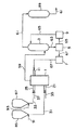
本実施形態では、本発明を適用してなるガス化装置を備えた水素製造装置の一実施形態について図7を参照して説明する。図7は、本発明を適用してなるガス化装置を備えた水素製造装置の概略構成と動作を示すブロック図である。なお、本実施形態では、第1、第2の実施形態及び参考例と同一のもの及び動作などには同じ符号を付して説明を省略し、第1、第2の実施形態及び参考例と相違する構成及び特徴部などについて説明する。
【0058】
本実施形態は、第1の実施形態のガス化装置を用いて水素製造装置を形成したものである。本実施形態の水素製造装置は、粒体状または粉体状の固体炭化水素、例えば微粉砕した石炭よりなる原料から水素ガスを製造するものであり、図6に示すように、第1の実施形態のガス化装置と同様の構成のガス化炉1、ガス洗浄器3、脱水機5、スラリポンプ7、洗浄水ポンプ9、そしてガス化炉1に設けられたノズル11に加え、下段バーナ21に下段側燃料管路31を介して連結された下段原料ホッパ85、上段バーナ25に上段側燃料管路33を介して連結された上段原料ホッパ87、精製ガス管路61に設けられて触媒が収容されたシフト反応器89などで構成されている。
【0059】
水素製造の原料である予め微粉砕された石炭は、下段原料ホッパ85用と上段原料ホッパ87用に分割され、下段原料ホッパ85と上段原料ホッパ87に収容される。下段原料ホッパ85に収容された原料及び上段原料ホッパ87に収容された原料は、それぞれ下段原料ホッパ85及び上段原料ホッパ87から定量排出され、下段原料ホッパ85及び上段原料ホッパ87の原料の搬出部に各々連結された下段原料搬送用窒素管路91及び上段原料搬送用窒素管路93から供給される搬送用窒素と混合されて気流搬送される。原料及び搬送用窒素は、下段側燃料管路31を介して下段バーナ21に、上段側燃料管路33を介して上段バーナ25に各々供給され、下段バーナ21及び上段バーナ25からガス化炉1内に供給される。このとき、下段バーナ21と上段バーナ25とには、各々下段側酸素管路35と上段側酸素管路37とによって酸素または空気が供給されるため、下段バーナ21及び上段バーナ25は、各々原料と共にガス化剤である酸素または空気をガス化炉1内に供給する。
【0060】
ガス化炉1内では、原料と酸素が混合され、原料中の可燃成分の一部が酸化されて高熱を発する。また、残りの可燃成分は水素や一酸化炭素を主成分とするガスに変換され、生成ガスとしてガス化炉1から生成ガス管路59に取り出される。生成ガス管路59を通流する生成ガスは、ガス洗浄器3で洗浄水により同伴している煤塵を除去されるが、このとき、生成ガスは、100℃以上であり、洗浄水の一部はこの熱によって蒸発し、精製ガスに混入する。ガス洗浄器3で得られた蒸気を含む精製ガスは、精製ガス管路61に流入し、精製ガス管路61に設けられたシフト反応器89に導入される。シフト反応器89内には、式(1)のシフト反応を促進させる触媒作用をもつシフト反応触媒、例えば銅−亜鉛系の触媒や鉄−クロム系の触媒などの公知の触媒が収容されている。
CO+H2O→CO2+H2 …(1)
したがって、蒸気を含む精製ガスがシフト反応器89に流入してシフト反応触媒と接触することにより、式(1)のシフト反応を生じ、精製ガス中の水素濃度を高め、精製ガスは、製品ガスとなってシフト反応器89から取り出され、精製ガス管路61を介して製品ガスを利用する設備や機器類などに送られる。このように、シフト反応器89でのシフト反応に必要な水分は、ガス洗浄器3で蒸発して精製ガスに蒸気として混入した洗浄水の一部が使用される。
【0061】
一方、ガス洗浄器3で生成ガスから回収された煤塵は、洗浄水と混合されて洗浄排水として洗浄排水管路63に取り出される。洗浄排水管路63に取り出された洗浄排水は、脱水機5に導入され、一部の水が分離されてスラリ化される。脱水機5によって精製されたスラリは、スラリポンプ7によりガス化炉1の運転圧力以上に加圧されて、スラリ供給管路67を介してノズル11に搬送され、ノズル11からガス化炉1内に供給される。ガス化炉1内に供給されたスラリ中の未反応の炭素分は、ガス化炉1内で更に反応し、一酸化炭素などのガスに変換される。また、ガス化炉1内に供給されたスラリ中の水分は、ガス化炉1内の上段バーナ25が設けられている段部を冷却すると共に、式(1)のシフト反応に使用されて水素ガスに変換される。
【0062】
このように本実施形態の水素製造装置では、精製ガスに同伴された煤塵をスラリとしてガス化炉内の出口側に再供給することで、ガス化炉にスラリとして供給される適度な量の水分により、一酸化炭素を水素に変換し、生成ガス中の水素濃度を増大できる。さらに、ガス化炉の出口に連続させて設けた冷却器を小型化できるかまたは無くすことができることにより、水素製造装置を小型化できる。
【0063】
また、本実施形態の水素製造装置では、ガス洗浄器3で洗浄水によって生成ガスを洗浄することで洗浄水の一部が蒸発し、蒸発した洗浄水がガス洗浄器3からの精製ガスに同伴する。この蒸気を同伴した精製ガスを、シフト反応触媒を収容したシフト反応器89に導入することにより、精製ガス中に残った一酸化炭素を水素に変換することができる。このため、製品ガス中の水素濃度を一層増大することができる。さらに、これらのシフト反応に必要な水蒸気は、洗浄水の再供給と洗浄水の蒸発により賄うことができるため、水分を補うために別途ボイラなどを設ける必要がない。加えて、ガス洗浄器3により生成ガスを冷却するが、このとき、生成ガスの熱は、シフト反応器89での反応に利用される水蒸気の発生、つまり洗浄水と直接接触して洗浄水の蒸発に使用される。したがって、別途ボイラなどを設け、生成ガスの熱でこのボイラによって水蒸気を発生させる場合と比較して熱効率の低下が少ないか、またはない。
【0064】
また、本発明は、第1乃至第2の実施形態の構成のガス化装置、及び第3の実施形態の水素製造装置に限らず、気流層方式のガス化炉を備えた様々な構成のガス化装置や水素製造装置に適用することができる。
【0065】
【発明の効果】
本発明によれば、燃料のガスへの変換効率を向上しながらガス化炉から排出される生成ガスの温度を低下できる。
【図面の簡単な説明】
【図1】本発明を適用してなるガス化装置の第1の実施形態の概略構成と動作を示すブロック図である。
【図2】第1の実施形態のガス化装置が備えるガス化炉の概略構成と動作を示す縦断面図である。
【図3】第1の実施形態のガス化装置が備えるガス化炉の概略構成と動作を示す下段バーナが設けられた段部の横断面図である。
【図4】第1の実施形態のガス化装置が備えるガス化炉の概略構成と動作を示す上段バーナが設けられた段部の横断面図である。
【図5】本発明を適用してなるガス化装置の第2の実施形態の概略構成と動作を示すブロック図である。
【図6】本発明を適用してなるガス化装置の参考例の概略構成と動作を示すブロック図である。
【図7】本発明を適用してなるガス化装置を備えた水素製造装置の一実施形態の概略構成と動作を示すブロック図である。
【符号の説明】
1 ガス化炉
3 ガス洗浄器
5 脱水機
7 スラリポンプ
11 ノズル
21 下段バーナ
25 上段バーナ
59 生成ガス管路[0001]
BACKGROUND OF THE INVENTION
The present invention relates to a solid fuel gasification technique, and more particularly to a solid fuel gasification technique using a gas-flow-type gasification furnace.
[0002]
[Prior art]
Gasifiers that pulverize solid fuels, such as solid hydrocarbons such as coal, and partially burn with oxygen to generate gas, what are called fixed beds, fluidized beds, and gas flow layers or spouted beds Various methods have been proposed. Among these, the method called the airflow layer or the spouted layer can operate the gasification furnace at a relatively high temperature such as 1500 ° C., and the conversion efficiency of the fuel into the gas is different from that of other methods. Higher than that. Moreover, since the operation of the gasification furnace at a relatively high temperature is possible, the ash content in the solid fuel such as hydrocarbon can be melted, so that the ash content can be recovered and reused as slag. Such gas-flow type gasification furnaces have been proposed in Japanese Patent Publication No. 5-25919, Japanese Patent Application Laid-Open No. 59-84980, and the like.
[0003]
Here, in a gasification apparatus equipped with such a gas-flow-layer-type gasification furnace, the generated gas generated in the gasification furnace and discharged from the gasification furnace is an unreacted combustible component such as an unreacted char. It is accompanied by dust containing carbon such as tar and tar. For this reason, a gasifier having a configuration that improves the conversion efficiency of fuel to gas by re-supplying the unreacted combustible component accompanying the generated gas to the gasification furnace and utilizing the combustible component as much as possible. JP-A-58-138790, JP-A-60-260689, JP-A-61-292, JP-A-62-131094, JP-A-2719424, JP-A-7-278575, This is proposed in Japanese Unexamined Patent Publication No. 2000-328074.
[0004]
In the gasifier as proposed in Japanese Patent Laid-Open Nos. 58-138790 and 7-278575, the gasifier is formed on one end side of the gasifier formed in a cylindrical shape. A gasification furnace having a structure in which a gas outlet is provided and a burner for supplying fuel, oxygen, or air is provided on the other end side. Then, the soot containing unreacted combustible components entrained by the product gas discharged from the gasification furnace outlet is recovered from the product gas, and the recovered soot and solid fuel such as finely pulverized coal are collected. Mix to make a slurry. Then, the slurry is pressurized as a fuel with a pump or the like above the operating pressure of the gasifier and supplied to the gasifier. In such a gasifier, since the solid fuel finely pulverized together with the dust collected from the generated gas is supplied to the gasifier as a slurry, the amount of heat generated in the fuel is reduced by the moisture supplied into the gasifier. .
[0005]
On the other hand, in a gasifier such as that proposed in Japanese Patent Laid-Open No. 2000-328074, finely pulverized powder or granular solid fuel is contained in the gasifier by a gas for transporting the solid fuel. The air is conveyed to On the other hand, soot that entrains finely pulverized fuel with the product gas is removed and recovered from the product gas by a cyclone and a filter, etc., and this recovered dry soot is operated in the gasifier through the lock hopper. Pressurized above the pressure and re-supplied to the gasifier. Therefore, in the supply of fuel and the re-supply of dust collected from the generated gas, moisture is not supplied into the gasification furnace, so that a decrease in the heat generation amount of the fuel can be suppressed. However, in such a gasification apparatus, a lock hopper is required to re-supply the dust collected from the generated gas to the gasification furnace, which increases the cost of the apparatus.
[0006]
On the other hand, in the gasifier as proposed in JP-A-60-260689, JP-A-61-292, JP-A-62-131094, Japanese Patent No. 2719424, etc., As a gasification furnace, a product gas outlet is provided on one end side of a gasification furnace formed in a cylindrical shape, and a burner for supplying fuel, oxygen, or air is provided on the other end side. A gasification furnace is provided, and the solid fuel is supplied to the gasification furnace via a burner by airflow conveyance. On the other hand, the dust accompanying the generated gas discharged from the gasification furnace is recovered from the generated gas and slurried, and the slurry containing this dust is pressurized to a pressure higher than the operating pressure of the gasification furnace by a pump or the like, The gasification furnace is re-supplied to the step provided with the burner. With such a gasifier, since the solid fuel is supplied to the gasifier by airflow conveyance, it is possible to reduce a decrease in the heat generation amount of the fuel, that is, a decrease in the temperature in the gasifier.
[0007]
Further, Japanese Patent Publication No. 57-17914 discloses a slurry produced by collecting soot and dust containing char and tar accompanying the produced gas in a gasifier equipped with a fluidized bed type gasifier. It is described that it is resupplied to the char combustion zone at the bottom of the furnace.
[0008]
[Problems to be solved by the invention]
By the way, in the conventional gasifier, in order to cool the temperature of the generated gas generated in the gasifier to the temperature required by the equipment and equipment to which the generated gas is sent, the generated gas continuous at the outlet of the gasifier A cooler having a flow path is provided to cool the product gas discharged from the gasification furnace. For example, when the product gas is processed with a desulfurization apparatus or the like, the desulfurization process is generally performed at room temperature, and thus it is necessary to cool the product gas so that it can be brought to room temperature with the desulfurization apparatus. As such a cooler for cooling the product gas, a boiler type cooler that cools the product gas by exchanging heat between the product gas and a fluid such as water or steam flowing through the flow path is used. It has been.
[0009]
At this time, depending on the temperature of the product gas discharged from the gasification furnace, slag may be generated by melting of ash accompanying the product gas discharged from the gasification furnace. For this reason, if a cooler having a structure in which a plurality of pipes through which fluid that exchanges heat with the product gas flows is used as a cooler, a gap between the pipes through which the fluid flows, etc. In some cases, slag adheres to the flow path of the product gas. Therefore, in the gasification apparatus in which the temperature of the product gas discharged from the gasification furnace may become a temperature at which slag is generated, the flow path of the product gas is used to prevent the flow path from being blocked by the slag. A cooler having a flow path through which a fluid that exchanges heat with the product gas flows is connected to the outlet of the gasification furnace.
[0010]
Coolers such as water-cooled wall structures and jacket structures are large in size because the heat exchange efficiency, that is, the cooling efficiency, is lower than the cooler having a structure in which a plurality of pipes are arranged in the flow path of the product gas. It will become. For example, it may be necessary to install a cooler with a height of several tens of meters for a gasification furnace with a height of several meters. A cooler such as a water-cooled wall structure or a jacket structure provided in such a gasifier causes an increase in the size and cost of the gasifier. For this reason, it is desired to reduce the size of a cooler such as a water-cooled wall structure or a jacket structure by lowering the temperature of the product gas discharged from the gasification furnace.
[0011]
In contrast, the inventors of the present application supply slurry generated from the dust collected from the generated gas discharged from the gasifier to the outlet side of the generated gas of the gasifier, and the generated gas of the gasifier It is considered that the temperature of the product gas discharged from the gasification furnace is lowered by evaporation of water in the slurry supplied to the outlet side. However, if the slurry is supplied to the outlet side of the product gas of the gasification furnace, the supplied slurry is accompanied by the product gas and discharged from the gasification furnace. For this reason, the residence time of the unreacted combustible component contained in the slurry in the gasification furnace is shorter than that of the conventional gasifier that re-feeds the slurry containing soot and dust to the gasification furnace, and this unreacted combustible component However, it becomes difficult to react in the gasification furnace, and the conversion efficiency of fuel into gas cannot be improved. Therefore, it is necessary to reduce the temperature of the product gas discharged from the gasification furnace while improving the conversion efficiency of fuel into gas.
[0012]
An object of the present invention is to reduce the temperature of product gas discharged from a gasifier while improving the conversion efficiency of fuel into gas.
[0013]
[Means for Solving the Problems]
In the gasification method of the present invention, unreacted combustible components entrained by the product gas discharged from the outlet are formed in a portion of the gasification furnace outlet side of the gasification furnace that generates gas by partially burning solid fuel. The slurry generated by collecting the soot and dust is supplied, and the supplied slurry is used to flow the generated gas toward the outlet in the gasification furnace. Upflow The above-mentioned problem is solved by flowing in a direction opposite to.
[0014]
By setting it as such a structure, the temperature of the product gas discharged | emitted from a gasification furnace with the water | moisture content in a slurry can be lowered | hung by supplying slurry to the exit side part of the product gas of a gasification furnace. Furthermore, the unreacted combustible component contained in the slurry remains in the gasification furnace by flowing the slurry supplied into the gasification furnace in a direction opposite to the flow of the generated gas in the gasification furnace toward the outlet. The time can be lengthened and the reaction amount of unreacted combustible components contained in the slurry can be increased. Therefore, the temperature of the product gas discharged from the gasification furnace can be lowered while improving the conversion efficiency of fuel into gas.
[0015]
Further, a gasification furnace is provided in a lower burner for supplying the solid fuel into the gasification furnace and a portion on the outlet side from the lower burner of the gasification furnace, and supplies the solid fuel into the gasification furnace and gas. And an upper burner for forming a downward flow in the gasification furnace, and the slurry is supplied to a step portion provided with the upper gas burner. As a result, the slurry supplied to the outlet side portion of the gasifier is entrained by the downward flow formed by the upper burner, so the flow of the product gas toward the outlet in the gasifier Upflow It can be easily flowed in the direction opposite to.
[0016]
In addition, the flow of the product gas that spouts the slurry into the gasification furnace and goes to the outlet in the gasification furnace Upflow Forms a flow in the direction opposite to It is preferable to do. According to this, even if it does not form a downward flow by the upper stage burner, facing the upward flow that is the flow of the product gas in the gasifier, Product gas flow toward the outlet of the slurry Upflow It can be made to flow in the direction opposite to.
[0017]
Furthermore, the gasification apparatus of the present invention includes a gasification furnace that partially burns solid fuel to generate gas, a generation gas passage through which the generation gas generated in the gasification furnace flows, and the generation gas flow Recover the soot containing unreacted combustible components that are provided in the road and entrained with the generated gas, and generate slurry from the recovered soot, and pressurize the slurry generated by the slurry generating means A pump for transporting, and a nozzle for supplying the slurry transported from the slurry generating means by the pump into the gasification furnace, the nozzle being provided at a portion of the gasification furnace on the outlet side of the generated gas; The slurry supplied from the nozzle into the gasifier is the flow of the product gas in the gasifier toward the outlet. Upflow The above-mentioned problem is solved by adopting a configuration that flows in a direction opposite to.
[0018]
By setting it as such a structure, the temperature of the product gas discharged | emitted from a gasification furnace with the water | moisture content in slurry can be lowered | hung by supplying slurry to the exit side part of the product gas of a gasification furnace. Further, the slurry supplied from the nozzle into the gasification furnace flows in a direction opposite to the flow of the generated gas in the gasification furnace toward the outlet, so that unreacted combustible components contained in the slurry are contained in the gasification furnace. It is possible to increase the amount of time spent in the slurry, and to increase the amount of unreacted combustible components contained in the slurry. Therefore, the temperature of the product gas discharged from the gasification furnace can be lowered while improving the conversion efficiency of fuel into gas.
[0019]
Further, the gasification furnace is provided in a lower burner for supplying the solid fuel into the gasification furnace, and at a portion on the outlet side from the lower burner of the gasification furnace, and supplies the solid fuel into the gasification furnace and gas. And an upper burner that forms a downward flow in the gasification furnace, and the nozzle is provided in a step portion provided with the upper burner of the gasification furnace. In this way, if the nozzle is provided in the step portion where the upper burner of the two-stage burner type gasifier having the upper burner and the lower burner is provided, the slurry supplied from the nozzle into the gasifier is The flow of the product gas in the gasifier toward the outlet because it flows along with the downflow formed by To the upward flow that is It can easily flow in the opposite direction.
[0020]
The slurry generating means includes a cleaning device that cleans the generated gas flowing through the generated gas flow path with water or an alkaline solution and removes dust entrained in the generated gas from the generated gas and recovers the generated gas. A dehydrator that adjusts the amount of water in the slurry by removing a part of the water from the cleaning wastewater containing the collected dust is used. Such a configuration is preferable because it is not necessary to provide equipment for adding water to the dust when generating the slurry containing the dust.
[0021]
Furthermore, a temperature detector for measuring the temperature of the product gas discharged from the gasification furnace is provided, and the slurry generation means adjusts the amount of water contained in the slurry according to the temperature of the product gas detected by the temperature detector. The configuration. Such a configuration is preferable because the temperature of the product gas discharged from the gasification furnace can be controlled by the amount of water in the slurry.
[0022]
Moreover, it is set as the hydrogen production apparatus of the structure provided with one of the said gasifiers and a solid fuel is a solid hydrocarbon. The solid fuel further includes any one of the above gasifiers, and a catalyst reactor containing a catalyst for a reaction for generating hydrogen from carbon monoxide and water contained in the product gas discharged from the gasifier. Is a hydrogen production apparatus having a configuration in which is a solid hydrocarbon. With the hydrogen production apparatus having such a configuration, the hydrogen concentration in the product gas can be increased, and the hydrogen production apparatus can be downsized.
[0023]
DETAILED DESCRIPTION OF THE INVENTION
(First embodiment)
Hereinafter, a first embodiment of a gasifier to which the present invention is applied will be described with reference to FIGS. 1 to 4. FIG. 1 is a block diagram showing a schematic configuration and operation of a gasifier to which the present invention is applied. FIG. 2 is a longitudinal sectional view showing a schematic configuration and operation of a gasification furnace provided in a gasification apparatus to which the present invention is applied. FIG. 3 is a cross-sectional view of a step portion provided with a lower burner showing a schematic configuration and operation of a gasification furnace provided in a gasification apparatus to which the present invention is applied. FIG. 4 is a cross-sectional view of a step portion provided with an upper burner showing a schematic configuration and operation of a gasification furnace provided in a gasification apparatus to which the present invention is applied. In the present embodiment, a swirl flow type gasification furnace having a burner arranged in two stages of an upper burner that forms a swirling flow that rises in the gasification furnace and an upper burner that forms a swirling flow that descends is provided. The gasifier provided is illustrated.
[0024]
As shown in FIG. 1, the gasification apparatus of the present embodiment includes a gasification furnace 1 that performs gasification using granular or powdered solid hydrocarbons as solid fuel, such as finely pulverized coal, and gasification. From the
[0025]
As shown in FIGS. 1 and 2, the gasification furnace 1 is a vertical furnace, and includes a
[0026]
As shown in FIG. 3, the
[0027]
In the present embodiment, similarly to the
[0028]
Further, in the gasification furnace 1 in which the
[0029]
As shown in FIG. 1 and FIG. 2, the coal pulverized in advance is connected to the
[0030]
As shown in FIG. 2, the
[0031]
Above the gasification furnace 1, as shown in FIG. 2, a cooler having a cooling
[0032]
The produced gas produced in the
[0033]
The purified gas, which is the product gas cleaned by the
[0034]
The water separated by the
[0035]
The operation of the gasifier having such a configuration and the features of the present invention will be described. In the step portion provided with the
[0036]
On the other hand, the remainder of the combustible component in the solid fuel is converted into a combustible gas such as hydrogen or carbon monoxide in the
[0037]
The obtained slurry is pressurized to a pressure higher than the operating pressure of the gasifier 1 by the slurry pump 7 and supplied from the
[0038]
Here, in a gasifier having a swirl furnace type gasifier having two stages of burners, a conventional gasifier that supplies slurry to a stage provided with a lower stage burner, and the gas of the present embodiment Table 1 shows the result of comparison between the outlet temperature of the product gas from the gasification furnace and the conversion efficiency of the fuel into the gas. The conversion efficiency refers to the ratio of the heat value of the raw material converted into the heat value of the generated gas. That is,
(Conversion efficiency) = (calorific value of generated gas) / (calorific value of fuel) × 100
It is.
[0039]
[Table 1]
[0040]
In contrast, in the gasifier of this embodiment, the oxygen / coal weight ratio was 1.0, the gasifier temperature could be about 1500 ° C., and the ash content could be melted. Furthermore, the outlet temperature of the product gas from the gasification furnace could be cooled to about 900 ° C., and the adhesion of ash to the outlet part of the gasification furnace could be suppressed. Moreover, the conversion efficiency was 60%, and there was no decrease in the conversion efficiency.
[0041]
As described above, in the gasification apparatus according to the present embodiment, the slurry is supplied to the step portion where the
[0042]
Furthermore, in the gasification apparatus of the present embodiment, since the required cooling capacity can be lowered by reducing the temperature of the product gas discharged from the gasification furnace, the gasification like the cooler 17 shown in FIG. A cooler provided continuously at the outlet of the furnace can be reduced in size. If the temperature of the product gas discharged from the gasification furnace is equal to or lower than the temperature at which slag can be generated, the cooler 17 shown in FIG. 2 has a higher cooling efficiency than the cooler 17. The cooler can be further reduced in size by replacing with a cooler having a structure in which a plurality of pipes through which the cooling medium flows are installed in the flow path through which the gas flows. In addition, although depending on the temperature of the product gas cooled by the supply of the slurry, a cooler continuously provided at the outlet of the gasification furnace such as the cooler 17 shown in FIG. 2 can be eliminated. Further, since the cooler provided continuously at the outlet of the gasification furnace can be reduced in size or eliminated, the gasification apparatus can be reduced in size and cost can be reduced.
[0043]
In particular, a swirl type gasification furnace having a two-stage burner as in the present embodiment can be gasified with higher efficiency than other gas layer type gasification furnaces, and the same amount of treatment is compared. Then, although it is the feature that it can be made a smaller furnace volume, since the heat load becomes higher, the temperature of the generated gas discharged from the gasification furnace is higher than that of other gas-flow-layer type gasification furnaces. For this reason, in the gasification apparatus provided with the swirling flow type gasification furnace as in the present embodiment, it is continuously connected to the outlet of the gasification furnace such as the cooler 17 as compared with other gas stream type gasification furnaces. In many cases, the cooler provided is increased in size, resulting in an increase in size and cost of the gasifier. Therefore, applying the present invention to a gasifier having a swirl type gasification furnace having a two-stage burner as in this embodiment has other effects such as downsizing and cost reduction of the gasifier. It is larger than the gasifier equipped with the gasification furnace of the gas flow layer type. However, the present invention is not limited to a gasification apparatus including a swirling flow type gasification furnace, but is a gasification including another gasification furnace having a two-stage burner or a gasification furnace having only one-stage burner. The present invention can be applied to gasifiers equipped with various gas-flow-layer-type gasifiers, such as devices.
[0044]
Furthermore, in this embodiment, since the
[0045]
Further, in the gasification apparatus of the present embodiment, since dust is pressurized as a slurry with a pump and re-supplied to the gasification furnace, it is compared with a device that uses a lock hopper to re-supply dry dust to the gasification furnace. Nitrogen gas for dust transportation is not necessary, reducing the concentration of the target gas other than the target gas to be obtained as the generated gas, such as nitrogen gas, and increasing the concentration of the target gas in the generated gas it can. For example, when it is desired to obtain hydrogen gas using hydrocarbon as the solid fuel, the concentration of hydrogen gas in the generated gas can be increased. Moreover, since the lock hopper is not used, the cost related to the lock hopper can be reduced. Furthermore, as shown in Table 1, the conversion efficiency of the solid fuel into the product gas can be improved.
[0046]
In the present embodiment, four
[0047]
(Second Embodiment)
Hereinafter, a second embodiment of the gasifier to which the present invention is applied will be described with reference to FIG. FIG. 5 is a block diagram showing a schematic configuration and operation of a gasifier to which the present invention is applied. In the present embodiment, the same components and operations as those in the first embodiment are denoted by the same reference numerals, description thereof is omitted, and configurations and features that are different from those in the first embodiment will be described.
[0048]
The difference between the gasification apparatus of this embodiment and the first embodiment is that the temperature of the product gas discharged from the gasification furnace is detected and the amount of water in the slurry is adjusted according to this temperature. is there. That is, as shown in FIG. 5, the gasification apparatus according to the present embodiment is configured so that the generated gas flowing through the generated
[0049]
Here, the temperature of the product gas cooled by the supply of the slurry and discharged from the gasification furnace is determined by the ratio of dust and water in the slurry. Therefore, in the gasification apparatus of this embodiment, the
[0050]
As described above, in the gasification apparatus of the present embodiment, the gasification furnace is supplied with the slurry whose water content is adjusted according to the temperature of the product gas discharged from the gasification furnace 1 to the outlet side of the gasification furnace 1. It is possible to control the temperature of the product gas exhausted from the air.
[0051]
By the way, as described above, the temperature of the product gas cooled by the slurry supply and discharged from the gasifier is determined by the ratio of soot and water in the slurry, so the amount of soot accompanying the product gas is small. If it fluctuates, the temperature of the product gas discharged from the gasifier will fluctuate. For this reason, when the variation in the amount of dust accompanying the generated gas is within an allowable range, the configuration may be such that a certain amount of water is always separated from the cleaning water containing dust as in the first embodiment. When the variation in the amount of dust accompanying the generated gas exceeds the allowable range, it is desirable to use the gasifier having the configuration of this embodiment.
[0052]
( Reference example )
Hereinafter, a gasification apparatus to which the present invention is applied will be described. Reference example Will be described with reference to FIG. FIG. 6 is a block diagram showing a schematic configuration and operation of a gasifier to which the present invention is applied. Book Reference example The same components and operations as those in the first and second embodiments are denoted by the same reference numerals, and the description thereof will be omitted. The configuration and features that are different from those in the first and second embodiments will be described.
[0053]
Book Reference example The gasification apparatus of the present invention is different from the first and second embodiments in that it comprises a burner that supplies solid fuel and a gasifying agent to the top of the gasification furnace, and the generated gas generated in the gasification furnace Flows in the gasification furnace from the upper side to the lower side, and the outlet of the product gas is provided with a downflow type gasification furnace provided at the lower part of the gasification furnace. Ie book Reference example The gasification apparatus includes a downflow
[0054]
Coal that has been finely pulverized in advance, which is a solid fuel, is connected to the burner 79 and is supplied to the
[0055]
Slurry formed with soot and dust containing combustible components generated by treating the washing waste water from the
[0056]
Book like this Reference example However, the temperature of the product gas discharged from the gasification furnace can be lowered while improving the conversion efficiency of fuel into gas. Accordingly, the present invention provides a gasifier including a swirl type gasification furnace having a two-stage burner as in the first and second embodiments, a gasification furnace in which a product gas flows upward from below, and the like. The swirl equipped with a two-stage burner by forming a slurry flow in a direction opposite to the flow of the product gas toward the gasification furnace outlet in the gasification furnace by the slurry ejected from the nozzle. The present invention can be applied to gasifiers having various gas-flow-layer-type gasifiers other than a flow-type gasifier and a gasifier having a gasifier in which product gas flows from below to above.
[0057]
(No. 3 Embodiment)
In the present embodiment, an embodiment of a hydrogen production apparatus including a gasifier to which the present invention is applied will be described with reference to FIG. FIG. 7 is a block diagram showing a schematic configuration and operation of a hydrogen production apparatus equipped with a gasifier to which the present invention is applied. In this embodiment, the first and second Embodiments and Reference Examples The same reference numerals are used for the same components and operations, and the description thereof is omitted. Embodiments and Reference Examples Configurations and features that are different from the above will be described.
[0058]
In the present embodiment, a hydrogen production apparatus is formed using the gasification apparatus of the first embodiment. The hydrogen production apparatus according to the present embodiment produces hydrogen gas from a granular or powdered solid hydrocarbon, for example, a raw material made of finely pulverized coal. As shown in FIG. In addition to the gasification furnace 1, the
[0059]
The finely pulverized coal, which is a raw material for hydrogen production, is divided into a lower
[0060]
In the gasifier 1, the raw material and oxygen are mixed, and a part of the combustible component in the raw material is oxidized to generate high heat. Further, the remaining combustible components are converted into a gas mainly composed of hydrogen or carbon monoxide, and taken out from the gasification furnace 1 to the
CO + H 2 O → CO 2 + H 2 ... (1)
Accordingly, the purified gas containing steam flows into the
[0061]
On the other hand, the dust collected from the generated gas by the
[0062]
Thus, in the hydrogen production apparatus of the present embodiment, an appropriate amount of moisture supplied as a slurry to the gasification furnace is re-supplied to the outlet side in the gasification furnace as the dust accompanying the purified gas as a slurry. Thus, carbon monoxide can be converted to hydrogen, and the hydrogen concentration in the product gas can be increased. Furthermore, the hydrogen generator can be reduced in size because the cooler provided continuously at the outlet of the gasification furnace can be reduced in size or eliminated.
[0063]
Further, in the hydrogen production apparatus of the present embodiment, a part of the cleaning water evaporates by cleaning the generated gas with the cleaning water in the
[0064]
The present invention also provides: 1st to 2nd A gasifier having the configuration of the embodiment; and 3 The present invention is not limited to the hydrogen production apparatus of the present embodiment, and can be applied to gasification apparatuses and hydrogen production apparatuses having various configurations including a gasification furnace of a gas-flow layer system.
[0065]
【The invention's effect】
ADVANTAGE OF THE INVENTION According to this invention, the temperature of the product gas discharged | emitted from a gasification furnace can be lowered | hung while improving the conversion efficiency to the gas of fuel.
[Brief description of the drawings]
FIG. 1 is a block diagram showing a schematic configuration and operation of a first embodiment of a gasifier to which the present invention is applied.
FIG. 2 is a longitudinal sectional view showing a schematic configuration and operation of a gasification furnace provided in the gasification apparatus of the first embodiment.
FIG. 3 is a cross-sectional view of a step portion provided with a lower burner showing a schematic configuration and operation of a gasification furnace provided in the gasification apparatus of the first embodiment.
FIG. 4 is a cross-sectional view of a step portion provided with an upper burner showing a schematic configuration and operation of a gasification furnace provided in the gasification apparatus of the first embodiment.
FIG. 5 is a block diagram showing a schematic configuration and operation of a second embodiment of a gasifier to which the present invention is applied.
FIG. 6 shows a gasification apparatus to which the present invention is applied. Reference example It is a block diagram which shows schematic structure and operation | movement of these.
FIG. 7 is a block diagram showing a schematic configuration and operation of an embodiment of a hydrogen production apparatus equipped with a gasifier to which the present invention is applied.
[Explanation of symbols]
1 Gasifier
3 Gas scrubber
5 Dehydrator
7 Slurry pump
11 nozzles
21 Lower burner
25 Upper burner
59 Generated gas pipeline
Claims (10)
Priority Applications (4)
| Application Number | Priority Date | Filing Date | Title |
|---|---|---|---|
| JP2002034173A JP4085239B2 (en) | 2002-02-12 | 2002-02-12 | Gasification method and gasification apparatus |
| CNB038036053A CN100447221C (en) | 2002-02-12 | 2003-02-06 | Gasification method and gasification system |
| PCT/JP2003/001282 WO2003068894A1 (en) | 2002-02-12 | 2003-02-06 | Method and device for gasification |
| AU2003207084A AU2003207084A1 (en) | 2002-02-12 | 2003-02-06 | Method and device for gasification |
Applications Claiming Priority (1)
| Application Number | Priority Date | Filing Date | Title |
|---|---|---|---|
| JP2002034173A JP4085239B2 (en) | 2002-02-12 | 2002-02-12 | Gasification method and gasification apparatus |
Publications (2)
| Publication Number | Publication Date |
|---|---|
| JP2003231888A JP2003231888A (en) | 2003-08-19 |
| JP4085239B2 true JP4085239B2 (en) | 2008-05-14 |
Family
ID=27678020
Family Applications (1)
| Application Number | Title | Priority Date | Filing Date |
|---|---|---|---|
| JP2002034173A Expired - Fee Related JP4085239B2 (en) | 2002-02-12 | 2002-02-12 | Gasification method and gasification apparatus |
Country Status (4)
| Country | Link |
|---|---|
| JP (1) | JP4085239B2 (en) |
| CN (1) | CN100447221C (en) |
| AU (1) | AU2003207084A1 (en) |
| WO (1) | WO2003068894A1 (en) |
Families Citing this family (10)
| Publication number | Priority date | Publication date | Assignee | Title |
|---|---|---|---|---|
| JP4490300B2 (en) * | 2005-02-04 | 2010-06-23 | 株式会社日立製作所 | Solid fuel gasifier and gasification method |
| DE102005035921B4 (en) * | 2005-07-28 | 2008-07-10 | Choren Industries Gmbh | Process for the endothermic gasification of carbon |
| JP2008231294A (en) * | 2007-03-22 | 2008-10-02 | Electric Power Dev Co Ltd | Two-stage gasifier |
| US7993131B2 (en) * | 2007-08-28 | 2011-08-09 | Conocophillips Company | Burner nozzle |
| JP5552157B2 (en) * | 2010-04-16 | 2014-07-16 | 新日鉄住金エンジニアリング株式会社 | Coal gasifier |
| EP3305876B1 (en) * | 2016-10-07 | 2019-06-05 | Meva Energy AB | Improved gasification system and method |
| CN112831352B (en) * | 2021-01-09 | 2021-09-07 | 中国华能集团清洁能源技术研究院有限公司 | A high-efficiency gasifier and its working method |
| KR102312365B1 (en) * | 2021-03-26 | 2021-10-15 | 주식회사 한양 에프엔티 | High temperature reformer |
| KR102467994B1 (en) * | 2021-05-11 | 2022-11-17 | 주식회사 한양 에프엔티 | High temperatue reformer with capsule type reforming furnace |
| CN113319113A (en) * | 2021-05-17 | 2021-08-31 | 太原理工大学 | Thermal desorption device and process for organic contaminated soil |
Family Cites Families (6)
| Publication number | Priority date | Publication date | Assignee | Title |
|---|---|---|---|---|
| JPS5821482A (en) * | 1981-07-31 | 1983-02-08 | Electric Power Dev Co Ltd | Method and device for supplying raw material slurry to a coal gasifier |
| JPS59176391A (en) * | 1983-03-28 | 1984-10-05 | Hitachi Ltd | coal gasifier |
| DE3430212A1 (en) * | 1984-08-17 | 1986-02-27 | Carbon Gas Technologie GmbH, 4030 Ratingen | Process for generating gas from carbonaceous fuels |
| US4666462A (en) * | 1986-05-30 | 1987-05-19 | Texaco Inc. | Control process for gasification of solid carbonaceous fuels |
| JPH086100B2 (en) * | 1990-02-16 | 1996-01-24 | バブコツク日立株式会社 | Slag adhesion prevention method for coal gasifier |
| WO1997044412A1 (en) * | 1996-05-20 | 1997-11-27 | Hitachi, Ltd. | Coal gasification apparatus, coal gasification method and integrated coal gasification combined cycle power generating system |
-
2002
- 2002-02-12 JP JP2002034173A patent/JP4085239B2/en not_active Expired - Fee Related
-
2003
- 2003-02-06 CN CNB038036053A patent/CN100447221C/en not_active Expired - Fee Related
- 2003-02-06 WO PCT/JP2003/001282 patent/WO2003068894A1/en not_active Ceased
- 2003-02-06 AU AU2003207084A patent/AU2003207084A1/en not_active Abandoned
Also Published As
| Publication number | Publication date |
|---|---|
| CN100447221C (en) | 2008-12-31 |
| CN1630701A (en) | 2005-06-22 |
| JP2003231888A (en) | 2003-08-19 |
| WO2003068894A1 (en) | 2003-08-21 |
| AU2003207084A1 (en) | 2003-09-04 |
Similar Documents
| Publication | Publication Date | Title |
|---|---|---|
| US10815440B2 (en) | Systems and methods for producing syngas from a solid carbon-containing substance using a reactor having hollow engineered particles | |
| KR101367691B1 (en) | Gasification system and its use | |
| EP2928590B1 (en) | Second stage gasifier in staged gasification | |
| AU2007245732B2 (en) | Gasification reactor and its use | |
| KR20100063722A (en) | Gasification reactor and method for entrained-flow gasification | |
| JP4085239B2 (en) | Gasification method and gasification apparatus | |
| US20080000155A1 (en) | Gasification system and its use | |
| JPS5839464B2 (en) | Coal gasification method and device | |
| US20070294943A1 (en) | Gasification reactor and its use | |
| US20050166457A1 (en) | Apparatus for obtaining combustion gases of high calorific value | |
| US4778485A (en) | POX process with high temperature desulfurization of syngas | |
| JP2000328072A (en) | Cooling jacket structure of high temperature gasifier in waste gasifier | |
| EP0305047B1 (en) | High temperature desulfurization of synthesis gas | |
| US5437699A (en) | Apparatus for preventing slag tap blockage | |
| EP0148542B1 (en) | Synthesis gas from slurries of solid, carbonaceous fuels | |
| US8877097B2 (en) | Method for the generation of synthesis gas | |
| JP2025018716A (en) | Fuel gas generating device and fuel gas generating method | |
| AU2006203439A1 (en) | Method and device for high-capacity entrained flow gasifier |
Legal Events
| Date | Code | Title | Description |
|---|---|---|---|
| A621 | Written request for application examination |
Free format text: JAPANESE INTERMEDIATE CODE: A621 Effective date: 20050209 |
|
| A131 | Notification of reasons for refusal |
Effective date: 20071106 Free format text: JAPANESE INTERMEDIATE CODE: A131 |
|
| A521 | Written amendment |
Free format text: JAPANESE INTERMEDIATE CODE: A523 Effective date: 20071226 |
|
| TRDD | Decision of grant or rejection written | ||
| A01 | Written decision to grant a patent or to grant a registration (utility model) |
Free format text: JAPANESE INTERMEDIATE CODE: A01 Effective date: 20080115 |
|
| A61 | First payment of annual fees (during grant procedure) |
Free format text: JAPANESE INTERMEDIATE CODE: A61 Effective date: 20080205 |
|
| FPAY | Renewal fee payment (prs date is renewal date of database) |
Free format text: PAYMENT UNTIL: 20110228 Year of fee payment: 3 |
|
| R150 | Certificate of patent (=grant) or registration of utility model |
Free format text: JAPANESE INTERMEDIATE CODE: R150 |
|
| FPAY | Renewal fee payment (prs date is renewal date of database) |
Free format text: PAYMENT UNTIL: 20110228 Year of fee payment: 3 |
|
| S111 | Request for change of ownership or part of ownership |
Free format text: JAPANESE INTERMEDIATE CODE: R313117 |
|
| FPAY | Renewal fee payment (prs date is renewal date of database) |
Year of fee payment: 3 Free format text: PAYMENT UNTIL: 20110228 |
|
| R350 | Written notification of registration of transfer |
Free format text: JAPANESE INTERMEDIATE CODE: R350 |
|
| FPAY | Renewal fee payment (prs date is renewal date of database) |
Year of fee payment: 4 Free format text: PAYMENT UNTIL: 20120229 |
|
| FPAY | Renewal fee payment (prs date is renewal date of database) |
Year of fee payment: 5 Free format text: PAYMENT UNTIL: 20130228 |
|
| FPAY | Renewal fee payment (prs date is renewal date of database) |
Year of fee payment: 6 Free format text: PAYMENT UNTIL: 20140228 |
|
| LAPS | Cancellation because of no payment of annual fees |