JP4084479B2 - Rainwater penetration structure - Google Patents
Rainwater penetration structure Download PDFInfo
- Publication number
- JP4084479B2 JP4084479B2 JP34222198A JP34222198A JP4084479B2 JP 4084479 B2 JP4084479 B2 JP 4084479B2 JP 34222198 A JP34222198 A JP 34222198A JP 34222198 A JP34222198 A JP 34222198A JP 4084479 B2 JP4084479 B2 JP 4084479B2
- Authority
- JP
- Japan
- Prior art keywords
- water
- block structure
- container
- layer
- rainwater
- Prior art date
- Legal status (The legal status is an assumption and is not a legal conclusion. Google has not performed a legal analysis and makes no representation as to the accuracy of the status listed.)
- Expired - Fee Related
Links
Images


Classifications
-
- Y—GENERAL TAGGING OF NEW TECHNOLOGICAL DEVELOPMENTS; GENERAL TAGGING OF CROSS-SECTIONAL TECHNOLOGIES SPANNING OVER SEVERAL SECTIONS OF THE IPC; TECHNICAL SUBJECTS COVERED BY FORMER USPC CROSS-REFERENCE ART COLLECTIONS [XRACs] AND DIGESTS
- Y02—TECHNOLOGIES OR APPLICATIONS FOR MITIGATION OR ADAPTATION AGAINST CLIMATE CHANGE
- Y02A—TECHNOLOGIES FOR ADAPTATION TO CLIMATE CHANGE
- Y02A20/00—Water conservation; Efficient water supply; Efficient water use
- Y02A20/40—Protecting water resources
Description
【0001】
【発明の属する技術分野】
この発明は、路面の側溝などとして用いることができる雨水等の浸透構造の改良に関する。
【0002】
【従来の技術】
従来、路面の雨水等の浸透構造として、例えば、U字溝からなる側溝が用いられていたが、特開平5−214760号などのように、側溝本体の内部空間を降雨水排出用空間と、降雨水貯留用空間に分割し、それぞれに通水部を設けて、一部は降雨水排出用空間を通って迅速に流下させ、残りは降雨水貯留用空間に一時滞留させて地盤に順次浸透させる構造などが知られている。
【0003】
【発明が解決しようとする課題】
しかし、これらは内部構造が複雑化すると共に、任意の大きさに形成するのが困難であるという欠点がある。
この発明はそれ等の実情に鑑みて創案されたものであって、その主たる課題は、容器状部材を多数縦横且つ上下に連結して所望の大きさのブロック構造体を組み立てて埋設すると共に遮水部材を設けて、均等に地下に水を浸透させる側溝などの雨水等の浸透構造として用いることができることにある。
【0004】
【課題を解決するための手段】
この発明は前記課題を解決するために、請求項1の発明では
容器状部材を縦横且つ上下に連結したブロック構造体を地中に埋設して表層部に浸透した水をブロック構造体に集めて貯留部となし、該ブロック構造体の側面には不透水層を設け、または遮水シートで覆ってブロック構造体に貯まった水が側面から外方へ流出しないように形成してなり、
ブロック構造体が、延出方向に向かって適宜間隔で上下に仕切る遮水部材を設けて複数の区画室を形成して、ブロック構造体の下方に形成された下部透水層に、各区画室内に貯まった水を浸透させうる雨水等の浸透構造において、
前記ブロック構造体が、上段に大型の容器状部材を配置し、その下方に小型の容器状部材を積み重ねてなり、
遮水部材が小型の容器状部材の積み重ね部分に設けられており、ブロック構造体に貯まった水が遮水部材の上端より高い水位となると遮水部材を乗り越えて隣接する区画室に流入し、または大型の容器状部材からなる上段部分を通ってブロック構造体の延出方向へ流れるようになっている、という技術的手段を講じている。
請求項2の発明では、
前記路面を不透水性を有する第1表層部と、一側端で透水性を有する第2表層部とに形成し、第1表層部が第2表層部に向かって下降傾斜する表面を有しており、上記第2表層部に流下して浸透した水をブロック構造体に集める貯留部を形成してなる、という技術的手段を講じている。
請求項3の発明では、
容器状部材を縦横且つ上下に連結したブロック構造体を地中に埋設して表層部に浸透した水をブロック構造体に集めて貯留部となし、該ブロック構造体の側面には不透水層を設け、または遮水シートで覆ってブロック構造体に貯まった水が側面から外方へ流出しないように形成してなり、ブロック構造体が、延出方向に向かって適宜間隔で上下に仕切る遮水部材を設けて複数の区画室を形成して、ブロック構造体の下方に形成された下部透水層に、各区画室内に貯まった水を浸透させうる雨水等の浸透構造において、
前記路面を形成する表層部が透水性を有して表部透水層を形成しており、該表部透水層の所定個所の下方に容器状部材を縦横且つ上下に連結したブロック構造体を埋設し、表部透水層の他の個所は、その下方に不透水層を形成し、または遮水シートで覆い、表部透水層の底面を漸次下降して前記ブロック構造体の上部に接するように形成し、上記表部透水層に浸透した水をブロック構造体に集める貯留部を形成してなる、という技術的手段を講じている。
【0005】
【発明の実施の形態】
以下にこの発明の雨水等の浸透構造の好適実施例を図面を参照して説明する。
図1において、雨水等の浸透構造1は、車道となる路面2の両側端側(路肩)に側溝を設けた構造からなっている。
即ち、路面2は中央に不透水性の舗装路面3が形成され、側端部には、透水性の舗装路面4が形成されている。
【0006】
そして路面2は、不透水性の舗装路面3が透水性を有する舗装路面4に向かって下降傾斜する表面を有しており、路面上の水は、上記透水性を有する舗装路面4に集められて流下し浸透するようになっている。
また、この路面2の下には砕石を積み重ねた砕石層5が形成されて、透水性を有する表層部を形成している。
そして少なくとも前記透水性を有する舗装路面4の下に透水層となる砕石層5が形成されている。
本実施例では不透水性の舗装路面3の下も同様の砕石層5からなっており、舗装に際しての基礎部分がそのまま用いられる。
従って、側溝個所以外は通常の車道の舗装路面の構造と同じに構成することができるので車輛の運行に際して問題が生じることはない。
【0007】
また、前記透水性を有する表層部4の下方には、容器状部材を縦横且つ上下に連結したブロック構造体6が埋設されている。
ここで容器状部材は特に限定されないが、本実施例では、上面が開口する籠形からなっており、断面略正方形状で下方に向かって漸次幅狭となるようにテーパ状に側面が形成されており、また側面および底面には多数の孔が穿設されている。
【0008】
また、中央には補強用の中空筒状の芯部17形成されていてもよい。
この芯部には図6で例示するように、硬質(金属や硬質プラスチックなど)の芯材18を嵌め込んで柱状として強度を高める構造とすることもできる。
この容器状部材7は、最下段では開口を上向きに並べ、その上には、開口を下向けにして下方の容器状部材と整合させ、更にその上には底面を合わせ開口が上向きとなるように配置している。
換言すれば、上下対称に互い違いに反転させて上下に多数積み重ねている。
図示例では、最上段は底面が上向きとなるように配置しているが、開口が上向きとなる場合は、透水性を有する保護板(図示せず)を開口を覆うように載置して埋設することができる。
この保護板は、通常の最上段の開口が下向きとなる場合でも、同様に用いることができる。
そして各容器状部材7は相互に上下または縦横に連結する継手(図示せず)を介する等して上下、左右方向に一体的に連結し、1つのブロック構造体6として組み立てられる。
このブロック構造体6は地中に埋設されて浸透・貯留部となっている。
【0009】
即ち、本実施例では、図6に示すように、ブロック構造体6の路面の内側となる側面に、発泡スチロール等の遮水板8aを嵌込み、更に、ゴムシート等の遮水シート8bで覆っており、ブロック構造体6内に貯まった水が内側へ流出しないようになっている。
また、舗装路面の下に透水性を有する層が形成されている場合には、舗装路面が透水性を有すると否とにかかわらず、その透水性を有する層、図示例では砕石層5の下にも遮水板や遮水シート11を設ければ、一層、雨水を集めやすくなる。
ここで路面の下部層9を不透水層で形成すれば、上記のような遮水板や遮水シート8や11を使用しなくてもよい。
これにより、少なくとも車道の主要部では下方には水が浸透しないので、地盤が軟化する等の虞れがない。
【0010】
一方、歩道側の下方の地盤に水が浸透しても良い場合は、前述のような遮水板や遮水シートを設けなくてもよいが、浸透させない場合には、同様に設ければよい。
そして、ブロック構造体6の底面は、遮水板や遮水シートで覆うことなく、必要に応じて透水性を有する保護シートを敷設して覆う等しておけばよく、その下の地盤にブロック構造体6内に貯まった水を地下に浸透させることができる。
【0011】
従って、路面に降った雨は、透水性を有する舗装路面4上に集められ、該舗装路面4から砕石層5に浸透されてブロック構造体6内に貯まる。
またブロック構造体6の底面の隙間(各容器状部材の孔や容器状部材相互の隙間)から漏れた水は、その下の地盤に浸透するので、ブロック構造体6内に貯まった水を徐々に地中に戻すことができる。
尚、符号20は縁石、21は歩道である。
【0012】
図2に示す路面の雨水等の浸透構造1は、路面2の全域の舗装路面4が透水性を有するようになっている。
また、この下には砕石を積み重ねた砕石層5が形成されている。
そして、舗装路面4の側端部(路肩)4bの下方にはブロック構造体6が埋設されている。
また舗装路面4の他の個所4aでは、その下方を遮水プレートまたは遮水シート11で覆って、砕石層5とその下の地盤との境界となる砕石層5の底面を側端に向かって漸次下降して前記ブロック構造体6の上部に接するように配置している。
【0013】
また、前記遮水プレートや遮水シート11に代えて、砕石層5の下部層となる地盤を不透水層9で形成してもよい。
これにより、透水性を有する舗装路面4に浸透し、砕石層5を浸透した水は遮水シート11または下部層9との境面によって、集められてブロック構造体6の上部の開口部分に導かれて、その内部に流下し貯留される。
その他の構成や作用は前記実施例と同様であるので、同一の構成には同一の符号を付してその説明を省略する。
【0014】
このブロック構造体6は、図3に示すように、遮水シート等の遮水部材10が、小型の容器状部材の積み重ね部分に断面を覆うように上下に設けられている。
この遮水部材10は、図示例の場合、ブロック構造体6の延出方向に等間隔に配置されている。
従って、ブロック構造体6に貯まった水が遮水部材10の上端より高い水位となると遮水部材10を乗り越えて隣接する区画室に流入し、また大型の容器状部材からなる上段部分は連通すると共に下段部分より抵抗が小さいので、水の流れを早くしてブロック構造体6の延出方向にある排水口へ向かって流れるようになっている。
【0015】
これによりブロック構造体6の下の地盤が傾斜しているような場合に、ブロック構造体6内で水が低い個所へ流れないように仕切っており、仕切られて区画室内でプールされた水は、徐々にその下の地盤に浸透する。
これにより、上流側では、ブロック構造体内6の水が低部へ流れてしまい、下方の地盤に浸透しないなどの欠点が生じない。
【0016】
次ぎに、図4および図5に示す路面の雨水等の浸透構造は、図1の実施例の変形例である。
即ち、この実施例では、路面2の中央部分3は不透水性からなり、側端部には透孔を有する踏盤や透孔を有するブロック、透水ブロックなどを敷き詰めた透水性を有する路面4が形成されている。
そして、砕石層5の下方に埋設されたブロック構造体6は、上段に大型の容器状部材7aを連結し、その下方に小型の容器状部材7bを連結して一体構造とした二段構造からなっている。
従って、大量に水が溜まった場合に、水位が上の部分は、大型の容器状部材7a内にあるため、抵抗が少ないので、図示しない排水口方向へ流下させるに際して、水位の高い部分の水を早く流すことができる。
逆に水位の低い部分は小型の容器状部材7b内にあるために抵抗が大きいので地下に浸透させやすくなる。
【0017】
このブロック構造体6は、遮水シート等の遮水部材10が、小型の容器状部材の積み重ね部分に断面を覆うように上下に設けられている。
この遮水部材10は、図示例の場合、ブロック構造体6の延出方向に等間隔に配置されている。
従って、ブロック構造体6に貯まった水が遮水部材10の上端より高い水位となると遮水部材10を乗り越えて隣接する区画室に流入し、また大型の容器状部材からなる上段部分は連通すると共に下段部分より抵抗が小さいので、水の流れを早くしてブロック構造体6の延出方向にある排水口へ向かって流れるようになっている。
【0018】
これによりブロック構造体6の下の地盤が傾斜しているような場合に、ブロック構造体6内で水が低い個所へ流れないように仕切っており、仕切られて区画室内でプールされた水は、徐々にその下の地盤に浸透する。
これにより、上流側では、ブロック構造体内6の水が低部へ流れてしまい、下方の地盤に浸透しないなどの欠点が生じない。
その他の構成は、図1の実施例に準ずるので同様な構成について同じ符号を付して説明を省略する。
【0019】
上記実施例では、ブロック構造体内に水は下方に地盤に徐々に浸透させるための構造を例示したが、底面も遮水部材や遮水シートで覆って浸透しえないようにしてもよい。
その場合はブロック構造体は完全貯留部となるので、排水のための口部を設けて、貯留部内の水を排水しうるように構成してもよい(前記実施例のように浸透させる場合も、排水の口部を設けてもよい)。
また、前記実施例では排水構造を路面の側端に配置した場合を例示したが、その位置は特に限定されるものではなく、中央や中途位置など任意に設定することができる。
更に、路面は車道に限らず、歩道や、公園、広場、グラウンド、駐車場、その他のいかなる場所であってもよい。
その他、この発明は要旨を変更しない範囲で種々設計変更しうること勿論である。
【0020】
【発明の効果】
上記のように構成されたこの発明では、容器状部材を用いることにより、任意の大きさのブロック構造体を組み立てることができ、汎用性に優れる。
また、強度も高く、空隙率も高いので、効率的な水の貯留を行うことができる。
また、ブロック構造体に仕切を設けて区画室とすることにより、ブロック構造体の下部が傾斜面となっていても、徐々に地盤に水を浸透させることができる。
また上段に大型の容器状部材を組み合わせれば、大型の容器状部材が大型のスペースとなるので水を排水口まで迅速に流下、排水させることができる。
【図面の簡単な説明】
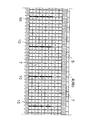
【図1】 路面の雨水等の浸透構造の第1実施例を示す断面図である。
【図2】 路面の雨水等の浸透構造の第2実施例を示す断面図である。
【図3】 路面の雨水等の浸透構造の縦断面図である。
【図4】 路面の雨水等の浸透構造の第3実施例を示す断面図である。
【図5】 路面の雨水等の浸透構造の第3実施例を示す縦断面図である。
【図6】 ブロック構造体の部分断面図である。
【符号の説明】
1 雨水等の浸透構造
2 路面
3 不透水層の舗装路面
4 透水層の舗装路面
5 砕石層
6 ブロック構造体
7 遮水板
8 遮水シート
9 下部層[0001]
BACKGROUND OF THE INVENTION
The present invention relates to an improvement of a penetration structure for rainwater or the like that can be used as a side groove on a road surface.
[0002]
[Prior art]
Conventionally, as a permeation structure such as rain water on the road surface, for example, a side groove formed of a U-shaped groove was used, but as in JP-A-5-214760, the internal space of the side groove main body is a rainwater discharge space, Divided into rainwater storage spaces, each of which has a water flow section, some quickly flow down through the rainwater discharge space, and the rest is temporarily retained in the rainwater storage space and infiltrated into the ground sequentially. The structure to be made is known.
[0003]
[Problems to be solved by the invention]
However, these have drawbacks that the internal structure becomes complicated and that it is difficult to form them in an arbitrary size.
The present invention has been made in view of such circumstances, and its main problem is that a large number of container-like members are connected vertically and horizontally to assemble and bury a block structure of a desired size and shield it. A water member is provided so that it can be used as a permeation structure for rainwater or the like such as a side groove that permeates water underground.
[0004]
[Means for Solving the Problems]
In order to solve the above-mentioned problems, the present invention is characterized in that in the invention of
The block structure is provided with a water-impervious member that is vertically divided at an appropriate interval in the extending direction to form a plurality of compartments, and a lower permeable layer formed below the block structure is provided in each compartment. In infiltration structure such as rainwater that can infiltrate the accumulated water,
The block structure has a large container-like member arranged in the upper stage, and a small container-like member is stacked below it.
The water shielding member is provided in the stacking portion of the small container-like member, and when the water accumulated in the block structure reaches a level higher than the upper end of the water shielding member, it passes over the water shielding member and flows into the adjacent compartment. Alternatively, a technical measure is taken such that it flows in the extending direction of the block structure through the upper portion made of a large container-like member.
In the invention of
The road surface is formed into a first surface layer portion having water impermeability and a second surface layer portion having water permeability at one side end, and the first surface layer portion has a surface inclined downward toward the second surface layer portion. Therefore, the technical means of forming a storage part that collects the water that has permeated and permeated into the second surface layer part into the block structure is taken.
In the invention of
A block structure in which container-like members are connected vertically and horizontally is buried in the ground, and water that has permeated the surface layer portion is collected in the block structure to form a storage portion, and an impermeable layer is formed on the side of the block structure. Water shielding that is provided or covered with a water shielding sheet so that the water accumulated in the block structure does not flow outward from the side surface, and the block structure partitions vertically at an appropriate interval in the extending direction. In the permeation structure such as rain water that can permeate the water stored in each compartment into the lower permeable layer formed below the block structure by providing a member and forming a plurality of compartments,
The surface layer portion forming the road surface has water permeability to form a surface water permeable layer, and a block structure in which container-like members are connected vertically and horizontally below a predetermined portion of the surface water permeable layer is embedded. The other part of the surface permeable layer is formed with an impermeable layer below or covered with a water shielding sheet so that the bottom surface of the surface permeable layer is gradually lowered to contact the upper part of the block structure. The technical means of forming and forming the storage part which collects the water which permeated the said surface part water permeable layer and collects in a block structure is taken.
[0005]
DETAILED DESCRIPTION OF THE INVENTION
A preferred embodiment of a rainwater penetration structure according to the present invention will be described below with reference to the drawings.
In FIG. 1, a
That is, the
[0006]
The
A crushed
And the crushed
In the present embodiment, a similar crushed
Therefore, since it can be configured in the same manner as the structure of the pavement surface of a normal roadway except for the side grooves, there is no problem in operating the vehicle.
[0007]
A
Here, the container-like member is not particularly limited, but in this embodiment, the container-like member has a bowl shape with an open upper surface, and the side surface is formed in a tapered shape so that the width is gradually narrowed downward with a substantially square cross section. In addition, a large number of holes are formed in the side surface and the bottom surface.
[0008]
Further, a reinforcing hollow
As illustrated in FIG. 6, a hard (metal, hard plastic, or the like)
The container-
In other words, a large number of them are stacked up and down by alternately inverting them vertically.
In the example shown in the figure, the uppermost stage is arranged so that the bottom surface faces upward, but if the opening faces upward, a protective plate (not shown) having water permeability is placed so as to cover the opening and buried. can do.
This protective plate can be used in the same manner even when the normal uppermost opening faces downward.
Each container-
This
[0009]
That is, in this embodiment, as shown in FIG. 6, a
Further, when a layer having water permeability is formed below the paved road surface, the layer having the water permeability, in the illustrated example, below the crushed
Here, if the
Thereby, since water does not permeate downward at least in the main part of the roadway, there is no fear of the ground softening.
[0010]
On the other hand, when water may permeate into the ground below the sidewalk side, it is not necessary to provide the above-described water shielding plate or water shielding sheet. .
The bottom surface of the
[0011]
Therefore, the rain that has fallen on the road surface is collected on the paved
In addition, water leaking from the gaps in the bottom surface of the block structure 6 (holes of the container-like members and the gaps between the container-like members) permeates the ground below it, so that the water accumulated in the
[0012]
In the
A crushed
And the
Moreover, in the
[0013]
Further, instead of the water shielding plate or the
As a result, the water that permeates the
Since other configurations and operations are the same as those in the above-described embodiment, the same components are denoted by the same reference numerals and description thereof is omitted.
[0014]
As shown in FIG. 3, the
In the illustrated example, the
Therefore, when the water stored in the
[0015]
As a result, when the ground under the
As a result, on the upstream side, the water in the
[0016]
Next, the infiltration structure such as rain water on the road surface shown in FIGS. 4 and 5 is a modification of the embodiment of FIG.
That is, in this embodiment, the
The
Therefore, when a large amount of water accumulates, the portion with the high water level is in the
On the contrary, since the low water level is in the small container-
[0017]
In this
In the illustrated example, the
Therefore, when the water stored in the
[0018]
As a result, when the ground under the
As a result, on the upstream side, the water in the
Since other configurations are the same as those in the embodiment of FIG. 1, the same reference numerals are given to the same configurations, and description thereof is omitted.
[0019]
In the above-described embodiment, the structure for allowing water to gradually permeate into the ground downward in the block structure is illustrated, but the bottom surface may be covered with a water shielding member or a water shielding sheet so as not to penetrate.
In that case, since the block structure becomes a complete storage part, a mouth part for drainage may be provided so that the water in the storage part can be drained (in the case of permeation as in the above embodiment). A drainage mouth may be provided).
Moreover, in the said Example, although the case where the drainage structure was arrange | positioned in the side end of the road surface was illustrated, the position is not specifically limited, A center, a midway position, etc. can be set arbitrarily.
Furthermore, the road surface is not limited to a roadway, and may be a sidewalk, a park, a plaza, a ground, a parking lot, or any other place.
In addition, it goes without saying that various design changes can be made to the present invention without departing from the scope of the invention.
[0020]
【The invention's effect】
In this invention comprised as mentioned above, the block structure of arbitrary magnitude | sizes can be assembled by using a container-shaped member, and it is excellent in versatility.
Further, since the strength is high and the porosity is also high, efficient water storage can be performed.
Moreover, by providing a partition to the block structure to form a compartment, water can gradually permeate into the ground even if the lower part of the block structure has an inclined surface.
If a large container-like member is combined with the upper stage, the large container-like member becomes a large space, so that water can be quickly flowed down to the drain outlet and drained.
[Brief description of the drawings]
FIG. 1 is a cross-sectional view showing a first embodiment of a permeation structure for rainwater or the like on a road surface.
FIG. 2 is a cross-sectional view showing a second embodiment of a permeation structure for rainwater or the like on a road surface.
FIG. 3 is a longitudinal sectional view of a permeation structure such as rainwater on a road surface.
FIG. 4 is a cross-sectional view showing a third embodiment of a permeation structure for rainwater or the like on a road surface.
FIG. 5 is a longitudinal sectional view showing a third embodiment of a structure for infiltrating rainwater or the like on a road surface.
FIG. 6 is a partial cross-sectional view of a block structure.
[Explanation of symbols]
DESCRIPTION OF
Claims (3)
ブロック構造体が、延出方向に向かって適宜間隔で上下に仕切る遮水部材を設けて複数の区画室を形成して、ブロック構造体の下方に形成された下部透水層に、各区画室内に貯まった水を浸透させうる雨水等の浸透構造において、
前記ブロック構造体が、上段に大型の容器状部材を配置し、その下方に小型の容器状部材を積み重ねてなり、
遮水部材が小型の容器状部材の積み重ね部分に設けられており、ブロック構造体に貯まった水が遮水部材の上端より高い水位となると遮水部材を乗り越えて隣接する区画室に流入し、または大型の容器状部材からなる上段部分を通ってブロック構造体の延出方向へ流れるようになっていることを特徴とする雨水等の浸透構造。A block structure in which container-like members are connected vertically and horizontally is buried in the ground, and water that has permeated the surface layer portion is collected in the block structure to form a storage portion, and an impermeable layer is formed on the side of the block structure. It is formed so that the water accumulated in the block structure covered with a water shielding sheet does not flow out from the side,
The block structure is provided with a water-impervious member that is vertically divided at an appropriate interval in the extending direction to form a plurality of compartments, and a lower permeable layer formed below the block structure is provided in each compartment. In infiltration structure such as rainwater that can infiltrate the accumulated water,
The block structure has a large container-like member arranged in the upper stage, and a small container-like member is stacked below it.
The water shielding member is provided in the stacking portion of the small container-like member, and when the water accumulated in the block structure reaches a level higher than the upper end of the water shielding member, it passes over the water shielding member and flows into the adjacent compartment. Alternatively, a permeation structure for rainwater or the like, characterized in that it flows in the extending direction of the block structure through an upper portion made of a large container-like member.
前記路面を形成する表層部が透水性を有して表部透水層を形成しており、該表部透水層の所定個所の下方に容器状部材を縦横且つ上下に連結したブロック構造体を埋設し、表部透水層の他の個所は、その下方に不透水層を形成し、または遮水シートで覆い、表部透水層の底面を漸次下降して前記ブロック構造体の上部に接するように形成し、上記表部透水層に浸透した水をブロック構造体に集める貯留部を形成してなることを特徴とする雨水等の浸透構造。A block structure in which container-like members are connected vertically and horizontally is buried in the ground, and water that has permeated the surface layer portion is collected in the block structure to form a storage portion, and an impermeable layer is formed on the side of the block structure. Water shielding that is provided or covered with a water shielding sheet so that the water accumulated in the block structure does not flow outward from the side surface, and the block structure partitions vertically at an appropriate interval in the extending direction. In the permeation structure such as rain water that can permeate the water stored in each compartment into the lower permeable layer formed below the block structure by providing a member and forming a plurality of compartments,
The surface layer portion forming the road surface has water permeability to form a surface water permeable layer, and a block structure in which container-like members are connected vertically and horizontally below a predetermined portion of the surface water permeable layer is embedded. The other part of the surface permeable layer is formed with an impermeable layer below or covered with a water shielding sheet so that the bottom surface of the surface permeable layer is gradually lowered to contact the upper part of the block structure. An infiltration structure for rainwater or the like, characterized in that it forms and forms a reservoir that collects the water that has penetrated into the surface permeable layer into the block structure.
Priority Applications (1)
| Application Number | Priority Date | Filing Date | Title |
|---|---|---|---|
| JP34222198A JP4084479B2 (en) | 1998-12-01 | 1998-12-01 | Rainwater penetration structure |
Applications Claiming Priority (1)
| Application Number | Priority Date | Filing Date | Title |
|---|---|---|---|
| JP34222198A JP4084479B2 (en) | 1998-12-01 | 1998-12-01 | Rainwater penetration structure |
Publications (3)
| Publication Number | Publication Date |
|---|---|
| JP2000160667A JP2000160667A (en) | 2000-06-13 |
| JP2000160667A5 JP2000160667A5 (en) | 2006-01-19 |
| JP4084479B2 true JP4084479B2 (en) | 2008-04-30 |
Family
ID=18352063
Family Applications (1)
| Application Number | Title | Priority Date | Filing Date |
|---|---|---|---|
| JP34222198A Expired - Fee Related JP4084479B2 (en) | 1998-12-01 | 1998-12-01 | Rainwater penetration structure |
Country Status (1)
| Country | Link |
|---|---|
| JP (1) | JP4084479B2 (en) |
Families Citing this family (4)
| Publication number | Priority date | Publication date | Assignee | Title |
|---|---|---|---|---|
| JP4772662B2 (en) * | 2006-12-28 | 2011-09-14 | 株式会社オーイケ | Osmosis system and construction method thereof |
| JP4942584B2 (en) * | 2007-08-28 | 2012-05-30 | 積水化学工業株式会社 | Storage penetration unit connection structure |
| JP6106643B2 (en) * | 2014-08-25 | 2017-04-05 | 中川 武志 | Underpass structure of road |
| CN108842566A (en) * | 2018-07-09 | 2018-11-20 | 天津大学 | Wisdom reservoir catchment system is descended in a kind of city on a large scale |
-
1998
- 1998-12-01 JP JP34222198A patent/JP4084479B2/en not_active Expired - Fee Related
Also Published As
| Publication number | Publication date |
|---|---|
| JP2000160667A (en) | 2000-06-13 |
Similar Documents
| Publication | Publication Date | Title |
|---|---|---|
| EP2071079A1 (en) | Infiltration system | |
| WO1995016833A1 (en) | Underground drainage system | |
| JP4284665B2 (en) | Drainage structure of gutter | |
| EP1243698A1 (en) | Road bed structure | |
| JP4084479B2 (en) | Rainwater penetration structure | |
| JP4084478B2 (en) | Drainage structure of road surface | |
| JP2000104206A (en) | Pavement slab and structure of pavement and sidewalk using same | |
| JPH08260553A (en) | Side ditch structure for infiltrating water | |
| KR100804066B1 (en) | Drainage structure for artificial ground enabling efficient water drain and improving structure strength of the artificial ground | |
| KR101083032B1 (en) | Pavement | |
| JP2005097858A (en) | Draining block, and pavement structure using the same | |
| JP2000303546A (en) | Draining structure of pavement | |
| JP3665792B2 (en) | Paved road structure | |
| JP3143652B2 (en) | Temporary storage tank for rainwater, etc. | |
| KR101186881B1 (en) | A Porous And Water Permeable Boundary Stone And Drainage System Using It | |
| JP4206006B2 (en) | Side groove block for permeable pavement | |
| KR200224492Y1 (en) | A Percolation Concrete Block for Side Gutter | |
| JP2005226396A (en) | Integral culvert block and drainage structure of road side edge | |
| JPH0784758B2 (en) | Drainage structure of asphalt pavement concrete slab | |
| JP2006097229A (en) | Pavement plate and pavement structure using the same | |
| CN112982075B (en) | City environmental protection road surface | |
| JP2753884B2 (en) | Underground storage and infiltration method using honeycomb-shaped plates | |
| JPH1018362A (en) | Underground water storage tank | |
| JPH0860736A (en) | Street gutter lid for water permeable paved road surface | |
| JP2775392B2 (en) | Gutter for permeable pavement |
Legal Events
| Date | Code | Title | Description |
|---|---|---|---|
| A521 | Written amendment |
Free format text: JAPANESE INTERMEDIATE CODE: A523 Effective date: 20051125 |
|
| A621 | Written request for application examination |
Free format text: JAPANESE INTERMEDIATE CODE: A621 Effective date: 20051125 |
|
| A977 | Report on retrieval |
Free format text: JAPANESE INTERMEDIATE CODE: A971007 Effective date: 20070913 |
|
| A131 | Notification of reasons for refusal |
Free format text: JAPANESE INTERMEDIATE CODE: A131 Effective date: 20070919 |
|
| A521 | Written amendment |
Free format text: JAPANESE INTERMEDIATE CODE: A523 Effective date: 20071119 |
|
| TRDD | Decision of grant or rejection written | ||
| A01 | Written decision to grant a patent or to grant a registration (utility model) |
Free format text: JAPANESE INTERMEDIATE CODE: A01 Effective date: 20080130 |
|
| A61 | First payment of annual fees (during grant procedure) |
Free format text: JAPANESE INTERMEDIATE CODE: A61 Effective date: 20080215 |
|
| R150 | Certificate of patent or registration of utility model |
Free format text: JAPANESE INTERMEDIATE CODE: R150 |
|
| FPAY | Renewal fee payment (event date is renewal date of database) |
Free format text: PAYMENT UNTIL: 20110222 Year of fee payment: 3 |
|
| FPAY | Renewal fee payment (event date is renewal date of database) |
Free format text: PAYMENT UNTIL: 20110222 Year of fee payment: 3 |
|
| FPAY | Renewal fee payment (event date is renewal date of database) |
Free format text: PAYMENT UNTIL: 20110222 Year of fee payment: 3 |
|
| S111 | Request for change of ownership or part of ownership |
Free format text: JAPANESE INTERMEDIATE CODE: R313113 |
|
| FPAY | Renewal fee payment (event date is renewal date of database) |
Free format text: PAYMENT UNTIL: 20110222 Year of fee payment: 3 |
|
| R360 | Written notification for declining of transfer of rights |
Free format text: JAPANESE INTERMEDIATE CODE: R360 |
|
| FPAY | Renewal fee payment (event date is renewal date of database) |
Free format text: PAYMENT UNTIL: 20110222 Year of fee payment: 3 |
|
| FPAY | Renewal fee payment (event date is renewal date of database) |
Free format text: PAYMENT UNTIL: 20110222 Year of fee payment: 3 |
|
| R370 | Written measure of declining of transfer procedure |
Free format text: JAPANESE INTERMEDIATE CODE: R370 |
|
| FPAY | Renewal fee payment (event date is renewal date of database) |
Free format text: PAYMENT UNTIL: 20110222 Year of fee payment: 3 |
|
| S111 | Request for change of ownership or part of ownership |
Free format text: JAPANESE INTERMEDIATE CODE: R313113 |
|
| FPAY | Renewal fee payment (event date is renewal date of database) |
Free format text: PAYMENT UNTIL: 20110222 Year of fee payment: 3 |
|
| R350 | Written notification of registration of transfer |
Free format text: JAPANESE INTERMEDIATE CODE: R350 |
|
| FPAY | Renewal fee payment (event date is renewal date of database) |
Free format text: PAYMENT UNTIL: 20130222 Year of fee payment: 5 |
|
| FPAY | Renewal fee payment (event date is renewal date of database) |
Free format text: PAYMENT UNTIL: 20130222 Year of fee payment: 5 |
|
| FPAY | Renewal fee payment (event date is renewal date of database) |
Free format text: PAYMENT UNTIL: 20140222 Year of fee payment: 6 |
|
| R250 | Receipt of annual fees |
Free format text: JAPANESE INTERMEDIATE CODE: R250 |
|
| R250 | Receipt of annual fees |
Free format text: JAPANESE INTERMEDIATE CODE: R250 |
|
| R250 | Receipt of annual fees |
Free format text: JAPANESE INTERMEDIATE CODE: R250 |
|
| R250 | Receipt of annual fees |
Free format text: JAPANESE INTERMEDIATE CODE: R250 |
|
| LAPS | Cancellation because of no payment of annual fees |