JP4084449B2 - Control device for mobile crane - Google Patents
Control device for mobile crane Download PDFInfo
- Publication number
- JP4084449B2 JP4084449B2 JP27953997A JP27953997A JP4084449B2 JP 4084449 B2 JP4084449 B2 JP 4084449B2 JP 27953997 A JP27953997 A JP 27953997A JP 27953997 A JP27953997 A JP 27953997A JP 4084449 B2 JP4084449 B2 JP 4084449B2
- Authority
- JP
- Japan
- Prior art keywords
- spring lock
- solenoid valve
- spring
- check valve
- pilot check
- Prior art date
- Legal status (The legal status is an assumption and is not a legal conclusion. Google has not performed a legal analysis and makes no representation as to the accuracy of the status listed.)
- Expired - Fee Related
Links
Images


Description
【0001】
【発明の属する技術分野】
本発明は、リーフスプリングからなるサスペンションのスプリングロック装置を有する移動式クレーンの制御装置に関する。
【0002】
【従来の技術】
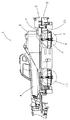
図3にリーフスプリングからなるサスペンションのスプリングロック装置を有する移動式クレーンの全体図を示す。1は移動式クレーンの全体であって、車両部2、旋回台部3、ブーム部4から構成されている。車両部2は、車両フレーム5、動力発生部6、サスペンション部7等から構成されている。さらにサスペンション部7は車両フレーム5と車軸8の間に縣架されたリーフスプリング9と、スプリングロックシリンダ10を有している。リーフスプリング9と、スプリングロックシリンダ10は前後左右に配置された4本のタイヤ11の内側4か所に設置されている。
【0003】
図4はスプリングロックシリンダ10に関係する部分の油圧回路図である。スプリングロックシリンダ10の伸び側油室につながる管路21は、4か所の同じ管路が合流してタンク管路22につながっている。スプリングロックシリンダ10の縮み側油室につながる管路26は、パイロットチェック弁20を介し、4か所の同じ管路が合流してスプリングロック用ソレノイド弁27につながっている。スプリングロック用ソレノイド弁27はタンク管路24と圧力管路25につながり、非通電時は内蔵するバネによってロ側に位置しており、管路23はタンク管路24とつながっている。パイロットチェック弁20につながるパイロット管路30は、4か所の同じ管路が合流してパイロット管路31につながり、さらにパイロットチェック弁用ソレノイド弁32につながっている。パイロットチェック弁用ソレノイド弁32はタンク管路34と圧力管路33につながり、非通電時は内蔵するバネによってロ側に位置しており、パイロット管路31は圧力管路33とつながっている。40は制御装置であって、スプリングロック用ソレノイド弁27とパイロットチェック弁用ソレノイド弁32に駆動信号を送るようになっている。
【0004】
図4の状態は移動式クレーン1の走行時の状態を示しており、制御装置40からは、スプリングロック用ソレノイド弁27とパイロットチェック弁用ソレノイド弁32に駆動信号が送られていない状態であって、スプリングロックシリンダ10の伸び側油室は管路21−管路22を経てタンクにつながっている。また、パイロットチェック弁20には、圧力管路33から、パイロットチェック弁用ソレノイド弁32を介してパイロット管路31−パイロット管路30を経て、パイロット圧がかかっており、内部のチェック弁は両方向の流れを許容する状態となっている。そのため、スプリングロックシリンダ10の縮み側油室につながる管路26は、パイロットチェック弁20を介して管路23−管路24を経て、タンクにつながっている。
【0005】
上記の状態においては、スプリングロックシリンダ10の両油室はタンクにつながっているため、自由に伸び縮み可能であって、走行時の車両フレーム5と車軸8間の距離変化に追随可能となっているのである。
【0006】
オンタイヤ作業あるいは、アウトリガ作業時にジャッキシリンダ縮小させ、オンタイヤ状態となったときにはクレーンの後方安定が確保されていることが重要である。そのため、上記作業時にはスプリングロックされていることが必要である。
【0007】
図4において、スプリングロックするには、まず制御装置40から、スプリングロック用ソレノイド弁27とパイロットチェック弁用ソレノイド弁32に駆動信号が出される。スプリングロック用ソレノイド弁27はイ位置に切り替わり、管路23は圧力管路25につながるため、スプリングロックシリンダ10はパイロットチェック弁20−管路26を介して、縮み側油室に圧力管路25の圧力がかかり、縮小を始める。また、パイロットチェック弁用ソレノイド弁32はイ位置に切り替わり、パイロット管路31はタンク管路34につながるため、パイロット管路30を経て、パイロットチェック弁20に作用していたパイロット圧が無くなるため、パイロットチェック弁20はスプリングロックシリンダ10の縮み側油室へ向かう一方向にしか作動油を流さなくなるのである。スプリングロック用ソレノイド弁27に駆動信号が出されている間、スプリングロックシリンダ10は、車両フレーム5と車軸8の間に縣架されたリーフスプリング9をたわませながら、車軸8が車両フレーム5に接するまで縮小を続けるのである。スプリングロック用ソレノイド弁27への駆動信号が出なくなっても、パイロットチェック弁用ソレノイド弁32への駆動信号を出しつづけることにより、スプリングロックシリンダ10の伸びを規制し、スプリングロック状態を維持するのである。スプリングロックの開放にあたっては、上記スプリングロック状態では、駆動信号が出され続けていたパイロットチェック弁用ソレノイド弁32への駆動信号を停止する。すると、パイロットチェック弁用ソレノイド弁32は、内蔵するバネによってロ位置に切り替わり、再びパイロット油圧はパイロット管路31−パイロット管路30を経てパイロットチェック弁に作用するため、たわめられていたリーフスプリング9の力によりスプリングロックシリンダ10は伸びようとし、スプリングロックシリンダ10の縮み側油室の油は、管路26−パイロットチェック弁20−管路23−管路24を経てタンクに戻ることができるようになり、走行状態にもどるのである。
【0008】
図5は制御部のブロック図である。41は自動復帰接点からなるスプリングロックスイッチである。自動復帰接点からなるスイッチを使用する理由は、スプリングロック作動中になんらかの危険な状態が発生して作動を停止しようとする場合、自動復帰接点だと手をスイッチから離すだけでよく、すばやい作動停止が可能だからである。42はアウトリガ操作スイッチ、46はスプリングロックインジケータランプ、43はクレーン作動規制手段である。クレーン作動規制手段43は旋回、ブーム起伏、ブーム伸縮、ウインチ巻上げ巻下げ、といったクレーン作動を規制する手段である。44は上部コントローラであって、前記スプリングロックスイッチ41および、アウトリガ操作スイッチ42からの操作信号を受取り、また、前記スプリングロックインジケータランプ46、および、クレーン作動規制手段43へ駆動信号を送るのである。上記の構成要素は旋回台あるいはクレーンキャブ内に設置されている。以下の構成要素は車両部に設置されるもので、45は下部コントローラである。前記上部コントローラ44と下部コントローラ45は常時、相互に信号のやりとりを行っている。27はスプリングロック用ソレノイド弁であり、32はパイロットチェック弁用ソレノイド弁であって、図4で説明したものである。48はアウトリガ規制手段である。スプリングロック用ソレノイド弁27、パイロットチェック弁用ソレノイド弁32およびアウトリガ規制手段48は前記下部コントローラ45からの駆動信号によって駆動されるのである。
【0009】
図6は上記制御装置の作動を説明するタイムチャートである。最初にスプリングロックスイッチ41から入力があると、スプリングロック用ソレノイド弁27、パイロットチェック弁用ソレノイド弁32、およびスプリングロックインジケータランプ46への出力がなされ、スプリングロック作動が開始される。それと同時にクレーン作動規制手段43、およびアウトリガ作動規制手段48への出力がなくなり、両規制が解除され、図示しない各クレーン操作手段、およびアウトリガ操作手段43の操作によって、クレーン操作および、アウトリガ操作が可能となる。スプリングロックスイッチ41は自動復帰接点であるので、その後も任意の時間(T2秒)連続して押し続けられた後、スイッチ操作をやめると同時にスプリングロック用ソレノイド弁27への出力が断たれるのである。パイロットチェック弁用ソレノイド弁32および、スプリングロックインジケータランプ46への出力は継続したままであり、クレーン作動規制手段43および、アウトリガ作動規制手段48への出力も中断したままである。
【0010】
上記スプリングロックスイッチ41の操作時間(T2秒)はオペレータにまかされており、クレーンキャブから身を乗り出してスプリングロック作動状況を確認する、あるいは全くの勘で適当な時間操作するのが普通であった。
【0011】
【発明が解決しようとする課題】
しかし、この方式の場合には以上のように、クレーン作動規制手段および、アウトリガ規制手段が、スプリングロック作動開始すると同時に解除されてしまい、なおかつ、スプリングロック操作時間がオペレータ任せなため、中途半端なスプリングロック状態でもクレーン操作およびアウトリガ格納操作が可能であった。そのため、中途半端なスプリングロック状態でのオンタイヤ作業では、後方安定を確保できないため転倒する可能性があった。あるいはアウトリガ作業状態においても、中途半端なスプリングロック状態でのアウトリガジャッキ格納時には旋回台の旋回位置や起伏角度によっては後方安定を確保できない場合があり、同様に転倒する可能性があった。
【0012】
本発明は、以上のような事情に基づいてなされたものであり、従来の制御装置の基本構成を踏襲しながらも、安全性確保に優れた移動式クレーンの制御装置を提供しようとするものである。
【0013】
【課題を解決するための手段】
本願の請求項の発明は、上記の目的を達成するために、次のような課題解決手段を備えて構成されている。
【0016】
請求項1の発明の移動式クレーンの制御装置は、車両フレームと車軸の間に懸架されたリーフスプリングと、車両フレームと車軸の間に配置されクレーン作業時にリーフスプリングをたわませて車軸を車両フレームに固定するスプリングロックシリンダと、スプリングロックシリンダの伸びを規制しパイロット圧により開放されるパイロットチェック弁と、パイロットチェック弁のパイロット圧ポートに接続され圧力源からの作動油を送油切換え可能なパイロットチェック弁用ソレノイド弁と、スプリングロックシリンダ縮み側に接続され圧力源からの作動油を送油切換え可能なスプリングロック用ソレノイド弁からなる移動式クレーンのサスペンションに関し、自動復帰接点からなるスプリングロックスイッチからの操作信号がコントローラに入力されると、コントローラから出力される駆動信号により前記スプリングロック用ソレノイド弁とパイロットチェック弁用ソレノイド弁が切換わり、前記スプリングロックシリンダが縮小作動するものであり、かつ、前記スプリングロックスイッチからの操作信号がコントローラに入力されなくなると、前記スプリングロック用ソレノイド弁のみが切換わり、前記スプリングロックシリンダがその時点での縮小状態を保持するよう構成された移動式クレーンの制御装置において、前記コントローラは、スプリングロック用ソレノイド弁への駆動信号出力される時間を記録し、記録していた時間の合計が規定時間に達するとスプリングロック完了と判断し、解除信号を出力する出力状態モニタを有しており、当該出力状態モニタからの解除信号によりアウトリガ作動規制手段が作動規制解除されるよう構成されている。このため、確実なスプリングロック完了のもとにアウトリガ操作が可能となるのである。
【0017】
請求項2の発明の移動式クレーンの制御装置は、車両フレームと車軸の間に懸架されたリーフスプリングと、車両フレームと車軸の間に配置されクレーン作業時にリーフスプリングをたわませて車軸を車両フレームに固定するスプリングロックシリンダと、スプリングロックシリンダの伸びを規制しパイロット圧により開放されるパイロットチェック弁と、パイロットチェック弁のパイロット圧ポートに接続され圧力源からの作動油を送油切換え可能なパイロットチェック弁用ソレノイド弁と、スプリングロックシリンダ縮み側に接続され圧力源からの作動油を送油切換え可能なスプリングロック用ソレノイド弁からなる移動式クレーンのサスペンションに関し、自動復帰接点からなるスプリングロックスイッチからの操作信号がコントローラに入力されると、コントローラから出力される駆動信号により前記スプリングロック用ソレノイド弁とパイロットチェック弁用ソレノイド弁が切換わり、前記スプリングロックシリンダが縮小作動するものであり、かつ、前記スプリングロックスイッチからの操作信号がコントローラに入力されなくなると、前記スプリングロック用ソレノイド弁のみが切換わり、前記スプリングロックシリンダがその時点での縮小状態を保持するよう構成された移動式クレーンの制御装置において、前記コントローラは、スプリングロック用ソレノイド弁への駆動信号出力される時間を記録し、記録していた時間の合計が規定時間に達するとスプリングロック完了と判断し、解除信号を出力する出力状態モニタを有しており、当該出力状態モニタからの解除信号によりクレーン作動規制手段が作動規制解除されるよう構成されている。このため、確実なスプリングロック完了のもとにクレーン操作が可能となるのである。
【0018】
【発明の実施の形態】
本発明の実施の形態を説明するにあたって、従来の技術で図3および図6に図示し説明した移動式クレーンの制御装置に本発明を適用した例を以下に説明する。従って本発明と従来のものと共通する部分については、同符号を用い詳細な説明を略して、以下の本発明の実施の形態を説明する。
【0019】
図1に、本発明の実施の形態に係る制御部のブロック図を示す。51は上部コントローラであり、52は下部コントローラである。53は下部コントローラに内蔵されているリレー接点でありスプリングロック用ソレノイド弁27への駆動信号出力されるものである。54は前記リレー接点53の出力側に接続された出力状態モニタである。出力状態モニタ54は、前記リレー接点53が閉じられ、スプリングロック用ソレノイド弁27への駆動信号出力される時間を記録し、記録していた時間の合計が規定時間に達すると解除信号を出力するものである。
【0020】
図2は、本発明の実施の形態に係る制御部の作動を説明するタイムチャートである。左半分は基本作動を示していて、最初にスプリングロックスイッチ41から入力があって、T1秒後、スプリングロック用ソレノイド弁27、パイロットチェック弁用ソレノイド弁32、およびスプリングロックインジケータランプ46への出力がなされ、スプリングロック作動が開始される。スプリングロックスイッチ41からT1秒の連続した入力があってはじめて、スプリングロック操作がされたとコントローラが認識し、コントローラからの出力がされるのである。これは、誤操作による誤作動防止のためであって、T1秒は普通1〜2秒に設定されている。クレーン作動規制手段43、およびアウトリガ作動規制手段48への出力はこの時点では継続したままである。また、スプリングロックインジケータランプ46はこの時点で入力があると、点滅を開始する。
【0021】
さらに、スプリングロックスイッチ41を押しつづけていると、T秒後クレーン作動規制手段43、およびアウトリガ作動規制手段48への出力が停止し、スプリングロックインジケータランプ46は同時に点滅から連続点灯に切り替わる。これによって、オペレータはスプリングロック作動が完了したことを知り、スプリングロックスイッチ41を押すことを止めるのである。すると同時に、スプリングロック用ソレノイド弁27への出力が停止するのである。
【0022】
スプリングロック用ソレノイド弁27および、パイロットチェック弁用ソレノイド弁32への出力が開始してから、クレーン作動規制手段43、アウトリガ作動規制手段48および、スプリングロックインジケータランプ46への出力が終了するまでの上記時間(T秒)は、スプリングロックシリンダ10の必要油量と油圧ポンプの吐出量を考慮し、若干の余裕をみて、確実にスプリングロックが完了する時間を設定する。
【0023】
右半分はスプリングロックスイッチ41が断続操作されたときの作動を示している。最初にスプリングロックスイッチ41から入力があって、T1秒後、スプリングロック用ソレノイド弁27、パイロットチェック弁用ソレノイド弁32、およびスプリングロックインジケータランプ46への出力がなされ、スプリングロック作動が開始されたのち、上記設定された時間T秒よりも短いTe秒後にスプリングロックスイッチ41の操作が中断され操作信号入力がなくなると同時に、スプリングロック用ソレノイド27への駆動信号は出力されなくなり、スプリングロック作動は中断する。パイロットチェック弁用ソレノイド弁32へは出力されたままであるので、パイロットチェック弁20はスプリングロックシリンダ10の縮み側油室の油をブロックするので、スプリングロックシリンダ10はその時の長さを維持する。また、スプリングロックインジケータランプ46は、点滅したままであるので、オペレータはスプリングロックが完了していないことを知るのである。
【0024】
再度、スプリングロックスイッチ41を押すと、T1秒後、スプリングロック用ソレノイド弁27への駆動信号出力が再開され、スプリングロック作動が再開される。その後、T=Te+Tfとなる再開後のスプリングロック用ソレノイド弁27への出力時間Tfが経過すると、クレーン作動規制手段43、およびアウトリガ作動規制手段48への出力がなくなり、両規制が解除され、図示しない各クレーン操作手段、およびアウトリガ操作手段43の操作によって、クレーン操作および、アウトリガ操作が可能となるのである。また、スプリングロックインジケータランプ46は同時に点滅から連続点灯に切り替わる。これによって、オペレータはスプリングロック作動が完了したことを知り、スプリングロックスイッチ41を押すことを止めるのである。
【0025】
なお、上記実施の形態において、クレーン作動規制手段として説明したものは具体的には、パイロット圧によりリモコン操作されるクレーン操作装置のリモコン圧ベント用ソレノイド弁を対象に制御することによりその機能を達成できる。また、アウトリガ規制手段として説明したものは、アウトリガ用ソレノイド弁を制御するようにすればよいのである。
【0026】
また、スプリングロック作動は、リーフスプリング9のバネ力に抗してリーフスプリング9をたわませて車軸8を車両フレーム5に固定するわけであり、スプリングロックシリンダ10の出力はそれに充分なものに設定する必要がある。オンタイヤ状態では、車両重量によって、リーフスプリング9はすでにたわんでおり、それ以降のたわみ分の出力をスプリングロックシリンダ10が負担すればよいのであるが、アウトリガによりジャッキアップされた状態で、スプリングロックしようとすると、たわませるに要する出力をすべてスプリングロックシリンダ10が負担せねばならず非常に大きな出力が要求される。諸条件から、その出力を確保できない場合においても、本件発明においては、スプリングロック作動完了後、アウトリガ操作可能となるので、確実にオンタイヤ状態でスプリングロック作動されるため、小さなスプリングロックシリンダ出力でも完全なスプリングロックが確保されるのである。
【0027】
【発明の効果】
以上の如く構成し作用するものであるから、本願発明の移動式クレーンの制御装置では、スプリングロック用ソレノイド弁への出力時間を監視することによって完全なスプリングロック状態かどうかを判断できるのである。また、完全にスプリングロックした状態の時のみクレーン操作及び、アウトリガ操作が可能であるのでオンタイヤ作業時の後方安定および、アウトリガ作業時にジャッキを縮小する際の後方安定が確保されるので、クレーン作業が安全となるのである。そして、従来クレーンオペレータに課していたスプリングロック操作の注意義務をなくすことができるので、クレーンオペレータの疲労が軽減されるのである。
また、従来の制御装置の構成を基本的に流用できるので、コスト面でも優れた制御装置を提供できるのである。
【図面の簡単な説明】
【図1】本願の発明に係る移動式クレーンの制御部のブロック図である。
【図2】発明に係る移動式クレーンの制御部の作動を説明するタイムチャートである。
【図3】リーフスプリングからなるサスペンションのスプリングロック装置を有する移動式クレーンの全体図である。
【図4】スプリングロックシリンダに関係する部分の油圧回路図である。
【図5】従来の移動式クレーンの制御部のブロック図である。
【図6】従来の移動式クレーンの制御部の作動を説明するタイムチャートである。
【符号の説明】
1 移動式クレーン全体、2 車両部、3 旋回台部、4 ブーム部、5 車両フレーム、6 動力発生部、7 サスペンション部、8 車軸、9 リーフスプリング、10 スプリングロックシリンダ、11 タイヤ、20 パイロットチェック弁、21 23 26 管路、22 24 34 タンク管路、30 31 パイロット管路、25 33 圧力管路、27 スプリングロック用ソレノイド弁、32 パイロットチェック弁用ソレノイド弁、40 制御部、41 スプリングロックスイッチ、42 アウトリガ操作スイッチ、43 クレーン作動規制手段、44、51 上部コントローラ、45 52 下部コントローラ、46 スプリングロックインジケータランプ、48 アウトリガ規制手段、53リレー接点、54 出力状態モニタ[0001]
BACKGROUND OF THE INVENTION
The present invention relates to a control device for a mobile crane having a spring lock device for a suspension comprising a leaf spring.
[0002]
[Prior art]
FIG. 3 shows an overall view of a mobile crane having a spring lock device of a suspension composed of leaf springs. Reference numeral 1 denotes an entire mobile crane, which includes a vehicle unit 2, a swivel base unit 3, and a boom unit 4. The vehicle unit 2 includes a vehicle frame 5, a power generation unit 6, a suspension unit 7, and the like. Further, the suspension portion 7 has a leaf spring 9 suspended between the vehicle frame 5 and the axle 8 and a
[0003]
FIG. 4 is a hydraulic circuit diagram of a portion related to the
[0004]
The state of FIG. 4 shows a state when the mobile crane 1 is traveling, and is a state in which no drive signal is sent from the
[0005]
In the above state, since both oil chambers of the
[0006]
It is important that when the on-tire operation or the outrigger operation is performed, the jack cylinder is reduced and the rear stability of the crane is ensured when the on-tire state is reached. Therefore, it is necessary to be spring-locked during the above operation.
[0007]
In FIG. 4, in order to lock the spring, first, a drive signal is output from the
[0008]
FIG. 5 is a block diagram of the control unit.
[0009]
FIG. 6 is a time chart for explaining the operation of the control device. When there is an input from the
[0010]
The operation time (T2 seconds) of the
[0011]
[Problems to be solved by the invention]
However, in the case of this method, as described above, the crane operation restricting means and the outrigger restricting means are released at the same time when the spring lock operation is started, and the spring lock operation time is left to the operator, so it is halfway. Crane operation and outrigger storage operation were possible even in the spring lock state. Therefore, in the on-tire work in the halfway spring-locked state, there is a possibility of falling because the rear stability cannot be ensured. Alternatively, even in the outrigger work state, when the outrigger jack is stored in the halfway spring lock state, the rear stability may not be ensured depending on the swiveling position and the undulation angle of the swivel base, and there is a possibility of falling over.
[0012]
The present invention has been made based on the above circumstances, and intends to provide a mobile crane control device excellent in ensuring safety while following the basic configuration of a conventional control device. is there.
[0013]
[Means for Solving the Problems]
In order to achieve the above object, the invention of the claims of the present application includes the following problem solving means.
[0016]
According to a first aspect of the present invention, there is provided a mobile crane control device comprising: a leaf spring suspended between a vehicle frame and an axle; and a leaf spring disposed between the vehicle frame and the axle to deflect the axle when the crane is operated. A spring lock cylinder that is fixed to the frame, a pilot check valve that regulates the extension of the spring lock cylinder and is released by the pilot pressure, and is connected to the pilot pressure port of the pilot check valve so that hydraulic oil from the pressure source can be switched A spring lock switch consisting of an automatic return contact for a suspension of a mobile crane consisting of a solenoid valve for a pilot check valve and a spring lock solenoid valve that is connected to the spring lock cylinder contraction side and can switch hydraulic oil from a pressure source. The operation signal from The solenoid valve for a spring lock and the solenoid valve for a pilot check valve are switched by a drive signal output from a controller, the spring lock cylinder is operated to reduce, and from the spring lock switch When the operation signal is not input to the controller, only the solenoid valve for the spring lock is switched, and the controller for the mobile crane configured so that the spring lock cylinder maintains the contracted state at that time is provided. Has an output status monitor that records the time that the drive signal is output to the solenoid valve for spring lock, determines that spring lock is complete when the total of the recorded time reaches the specified time, and outputs a release signal Solution from the output status monitor. Outrigger actuation restricting means is configured to be deactivated regulated by signal. For this reason, the outrigger operation can be performed with the reliable completion of the spring lock.
[0017]
According to a second aspect of the present invention, there is provided a mobile crane control device comprising: a leaf spring suspended between a vehicle frame and an axle; a leaf spring disposed between the vehicle frame and the axle; A spring lock cylinder that is fixed to the frame, a pilot check valve that regulates the extension of the spring lock cylinder and is released by the pilot pressure, and is connected to the pilot pressure port of the pilot check valve so that hydraulic oil from the pressure source can be switched A spring lock switch consisting of an automatic return contact for a suspension of a mobile crane consisting of a solenoid valve for a pilot check valve and a spring lock solenoid valve that is connected to the spring lock cylinder contraction side and can switch hydraulic oil from a pressure source. The operation signal from The solenoid valve for a spring lock and the solenoid valve for a pilot check valve are switched by a drive signal output from a controller, the spring lock cylinder is operated to reduce, and from the spring lock switch When the operation signal is not input to the controller, only the solenoid valve for the spring lock is switched, and the controller for the mobile crane configured so that the spring lock cylinder maintains the contracted state at that time is provided. Has an output status monitor that records the time that the drive signal is output to the solenoid valve for spring lock, determines that spring lock is complete when the total of the recorded time reaches the specified time, and outputs a release signal Solution from the output status monitor. Crane operation regulating means is configured to be deactivated regulated by signal. For this reason, it is possible to operate the crane with complete completion of the spring lock.
[0018]
DETAILED DESCRIPTION OF THE INVENTION
In describing an embodiment of the present invention, an example in which the present invention is applied to a control apparatus for a mobile crane illustrated and described in FIGS. 3 and 6 in the prior art will be described below. Accordingly, the same reference numerals are used for portions common to the present invention and the conventional ones, and a detailed description thereof is omitted, and the following embodiments of the present invention are described.
[0019]
FIG. 1 shows a block diagram of a control unit according to the embodiment of the present invention. 51 is an upper controller, and 52 is a lower controller. 53 is a relay contact incorporated in the lower controller and outputs a drive signal to the spring
[0020]
FIG. 2 is a time chart for explaining the operation of the control unit according to the embodiment of the present invention. The left half shows basic operation. First, there is an input from the
[0021]
Furthermore, if the
[0022]
From the start of output to the
[0023]
The right half shows the operation when the
[0024]
When the
[0025]
In the above-described embodiment, what has been described as the crane operation restricting means is specifically achieved by controlling the solenoid valve for remote control pressure vent of the crane operating device that is remotely controlled by pilot pressure. it can. Further, what has been described as the outrigger restricting means may be such that the outrigger solenoid valve is controlled.
[0026]
In the spring lock operation, the leaf spring 9 is deflected against the spring force of the leaf spring 9 to fix the axle 8 to the vehicle frame 5, and the output of the
[0027]
【The invention's effect】
Since the mobile crane control device of the present invention is configured and operates as described above, it is possible to determine whether or not it is in the complete spring lock state by monitoring the output time to the spring lock solenoid valve. In addition, crane operation and outrigger operation are possible only when the spring is completely locked, ensuring rear stability during on-tire work and rear stability when the jack is reduced during outrigger work. Is safe. And since the duty to pay attention to the spring lock operation conventionally imposed on the crane operator can be eliminated, the fatigue of the crane operator is reduced.
Further, since the configuration of the conventional control device can be basically used, a control device that is excellent in terms of cost can be provided.
[Brief description of the drawings]
FIG. 1 is a block diagram of a control unit of a mobile crane according to the present invention.
FIG. 2 is a time chart for explaining the operation of the control unit of the mobile crane according to the invention.
FIG. 3 is an overall view of a mobile crane having a spring lock device of a suspension composed of leaf springs.
FIG. 4 is a hydraulic circuit diagram of a portion related to a spring lock cylinder.
FIG. 5 is a block diagram of a control unit of a conventional mobile crane.
FIG. 6 is a time chart for explaining the operation of a control unit of a conventional mobile crane.
[Explanation of symbols]
1 Overall mobile crane, 2 vehicle section, 3 swivel base section, 4 boom section, 5 vehicle frame, 6 power generation section, 7 suspension section, 8 axle, 9 leaf spring, 10 spring lock cylinder, 11 tire, 20 pilot check Valve, 21 23 26 pipe, 22 24 34 tank pipe, 30 31 pilot pipe, 25 33 pressure pipe, 27 spring lock solenoid valve, 32 pilot check valve solenoid valve, 40 controller, 41 spring lock switch , 42 Outrigger operation switch, 43 Crane operation restriction means, 44, 51 Upper controller, 45 52 Lower controller, 46 Spring lock indicator lamp, 48 Outrigger restriction means, 53 relay contact, 54 Output status monitor
Claims (2)
自動復帰接点からなるスプリングロックスイッチからの操作信号がコントローラに入力されると、コントローラから出力される駆動信号により前記スプリングロック用ソレノイド弁とパイロットチェック弁用ソレノイド弁が切換わり、前記スプリングロックシリンダが縮小作動するものであり、かつ、前記スプリングロックスイッチからの操作信号がコントローラに入力されなくなると、前記スプリングロック用ソレノイド弁のみが切換わり、前記スプリングロックシリンダがその時点での縮小状態を保持するよう構成された移動式クレーンの制御装置において、
前記コントローラは、スプリングロック用ソレノイド弁への駆動信号出力される時間を記録し、記録していた時間の合計が規定時間に達するとスプリングロック完了と判断し、解除信号を出力する出力状態モニタを有しており、当該出力状態モニタからの解除信号によりアウトリガ作動規制手段が作動規制解除されることを特徴とする移動式クレーンの制御装置。A leaf spring suspended between the vehicle frame and the axle, a spring lock cylinder that is disposed between the vehicle frame and the axle, deflects the leaf spring during crane operation, and fixes the axle to the vehicle frame, and an extension of the spring lock cylinder A pilot check valve that is released by the pilot pressure, a pilot check valve solenoid valve that is connected to the pilot pressure port of the pilot check valve and that can switch the hydraulic oil from the pressure source, and a spring lock cylinder contraction side With regard to the suspension of a mobile crane consisting of a solenoid valve for a spring lock that is connected and can switch hydraulic oil from a pressure source,
When an operation signal from a spring lock switch comprising an automatic return contact is input to the controller, the spring lock solenoid valve and the pilot check valve solenoid valve are switched by the drive signal output from the controller, and the spring lock cylinder is When the operation signal is reduced and the operation signal from the spring lock switch is not input to the controller, only the solenoid valve for the spring lock is switched, and the spring lock cylinder maintains the reduced state at that time. In the mobile crane control device configured as described above,
The controller records the time during which the drive signal is output to the spring lock solenoid valve, determines that the spring lock is complete when the total of the recorded times reaches a specified time, and outputs an output status monitor that outputs a release signal. The mobile crane control device is characterized in that the outrigger operation restriction means is released from the operation restriction by a release signal from the output state monitor.
自動復帰接点からなるスプリングロックスイッチからの操作信号がコントローラに入力されると、コントローラから出力される駆動信号により前記スプリングロック用ソレノイド弁とパイロットチェック弁用ソレノイド弁が切換わり、前記スプリングロックシリンダが縮小作動するものであり、かつ、前記スプリングロックスイッチからの操作信号がコントローラに入力されなくなると、前記スプリングロック用ソレノイド弁のみが切換わり、前記スプリングロックシリンダがその時点での縮小状態を保持するよう構成された移動式クレーンの制御装置において、
前記コントローラは、スプリングロック用ソレノイド弁への駆動信号出力される時間を記録し、記録していた時間の合計が規定時間に達するとスプリングロック完了と判断し、解除信号を出力する出力状態モニタを有しており、当該出力状態モニタからの解除信号によりクレーン作動規制手段が作動規制解除されることを特徴とする移動式クレーンの制御装置。A leaf spring suspended between the vehicle frame and the axle, a spring lock cylinder that is disposed between the vehicle frame and the axle, deflects the leaf spring during crane operation, and fixes the axle to the vehicle frame, and an extension of the spring lock cylinder A pilot check valve that is released by the pilot pressure, a pilot check valve solenoid valve that is connected to the pilot pressure port of the pilot check valve and that can switch the hydraulic oil from the pressure source, and a spring lock cylinder contraction side With regard to the suspension of a mobile crane consisting of a solenoid valve for a spring lock that is connected and can switch hydraulic oil from a pressure source,
When an operation signal from a spring lock switch comprising an automatic return contact is input to the controller, the spring lock solenoid valve and the pilot check valve solenoid valve are switched by the drive signal output from the controller, and the spring lock cylinder is When the operation signal is reduced and the operation signal from the spring lock switch is not input to the controller, only the solenoid valve for the spring lock is switched, and the spring lock cylinder maintains the reduced state at that time. In the mobile crane control device configured as described above,
The controller records the time during which the drive signal is output to the spring lock solenoid valve, determines that the spring lock is complete when the total of the recorded times reaches a specified time, and outputs an output status monitor that outputs a release signal. The mobile crane control device is characterized in that the crane operation restriction means is released from the operation restriction by a release signal from the output state monitor.
Priority Applications (1)
| Application Number | Priority Date | Filing Date | Title |
|---|---|---|---|
| JP27953997A JP4084449B2 (en) | 1997-09-26 | 1997-09-26 | Control device for mobile crane |
Applications Claiming Priority (1)
| Application Number | Priority Date | Filing Date | Title |
|---|---|---|---|
| JP27953997A JP4084449B2 (en) | 1997-09-26 | 1997-09-26 | Control device for mobile crane |
Publications (2)
| Publication Number | Publication Date |
|---|---|
| JPH1192085A JPH1192085A (en) | 1999-04-06 |
| JP4084449B2 true JP4084449B2 (en) | 2008-04-30 |
Family
ID=17612413
Family Applications (1)
| Application Number | Title | Priority Date | Filing Date |
|---|---|---|---|
| JP27953997A Expired - Fee Related JP4084449B2 (en) | 1997-09-26 | 1997-09-26 | Control device for mobile crane |
Country Status (1)
| Country | Link |
|---|---|
| JP (1) | JP4084449B2 (en) |
Families Citing this family (2)
| Publication number | Priority date | Publication date | Assignee | Title |
|---|---|---|---|---|
| CN1311169C (en) * | 2002-12-27 | 2007-04-18 | 日立建机株式会社 | Hydraulic circuit of working trunk |
| JP4219900B2 (en) | 2002-12-27 | 2009-02-04 | 日立建機株式会社 | Hydraulic cylinder drive device for work |
-
1997
- 1997-09-26 JP JP27953997A patent/JP4084449B2/en not_active Expired - Fee Related
Also Published As
| Publication number | Publication date |
|---|---|
| JPH1192085A (en) | 1999-04-06 |
Similar Documents
| Publication | Publication Date | Title |
|---|---|---|
| JP5658075B2 (en) | Exhaust gas purification system for work equipment | |
| JP2012047107A (en) | Exhaust gas cleaning system of working vehicle | |
| JP4084449B2 (en) | Control device for mobile crane | |
| JP5572826B2 (en) | Exhaust gas purification system | |
| JP4290861B2 (en) | Crane hydraulic circuit | |
| JP5486426B2 (en) | Exhaust gas purification device for work vehicle | |
| KR100876980B1 (en) | hydraulic circuit of having boom float position | |
| JP2000351585A (en) | Brake device for winch | |
| JP2002005122A (en) | Driving device of hydraulic motor | |
| JP2009019534A (en) | Exhaust emission control device of working vehicle | |
| KR100238847B1 (en) | Safety system of a boom for a pump truck | |
| KR20060078295A (en) | Apparatus for controlling a boom-holding on travelling of excavator | |
| JP4174341B2 (en) | Track work machine | |
| JP2005313819A (en) | Parking brake operation device for working vehicle | |
| JPS641348Y2 (en) | ||
| JP2010137696A (en) | Off-road conveying vehicle | |
| JP4455367B2 (en) | Construction machine alarm device | |
| JP3724980B2 (en) | Leader pile driver | |
| JP2569393B2 (en) | Shaped steel beam holding device and its hydraulic circuit | |
| JP4925575B2 (en) | Work vehicle safety circuit | |
| JP3666974B2 (en) | Mixer drum rotation stop structure | |
| JP4759187B2 (en) | Safety equipment for work equipment | |
| JPH0621805Y2 (en) | Work vehicle outrigger device | |
| JPS6037431Y2 (en) | Automatic winding cylinder brake erroneous operation prevention device | |
| JP3290735B2 (en) | Backhoe |
Legal Events
| Date | Code | Title | Description |
|---|---|---|---|
| A521 | Written amendment |
Free format text: JAPANESE INTERMEDIATE CODE: A523 Effective date: 20040830 |
|
| A621 | Written request for application examination |
Free format text: JAPANESE INTERMEDIATE CODE: A621 Effective date: 20040830 |
|
| A131 | Notification of reasons for refusal |
Free format text: JAPANESE INTERMEDIATE CODE: A131 Effective date: 20061017 |
|
| A521 | Written amendment |
Free format text: JAPANESE INTERMEDIATE CODE: A523 Effective date: 20061102 |
|
| A131 | Notification of reasons for refusal |
Free format text: JAPANESE INTERMEDIATE CODE: A131 Effective date: 20070410 |
|
| A521 | Written amendment |
Free format text: JAPANESE INTERMEDIATE CODE: A523 Effective date: 20070521 |
|
| TRDD | Decision of grant or rejection written | ||
| A01 | Written decision to grant a patent or to grant a registration (utility model) |
Free format text: JAPANESE INTERMEDIATE CODE: A01 Effective date: 20080129 |
|
| A61 | First payment of annual fees (during grant procedure) |
Free format text: JAPANESE INTERMEDIATE CODE: A61 Effective date: 20080215 |
|
| R150 | Certificate of patent or registration of utility model |
Free format text: JAPANESE INTERMEDIATE CODE: R150 |
|
| FPAY | Renewal fee payment (event date is renewal date of database) |
Free format text: PAYMENT UNTIL: 20110222 Year of fee payment: 3 |
|
| FPAY | Renewal fee payment (event date is renewal date of database) |
Free format text: PAYMENT UNTIL: 20110222 Year of fee payment: 3 |
|
| FPAY | Renewal fee payment (event date is renewal date of database) |
Free format text: PAYMENT UNTIL: 20120222 Year of fee payment: 4 |
|
| FPAY | Renewal fee payment (event date is renewal date of database) |
Free format text: PAYMENT UNTIL: 20120222 Year of fee payment: 4 |
|
| FPAY | Renewal fee payment (event date is renewal date of database) |
Free format text: PAYMENT UNTIL: 20130222 Year of fee payment: 5 |
|
| FPAY | Renewal fee payment (event date is renewal date of database) |
Free format text: PAYMENT UNTIL: 20140222 Year of fee payment: 6 |
|
| LAPS | Cancellation because of no payment of annual fees |