JP4083464B2 - Wavelength tunable light source device and optical amplifier using the same - Google Patents
Wavelength tunable light source device and optical amplifier using the same Download PDFInfo
- Publication number
- JP4083464B2 JP4083464B2 JP2002130492A JP2002130492A JP4083464B2 JP 4083464 B2 JP4083464 B2 JP 4083464B2 JP 2002130492 A JP2002130492 A JP 2002130492A JP 2002130492 A JP2002130492 A JP 2002130492A JP 4083464 B2 JP4083464 B2 JP 4083464B2
- Authority
- JP
- Japan
- Prior art keywords
- light source
- wavelength
- light
- source device
- optical
- Prior art date
- Legal status (The legal status is an assumption and is not a legal conclusion. Google has not performed a legal analysis and makes no representation as to the accuracy of the status listed.)
- Expired - Fee Related
Links
Images


Classifications
-
- G—PHYSICS
- G02—OPTICS
- G02B—OPTICAL ELEMENTS, SYSTEMS OR APPARATUS
- G02B26/00—Optical devices or arrangements for the control of light using movable or deformable optical elements
- G02B26/08—Optical devices or arrangements for the control of light using movable or deformable optical elements for controlling the direction of light
- G02B26/0808—Optical devices or arrangements for the control of light using movable or deformable optical elements for controlling the direction of light by means of one or more diffracting elements
-
- H—ELECTRICITY
- H01—ELECTRIC ELEMENTS
- H01S—DEVICES USING THE PROCESS OF LIGHT AMPLIFICATION BY STIMULATED EMISSION OF RADIATION [LASER] TO AMPLIFY OR GENERATE LIGHT; DEVICES USING STIMULATED EMISSION OF ELECTROMAGNETIC RADIATION IN WAVE RANGES OTHER THAN OPTICAL
- H01S3/00—Lasers, i.e. devices using stimulated emission of electromagnetic radiation in the infrared, visible or ultraviolet wave range
- H01S3/30—Lasers, i.e. devices using stimulated emission of electromagnetic radiation in the infrared, visible or ultraviolet wave range using scattering effects, e.g. stimulated Brillouin or Raman effects
- H01S3/302—Lasers, i.e. devices using stimulated emission of electromagnetic radiation in the infrared, visible or ultraviolet wave range using scattering effects, e.g. stimulated Brillouin or Raman effects in an optical fibre
-
- H—ELECTRICITY
- H01—ELECTRIC ELEMENTS
- H01S—DEVICES USING THE PROCESS OF LIGHT AMPLIFICATION BY STIMULATED EMISSION OF RADIATION [LASER] TO AMPLIFY OR GENERATE LIGHT; DEVICES USING STIMULATED EMISSION OF ELECTROMAGNETIC RADIATION IN WAVE RANGES OTHER THAN OPTICAL
- H01S5/00—Semiconductor lasers
- H01S5/10—Construction or shape of the optical resonator, e.g. extended or external cavity, coupled cavities, bent-guide, varying width, thickness or composition of the active region
- H01S5/14—External cavity lasers
- H01S5/141—External cavity lasers using a wavelength selective device, e.g. a grating or etalon
- H01S5/143—Littman-Metcalf configuration, e.g. laser - grating - mirror
-
- H—ELECTRICITY
- H04—ELECTRIC COMMUNICATION TECHNIQUE
- H04B—TRANSMISSION
- H04B10/00—Transmission systems employing electromagnetic waves other than radio-waves, e.g. infrared, visible or ultraviolet light, or employing corpuscular radiation, e.g. quantum communication
- H04B10/50—Transmitters
- H04B10/501—Structural aspects
- H04B10/506—Multiwavelength transmitters
-
- H—ELECTRICITY
- H04—ELECTRIC COMMUNICATION TECHNIQUE
- H04B—TRANSMISSION
- H04B10/00—Transmission systems employing electromagnetic waves other than radio-waves, e.g. infrared, visible or ultraviolet light, or employing corpuscular radiation, e.g. quantum communication
- H04B10/50—Transmitters
- H04B10/572—Wavelength control
-
- H—ELECTRICITY
- H01—ELECTRIC ELEMENTS
- H01S—DEVICES USING THE PROCESS OF LIGHT AMPLIFICATION BY STIMULATED EMISSION OF RADIATION [LASER] TO AMPLIFY OR GENERATE LIGHT; DEVICES USING STIMULATED EMISSION OF ELECTROMAGNETIC RADIATION IN WAVE RANGES OTHER THAN OPTICAL
- H01S3/00—Lasers, i.e. devices using stimulated emission of electromagnetic radiation in the infrared, visible or ultraviolet wave range
- H01S3/09—Processes or apparatus for excitation, e.g. pumping
- H01S3/091—Processes or apparatus for excitation, e.g. pumping using optical pumping
- H01S3/094—Processes or apparatus for excitation, e.g. pumping using optical pumping by coherent light
- H01S3/094096—Multi-wavelength pumping
-
- H—ELECTRICITY
- H01—ELECTRIC ELEMENTS
- H01S—DEVICES USING THE PROCESS OF LIGHT AMPLIFICATION BY STIMULATED EMISSION OF RADIATION [LASER] TO AMPLIFY OR GENERATE LIGHT; DEVICES USING STIMULATED EMISSION OF ELECTROMAGNETIC RADIATION IN WAVE RANGES OTHER THAN OPTICAL
- H01S3/00—Lasers, i.e. devices using stimulated emission of electromagnetic radiation in the infrared, visible or ultraviolet wave range
- H01S3/10—Controlling the intensity, frequency, phase, polarisation or direction of the emitted radiation, e.g. switching, gating, modulating or demodulating
- H01S3/105—Controlling the intensity, frequency, phase, polarisation or direction of the emitted radiation, e.g. switching, gating, modulating or demodulating by controlling the mutual position or the reflecting properties of the reflectors of the cavity, e.g. by controlling the cavity length
- H01S3/1055—Controlling the intensity, frequency, phase, polarisation or direction of the emitted radiation, e.g. switching, gating, modulating or demodulating by controlling the mutual position or the reflecting properties of the reflectors of the cavity, e.g. by controlling the cavity length one of the reflectors being constituted by a diffraction grating
-
- H—ELECTRICITY
- H01—ELECTRIC ELEMENTS
- H01S—DEVICES USING THE PROCESS OF LIGHT AMPLIFICATION BY STIMULATED EMISSION OF RADIATION [LASER] TO AMPLIFY OR GENERATE LIGHT; DEVICES USING STIMULATED EMISSION OF ELECTROMAGNETIC RADIATION IN WAVE RANGES OTHER THAN OPTICAL
- H01S5/00—Semiconductor lasers
- H01S5/02—Structural details or components not essential to laser action
- H01S5/022—Mountings; Housings
- H01S5/0225—Out-coupling of light
- H01S5/02251—Out-coupling of light using optical fibres
-
- H—ELECTRICITY
- H01—ELECTRIC ELEMENTS
- H01S—DEVICES USING THE PROCESS OF LIGHT AMPLIFICATION BY STIMULATED EMISSION OF RADIATION [LASER] TO AMPLIFY OR GENERATE LIGHT; DEVICES USING STIMULATED EMISSION OF ELECTROMAGNETIC RADIATION IN WAVE RANGES OTHER THAN OPTICAL
- H01S5/00—Semiconductor lasers
- H01S5/06—Arrangements for controlling the laser output parameters, e.g. by operating on the active medium
- H01S5/068—Stabilisation of laser output parameters
- H01S5/0683—Stabilisation of laser output parameters by monitoring the optical output parameters
- H01S5/0687—Stabilising the frequency of the laser
-
- H—ELECTRICITY
- H01—ELECTRIC ELEMENTS
- H01S—DEVICES USING THE PROCESS OF LIGHT AMPLIFICATION BY STIMULATED EMISSION OF RADIATION [LASER] TO AMPLIFY OR GENERATE LIGHT; DEVICES USING STIMULATED EMISSION OF ELECTROMAGNETIC RADIATION IN WAVE RANGES OTHER THAN OPTICAL
- H01S5/00—Semiconductor lasers
- H01S5/40—Arrangement of two or more semiconductor lasers, not provided for in groups H01S5/02 - H01S5/30
- H01S5/4012—Beam combining, e.g. by the use of fibres, gratings, polarisers, prisms
-
- H—ELECTRICITY
- H01—ELECTRIC ELEMENTS
- H01S—DEVICES USING THE PROCESS OF LIGHT AMPLIFICATION BY STIMULATED EMISSION OF RADIATION [LASER] TO AMPLIFY OR GENERATE LIGHT; DEVICES USING STIMULATED EMISSION OF ELECTROMAGNETIC RADIATION IN WAVE RANGES OTHER THAN OPTICAL
- H01S5/00—Semiconductor lasers
- H01S5/40—Arrangement of two or more semiconductor lasers, not provided for in groups H01S5/02 - H01S5/30
- H01S5/4025—Array arrangements, e.g. constituted by discrete laser diodes or laser bar
- H01S5/4031—Edge-emitting structures
- H01S5/4062—Edge-emitting structures with an external cavity or using internal filters, e.g. Talbot filters
-
- H—ELECTRICITY
- H01—ELECTRIC ELEMENTS
- H01S—DEVICES USING THE PROCESS OF LIGHT AMPLIFICATION BY STIMULATED EMISSION OF RADIATION [LASER] TO AMPLIFY OR GENERATE LIGHT; DEVICES USING STIMULATED EMISSION OF ELECTROMAGNETIC RADIATION IN WAVE RANGES OTHER THAN OPTICAL
- H01S5/00—Semiconductor lasers
- H01S5/40—Arrangement of two or more semiconductor lasers, not provided for in groups H01S5/02 - H01S5/30
- H01S5/4025—Array arrangements, e.g. constituted by discrete laser diodes or laser bar
- H01S5/4087—Array arrangements, e.g. constituted by discrete laser diodes or laser bar emitting more than one wavelength
Description
【0001】
【発明の属する技術分野】
本発明は、各種の光通信システムに用いられる波長可変光源装置およびそれを用いた光増幅器に関し、特に、複数の発振光の波長を広帯域に亘って連続的に変化させることのできる波長可変光源装置およびそれを用いて励起系を構成した光増幅器に関する。
【0002】
【従来の技術】
例えば、波長多重(WDM)光ファイバ通信システムにおいて、キーテクノロジーの1つとして光増幅技術があり、従来のシステムではエルビウム(Er)ドープファイバ光増幅器(EDFA)等が一般に使用されている。また、近年のインターネットの普及に伴ってネットワーク需要が急激に伸長し、光ファイバ通信システムに対してさらなる大容量化および長距離化が要求されるようになり、この要求を実現するための主要な光増幅技術としてラマン増幅器が実用化され始めている。このラマン増幅器とEDFAを併用することによって、EDFAを単体で用いた場合よりも質の高い伝送特性を実現できるようになるため、長距離伝送システムにおいては必須の技術になるものとして期待されている。
【0003】
上記のラマン増幅器には、分布定数型と集中型の増幅形態がある。分布定数型は、光ファイバ通信システムの伝送路(例えば、シリカ系ファイバ等)に励起光を導入して、伝送路を伝搬する光信号を分布的にラマン増幅し、伝送損失の一部を補償する形態である。一方、集中型は、非線形性の高い媒体(例えば、有効断面積が小さいシリカ系ファイバ等)に励起光を集中的に導入して光信号を効率的にラマン増幅する形態である。このようなラマン増幅は、媒質がシリカ系ファイバの場合には励起光の周波数よりも13.2THz低い周波数に利得ピークを持つ特性を有することが知られている。このため、ラマン増幅器は、励起光源の波長に応じて任意の波長の光信号を増幅できるという特長を有する。また、波長の異なる複数の励起光源を用意し、各々の励起光を合波して増幅媒体に供給するようにした励起系の構成を採用することにより、広帯域なラマン増幅帯域を実現することも可能になり、このようなラマン増幅器も実用化され始めている。
【0004】
上記のようなラマン増幅器の励起系部品については、一般的に、励起光源として半導体レーザ等が用いられ、各波長の励起光を合波する合波器として干渉膜、融着カプラまたはマッハツェンダ型光フィルタなどが用いられる。このような励起系部品が用いられたラマン増幅器について、任意の波長帯域の光信号の増幅を可能にするために励起波長を広帯域(例えば数nm以上)に可変にする場合には、当然のことながら励起波長の変化に対応させて合波器の合波波長特性も可変にする必要が生じる。
【0005】
合波波長特性を可変にした従来の合波器としては、例えば、特開昭56−113102号公報および実開昭60−104804号公報等で公知ものがある。これら従来の合波器は干渉膜を利用した構成であって、具体的には、同一基板上に透過特性の異なる膜を蒸着し、その基板を可動させることで所定の膜を選択するというものである。
【0006】
【発明が解決しようとする課題】
しかしながら、上記のような従来の合波器は合波波長特性を任意波長的に連続的に変化させることができるものではないため、従来の励起系部品を用いて励起波長を可変にしたラマン増幅器を構成したとしても、複数の励起光の波長を広帯域に亘って連続的に可変にすることは実際には困難である。
【0007】
次世代光ネットワークシステムでは、例えば、信号帯域、信号数、信号入力レベルおよび伝送路の種類等のシステムの運用状況がダイナミックに変化することが想定される。そこで、このようなシステムに適用されるラマン増幅器については、各信号チャネルの伝送品質を良好に保つために、ダイナミックに変化するシステムの運用状況に応じて、励起光のスペクトル(具体的には、ピーク波長数、中心波長、帯域幅および励起光パワー等)を精度良く最適化できるようにすることが求められる。
【0008】
なお、ラマン増幅器の励起波長制御に関しては、例えば特開2001−235772号公報等にも励起波長を可変にするという記述がある。しかし、この公知技術における励起波長を可変にする手段は、励起光源の動作温度を調整して励起波長を変化させるものであり、その可変幅は具体的には0.1nm/℃程度の狭帯域となるため、前述したように励起波長を例えば数nm以上の広帯域に亘って連続的に可変にすることは難しく、システム運用状況のダイナミックな変化に柔軟に対応することは困難である。
【0009】
本発明は上記の点に着目してなされたもので、複数の発振波長を広帯域に亘って連続的に変化させることのできる波長可変光源装置を実現することを目的とする。また、上記のような波長可変光源装置を用いて励起系を構成することにより、1台の光増幅器で広いシステム運用範囲をサポートでき、かつ、システムの運用状況の変化にスムーズに対応できる光増幅器を提供することを目的とする。
【0010】
【課題を解決するための手段】
上記の目的を達成するため、本発明の波長可変光源装置は、入射光の波長に応じて出射光の伝搬方向が変化する波長選択デバイスと、光を増幅する利得媒体およびその利得媒体の一端に入射され他端から出射される光を反射して他端に戻す反射部品をそれぞれ有し、利得媒体内を往復して増幅された光を波長選択デバイスの所定位置に向けて互いに異なる角度で出射する複数の光源部と、波長選択デバイスからの出射光が入射する光入射面を有し、その光入射面に対して垂直に入射する光の一部を反射することにより、各光源部の反射部品との間でそれぞれ光共振器構成を形成して発振光を生成する光共振用反射部と、光共振用反射部を透過した複数の発振光を出力光路に結合して該出力光路に繋がる光伝送路に出力させる光結合部と、光共振用反射部に対する波長選択デバイスの配置角度を、前記各光源部からの光が前記波長選択デバイスに照射される点を中心にして変化させる波長選択デバイス駆動部と、を備え、前記複数の光源部の配置は、前記複数の光源部と前記光共振用反射部による発振光の波長の間隔・配置が前記光伝送路に用いられるファイバの種類および前記光伝送路におけるラマン増幅帯域に応じた波長間隔・配置となるものであることを特徴とする。
【0011】
かかる構成の波長可変光源装置では、各光源部から出射された光が波長選択デバイスの所定位置に異なる角度で入射されて光共振用反射部の光入射面に向けて出射され、光共振用反射部の光入射面に垂直に入射する光のみが反射されて各光源部の反射部品との間で共振して発振する。光共振用反射部と各光源部の反射部品との間の光共振器構成により発振する各々の光の波長は、波長選択デバイス駆動部によって波長選択デバイスの光共振用反射部に対する配置角度を変化させることで可変となる。これにより、光共振用反射部を透過し光結合部を介して出力光路に導かれる光は、波長を広帯域に亘って連続的に変化させることが可能な複数の発振光を合波した光となり、それが励起光として光伝送路に送出される。該光伝送路に送出される光の波長間隔・配置は、各光源部の配置に従って、光伝送路に用いられるファイバの種類および光伝送路におけるラマン増幅帯域に応じたものになっており、波長選択デバイスの配置角度を変化させても励起光の波長間隔は一定となる。
【0012】
また、上記の波長可変光源装置は、複数の光源部のうちの少なくとも1つ以上の光源部について、波長選択デバイスの所定位置に向けた光の出射角度を変化させる光源駆動部を備えるようにしてもよい。これにより、各光源部に対応した発振波長の間隔についても可変になる。さらに、上記の波長可変光源装置については、出力光路に結合された発振光の波長を検出するモニタ部と、そのモニタ部で検出される波長に応じて、波長選択デバイス駆動部または光源駆動部を制御する制御部とを備えるようにしてもよい。かかる構成では、出力光路から実際に出力される合波光の発振波長に応じて波長選択デバイスの配置角度や各光源部の光出射角度がフィードバック制御されて環境変化等による発振波長の変動が補正されるようになるため、所望の発振波長の光を安定して出力することができるようになる。
加えて、上記の波長可変光源装置の具体的な構成として、波長選択デバイスは回折格子であってもよく、該回折格子は反射型または透過型とすることか可能である。また、各光源部は、半導体レーザーを含むようにしてもよい。
【0013】
上述したような本発明の波長可変光源装置を励起光源として用いた光増幅器は、具体的には、波長可変光源装置から出力される励起光を光伝送路上のシリカ系ファイバを用いた増幅媒体に供給し、該増幅媒体を伝搬する信号光をラマン増幅する光増幅器とすることが可能である。該光増幅器は、信号光の伝送に関する運用状況を示す情報を基に、当該運用状況の時間的な変化に同期して、前記波長可変光源装置による励起光の供給状態を制御するようにしてもよい。このような光増幅器によれば、複数の励起光の波長を広帯域に亘って連続的に変化させることができるため、広範な波長帯域で運用される信号光の増幅を単一構成の励起光源により実現することが可能になる。
【0014】
【発明の実施の形態】
以下、本発明の実施の形態を図面に基づいて説明する。なお、各図において、同一の構成要素には同一の符号を付し、その説明を省略することにする。
図1は、本発明による波長可変光源装置の第1実施形態の構成を示す平面図である。
【0015】
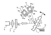
図1において、本波長可変光源装置は、例えば、波長選択デバイスとしての回折格子1と、複数(ここでは2個とする)の光源21,22と、光共振用反射部としてのハーフミラー3と、光結合部としてのレンズ4と、出力光路としての光ファイバ5と、を備えて構成される。
回折格子1は、例えば、基板の表面に等間隔dの溝を刻み、その凹凸面に金属膜等を蒸着した、一般的な反射型の回折格子である。この回折格子1は、後述する光源21,22およびハーフミラー3で形成される光共振器構成の中間に配置され、各光源21,22およびハーフミラー3から送られてくる光を金属膜上の反射点Rで反射する。また、上記の回折格子1には駆動部1Aが設けられている。この駆動部1Aは、反射点Rを中心として回折格子1を回転させることが可能であり、その回転角度は後述するように発振波長に応じて設定される。駆動部1Aによる回折格子1の駆動は、例えばモータ制御によって回折格子1を機械的に回転させるなどの周知の駆動機構を適用することが可能である。このような駆動機構は、例えば単一波長の波長可変光源等において既に適用されている。
【0016】
各光源21,22は、例えば、利得媒体2Aおよびレンズ2Bをそれぞれ有する。利得媒体2Aは、一方の端面に反射防止膜2AARが形成され、他方の端面には反射部品としての高反射ミラー2AHRが形成されていて、媒体内を伝搬する光の増幅作用を施す構成をとり、反射防止膜2AARの形成された端面から出射する。この利得媒体2Aの具体例としては、半導体レーザチップ等の一般的な利得媒体を使用することが可能である。レンズ2Bは、利得媒体2Aから出射される光をコリメートして回折格子1の反射点Rに向けて送出する。なお、本実施形態では、各光源21,22が所定の位置にそれぞれ固定されていて、出射される光の軸方向は変化しないものとする。
【0017】
ハーフミラー3は、回折格子1に対向させて配置され、回折格子1の反射点Rで反射されて垂直に入射される光の一部を反射して、各光源21,22の高反射ミラー2AHRとの間でそれぞれ光共振器構成を形成する。このハーフミラー3を透過した光は、レンズ4を介して光ファイバ5のコア端面に集光される。
なお、上記のような構成の波長可変光源装置については、環境温度の変化による影響を低減するために、回折格子1、光源21,22、ハーフミラー3およびレンズ4の各光学部品を一体化して温度を一定に制御するようにしてもよい。また、環境湿度の変化による影響を低減するために、前記各光学部品を真空管等の中にパッケージするようにしてもよい。
【0018】
次に、第1実施形態の動作について説明する。まず、本波長可変光源装置の動作を理解する上で有用であると考えられるため、一般的な反射型の回折格子の基本機能について説明する。
反射型の回折格子は、図2に示すように、その回折格子面に入射する光の波長に応じて、当該光の反射角度が異なる。この反射角度については、一般に、回折格子の格子間隔をd、入射光の波長をλ、入射光と反射光の間のなす角度をθ、回折次数をm(正または負の整数)とすると、次の(1)式に示す関係が成立する。
【0019】
d×sinθ=m×λ (1)
本波長可変光源装置は、上記のような分光機能を有する回折格子を分光器としてではなく合波器として利用する。すなわち、本波長可変光源装置では、各光源21,22から出射される光が回折格子1の反射点Rで反射されてハーフミラー3に入射されるように光学系が構成され、ハーフミラー3に垂直に入射される光のみが、ハーフミラー3と各光源21,22の高反射ミラー2AHRとの間を往復して各光源21,22の利得媒体2Aでそれぞれ増幅されて発振するようになる。そして、発振した各々の光の一部がハーフミラー3を透過してレンズ4により光ファイバ5のコア端面に集光されることで、合波された2波の光が光ファイバ5から出力される。
【0020】
本波長可変光源装置から出力される光の波長、すなわち、各光源21,22に対応した発振波長は、各々の光源21,22の光出射角度と、回折格子1の配置角度とによって決まる。このため、本波長可変光源装置では、例えば、所望の発振波長から逆算することによって、各光源21,22の光出射角度および回折格子1の配置角度が初期値として求められ、その初期値に基づいて各々の構成部品が所要の位置に配置される。そして、ここでは回折格子1が駆動部1Aにより回転することによって、各発振波長が広帯域に亘って連続的に変化するようになる。
【0021】
ここで、本波長可変光源装置における発振波長に対応した回折格子1の角度調整について具体的に説明する。
まず、前述の(1)式に示した関係について、反射角度θをテーラ展開(マクローリン展開)して求めると、次の(2)式となる。ただし、回折次数mは1次とする。
【0022】

【0023】
【0024】
【0025】
d=(5001)-1×10-2=2×10⁻⁶
この格子間隔dを(3)式および(4)式に代入して、発振波長λ1が1490nmのときの角度θ1、発振波長λ1’が1390nmのときの角度θ1’をそれぞれ求めると、θ1=48.159°およびθ1’=44.027°になる。従って、上記のような設定条件では、回折格子の角度を4.132°(=48.159°−48.159°)だけ変化させることによって、発振波長を1490nmから1390nmに変化させることが可能になる。
【0026】
なお、上記の具体例では回折次数mが1次の場合について説明した。回折次数が2次以上の高次の場合については、1次の回折光に対して波長が大きく離れるため、高次の回折光が1次の回折光に与える影響は殆どないものと考えられる。ただし、高次の回折光の影響を考慮する必要がある場合には、例えば、高次の回折光を遮断することが可能な光フィルタをハーフミラー3に適用するなどの措置を施すようにしてもよい。
【0027】
また、上記の具体例では1つの光源21についてのみ説明したが、他の光源22についても回折格子1の回転に伴って発振波長が変化する。本実施形態の構成では、各光源21,22の光出射角度が固定されているので、例えば図3(A)(B)に示すように、光源21に対応した発振波長λ1と、光源22に対応した発振波長λ2とは、回折格子1の回転に伴って一定の波長間隔A(=λ2−λ1=λ2’−λ1’)を保ちながら発振波長λ1’,λ2’にシフト(波長変化)することになる。
【0028】
なお、図3(A)は、シフト後の発振波長λ1’が、シフト前の発振波長λ2を超えない場合、すなわち、上記一定の波長間隔Aが、各々の発振波長のシフト量Δλ(=λ1’−λ1=λ2’−λ2)よりも広い場合を示している。一方、図3(B)は、シフト後の発振波長λ1’が、シフト前の発振波長λ2を超える場合、すなわち、一定の波長間隔A’が、各々の発振波長のシフト量よりも狭い場合を示している。
【0029】
ここで、本波長可変光源装置から出力される光パワーの高出力化について簡単に説明する。
光出力パワーの高出力化を図るためには、各光源21,22自体の高利得化と、各光源21,22の利得媒体2Aの出力端から光ファイバ5の集光位置までの光学系の低損失化とが必要になる。前者については、例えば公知の高出力型半導体レーザ等を各光源21,22に適用することが有効である。また、後者については、回折格子1の反射低損失化やレンズ結合効率の最適化、ハーフミラー3から高反射ミラー2AHRまでの間の共振長の短尺化などを図ることが効果的である。具体的に、周知の波長可変光源装置の光学系の損失は一般的に3〜7dB程度と考えられるので、本波長可変光源装置の光学系の損失を例えば7dBとしても、現在実用化されている高出力型半導体レーザに用いられているチップ(例えば、チップ出力700mW)を本波長可変光源装置の利得媒体2Aに適用した場合を想定すると、光ファイバ5の集光位置での光パワーは、1発振波長当たり140mW程度になる。従って、複数の光源を用いて構成される本波長可変光源装置の出力光は、例えば、一般的なラマン増幅器の励起光として適用可能なパワーレベルを満足することができる。
【0030】
上記のように第1実施形態の波長可変光源装置によれば、駆動部1Aにより回折格子1を回転させて配置角度を変化させ、ハーフミラー3に垂直に入射する複数の光の波長を変化させるようにしたことで、波長可変光源と合波器と個別に組み合わせた従来構成に対して、それらの機能を一体化させた構成を容易に実現することができ、かつ、各光源21,22に対応した発振波長λ1,λ2を回折格子1の回転角度の設定精度に応じて広帯域に亘り連続的に変化させることが可能になる。また、各発振波長λ1,λ2の可変波長範囲は、回折格子1を用いたことによって、従来の光源の温度制御などによる場合に比べて極めて広くなり、その上限値は、現在の技術では利得媒体2Aの利得帯域(例えば、100nm程度)に応じて決まることになる。さらに、本波長可変光源装置から出力される光のパワーについても、各光源21,22の利得媒体2Aにおける利得を例えば駆動電流の注入量の調整等を行うことにより個別かつ連続的に制御することが可能である。
【0031】
なお、上記の第1実施形態では、波長選択デバイスとしての反射型の回折格子を使用する場合を示したが、本発明はこれに限られるものではなく、透過型の回折格子やその他の波長選択性を有する公知のデバイスを適用することが可能である。図4には、透過型の回折格子を用いて構成した波長可変光源装置の一例を示しておく。
【0032】
また、上記の第1実施形態では、2つの光源21,22を用いて発振波長数を2波に設定した場合について説明したが、本発明はこれに限らず、光源の設置数を増やすことで発振波長数を任意に設定することが可能である。また、発振波長数が予め想定していた数よりも増える場合を考慮して、本波長可変光源装置の光源部分をユニット化するようにして増設に容易に対応できる構成を採用してもよい。具体的には、例えば図5に示すように、上記の第1実施形態の構成を基本光源ユニットとし、その基本光源ユニットに対して増設光源ユニットを組み合わせていくような構成などが可能である。
【0033】
ここで、本発明の波長可変光源装置における発振波長数の設定に関する制約ついて説明しておく。
本波長可変光源装置の発振波長数の上限は、各発振波長およびそれらの間隔と、回折格子の格子間隔dと、各光源の大きさおよびその配置(回折格子との距離)との関係から決まる。具体的には、発振波長間隔が狭くなるほど、各光源同士の回折格子に対する光出射角度の差が狭くなるので、各々の光源の大きさとその配置の仕方によって物理的な限界が生じてくる。
【0034】
例えば、1.4μm帯InGaAsP/InP系の半導体レーザチップの大きさは、一般に、幅が250〜300μm、長さが800〜1000μm、高さが100〜150μmである。このような大きさの半導体レーザチップを利得媒体として用いた光源21,22間の最小幅を300μmとし、回折格子1の溝の間隔が1cmに6500本の割合であって(格子間隔d=1.54×10-6m)、発振波長が1430nmと1460nmに設定される場合を想定すると、各光源21,22の配置としては、回折格子1の反射点Rに向けた各々の光源の光出射角度の差が3.27°(71.65°−68.38°)となるようにする必要がある。この場合、各光源と回折格子との距離は、5.26mm(=300μm/sin3.27°)程度で済むことになる。しかしながら、例えば発振波長が1428nmと1430nmに設定される場合には、各光源の光出射角度の差が0.2°(68.18°−68.38°)という小さな値となるように、各々の光源21,22を配置する必要があり、各光源21,22と回折格子1との距離は約86mm(=300μm/sin0.2°)となってしまう。この場合、光の共振長が長くなるため損失の増大や本波長可変光源(複数の光源および合波器)自身のサイズの大型化等を招くことになる。従って、本波長可変光源装置における発振波長間隔としては、数nm以上を確保するようにするのが望ましい。
【0035】
なお、上記の検討では各光源21,22を同一平面上に配置することを前提として考えた。しかし、回折格子1の反射点Rとしては、ハーフミラー3を透過した光が光ファイバ5のコアに光結合可能な所要の領域の許容度によっては、その反射点Rの領域に応じて各光源21,22を上記の同一平面上から離して立体的に配置することも可能である。
【0036】
また、狭い発振波長間隔に対応して光の共振長を比較的長く設定しなければならない場合には光のスペクトル線幅が細くなるため、必要に応じて、光源の駆動電流に1MHz程度の変調をかけてスペクトル線幅を増加させるようにすることも有効である。
次に、本発明による波長可変光源装置の第2実施形態について説明する。
【0037】
図6は、第2実施形態の波長可変光源装置の構成を示す平面図である。
図6において、本波長可変光源装置は、前述の図1に示した第1実施形態の構成について、光源21を基準光源として、光源22に駆動部2Cを設けたものである。なお、上記以外の他の部分の構成は第1実施形態の場合と同様である。
駆動部2Cは、例えば、図示しない可動ステージ等に光源22を設置し、その可動ステージをモータ制御などによって移動させることで、光源22の光出射角度を変化させるものである。この駆動部2Cによる光源22の移動は、具体的には、光源22の光出射面が回折格子1の反射点Rを中心とした円弧a上に位置するようにして行われる。
【0038】
上記のような構成の波長可変光源装置では、回折格子1の配置角度に加えて光源22の光出射角度も可変になるため、光源21に対応した発振波長λ1に対する光源22に対応した発振波長λ2の関係、すなわち、発振波長λ1,λ2の波長間隔についても変化させることが可能になる。例えば、図7(A)(B)に示すように、発振波長を変化させる前における波長λ1,λ2の間隔Bに対して、変化させた後における波長λ1’,λ2’の間隔B’を相違させることができるようになる。なお、図7(A)は、変化後の発振波長λ1’が変化前の発振波長λ2を超えない場合を示し、図7(B)は、変化後の発振波長λ1’が変化前の発振波長λ2を超える場合を示している。
【0039】
このように第2実施形態の波長可変光源装置によれば、光源22の光出射角度を可変にしたことで、発振波長の間隔についても連続的に変化させることが可能になる。
なお、上記の第2実施形態では、光源21を基準光源として光源22に駆動部2Cを設けるようにしたが、光源22を基準光源として光源21に駆動部2Cを設けるようにしてもよい。また、3つ以上の光源を用いる場合には、それらの光源のうちの1つを基準光源として、残りの光源のうちの少なくとも1つに駆動部2Cを設けるようにすることも可能である。
【0040】
次に、本発明による波長可変光源装置の第3実施形態について説明する。
図8は、第3実施形態の波長可変光源装置の構成を示す平面図である。
図8において、本波長可変光源装置は、例えば、前述の図6に示した第2実施形態の構成について、実際の出力光に基づいて各駆動部1A,2Cをフィードバック制御するためのモニタ部6および制御部7を設けるようにしたものである。
【0041】
モニタ部6は、光ファイバ5のコア端面に集光された光の一部を分岐し、その分岐光に含まれる各発振光の波長をモニタする。制御部7は、モニタ部6でモニタされた各発振波長に基づいて、実際に出力される光の発振波長が所望の値に一致するように、各駆動部1A,2Cの駆動状態を調整して回折格子1の配置角度、さらには光源22の光出射角度をフィードバック制御する。この制御部7には、回折格子1の反射点Rに対する各光源21,22の配置などの光学系に関する情報が予め設定されていて、その設定情報を基にして、モニタ部6でモニタされた実際の発振波長と所望の発振波長とのずれを補正するための回折格子1の配置角度および光源22の光出射角度の各制御量が演算される。
【0042】
このような波長可変光源装置によれば、実際に合波されて出力される光の発振波長に応じて回折格子1の配置角度と光源22の光出射角度とをフィードバック制御するようにしたことで、例えば環境変化や経時変化等による発振波長の変動を補正することができるため、所望の発振波長の光を安定して出力することが可能である。
【0043】
なお、上記の第3実施形態では、前述した第2実施形態についてフィードバック制御を行うようにしたが、上述した第1実施形態についても同様にして応用することができる。この場合、実際に出力される各発振光のうちの基準となる1つの発振光の波長をモニタすることで、回折格子1の配置角度をフィードバック制御することが可能である。
【0044】
また、実際の発振波長のモニタ結果に応じて、回折格子1の配置角度および光源22の光出射角度の各制御量を制御部7で演算するようにしたが、想定される発振波長に対する各々の制御量をデータベース化しておき、モニタ結果に応じてデータベースを参照して回折格子1の配置角度および光源22の光出射角度を制御するようにしてもよい。
【0045】
次に、本発明にかかる波長可変光源装置を用いた光増幅器の実施形態について説明する。
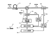
図9は、本発明の波長可変光源装置を励起光源として用いたラマン増幅器の構成例を示すブロック図である。
図9に示すラマン増幅器10は、例えば、光増幅媒体としての光伝送路11に励起光Pを供給するための波長可変光源装置12および光サーキュレータ13と、その励起光Pの供給状態をモニタするための分岐部14および励起光モニタ部15と、光伝送路11を伝搬してラマン増幅されたWDM信号光Sをモニタするための分岐部16および信号光モニタ部17と、信号光モニタ部17のモニタ結果に基づいて、WDM信号光の伝送品質に関する情報(伝送品質情報)や本ラマン増幅器10の接続されるシステムの運用状況に関する情報(システム運用情報)を生成して管理するシステム管理部18と、信号光モニタ部17のモニタ結果およびシステム管理部18の管理情報に応じて、波長可変光源装置12の駆動部を制御する励起光管理部19と、を備えて構成される。
【0046】
なお、このラマン増幅器10の構成は、本出願人の先願である特願2002−10298号に記載したラマン増幅器の構成と基本的に同様であり、本発明にかかる波長可変光源装置12を励起光源および合波器として用いた部分が先願発明とは相違するものである。
波長可変光源装置12は、上述した第1実施形態または第2実施形態による波長可変光源装置を用いたものであり、ここでは例えば光源の設置数を一般化してN個とし、波長の異なるN波の励起光P0〜PNを合波して出力する。この波長可変光源装置12は、上述したように回折格子1の配置角度さらには各光源の光出射角度を変化させることにより、各励起光P0〜PNの波長λ0〜λNを広帯域に亘って連続的に変化させることが可能であると共に、各々の光源内の利得媒体2Aにおける利得を例えば駆動電流の注入量の調整等を行って変化させることにより各励起光P0〜PNのパワーを変化させることが可能である。
【0047】
光サーキュレータ13は、波長可変光源装置12から出力され分岐部14を通過した励起光Pを光伝送路11(増幅媒体)に供給するためのものであって、ここでは、励起光Pの伝搬方向がWDM信号光Sの伝搬方向に対して逆向きとなるように、励起光Pを光伝送路11に与える。また、光サーキュレータ13は、光伝送路11を伝搬してラマン増幅されたWDM信号光Sを通過させて出力側の光路に伝える。
【0048】
なお、ここでは光サーキュレータ13を用いて光伝送路11に励起光を供給するようにしたが、光サーキュレータ13に代えてWDMカプラ(融着型)や合波干渉膜等を使用することも可能である。また、光伝送路11の具体例としては、高非線形ファイバまたはシリカ系ファイバ等とすることが可能である。
分岐部14は、波長可変光源装置12から出力される励起光Pの一部をモニタ光Pmとして分岐して励起光モニタ部15に出力する。励起光モニタ部15は、分岐部14からのモニタ光Pmを基に励起光Pのパワーおよびスペクトルを監視し、その結果を励起光管理部19に伝える。
【0049】
分岐部16は、光サーキュレータ13を通過したWDM信号光Sの一部をモニタ光Smとして分岐して信号光モニタ部17に出力する。信号光モニタ部17は、分岐部16からのモニタ光Smを基にラマン増幅されたWDM信号光Sの出力状態を監視し、その結果をシステム管理部18に伝える。また、信号光モニタ部17は、分岐部16からのモニタ光Smを用いてWDM信号光Sに含まれる監視制御(Supervisory)信号を検出してシステム管理部18に伝える。
【0050】
システム管理部18は、信号光モニタ部17でモニタされた光SN比や出力レベル等を基に伝送品質情報を生成すると共に、信号光モニタ部17で検出された監視制御信号を基にシステム運用情報を生成して励起光管理部19に送る。なお、具体的な伝送品質情報としては、例えば、ラマン増幅されたWDM信号光Sの光SN比やチャネル間偏差、光パワーレベルなどを挙げることができる。また、具体的なシステム運用情報としては、例えば、WDM信号光Sの波長帯域や信号光数、光伝送路への信号光入力レベル、光伝送路の種類などを挙げることができる。
【0051】
励起光管理部19は、システム管理部18からの伝送品質情報およびシステム運用情報に応じて、運用中のサービスに影響を与えることなく運用状況の変化に対応可能なラマン増幅を実現させるための励起光の最適な供給状態を算出する。そして、励起光管理部19は、その算出結果を目標値(初期値)に設定して、波長可変光源装置12で発生する励起光の波長およびパワーをそれぞれ制御する。また、励起光管理部19は、励起光モニタ部15からのモニタ結果に基づいて、実際に供給される励起光Pが上記の目標値に一致するように波長可変光源装置12のフィードバック制御を実行する。
【0052】
次に、上記のようなラマン増幅器10の動作について説明する。
本ラマン増幅器10では、基本的に、励起光管理部19によって波長およびパワーの制御された励起光Pが、光サーキュレータ13により光伝送路11に供給されてWDM信号光Sとは逆方向に光伝送路11内を伝搬する。そして、この励起光Pによるラマン効果によって光伝送路11を伝搬するWDM信号光Sが所要のレベルまで増幅され、そのラマン増幅されたWDM信号光Sが光サーキュレータ13を通過して出力側の光路に送られる。このWDM信号光Sには、例えば、低周波の強度変調や信号光とは別のチャネルの使用などにより監視制御信号が載せられていて、その監視制御信号が、ここでは分岐部16を介して信号光モニタ部17によって検出されてシステム管理部18に伝えられる。システム管理部18では、検出された監視制御信号に基づいて、前述したようなWDM信号光Sの波長帯域などの運用状況が判断されてシステム運用情報が生成される。
【0053】
そして、システム管理部18においてシステム運用状況の変化が判断されると、その変化に応じて、波長可変光源装置12から出力される励起光Pの供給状態の最適化が図られる。例えば、WDM信号光Sについて短波長側の信号光が増設されるような場合には、新たな波長帯域の信号光をラマン増幅するために励起光の波長を短波長側にシフトさせることが必要になる。具体的には、システム運用状況の変化として、WDM信号光Sの波長帯域が1530nm〜1600nmから1490nm〜1600nmに変更されるとき(いわゆるSバンドの増設)、波長可変光源装置12の例えば3つの光源21,22,23に対応した発振波長を変更前の1430nm,1450nm,1490nmから変更後の1395nm,1415nm,1455nmにそれぞれシフトさせる場合、波長可変光源装置1に用いられる回折格子の溝間隔が1cmに5000本であるとすると、回折格子の配置角度を1.437°変化させることによって、上記のような励起波長のシフトを実現することが可能になる。
【0054】
なお、上記の場合において、信号光の誘導ラマン散乱(SRS)効果により、長波長側の信号光は短波長側の信号光からエネルギーシフトを受けて光パワーが増加することが考えられ、励起波長をシフトさせる優先度として長波長側よりも短波長側を高く設定することが有効となる場合がある。このような場合には、回折格子の配置角度を変化させると共に、各光源の光出射角度を優先度に従い順に変化させるようにすることで、励起波長をシフトさせる順番までを制御することが可能になる。
【0055】
また例えば、光伝送路11の長さが変わるような場合には、光伝送路長が長い方が前述した信号光のSRS効果をより強く生じるため短波長側の信号光をより大きく増幅させる必要があり、光伝送路11の増長に応じて励起波長を短波長側にシフトさせることが必要になる。具体的に、システム運用状況の変化として、光伝送路11の増長により1スパンあたりの損失が20dBから25dBに変更されるとき、波長可変光源装置12の例えば3つの光源21,22,23に対応した発振波長を変更前の1430nm,1450nm,1490nmから変更後の1425nm,1445nm,1485nmにそれぞれシフトさせる場合、波長可変光源装置12に用いられる回折格子の溝間隔が1cmに5000本であるとすると、回折格子の配置角度を0.208°変化させることによって、上記のような励起波長のシフトを実現することが可能になる。
【0056】
さらに例えば、WDM信号光Sに含まれる信号光数が大きく変化する場合にも、その変化に応じた励起光の制御が必要である。具体的に、システム運用状況の変化として、信号光数がフルチャネルの88チャネルから最短波長および最長波長の2チャネルに変更されるとき、波長可変光源装置12の例えば3つの光源21,22,23に対応した発振波長を変更前の1430nm,1450nm,1490nmから変更後の1425nm,1495nmにそれぞれシフトさせる場合、まず、光源22を駆動停止させて波長1450nmの励起光をオフとする。そして、波長可変光源装置12に用いられる回折格子の溝間隔が1cmに5000本であるとすると、回折格子の配置角度を0.205°変化させて光源21に対応した励起波長を1425nmにシフトさせた後に、光源23の光出射角度を−0.429°変化させて励起波長を1495nmにシフトさせるようにする。
【0057】
上記のようなシステム運用状況の変化に応じた励起波長の具体的な制御方法に関しては、前述した先願である特願2002−10298号に詳しく開示してあるので参照されたい。ここでは、先願で開示した制御方法の基本的な内容について図10のフローチャートに従い簡単に説明しておくことにする。
まず、図10のステップ1(図中S1で示し、以下同様とする)において、運用状況の変化を示すシステム運用情報がシステム管理部18から励起光管理部19に伝えられると、ステップ2では、運用状況の変化後における励起光Pの最適な供給状態が励起光管理部19において算出される。この最適な供給状態の算出は、例えば、励起光管理部19に予め登録設定されたデータベースを参照するなどして、変化後のシステム運用状況に対応した励起光Pの波長およびパワーの最適値が求められる。
【0058】
さらに、ステップ3では、励起光管理部19において、運用状況の変化前の励起光Pの供給状態からステップ2で算出した変化後の励起光Pの供給状態への移行方法が判断され、運用中のサービスに影響を与えることなく所要の伝送品質を保持し得るような励起光Pの波長およびパワーの変更手順が決定される。
そして、ステップ4では、励起光管理部19によって、ステップ3で決定した変更手順に従い、運用状況の時間的な変化と同期をとりながら、励起光Pの供給状態がステップ2で算出した変化後の最適値に達するまで、波長可変光源装置12の動作が制御される。
【0059】
また、ステップ5においては、励起光モニタ部15のモニタ結果に応じて実際に供給されている励起光Pの状態が目標値に一致するように、波長可変光源装置12のフィードバック制御が行われる。さらにこれと同時に、信号光モニタ部17のモニタ結果を基にシステム管理部18で生成される伝送品質情報に応じて、実際にラマン増幅されたWDM信号光Sの伝送品質が良好に保たれるように励起光Pの供給状態が微調整される。
【0060】
上記のステップ3において決定される励起光Pの供給状態の変更手順については、第1段階として、変化前の励起光Pの波長設定から変化後の励起光Pの波長設定への変更方法を判断し、第2段階として、運用中の各チャネル光の伝送品質の保持に配慮した励起光Pの波長およびパワーの変更手順を決定するのがよい。
上記の第1段階においては、例えば、変化前の各励起波長と、最適値として算出した変化後の各励起波長との差分を求め、その差分が小さな励起波長に対応させて光源の波長設定を変更するのが望ましい。ただし、求めた差分が励起光源の波長可変幅を超える場合には、新たな光源を立ち上げるものとする。
【0061】
上記の第2段階においては、基本的に、システム運用状況の時間的な変化に同期して、各励起光P1〜PNについての波長およびパワーの調整が同時進行で実施されるように、波長可変光源装置12の調整手順が決められるものとする。また、各励起光P1〜PNに対する調整の優先度を設定し、すなわち、伝送品質に与える影響が小さい励起光に対する調整の優先度を低くして、運用中の各チャネル光についての伝送品質の保持が図られるように変更手順が決められるのが望ましい。
【0062】
上記の優先度が高くなる条件としては、例えば、運用状況の変化前における励起光の波長が変化後の信号光の波長に一致するか若しくは近接するような場合に、当該励起光に対する制御の優先度を他の励起光よりも高く設定して、その励起光の波長が上記信号光の運用開始前にシフトされるようにすることが考えられる。また例えば、運用状況が変化していく過程にある信号光帯域についてのラマン利得を担う励起光に対する制御の優先度を他の励起光よりも高く設定することにより、運用状況の変化への対応がより確実に行われるようにすることも考えられる。
【0063】
このような優先度に従った励起光の調整を行うためには、例えば、優先度の設定と想定される調整方法に関する情報を予めデータベース化しておき、この情報を基に波長可変光源装置12の配置設定の変更手順を決定するようにする。上記の想定される調整方法としては、例えば、ある励起光の波長をシフトさせる場合、シフト前の波長の励起光が担っていた波長帯域のラマン利得が減少することになるので、そのシフト前の波長により近い波長の励起光のパワーを増加させるように調整を行うことが考えられる。また例えば、ある波長の励起光のパワーを増加させる場合、その波長により近い波長の励起光のパワーを減少させるようにしてもよい。
【0064】
上記のようなラマン増幅器10によれば、N波の発振波長を広帯域に亘って連続的に変化させることのできる波長可変光源装置12を励起光源として用いるようにしたことで、システムの運用状況がダイナミックに変化する場合でも、その変化に応じて各励起光P1〜PNの波長およびパワーが最適化されるため、運用中のサービスに影響を与えることなくラマン増幅の状態を変更することが可能である。これにより、広範な波長帯域に亘り運用されるWDM信号光に柔軟に対応できるラマン増幅器の実現が可能になる。
【0065】
なお、本発明の波長可変光源装置を励起光源として用いた光増幅器は、上記のような構成のラマン増幅器に限定されるものではなく、公知の構成のラマン増幅器に適用することができ、さらには、波長の異なる複数の励起光を用いる各種の光増幅器とすることも可能である。
以上、本明細書で開示した主な発明について以下にまとめる。
【0066】
(付記1) 複数の波長可変光を合波して出力する波長可変光源装置であって、
入射光の波長に応じて出射光の伝搬方向が変化する波長選択デバイスと、
光を増幅する利得媒体および該利得媒体の一端に入射され他端から出射される光を反射して他端に戻す反射部品をそれぞれ有し、前記利得媒体内を往復して増幅された光を前記波長選択デバイスの所定位置に向けて互いに異なる角度で出射する複数の光源部と、
前記波長選択デバイスからの出射光が入射する光入射面を有し、該光入射面に対して垂直に入射する光の一部を反射することにより、前記各光源部の反射部品との間でそれぞれ光共振器構成を形成して発振光を生成する光共振用反射部と、
前記光共振用反射部を透過した発振光を出力光路に結合させる光結合部と、
前記光共振用反射部に対する前記波長選択デバイスの配置角度を、前記各光源部からの光が前記波長選択デバイスに照射される点を中心にして変化させる波長選択デバイス駆動部と、
を備えて構成されたことを特徴とする波長可変光源装置。
【0067】
(付記2) 付記1に記載の波長可変光源装置であって、
前記複数の光源部のうちの少なくとも1つ以上の光源部について、前記波長選択デバイスの所定位置に向けた光の出射角度を変化させる光源駆動部を備えたことを特徴とする波長可変光源装置。
【0068】
(付記3) 付記1に記載の波長可変光源装置であって、
前記出力光路に結合された発振光の波長を検出するモニタ部と、
前記モニタ部で検出される波長に応じて、前記波長選択デバイス駆動部を制御する制御部とを備えたことを特徴とする波長可変光源装置。
【0069】
(付記4) 付記2に記載の波長可変光源装置であって、
前記出力光路に集光された発振光の波長を検出するモニタ部と、
前記モニタ部で検出される長に応じて、前記波長選択デバイス駆動部および光源駆動部の少なくとも一方を制御する制御部とを備えたことを特徴とする波長可変光源装置。
【0070】
(付記5) 付記1に記載の波長可変光源装置であって、
前記波長選択デバイスは、回折格子であることを特徴とする波長可変光源装置。
【0071】
(付記6) 付記5に記載の波長可変光源装置であって、
前記回折格子は、反射型の構成であることを特徴とする波長可変光源装置。
【0072】
(付記7) 付記5に記載の波長可変光源装置であって、
前記回折格子は、透過型の構成であることを特徴とする波長可変光源装置。
【0073】
(付記8) 付記1に記載の波長可変光源装置であって、
前記各光源部は、半導体レーザーを含むことを特徴とする波長可変光源装置。
【0074】
(付記9) 付記1に記載の波長可変光源装置を励起光源として用いたことを特徴とする光増幅器。
【0075】
(付記10) 付記9に記載の光増幅器であって、
前記波長可変光源装置から出力される励起光を光伝送路上のシリカ系ファイバを用いた増幅媒体に供給し、該増幅媒体を伝搬する信号光をラマン増幅することを特徴とする光増幅器。
【0076】
(付記11) 付記10に記載の光増幅器であって、信号光の伝送に関する運用状況を示す情報を基に、当該運用状況の時間的な変化に同期して、前記波長可変光源装置による励起光の供給状態を制御することを特徴とする光増幅器。
【0077】
【発明の効果】
以上説明したように本発明の波長可変光源装置によれば、波長選択デバイスの配置角度や各光源部の光出射角度を変化させて光共振用反射部の光入射面に垂直に入射する光の波長を可変にしたことで、波長を広帯域に亘って連続的に変化させることが可能な複数の発振光を合波した光が容易に得られ、それをラマン増幅用の励起光として光伝送路に送出することにより、広範な波長帯域で運用される信号光のラマン増幅を単一構成の励起光源によって実現することが可能になる。また、光伝送路に用いられるファイバの種類および光伝送路におけるラマン増幅帯域に応じた波長間隔・配置の発振光が出力光路に結合されるように、各光源部の配置が決められることで、波長選択デバイスの配置角度が変化しても励起光の波長間隔は一定となるため、ラマン増幅帯域の形を変えること無く当該増幅帯域をシフトすることができる。
【図面の簡単な説明】
【図1】本発明による波長可変光源装置の第1実施形態の構成を示す平面図である。
【図2】一般的な反射型の回折格子の基本機能を説明するための図である。
【図3】上記の第1実施形態における発振波長の変化の一例を示す図であって、(A)は各発振波長の波長間隔が各々のシフト量よりも広い場合、(B)は各発振波長の波長間隔が各々のシフト量よりも狭い場合を示す図である。
【図4】上記の第1実施形態に関連して、透過型の回折格子を用いた波長可変光源装置の一例を示す構成図である。
【図5】上記の第1実施形態に関連して、光源部分をユニット化して増設にも対応可能とした一例を示す構成図である。
【図6】本発明による波長可変光源装置の第2実施形態の構成を示す平面図である。
【図7】上記の第2実施形態における発振波長の変化の一例を示す図であって、(A)は変化後の発振波長λ1’が変化前の他の発振波長λ2を超えない場合、(B)は変化後の発振波長λ1’が変化前の他の発振波長λ2を超える場合を示す図である。
【図8】本発明による波長可変光源装置の第3実施形態の構成を示す平面図である。
【図9】本発明の波長可変光源装置を励起光源として用いたラマン増幅器の構成を示すブロック図である。
【図10】図9のラマン増幅器について、システム運用状況の変化に応じた励起波長の具体的な制御方法の一例を説明するためのフローチャートである。
【符号の説明】
1 回折格子
1A 駆動部(回折格子用)
21,22 光源
2A 利得媒体
2AAR 反射防止膜
2AHR 高反射ミラー
2B,4 レンズ
2C 駆動部(光源用)
3 ハーフミラー
5 光ファイバ
10 ラマン増幅器
11 光伝送路
12 波長可変光源装置
13 光サーキュレータ
14,16 分岐部
15 励起光モニタ部
17 信号光モニタ部
18 システム管理部
19 励起光管理部
d 格子間隔
P 励起光
S 信号光[0001]
BACKGROUND OF THE INVENTION
The present invention relates to a wavelength tunable light source device used in various optical communication systems and an optical amplifier using the same, and more particularly to a wavelength tunable light source device capable of continuously changing the wavelengths of a plurality of oscillation lights over a wide band. The present invention also relates to an optical amplifier that uses the same to form a pumping system.
[0002]
[Prior art]
For example, in a wavelength division multiplexing (WDM) optical fiber communication system, there is an optical amplification technique as one of key technologies, and an erbium (Er) doped fiber optical amplifier (EDFA) or the like is generally used in a conventional system. In addition, with the recent spread of the Internet, network demand has grown rapidly, and there has been a demand for higher capacity and longer distances for optical fiber communication systems. Raman amplifiers have begun to be put into practical use as an optical amplification technique. By using this Raman amplifier and EDFA together, it becomes possible to realize higher quality transmission characteristics than when EDFA is used alone. Therefore, it is expected to become an essential technology in long-distance transmission systems. .
[0003]
The Raman amplifier includes a distributed constant type and a concentrated type. In the distributed constant type, pump light is introduced into a transmission line (for example, silica-based fiber, etc.) of an optical fiber communication system, optical signals propagating through the transmission line are distributed in Raman, and a part of transmission loss is compensated. It is a form to do. On the other hand, the concentrated type is a form in which optical signals are efficiently Raman-amplified by intensively introducing pumping light into a medium having high nonlinearity (for example, silica-based fiber having a small effective area). Such Raman amplification is known to have a gain peak at a frequency 13.2 THz lower than the frequency of the pumping light when the medium is a silica-based fiber. For this reason, the Raman amplifier has a feature that an optical signal having an arbitrary wavelength can be amplified according to the wavelength of the excitation light source. In addition, a wide range of Raman amplification bands can be realized by preparing a plurality of excitation light sources having different wavelengths and combining the excitation lights and supplying them to the amplification medium. Such a Raman amplifier has begun to be put into practical use.
[0004]
For the pumping system parts of the Raman amplifier as described above, a semiconductor laser or the like is generally used as a pumping light source, and an interference film, a fusion coupler, or a Mach-Zehnder type light is used as a multiplexer that combines pumping light of each wavelength. A filter or the like is used. For Raman amplifiers using such pumping system components, it is a matter of course when the pumping wavelength is made variable in a wide band (for example, several nm or more) in order to enable amplification of an optical signal in an arbitrary wavelength band. However, it is necessary to make the multiplexing wavelength characteristic of the multiplexer variable according to the change of the excitation wavelength.
[0005]
As conventional multiplexers having variable wavelength characteristics, there are known ones disclosed in, for example, Japanese Patent Application Laid-Open No. 56-113102 and Japanese Utility Model Application Laid-Open No. 60-104804. These conventional multiplexers use an interference film. Specifically, films having different transmission characteristics are deposited on the same substrate, and a predetermined film is selected by moving the substrate. It is.
[0006]
[Problems to be solved by the invention]
However, since the conventional multiplexer as described above cannot continuously change the combined wavelength characteristic at an arbitrary wavelength, the Raman amplifier in which the excitation wavelength is made variable by using conventional excitation system components. However, it is actually difficult to make the wavelengths of the plurality of excitation lights continuously variable over a wide band.
[0007]
In the next-generation optical network system, for example, it is assumed that the operation status of the system such as a signal band, the number of signals, a signal input level, and a transmission path type dynamically changes. Therefore, for a Raman amplifier applied to such a system, in order to keep the transmission quality of each signal channel good, the excitation light spectrum (specifically, depending on the operation status of the dynamically changing system) It is required to optimize the number of peak wavelengths, center wavelength, bandwidth, pumping light power, etc.) with high accuracy.
[0008]
Regarding the excitation wavelength control of the Raman amplifier, for example, Japanese Patent Application Laid-Open No. 2001-235772 also describes that the excitation wavelength is variable. However, the means for changing the excitation wavelength in this known technique is to change the excitation wavelength by adjusting the operating temperature of the excitation light source, and the variable width is specifically a narrow band of about 0.1 nm / ° C. Therefore, as described above, it is difficult to continuously vary the excitation wavelength over a wide band of, for example, several nanometers or more, and it is difficult to flexibly cope with a dynamic change in the system operation status.
[0009]
The present invention has been made by paying attention to the above points, and an object thereof is to realize a wavelength tunable light source device capable of continuously changing a plurality of oscillation wavelengths over a wide band. In addition, by configuring a pumping system using the above-described wavelength tunable light source device, an optical amplifier capable of supporting a wide system operating range with a single optical amplifier and smoothly responding to changes in the operating status of the system The purpose is to provide.
[0010]
[Means for Solving the Problems]
In order to achieve the above object, a wavelength tunable light source device of the present invention is provided.,A wavelength selection device that changes the propagation direction of outgoing light according to the wavelength of incident light, a gain medium that amplifies the light, and light that enters one end of the gain medium and exits from the other end and reflects it back to the other end A plurality of light source units each having a reflective component and emitting light amplified by reciprocating in the gain medium toward a predetermined position of the wavelength selection device and light emitted from the wavelength selection device are incident It has a light incident surface and reflects a part of the light incident perpendicularly to the light incident surface, thereby forming an optical resonator configuration with each reflective component of each light source unit to generate oscillation light. Transmitted through the optical resonance reflector and the optical resonance reflectorpluralOscillation light is coupled to the output optical pathAnd output to the optical transmission line connected to the output optical path.A wavelength selection device driving unit that changes an arrangement angle of the wavelength selection device with respect to the reflection unit for optical resonance, centering on a point where light from each light source unit is irradiated to the wavelength selection device, WithThe arrangement of the plurality of light source units is such that the interval and arrangement of the wavelengths of the oscillation light by the plurality of light source units and the optical resonance reflecting unit is the type of fiber used in the optical transmission line and the Raman amplification in the optical transmission line It is characterized by having a wavelength interval / arrangement corresponding to the band.
[0011]
In the wavelength tunable light source device having such a configuration, the light emitted from each light source unit is incident on the predetermined position of the wavelength selection device at a different angle and is emitted toward the light incident surface of the optical resonance reflection unit. Only light that is perpendicularly incident on the light incident surface of the light source is reflected and oscillates by resonating with the reflective component of each light source. The wavelength of each light oscillated by the optical resonator configuration between the reflection part for optical resonance and the reflection component of each light source part changes the arrangement angle of the wavelength selection device with respect to the reflection part for optical resonance by the wavelength selection device driver. To make it variable. As a result, the light transmitted through the optical resonance reflection section and guided to the output optical path via the optical coupling section is combined with a plurality of oscillation lights whose wavelengths can be continuously changed over a wide band. NaIt is sent to the optical transmission line as excitation light. The wavelength interval / arrangement of the light transmitted to the optical transmission line depends on the type of fiber used in the optical transmission line and the Raman amplification band in the optical transmission line according to the arrangement of each light source unit. Even if the arrangement angle of the selection device is changed, the wavelength interval of the excitation light becomes constant.
[0012]
Also aboveTunable wavelengthThe light source device may include a light source driving unit that changes an emission angle of light toward a predetermined position of the wavelength selection device with respect to at least one of the plurality of light source units. As a result, the oscillation wavelength interval corresponding to each light source section is also variable. In addition, the aboveTunable wavelengthFor the light source device, a monitor unit that detects the wavelength of the oscillation light coupled to the output optical path, and a control unit that controls the wavelength selection device driving unit or the light source driving unit according to the wavelength detected by the monitoring unit. You may make it prepare. In such a configuration, fluctuations in the oscillation wavelength due to environmental changes and the like are corrected by feedback control of the arrangement angle of the wavelength selection device and the light emission angle of each light source unit according to the oscillation wavelength of the combined light actually output from the output optical path. As a result, light having a desired oscillation wavelength can be output stably.
In addition, as a specific configuration of the above-described wavelength tunable light source device, the wavelength selection device may be a diffraction grating, and the diffraction grating may be a reflection type or a transmission type. Each light source unit may include a semiconductor laser.
[0013]
Wavelength tunable light source device of the present invention as described aboveAn optical amplifier using as an excitation light sourceSpecifically, the pumping light output from the wavelength tunable light source device is supplied to an amplifying medium using a silica-based fiber on the optical transmission line, and an optical amplifier that Raman-amplifies signal light propagating through the amplifying medium is provided. Is possible. The optical amplifier controls the supply state of the pumping light by the wavelength tunable light source device in synchronization with the temporal change of the operation status based on the information indicating the operation status regarding the transmission of the signal light. Good. According to such an optical amplifier, since the wavelengths of a plurality of pump lights can be continuously changed over a wide band, amplification of signal light operated in a wide wavelength band can be performed by a pump light source having a single configuration. Can be realized.
[0014]
DETAILED DESCRIPTION OF THE INVENTION
Hereinafter, embodiments of the present invention will be described with reference to the drawings. In the drawings, the same components are denoted by the same reference numerals, and the description thereof is omitted.
FIG. 1 is a plan view showing the configuration of a first embodiment of a wavelength tunable light source device according to the present invention.
[0015]
In FIG. 1, the variable wavelength light source device includes, for example, a
The
[0016]
Each
[0017]
The
In addition, in the wavelength tunable light source device having the above configuration, the
[0018]
Next, the operation of the first embodiment will be described. First, since it is considered useful for understanding the operation of the variable wavelength light source device, the basic function of a general reflection type diffraction grating will be described.
As shown in FIG. 2, the reflection type diffraction grating has different reflection angles of light according to the wavelength of light incident on the diffraction grating surface. Regarding the reflection angle, generally, when the grating interval of the diffraction grating is d, the wavelength of incident light is λ, the angle formed between the incident light and the reflected light is θ, and the diffraction order is m (positive or negative integer), The relationship shown in the following equation (1) is established.
[0019]
d × sin θ = m × λ (1)
This wavelength tunable light source device uses a diffraction grating having the above-described spectral function as a multiplexer, not as a spectrometer. That is, in this variable wavelength light source device, each
[0020]
The wavelength of light output from the variable wavelength light source device, that is, each
[0021]
Here, the angle adjustment of the
First, regarding the relationship shown in the above equation (1), when the reflection angle θ is obtained by Taylor expansion (Maclaurin expansion), the following equation (2) is obtained. However, the diffraction order m is the first order.
[0022]
[0023]
[0024]
[0025]
d = (5001)-1× 10-2= 2 × 10⁻⁶
By substituting the lattice spacing d into the equations (3) and (4), the angle θ1 when the oscillation wavelength λ1 is 1490 nm and the angle θ1 ′ when the oscillation wavelength λ1 ′ is 1390 nm are obtained, respectively, θ1 = 48 .159 ° and θ1 ′ = 44.027 °. Therefore, under the setting conditions as described above, the oscillation wavelength can be changed from 1490 nm to 1390 nm by changing the angle of the diffraction grating by 4.132 ° (= 48.159 ° −48.159 °). Become.
[0026]
In the above specific example, the case where the diffraction order m is the first order has been described. When the diffraction order is higher than the second order, the wavelength is far away from the first order diffracted light. Therefore, it is considered that the higher order diffracted light has little influence on the first order diffracted light. However, when it is necessary to consider the influence of higher-order diffracted light, for example, measures such as applying an optical filter capable of blocking higher-order diffracted light to the
[0027]
In the above specific example, one
[0028]
FIG. 3A shows a case where the oscillation wavelength λ1 ′ after the shift does not exceed the oscillation wavelength λ2 before the shift, that is, the above-mentioned constant wavelength interval A is the amount of shift Δλ (= λ1) It shows a case wider than '−λ1 = λ2′−λ2). On the other hand, FIG. 3B shows the case where the oscillation wavelength λ1 ′ after the shift exceeds the oscillation wavelength λ2 before the shift, that is, the case where the constant wavelength interval A ′ is narrower than the shift amount of each oscillation wavelength. Show.
[0029]
Here, a brief description will be given of increasing the optical power output from the variable wavelength light source device.
In order to increase the optical output power, each
[0030]
As described above, according to the wavelength tunable light source device of the first embodiment, the
[0031]
In the first embodiment, the case where the reflection type diffraction grating is used as the wavelength selection device has been shown. However, the present invention is not limited to this, and the transmission type diffraction grating and other wavelength selection devices are used. It is possible to apply a known device having characteristics. FIG. 4 shows an example of a wavelength tunable light source device configured using a transmissive diffraction grating.
[0032]
In the first embodiment, two
[0033]
Here, the restrictions regarding the setting of the number of oscillation wavelengths in the wavelength tunable light source device of the present invention will be described.
The upper limit of the number of oscillation wavelengths of the wavelength tunable light source device is determined by the relationship between the oscillation wavelengths and their intervals, the grating interval d of the diffraction grating, the size of each light source and its arrangement (distance to the diffraction grating). . Specifically, the narrower the oscillation wavelength interval, the narrower the difference in the light emission angle with respect to the diffraction grating of each light source, so that there is a physical limit depending on the size of each light source and the manner in which it is arranged.
[0034]
For example, the size of a 1.4 μm band InGaAsP / InP semiconductor laser chip is generally 250 to 300 μm in width, 800 to 1000 μm in length, and 100 to 150 μm in height.
[0035]
In the above examination, each
[0036]
In addition, when the resonance length of light has to be set relatively long corresponding to a narrow oscillation wavelength interval, the spectral line width of light becomes narrow. Therefore, if necessary, the light source drive current is modulated by about 1 MHz. It is also effective to increase the spectral line width by applying.
Next, a second embodiment of the variable wavelength light source device according to the present invention will be described.
[0037]
FIG. 6 is a plan view showing the configuration of the wavelength tunable light source device of the second embodiment.
In FIG. 6, the wavelength tunable light source device includes a
For example, the
[0038]
In the variable wavelength light source device configured as described above, in addition to the arrangement angle of the
[0039]
Thus, according to the wavelength tunable light source device of the second embodiment, the
In the second embodiment, the
[0040]
Next, a third embodiment of the variable wavelength light source device according to the present invention will be described.
FIG. 8 is a plan view showing the configuration of the variable wavelength light source device of the third embodiment.
In FIG. 8, the wavelength tunable light source device includes, for example, a
[0041]
The
[0042]
According to such a wavelength tunable light source device, the arrangement angle of the
[0043]
In the third embodiment, the feedback control is performed for the second embodiment described above. However, the first embodiment can be applied in the same manner. In this case, it is possible to feedback control the arrangement angle of the
[0044]
Further, the arrangement angle of the
[0045]
Next, an embodiment of an optical amplifier using the wavelength tunable light source device according to the present invention will be described.
FIG. 9 is a block diagram showing a configuration example of a Raman amplifier using the variable wavelength light source device of the present invention as an excitation light source.
The
[0046]
The structure of the
The wavelength tunable
[0047]
The
[0048]
Here, the pumping light is supplied to the
The branching
[0049]
The branching
[0050]
The
[0051]
The excitation
[0052]
Next, the operation of the
In the
[0053]
When the
[0054]
In the above case, due to the stimulated Raman scattering (SRS) effect of the signal light, it is conceivable that the signal light on the long wavelength side receives an energy shift from the signal light on the short wavelength side, and the optical power is increased. In some cases, it is effective to set the short wavelength side higher than the long wavelength side as the priority for shifting the frequency. In such a case, it is possible to control the order of shifting the excitation wavelength by changing the arrangement angle of the diffraction grating and changing the light emission angle of each light source in order according to the priority. Become.
[0055]
Further, for example, when the length of the
[0056]
Further, for example, even when the number of signal lights included in the WDM signal light S changes greatly, it is necessary to control the excitation light according to the change. Specifically, when the number of signal lights is changed from 88 full channels to two shortest wavelengths and longest wavelengths as a change in system operation status, for example, three
[0057]
The specific control method of the excitation wavelength according to the change in the system operating status as described above is disclosed in detail in the aforementioned Japanese Patent Application No. 2002-10298, which is a prior application, so please refer to it. Here, the basic contents of the control method disclosed in the prior application will be briefly described with reference to the flowchart of FIG.
First, in
[0058]
Further, in
In
[0059]
In
[0060]
Regarding the procedure for changing the supply state of the excitation light P determined in
In the first stage described above, for example, the difference between each excitation wavelength before the change and each excitation wavelength after the change calculated as the optimum value is obtained, and the wavelength setting of the light source is set corresponding to the excitation wavelength with the small difference. It is desirable to change. However, when the obtained difference exceeds the wavelength variable width of the excitation light source, a new light source is started.
[0061]
In the second stage, basically, each pump light P is synchronized with the temporal change of the system operation status.1~ PNIt is assumed that the adjustment procedure of the wavelength tunable
[0062]
As a condition for increasing the priority, for example, when the wavelength of the pumping light before the change of the operation status matches or is close to the wavelength of the signal light after the change, the priority of the control for the pumping light is given. It is conceivable to set the degree higher than that of the other pumping light so that the wavelength of the pumping light is shifted before the operation of the signal light is started. In addition, for example, by setting the control priority for the pumping light that bears the Raman gain for the signal light band in the process of changing the operating state higher than other pumping light, it is possible to cope with the change in the operating state. It may be possible to ensure that this is done more reliably.
[0063]
In order to adjust the excitation light in accordance with such priorities, for example, information on adjustment methods assumed to be set for priorities is stored in a database in advance, and the wavelength variable
[0064]
According to the
[0065]
The optical amplifier using the wavelength tunable light source device of the present invention as a pumping light source is not limited to the Raman amplifier having the above-described configuration, and can be applied to a Raman amplifier having a known configuration. Various optical amplifiers using a plurality of pumping lights having different wavelengths may be used.
The main inventions disclosed in this specification are summarized as follows.
[0066]
(Supplementary note 1) A wavelength tunable light source device that combines and outputs a plurality of wavelength tunable lights,
A wavelength selection device that changes the propagation direction of the outgoing light according to the wavelength of the incoming light; and
A gain medium for amplifying the light, and a reflective component that reflects the light incident on one end of the gain medium and reflected from the other end and returns it to the other end. A plurality of light source units that emit at different angles toward a predetermined position of the wavelength selection device;
It has a light incident surface on which the light emitted from the wavelength selection device is incident, and reflects a part of the light incident perpendicularly to the light incident surface, thereby reflecting between the reflective components of the respective light source units. An optical resonant reflector that forms an optical resonator configuration and generates oscillation light,
An optical coupling unit that couples the oscillation light transmitted through the reflection unit for optical resonance to an output optical path;
The arrangement angle of the wavelength selection device with respect to the reflection part for optical resonanceThe wavelength selection device is irradiated with light from each light source unit.A wavelength selection device driving unit that changes around the center, and
A tunable light source device characterized by comprising:
[0067]
(Additional remark 2) It is a wavelength variable light source device of
A wavelength tunable light source device, comprising: a light source driving unit that changes an emission angle of light toward a predetermined position of the wavelength selection device for at least one of the plurality of light source units.
[0068]
(Additional remark 3) It is a wavelength variable light source device of
A monitor for detecting the wavelength of the oscillation light coupled to the output optical path;
A wavelength tunable light source device comprising: a control unit that controls the wavelength selection device driving unit according to a wavelength detected by the monitor unit.
[0069]
(Additional remark 4) It is a wavelength variable light source device of
A monitor for detecting the wavelength of the oscillation light focused on the output optical path;
A wavelength tunable light source apparatus comprising: a control unit that controls at least one of the wavelength selection device driving unit and the light source driving unit according to a length detected by the monitor unit.
[0070]
(Additional remark 5) It is a wavelength variable light source device of
The wavelength tunable light source device, wherein the wavelength selection device is a diffraction grating.
[0071]
(Supplementary note 6) The wavelength tunable light source device according to
The wavelength tunable light source device, wherein the diffraction grating has a reflective configuration.
[0072]
(Supplementary note 7) The wavelength tunable light source device according to
The tunable light source device, wherein the diffraction grating has a transmissive configuration.
[0073]
(Additional remark 8) It is a wavelength variable light source device of
Each said light source part contains a semiconductor laser, The wavelength variable light source device characterized by the above-mentioned.
[0074]
(Additional remark 9) The optical amplifier characterized by using the variable wavelength light source device of
[0075]
(Supplementary note 10) The optical amplifier according to supplementary note 9, wherein
An optical amplifier characterized in that pumping light output from the wavelength tunable light source device is supplied to an amplifying medium using a silica-based fiber on an optical transmission line, and signal light propagating through the amplifying medium is Raman-amplified.
[0076]
(Additional remark 11) It is an optical amplifier of
[0077]
【The invention's effect】
As described above, according to the wavelength tunable light source device of the present invention, by changing the arrangement angle of the wavelength selection device and the light emission angle of each light source unit, the light incident vertically to the light incident surface of the optical resonance reflecting unit is changed. By making the wavelength variable, it is easy to obtain light that combines multiple oscillation lights that can continuously change the wavelength over a wide band.By sending it to the optical transmission line as pumping light for Raman amplification,Signal light operated in a wide wavelength bandRamanAmplification can be realized by a single-configuration excitation light source.In addition, the arrangement of each light source unit is determined so that oscillation light having a wavelength interval and arrangement according to the type of fiber used in the optical transmission path and the Raman amplification band in the optical transmission path is coupled to the output optical path. Even if the arrangement angle of the wavelength selection device changes, the wavelength interval of the excitation light becomes constant, so that the amplification band can be shifted without changing the shape of the Raman amplification band.
[Brief description of the drawings]
FIG. 1 is a plan view showing a configuration of a first embodiment of a wavelength tunable light source device according to the present invention.
FIG. 2 is a diagram for explaining a basic function of a general reflection type diffraction grating.
3A and 3B are diagrams showing an example of a change in oscillation wavelength in the first embodiment, where FIG. 3A shows a case where the wavelength interval of each oscillation wavelength is wider than the shift amount, and FIG. It is a figure which shows the case where the wavelength interval of a wavelength is narrower than each shift amount.
FIG. 4 is a configuration diagram showing an example of a wavelength tunable light source device using a transmissive diffraction grating in relation to the first embodiment.
FIG. 5 is a configuration diagram showing an example in which the light source portion is unitized and can be added in association with the first embodiment.
FIG. 6 is a plan view showing a configuration of a second embodiment of a wavelength tunable light source device according to the present invention.
7A is a diagram showing an example of a change in oscillation wavelength in the second embodiment, and FIG. 7A shows a case where the oscillation wavelength λ1 ′ after the change does not exceed the other oscillation wavelength λ2 before the change; B) is a diagram showing a case where the oscillation wavelength λ1 ′ after the change exceeds the other oscillation wavelength λ2 before the change.
FIG. 8 is a plan view showing a configuration of a third embodiment of a wavelength tunable light source device according to the present invention.
FIG. 9 is a block diagram showing a configuration of a Raman amplifier using the variable wavelength light source device of the present invention as an excitation light source.
FIG. 10 is a flowchart for explaining an example of a specific method for controlling the excitation wavelength in accordance with a change in system operation status for the Raman amplifier of FIG. 9;
[Explanation of symbols]
1 Diffraction grating
1A Drive unit (for diffraction grating)
21, 22 light source
2A gain medium
2AAR Anti-reflection coating
2AHR High reflection mirror
2B, 4 lenses
2C drive unit (for light source)
3 Half mirror
5 Optical fiber
10 Raman amplifier
11 Optical transmission line
12 Wavelength variable light source device
13 Optical circulator
14,16 Branch
15 Excitation light monitor
17 Signal light monitor
18 System Management Department
19 Excitation light management unit
d Lattice spacing
P Excitation light
S signal light
Claims (10)
光を増幅する利得媒体および該利得媒体の一端に入射され他端から出射される光を反射して他端に戻す反射部品をそれぞれ有し、前記利得媒体内を往復して増幅された光を前記波長選択デバイスの所定位置に向けて互いに異なる角度で出射する複数の光源部と、
前記波長選択デバイスからの出射光が入射する光入射面を有し、該光入射面に対して垂直に入射する光の一部を反射することにより、前記各光源部の反射部品との間でそれぞれ光共振器構成を形成して発振光を生成する光共振用反射部と、
前記光共振用反射部を透過した複数の発振光を出力光路に結合して該出力光路に繋がる光伝送路に出力させる光結合部と、
前記光共振用反射部に対する前記波長選択デバイスの配置角度を、前記各光源部からの光が前記波長選択デバイスに照射される点を中心にして変化させる波長選択デバイス駆動部と、を備え、
前記複数の光源部の配置は、前記複数の光源部と前記光共振用反射部による発振光の波長の間隔・配置が前記光伝送路に用いられるファイバの種類および前記光伝送路におけるラマン増幅帯域に応じた波長間隔・配置となるものであることを特徴とする波長可変光源装置。A wavelength selection device that changes the propagation direction of the outgoing light according to the wavelength of the incoming light; and
A gain medium for amplifying the light, and a reflective component that reflects the light incident on one end of the gain medium and reflected from the other end and returns it to the other end. A plurality of light source units that emit at different angles toward a predetermined position of the wavelength selection device;
It has a light incident surface on which the light emitted from the wavelength selection device is incident, and reflects a part of the light incident perpendicularly to the light incident surface, thereby reflecting between the reflective components of the respective light source units. An optical resonant reflector that forms an optical resonator configuration and generates oscillation light,
An optical coupling unit that couples a plurality of oscillation lights transmitted through the reflection part for optical resonance to an output optical path and outputs the coupled light to an optical transmission path connected to the output optical path;
A wavelength selection device driving unit that changes an arrangement angle of the wavelength selection device with respect to the reflection unit for optical resonance around a point at which light from each light source unit is irradiated on the wavelength selection device , and
The arrangement of the plurality of light source units is such that the wavelength interval and arrangement of the oscillation light by the plurality of light source units and the optical resonance reflecting unit is the type of fiber used in the optical transmission line and the Raman amplification band in the optical transmission line A wavelength tunable light source device having a wavelength interval / arrangement according to the above .
前記複数の光源部のうちの少なくとも1つ以上の光源部について、前記波長選択デバイスの所定位置に向けた光の出射角度を変化させる光源駆動部を備えたことを特徴とする波長可変光源装置。The tunable light source device according to claim 1,
A wavelength tunable light source device, comprising: a light source driving unit that changes an emission angle of light toward a predetermined position of the wavelength selection device for at least one of the plurality of light source units.
前記出力光路に結合された発振光の波長を検出するモニタ部と、
前記モニタ部で検出される波長に応じて、前記波長選択デバイス駆動部を制御する制御部とを備えたことを特徴とする波長可変光源装置。The tunable light source device according to claim 1,
A monitor for detecting the wavelength of the oscillation light coupled to the output optical path;
A wavelength tunable light source device comprising: a control unit that controls the wavelength selection device driving unit according to a wavelength detected by the monitor unit.
前記出力光路に集光された発振光の波長を検出するモニタ部と、
前記モニタ部で検出される波長に応じて、前記波長選択デバイス駆動部および光源駆動部の少なくとも一方を制御する制御部とを備えたことを特徴とする波長可変光源装置。The tunable light source device according to claim 2,
A monitor for detecting the wavelength of the oscillation light focused on the output optical path;
Depending on the wavelength to be detected by the monitor unit, the wavelength variable light source system which is characterized in that a control unit for controlling at least one of the wavelength selection device driver and the light source driving unit.
前記波長選択デバイスは、回折格子であることを特徴とする波長可変光源装置。The tunable light source device according to claim 1,
The wavelength tunable light source device, wherein the wavelength selection device is a diffraction grating.
前記回折格子は、反射型の構成であることを特徴とする波長可変光源装置。The tunable light source device according to claim 5,
The wavelength tunable light source device, wherein the diffraction grating has a reflective configuration.
前記回折格子は、透過型の構成であることを特徴とする波長可変光源装置。The tunable light source device according to claim 5,
The tunable light source device, wherein the diffraction grating has a transmissive configuration.
前記各光源部は、半導体レーザーを含むことを特徴とする波長可変光源装置。The tunable light source device according to claim 1,
Each said light source part contains a semiconductor laser, The wavelength variable light source device characterized by the above-mentioned.
前記波長可変光源装置から出力される励起光を光伝送路上のシリカ系ファイバを用いた増幅媒体に供給し、該増幅媒体を伝搬する信号光をラマン増幅することを特徴とする光増幅器。An optical amplifier using the variable wavelength light source device according to claim 1 as an excitation light source ,
An optical amplifier characterized in that pumping light output from the wavelength tunable light source device is supplied to an amplifying medium using a silica-based fiber on an optical transmission line, and signal light propagating through the amplifying medium is Raman- amplified.
信号光の伝送に関する運用状況を示す情報を基に、当該運用状況の時間的な変化に同期して、前記波長可変光源装置による励起光の供給状態を制御することを特徴とする光増幅器。The optical amplifier according to claim 9 , comprising:
An optical amplifier characterized by controlling a supply state of pumping light by the wavelength tunable light source device in synchronization with a temporal change of the operation status based on information indicating an operation status regarding transmission of signal light.
Priority Applications (3)
| Application Number | Priority Date | Filing Date | Title |
|---|---|---|---|
| JP2002130492A JP4083464B2 (en) | 2002-05-02 | 2002-05-02 | Wavelength tunable light source device and optical amplifier using the same |
| US10/347,624 US6741390B2 (en) | 2002-05-02 | 2003-01-22 | Variable wavelength light source apparatus and optical amplifier using same |
| EP03002139.8A EP1359686B1 (en) | 2002-05-02 | 2003-01-31 | Variable wavelength light source and optical amplifier using same |
Applications Claiming Priority (1)
| Application Number | Priority Date | Filing Date | Title |
|---|---|---|---|
| JP2002130492A JP4083464B2 (en) | 2002-05-02 | 2002-05-02 | Wavelength tunable light source device and optical amplifier using the same |
Publications (3)
| Publication Number | Publication Date |
|---|---|
| JP2003324227A JP2003324227A (en) | 2003-11-14 |
| JP2003324227A5 JP2003324227A5 (en) | 2005-09-29 |
| JP4083464B2 true JP4083464B2 (en) | 2008-04-30 |
Family
ID=29208238
Family Applications (1)
| Application Number | Title | Priority Date | Filing Date |
|---|---|---|---|
| JP2002130492A Expired - Fee Related JP4083464B2 (en) | 2002-05-02 | 2002-05-02 | Wavelength tunable light source device and optical amplifier using the same |
Country Status (3)
| Country | Link |
|---|---|
| US (1) | US6741390B2 (en) |
| EP (1) | EP1359686B1 (en) |
| JP (1) | JP4083464B2 (en) |
Families Citing this family (30)
| Publication number | Priority date | Publication date | Assignee | Title |
|---|---|---|---|---|
| KR100533914B1 (en) * | 2003-10-08 | 2005-12-06 | 한국전자통신연구원 | Raman amplifier and Raman pumping method |
| EP1619765B1 (en) * | 2004-07-19 | 2008-08-20 | TRUMPF Laser GmbH + Co. KG | Diode laser arrangement and beam shaping device |
| WO2006018758A1 (en) * | 2004-08-13 | 2006-02-23 | Koninklijke Philips Electronics N.V. | System for varying the wavelength of a light source. |
| KR100701153B1 (en) | 2005-12-09 | 2007-03-28 | 한국전자통신연구원 | Wavelength tunable light source |
| JP2009529786A (en) * | 2006-03-09 | 2009-08-20 | インフェイズ テクノロジーズ インコーポレイテッド | External cavity laser |
| EP2083298B1 (en) * | 2008-01-23 | 2017-05-10 | Yenista Optics | Optical device comprising a compact dispersing system |
| JP5747355B2 (en) * | 2009-12-30 | 2015-07-15 | 国立大学法人 千葉大学 | External cavity laser |
| WO2011156033A2 (en) * | 2010-03-15 | 2011-12-15 | Daylight Solutions, Inc. | Laser source that generates a rapidly changing output beam |
| US20120002283A1 (en) * | 2010-06-30 | 2012-01-05 | Chongjin Xie | Method and apparatus for raman co-pumps |
| WO2012006346A1 (en) | 2010-07-07 | 2012-01-12 | Daylight Solutions, Inc. | Multi-wavelength high output laser source assembly with precision output beam |
| CN102332678B (en) * | 2011-08-04 | 2012-12-26 | 天津奇谱光电技术有限公司 | External cavity type broadband tunable laser coupling filter with double laser gain media |
| CN102306900B (en) * | 2011-08-19 | 2013-05-01 | 天津奇谱光电技术有限公司 | External cavity broadband tunable laser with double gain mediums of polarization coupling |
| CN104169759B (en) | 2012-03-19 | 2017-12-05 | 富士通株式会社 | Degree of polarization reduces device, light supply apparatus, optical amplification device and Raman amplication excitation light supply apparatus |
| CN102904157A (en) * | 2012-10-31 | 2013-01-30 | 中国科学院长春光学精密机械与物理研究所 | Single-tube semiconductor laser combining structure |
| CN102931585A (en) * | 2012-10-31 | 2013-02-13 | 中国科学院长春光学精密机械与物理研究所 | External-cavity-beam-combination semiconductor laser fiber coupling module |
| JP6285659B2 (en) * | 2013-08-05 | 2018-02-28 | 浜松ホトニクス株式会社 | Tunable light source |
| EP3079009B1 (en) * | 2013-12-05 | 2021-09-29 | Mitsubishi Electric Corporation | Multi-wavelength laser device |
| CN105940577B (en) * | 2014-01-30 | 2019-01-18 | 三菱电机株式会社 | The output restoration methods of light beam coupling device and light beam coupling device |
| CN104319619B (en) * | 2014-11-20 | 2017-06-16 | 中国科学院理化技术研究所 | A kind of laser beam pulse sequential synthesizer based on diffraction grating |
| JP2016181643A (en) * | 2015-03-25 | 2016-10-13 | 株式会社アマダホールディングス | Semiconductor laser oscillator |
| CN104868363B (en) * | 2015-05-28 | 2018-10-26 | 北京工业大学 | A kind of single tube semiconductor laser optical fiber coupled system |
| JP7053993B2 (en) | 2018-03-28 | 2022-04-13 | 日亜化学工業株式会社 | Light source device |
| WO2019224600A2 (en) * | 2018-05-22 | 2019-11-28 | Panasonic Intellectual Property Management Co. Ltd. | Power and spectral monitoring in wavelength beam combining laser systems |
| CN112204830A (en) * | 2018-05-24 | 2021-01-08 | 松下知识产权经营株式会社 | Replaceable laser resonator module with angle adjustment |
| JP7060799B2 (en) | 2018-05-31 | 2022-04-27 | 日亜化学工業株式会社 | Light source device |
| KR102045476B1 (en) | 2018-06-28 | 2019-11-15 | 옵티시스 주식회사 | Optical connector |
| JP6608104B1 (en) * | 2019-03-14 | 2019-11-20 | 三菱電機株式会社 | Laser apparatus and laser processing machine |
| CN110323672B (en) | 2019-06-27 | 2020-12-01 | 苏州长光华芯光电技术有限公司 | Bragg grating external cavity laser module beam combining device and beam combining method |
| KR102145444B1 (en) * | 2019-11-21 | 2020-08-18 | 주식회사 한화 | Apparatus and method for optimizing beam quality wavelength controlled beam combiner |
| JP2021118271A (en) * | 2020-01-27 | 2021-08-10 | パナソニックIpマネジメント株式会社 | Laser oscillator and laser processing method |
Family Cites Families (19)
| Publication number | Priority date | Publication date | Assignee | Title |
|---|---|---|---|---|
| JPS6095508A (en) | 1983-10-31 | 1985-05-28 | Nec Corp | Diffraction grating type optical multiplexer |
| JPS62279306A (en) | 1986-05-29 | 1987-12-04 | Matsushita Electric Ind Co Ltd | Optical multiplexer/demultiplexer |
| JPS6447005A (en) | 1987-08-18 | 1989-02-21 | Matsushita Electric Ind Co Ltd | Magnet |
| US4881790A (en) * | 1988-04-25 | 1989-11-21 | American Telephone And Telegraph Company, At&T Bell Laboratories | Optical communications system comprising raman amplification means |
| FR2690012B1 (en) * | 1992-04-13 | 1994-07-08 | France Telecom | METHOD FOR ADJUSTING A CONTINUOUSLY TUNABLE LIGHT SOURCE. |
| US6212310B1 (en) * | 1996-10-22 | 2001-04-03 | Sdl, Inc. | High power fiber gain media system achieved through power scaling via multiplexing |
| US5936763A (en) * | 1996-11-15 | 1999-08-10 | Matsushita Electric Industrial Co., Ltd. | Optical fiber amplifier, semiconductor laser module for pumping and optical signal communication system |
| JP2924881B2 (en) * | 1997-01-27 | 1999-07-26 | 住友電気工業株式会社 | Tunable light source and OTDR device |
| JPH11307864A (en) * | 1998-04-23 | 1999-11-05 | Ando Electric Co Ltd | External resonator variable wavelength light source |
| US6344922B1 (en) * | 1998-07-21 | 2002-02-05 | Corvis Corporation | Optical signal varying devices |
| US6208679B1 (en) * | 1998-09-08 | 2001-03-27 | Massachusetts Institute Of Technology | High-power multi-wavelength external cavity laser |
| DE19909497C1 (en) * | 1999-03-04 | 2001-01-11 | Martin Hofmann | Laser resonator has laser medium with cavity mirror, collimator optic dispersive element, aperture and cavity mirror |
| JP2000286503A (en) | 1999-03-29 | 2000-10-13 | Anritsu Corp | Laser light source device |
| JP2001185808A (en) * | 1999-12-22 | 2001-07-06 | Anritsu Corp | Variable wavelength light source |
| US6433921B1 (en) * | 2001-01-12 | 2002-08-13 | Onetta, Inc. | Multiwavelength pumps for raman amplifier systems |
| US6690504B1 (en) * | 2001-03-16 | 2004-02-10 | Tyco Telecommunications (Us) Inc. | System and method for controlling spectral distribution of output power in a Raman amplifier |
| US6687043B2 (en) * | 2001-03-19 | 2004-02-03 | Metrophotonics Inc. | Multi-frequency Raman amplifier pump source |
| US6657775B1 (en) * | 2001-08-31 | 2003-12-02 | Nlight Photonics Corporation | System and method for providing a controlled linewidth external cavity laser |
| KR100444176B1 (en) * | 2001-12-15 | 2004-08-09 | 한국전자통신연구원 | Optical deflector operated by electric signal and external cavity type of wave length tunable using the same |
-
2002
- 2002-05-02 JP JP2002130492A patent/JP4083464B2/en not_active Expired - Fee Related
-
2003
- 2003-01-22 US US10/347,624 patent/US6741390B2/en not_active Expired - Lifetime
- 2003-01-31 EP EP03002139.8A patent/EP1359686B1/en not_active Expired - Fee Related
Also Published As
| Publication number | Publication date |
|---|---|
| JP2003324227A (en) | 2003-11-14 |
| US20030206336A1 (en) | 2003-11-06 |
| US6741390B2 (en) | 2004-05-25 |
| EP1359686B1 (en) | 2014-07-16 |
| EP1359686A3 (en) | 2005-12-21 |
| EP1359686A2 (en) | 2003-11-05 |
Similar Documents
| Publication | Publication Date | Title |
|---|---|---|
| JP4083464B2 (en) | Wavelength tunable light source device and optical amplifier using the same | |
| US7529022B2 (en) | Raman amplifier and wavelength division multiplexing optical communication system, and method of controlling raman amplification | |
| US7656911B2 (en) | External resonator type wavelength-variable laser | |
| US6433921B1 (en) | Multiwavelength pumps for raman amplifier systems | |
| US7127139B2 (en) | Optical multiplexing method and optical multiplexer, and optical amplifier using same | |
| JP2003512717A (en) | Fiber grating-stabilized semiconductor pump source | |
| JP2007505496A (en) | Search and tracking control to lock to transmission peak for tunable lasers | |
| JP4596181B2 (en) | External cavity tunable semiconductor laser | |
| JPH0846271A (en) | Channel width adjusting apparatus for multichannel optical fiber amplified light source | |
| JP2007158057A (en) | Integrated laser device | |
| US20020154661A1 (en) | Modulatable multi-wavelength fiber laser source | |
| CA2351958A1 (en) | Semiconductor laser device for use in a laser module | |
| CA2400174A1 (en) | Cascaded raman resonator with seed source | |
| JP4950030B2 (en) | Stable laser source with very high relative feedback and narrow bandwidth | |
| US20020037131A1 (en) | Method for gain equalization, and device and system for use in carrying out the method | |
| US6560247B2 (en) | Dual wavelength optical fiber laser | |
| JP2005141099A (en) | Raman amplifier repeater and optical transmission system using the same | |
| WO2015085544A1 (en) | Laser | |
| JP4118865B2 (en) | Multi-channel light source and multi-channel optical module using the same | |
| JP2021068823A (en) | Wavelength tunable light source, optical transmission apparatus using the same, and method of controlling wavelength tunable light source | |
| US20040160994A1 (en) | Multiple wavelength laser system | |
| JP3936275B2 (en) | Optical transmission system and optical transmission method | |
| JP6369946B2 (en) | Narrow linewidth tunable semiconductor laser | |
| JP2007511107A (en) | Discontinuously ITU-T channel grid wavelength tunable single longitudinal mode erbium-doped fiber ring laser | |
| Bacher et al. | High-power 14xx-nm pump laser modules for optical amplification systems |
Legal Events
| Date | Code | Title | Description |
|---|---|---|---|
| A521 | Written amendment |
Free format text: JAPANESE INTERMEDIATE CODE: A523 Effective date: 20050428 |
|
| A621 | Written request for application examination |
Free format text: JAPANESE INTERMEDIATE CODE: A621 Effective date: 20050428 |
|
| A131 | Notification of reasons for refusal |
Free format text: JAPANESE INTERMEDIATE CODE: A131 Effective date: 20051122 |
|
| A521 | Written amendment |
Free format text: JAPANESE INTERMEDIATE CODE: A523 Effective date: 20060123 |
|
| A02 | Decision of refusal |
Free format text: JAPANESE INTERMEDIATE CODE: A02 Effective date: 20060328 |
|
| A521 | Written amendment |
Free format text: JAPANESE INTERMEDIATE CODE: A523 Effective date: 20060529 |
|
| A911 | Transfer of reconsideration by examiner before appeal (zenchi) |
Free format text: JAPANESE INTERMEDIATE CODE: A911 Effective date: 20060608 |
|
| A912 | Removal of reconsideration by examiner before appeal (zenchi) |
Free format text: JAPANESE INTERMEDIATE CODE: A912 Effective date: 20060630 |
|
| A61 | First payment of annual fees (during grant procedure) |
Free format text: JAPANESE INTERMEDIATE CODE: A61 Effective date: 20080213 |
|
| R150 | Certificate of patent or registration of utility model |
Free format text: JAPANESE INTERMEDIATE CODE: R150 |
|
| FPAY | Renewal fee payment (event date is renewal date of database) |
Free format text: PAYMENT UNTIL: 20110222 Year of fee payment: 3 |
|
| FPAY | Renewal fee payment (event date is renewal date of database) |
Free format text: PAYMENT UNTIL: 20110222 Year of fee payment: 3 |
|
| FPAY | Renewal fee payment (event date is renewal date of database) |
Free format text: PAYMENT UNTIL: 20120222 Year of fee payment: 4 |
|
| FPAY | Renewal fee payment (event date is renewal date of database) |
Free format text: PAYMENT UNTIL: 20130222 Year of fee payment: 5 |
|
| FPAY | Renewal fee payment (event date is renewal date of database) |
Free format text: PAYMENT UNTIL: 20130222 Year of fee payment: 5 |
|
| FPAY | Renewal fee payment (event date is renewal date of database) |
Free format text: PAYMENT UNTIL: 20140222 Year of fee payment: 6 |
|
| LAPS | Cancellation because of no payment of annual fees |