JP4078761B2 - Power transmission device - Google Patents
Power transmission device Download PDFInfo
- Publication number
- JP4078761B2 JP4078761B2 JP21340799A JP21340799A JP4078761B2 JP 4078761 B2 JP4078761 B2 JP 4078761B2 JP 21340799 A JP21340799 A JP 21340799A JP 21340799 A JP21340799 A JP 21340799A JP 4078761 B2 JP4078761 B2 JP 4078761B2
- Authority
- JP
- Japan
- Prior art keywords
- hub
- power transmission
- transmission device
- rotating shaft
- torque
- Prior art date
- Legal status (The legal status is an assumption and is not a legal conclusion. Google has not performed a legal analysis and makes no representation as to the accuracy of the status listed.)
- Expired - Fee Related
Links
Images


Description
【0001】
【発明の属する技術分野】
本発明は、回転装置の回転軸にトルクを伝達する動力伝達装置であり、特に過負荷トルクの伝達を遮断するための構造に関する。
【0002】
【従来の技術】
従来技術として、例えば特開平10−47244号公報に開示された動力伝達装置が公知である。この動力伝達装置は、例えば冷凍サイクルの圧縮機に具備されて、エンジンの回転動力を圧縮機のシャフトに伝達するものであるが、エンジンから回転動力が伝達されるプーリと圧縮機のシャフトに嵌合するハブとの間にクラッチ機構を持たないため、シャフトがロックした時にトルク伝達を遮断できるトルクリミッタを設けている。
【0003】
このトルクリミッタは、熱可塑性樹脂から成る弾性変形部を備えた介装部材を有し、その介装部材がプーリとハブの何れか一方に結合され、他方に対して常に一体回転可能に圧接されている。この構成により、シャフト側の負荷トルクが変動した時は、弾性変形部が弾性変形してトルク変動を吸収し、更に負荷トルクが過大となった時(シャフトがロックした時等)は、圧接部の相対摺動に伴う摩擦熱によって弾性変形部が溶融することにより、シャフトからプーリへの過負荷トルクの伝達が遮断される。
【0004】
【発明が解決しようとする課題】
ところが、上記の構成では、部品点数が増大し、且つプーリを支持するベアリングの前方に介装部材を配置するためのスペースを必要とするため、動力伝達装置を具備した圧縮機全体の体格が大きくなるという課題を有している。
本発明は、上記事情に基づいて成されたもので、その目的は、部品点数を低減でき、且つ回転装置の体格を小型化できる動力伝達装置を提供することにある。
【0005】
【課題を解決するための手段】
(請求項1の手段)
請求項1の動力伝達装置によれば、ハブは、回転軸に結合される第1のハブと、この第1のハブに結合されて、外部の駆動源より伝達されたトルクを第1のハブに伝達する第2のハブとを有し、第1のハブと第2のハブとの少なくとも一方側が樹脂または焼結金属で構成されている。また、第1のハブと第2のハブは、両者の結合部が噛み合うことで互いに回転規制されており、第1のハブは、第2のハブの内周側と軸方向に対向するフランジ部を有し、フランジ部の第2のハブの内周側と対向する面に、第2のハブに設けられた凹部に対応する凸部が放射状に設けられており、第1のハブと第2のハブとは、凹部と凸部とを嵌合させて、略軸方向に結合されている。
これにより、樹脂または焼結金属で構成された一方側のハブは、回転装置側の異常により過負荷となった時に、他方側のハブとの結合部が破壊されることにより、回転軸へのトルク伝達を遮断することができる。
【0009】
(請求項2の手段)
請求項2の動力伝達装置によれば、外部の駆動源より伝達されたトルクを受けて回転し、且つ回転装置の回転軸に結合されたハブを有し、このハブを介して回転軸にトルク伝達を行うものであって、ハブは、樹脂または焼結金属で構成されている。
この樹脂または焼結金属で構成されたハブは、回転装置側の異常により過負荷となった時に、回転軸との結合部が破壊されることにより、回転軸へのトルク伝達を遮断することができる。
また、ハブは、回転軸の外周にスプライン嵌合して回転規制されており、スプライン部の内側に欠肉部が設けられている。
【0014】
【発明の実施の形態】
次に、本発明の実施例を図面に基づいて説明する。
(第1実施例)
図1は動力伝達装置1の断面図である。
動力伝達装置1は、車両エンジンの回転動力を圧縮機のシャフト2に伝達するもので、図1に示すように、エンジンの回転動力が伝達されて回転するプーリ3、このプーリ3にゴム体4を介して連結された外ハブ5、この外ハブ5と結合され、且つ圧縮機のシャフト2に結合される内ハブ6等より構成される。
【0015】
プーリ3は、金属製(例えば鉄鋼)で、ベアリング7を介して圧縮機のハウジング8に回転自在に支持され、図示しないベルトを介して常時エンジンの回転動力が伝達されて回転している。
プーリ3と外ハブ5との間に介在されるゴム体4は、シャフト2側のトルク変動を吸収するダンパ機能を有するもので、円周方向に複数箇所設けられている。外ハブ5は、金属製(例えば鉄鋼)で、中央部に丸孔5a(図2参照)を有する円環形状に設けられ、ゴム体4を介してプーリ3と一体に回転する。この外ハブ5は、図1に示すように、径方向の内周側と外周側との間に段差部を有し、内周側の方が外周側より圧縮機の本体側(図1の右側)へずれて設けられている。また、内周側の表面には、図2に示すように、丸孔5aの周囲にスリット状の凹部5bが放射状に形成されている。
【0016】
内ハブ6は、シャフト2の外周にスプライン嵌合してシャフト2に回転規制され、ボルト9によって固定されている。この内ハブ6は、外ハブ5の内周側と軸方向に対向するフランジ部6aを有し、そのフランジ部6aの裏面(外ハブ5の内周側と対向する面)に、外ハブ5の凹部5bに対応するリブ状の凸部6bが放射状に設けられている(図2参照)。
この内ハブ6と外ハブ5は、図1に示すように、外ハブ5の凹部5bに内ハブ6の凸部6bを嵌合させて結合され、外ハブ5と内ハブ6とが一体となって回転することができる。
なお、内ハブ6を構成する材料は、疲労強度に対し破壊強度が4倍以下となる樹脂(または焼結金属)を採用している。但し、内ハブ6は、通常の作動時に圧縮機の駆動トルク(常時変動する)による繰り返し応力が凸部6bに加わるため、その最大応力が内ハブ6を構成する樹脂の耐久限度以下となるように設計されている。
【0017】
次に、本実施例の作動を説明する。
車両エンジンからベルトを介してプーリ3に伝達された回転動力は、ゴム体4とともにプーリ3と一体に回転する外ハブ5から内ハブ6に伝達され、更に内ハブ6が固定された圧縮機のシャフト2に伝達されてシャフト2が回転する。
ここで、例えばシャフト2がロックしてシャフト2側の負荷トルクが急激に増大すると、内ハブ6に設けられた凸部6bの根元部分に応力が集中する。この応力が樹脂で構成された内ハブ6の耐久限度を越えると、凸部6bが破壊されて内ハブ6の本体と切り離されることにより、内ハブ6と外ハブ5との結合状態が解除される。その結果、内ハブ6と外ハブ5との間でトルク伝達が遮断されるため、シャフト2側の過大なトルク変動が車両エンジンに伝達されることを防止できる。
【0018】
(第1実施例の効果)
本実施例の動力伝達装置1は、外ハブ5に設けた凹部5bに内ハブ6に設けた凸部6bを嵌合させて両者を結合し、シャフト2側の負荷トルクが増大した時は、樹脂で構成された内ハブ6の凸部6bが破壊されることでトルク伝達を遮断することができる。この場合、トルクリミッタとしての機能を外ハブ5と内ハブ6だけで構成でき、新たに別部品を追加する必要がないので、部品点数が増加することなく、構造を簡単にでき、且つ動力伝達装置1を具備した圧縮機全体の体格を小型化できる。
【0019】
(第2実施例)
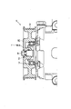
図3は動力伝達装置1の断面図である。
本実施例の動力伝達装置1は、第1実施例の外ハブ5と内ハブ6とを一体に構成したハブ10を具備し、このハブ10全体を樹脂または焼結金属で構成した一例である。
この構成では、シャフト2がロックした時に、シャフト2の外周にスプライン嵌合するハブ10のスプライン部10aに応力が集中して、そのスプライン部10aが破壊されることにより、シャフト2とハブ10との結合状態が解除されて、両者間のトルク伝達が遮断される。
【0020】
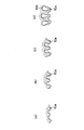
なお、ハブ10のスプライン部10aは、シャフト2がロックした時に確実に破壊される必要がある。そこで、スプライン部10aの破壊を容易にするために、図4(a)に示す通常のスプライン部10aに対し、例えば図4(b)、(c)に示すように、スプライン部10aの歯丈を長くして、歯元の応力集中を高めるように構成しても良い。
あるいは図4(d)に示すように、スプライン部10aの内側に欠肉部10bを設けることで、歯元の応力集中を高めるように構成しても良い。
【0021】
(第3実施例)
図5は動力伝達装置1の断面図である。
本実施例の動力伝達装置1は、第1実施例と同様に、外ハブ5と内ハブ6とを有する構成であるが、その外ハブ5と内ハブ6との結合状態が第1実施例とは異なる。
外ハブ5は、樹脂製であり、その外周部でゴム体4を介してプーリ3に連結されている。
内ハブ6は、金属製(例えば鉄鋼)であり、外ハブ5の内周部にインサート成形され、シャフト2の外周にスプライン嵌合して結合される。
【0022】
但し、外ハブ5の内周部と内ハブ6の外周部には、両者を結合する結合部A(図6参照)が設けられて、互いに回転規制されている。
なお、図6(a)に示す結合部Aは、外ハブ5の内周部と内ハブ6の外周部に各々設けられたスプライン部を噛み合わせて構成され、図6(b)に示す結合部Aは、波形の凹凸部を噛み合わせて構成され、図6(c)に示す結合部Aは、内ハブ6の外周面に設けた偏心溝6cに外ハブ5の樹脂が入り込んで構成されている。
本実施例の構成では、シャフト2がロックした時に、樹脂で構成された外ハブ5の結合部に応力が集中して破壊されることにより、外ハブ5と内ハブ6との結合状態が解除されて、両者間のトルク伝達が遮断される。
【0023】
(第4実施例)
図7は動力伝達装置1の断面図である。
本実施例の動力伝達装置1は、第3実施例と同様に、樹脂製の外ハブ5と金属製の内ハブ6とを有する構成であるが、その外ハブ5と内ハブ6との結合状態が第3実施例とは異なる。
外ハブ5と内ハブ6は、それぞれ別々に成形され(インサート成形ではない)、両者の結合部Aで結合されて互いに回転規制されている。なお、結合部Aは、例えば第3実施例で説明した構成(図6参照)で、且つ軸方向にテーパ形状(図7参照)を有している。
【0024】
本実施例の構成では、シャフト2がロックした時に、樹脂で構成された外ハブ5の結合部に応力が集中して破壊されることにより、外ハブ5と内ハブ6との結合状態が解除されて、両者間のトルク伝達が遮断される。
また、外ハブ5と内ハブ6との結合部Aを軸方向にテーパ形状とすることにより、外ハブ5と内ハブ6とを組み付けた際のがたつきを防止できるメリットがある。
【0025】
(第5実施例)
図8は動力伝達装置1の断面図である。
本実施例の動力伝達装置1は、第2実施例と同様に、外ハブ5と内ハブ6とを一体に構成したハブ10を有しているが、ハブ10とシャフト2との結合状態が第2実施例とは異なる。
本実施例のハブ10とシャフト2は、図8に示すように、両者のテーパ嵌合によって結合され、且つハブ10は樹脂で構成されている。
この場合、シャフト2がロックすると、シャフト2のテーパ面に対してハブ10のテーパ嵌合面が滑るため、摩擦熱が発生してハブ10のテーパ嵌合面が摩耗することにより、シャフト2とハブ10との結合状態が解除されて、両者間のトルク伝達が遮断される。
【0026】
(第6実施例)
図9〜図11はそれぞれ動力伝達装置1の断面図である。
本実施例の動力伝達装置1は、プーリ3を樹脂化することでゴム体4(図1参照)によるダンパ機能を廃止したもので、その代表的な実施例を図9〜図11に示す。
プーリ3を樹脂化すると、金属製(例えば鉄鋼)のプーリ3と比較してプーリ3の慣性モーメントが小さくなるため、ゴム体4によるダンパ機能を設けなくても、圧縮機のトルク変動を小さく抑えることが可能である。
【0027】
図9に示す構成は、例えば第2実施例に示したハブ10とプーリ3とを一体化したもので、シャフト2がロックした時は、第2実施例と同様にハブ10のスプライン部10aが破壊されることで、シャフト2とハブ10との結合状態が解除されて、両者間のトルク伝達が遮断される。
図10に示す構成は、例えば第3実施例に示した外ハブ5とプーリ3とを一体化したもので、シャフト2がロックした時は、第3実施例と同様に外ハブ5の結合部が破壊されることで、外ハブ5と内ハブ6との結合状態が解除されて、両者間のトルク伝達が遮断される(この場合、第4実施例の構成にも適用できる)。
図11に示す構成は、例えば第5実施例に示したハブ10とプーリ3とを一体化したもので、シャフト2がロックした時は、第5実施例と同様にハブ10のテーパ嵌合面が摩耗することにより、シャフト2とハブ10との結合状態が解除されて、両者間のトルク伝達が遮断される。
【図面の簡単な説明】
【図1】動力伝達装置の断面図である(第1実施例)。
【図2】内ハブと外ハブとの斜視図である(第1実施例)。
【図3】動力伝達装置の断面図である(第2実施例)。
【図4】樹脂製ハブに形成されるスプライン部の断面図である。
【図5】動力伝達装置の断面図である(第3実施例)。
【図6】内ハブと外ハブとの結合状態を示す断面図である(第3実施例)。
【図7】動力伝達装置の断面図である(第4実施例)。
【図8】動力伝達装置の断面図である(第5実施例)。
【図9】動力伝達装置の断面図である(第6実施例)。
【図10】動力伝達装置の断面図である(第6実施例)。
【図11】動力伝達装置の断面図である(第6実施例)。
【符号の説明】
1 動力伝達装置
2 シャフト(回転軸)
5 外ハブ(第2のハブ)
6 内ハブ(第1のハブ)
10 ハブ
A 内ハブと外ハブとの結合部[0001]
BACKGROUND OF THE INVENTION
The present invention relates to a power transmission device that transmits torque to a rotating shaft of a rotating device, and more particularly to a structure for interrupting transmission of overload torque.
[0002]
[Prior art]
As a conventional technique, for example, a power transmission device disclosed in JP-A-10-47244 is known. This power transmission device is provided, for example, in a compressor of a refrigeration cycle and transmits the rotational power of the engine to the shaft of the compressor. The power transmission device is fitted to a pulley to which the rotational power is transmitted from the engine and the shaft of the compressor. Since there is no clutch mechanism between the hub and the mating hub, a torque limiter capable of interrupting torque transmission when the shaft is locked is provided.
[0003]
This torque limiter has an interposed member having an elastically deforming portion made of a thermoplastic resin, and the interposed member is coupled to one of a pulley and a hub and is pressed against the other so as to be always integrally rotatable. ing. With this configuration, when the load torque on the shaft side fluctuates, the elastic deformation part elastically deforms to absorb the torque fluctuation, and when the load torque becomes excessive (when the shaft is locked, etc.) When the elastically deforming portion is melted by the frictional heat accompanying the relative sliding, the transmission of the overload torque from the shaft to the pulley is interrupted.
[0004]
[Problems to be solved by the invention]
However, in the above configuration, the number of parts increases, and a space for arranging the interposition member in front of the bearing that supports the pulley is required. Therefore, the overall size of the compressor including the power transmission device is large. It has a problem of becoming.
The present invention has been made based on the above circumstances, and an object of the present invention is to provide a power transmission device that can reduce the number of parts and can reduce the size of the rotating device.
[0005]
[Means for Solving the Problems]
(Means of Claim 1)
According to the power transmission device of the first aspect, the hub is coupled to the first hub coupled to the rotating shaft, and the torque transmitted from the external drive source is coupled to the first hub. And at least one side of the first hub and the second hub is made of resin or sintered metal. In addition, the first hub and the second hub are restricted in rotation by their joint portions engaging with each other, and the first hub is a flange portion that faces the inner peripheral side of the second hub in the axial direction. And a convex portion corresponding to the concave portion provided in the second hub is provided radially on a surface of the flange portion facing the inner peripheral side of the second hub. The hub is coupled in a substantially axial direction by fitting a concave portion and a convex portion.
As a result, when the hub on one side made of resin or sintered metal is overloaded due to an abnormality on the rotating device side, the connecting portion with the hub on the other side is destroyed, so that Torque transmission can be cut off.
[0009]
(Means of Claim 2 )
According to the power transmission device of the second aspect, the power transmission device has a hub that rotates by receiving torque transmitted from an external drive source and is coupled to the rotation shaft of the rotation device, and the torque is applied to the rotation shaft through the hub. a performs a transmission, the hub is composed of a resin or a sintered metal.
When this hub made of resin or sintered metal is overloaded due to an abnormality on the rotating device side, the torque transmission to the rotating shaft may be interrupted by breaking the joint with the rotating shaft. it can.
Further, the hub is splined by spline fitting to the outer periphery of the rotating shaft, and a lacking portion is provided inside the spline portion .
[0014]
DETAILED DESCRIPTION OF THE INVENTION
Next, embodiments of the present invention will be described with reference to the drawings.
(First embodiment)
FIG. 1 is a cross-sectional view of the
The
[0015]
The
The
[0016]
The
As shown in FIG. 1, the
In addition, the material which comprises the
[0017]
Next, the operation of this embodiment will be described.
Rotational power transmitted from the vehicle engine to the
Here, for example, when the
[0018]
(Effects of the first embodiment)
In the
[0019]
(Second embodiment)
FIG. 3 is a cross-sectional view of the
The
In this configuration, when the
[0020]
The
Or as shown in FIG.4 (d), you may comprise so that the stress concentration of a tooth root may be raised by providing the lacking
[0021]
(Third embodiment)
FIG. 5 is a cross-sectional view of the
As in the first embodiment, the
The
The
[0022]
However, the inner peripheral portion of the
The coupling portion A shown in FIG. 6 (a) is configured by meshing the inner peripheral portion of the
In the configuration of the present embodiment, when the
[0023]
(Fourth embodiment)
FIG. 7 is a cross-sectional view of the
As in the third embodiment, the
The
[0024]
In the configuration of the present embodiment, when the
Further, by forming the joint portion A between the
[0025]
(5th Example)
FIG. 8 is a cross-sectional view of the
As in the second embodiment, the
As shown in FIG. 8, the
In this case, when the
[0026]
(Sixth embodiment)
9-11 is sectional drawing of the
The
If the
[0027]
The configuration shown in FIG. 9 is an example in which the
The configuration shown in FIG. 10 is an example in which the
The configuration shown in FIG. 11 is an example in which the
[Brief description of the drawings]
FIG. 1 is a cross-sectional view of a power transmission device (first embodiment).
FIG. 2 is a perspective view of an inner hub and an outer hub (first embodiment).
FIG. 3 is a cross-sectional view of a power transmission device (second embodiment).
FIG. 4 is a cross-sectional view of a spline portion formed on a resin hub.
FIG. 5 is a sectional view of a power transmission device (third embodiment).
FIG. 6 is a cross-sectional view showing a coupling state between an inner hub and an outer hub (third embodiment).
FIG. 7 is a sectional view of a power transmission device (fourth embodiment).
FIG. 8 is a cross-sectional view of a power transmission device (fifth embodiment).
FIG. 9 is a sectional view of a power transmission device (sixth embodiment).
FIG. 10 is a sectional view of a power transmission device (sixth embodiment).
FIG. 11 is a sectional view of a power transmission device (sixth embodiment).
[Explanation of symbols]
1
5 Outer hub (second hub)
6 Inner hub (first hub)
10 Hub A Joint between the inner hub and outer hub
Claims (2)
前記ハブは、前記回転軸に結合される第1のハブと、この第1のハブに結合されて、外部の駆動源より伝達されたトルクを前記第1のハブに伝達する第2のハブとを有し、前記第1のハブと第2のハブとの少なくとも一方側が樹脂または焼結金属で構成され、その一方側のハブは、前記回転装置側の異常により過負荷となった時に、他方側のハブとの結合部が破壊されることにより、前記回転軸へのトルク伝達を遮断する動力伝達装置であって、
前記第1のハブと前記第2のハブは、両者の前記結合部が噛み合うことで互いに回転規制されており、
前記第1のハブは、前記第2のハブの内周側と軸方向に対向するフランジ部を有し、
前記フランジ部の前記第2のハブの内周側と対向する面に、前記第2のハブに設けられた凹部に対応する凸部が放射状に設けられており、
前記第1のハブと前記第2のハブとは、前記凹部と前記凸部とを嵌合させて、略軸方向に結合されていることを特徴とする動力伝達装置。It has a hub that rotates by receiving torque transmitted from an external drive source, and transmits torque to the rotating shaft of the rotating device via this hub.
The hub includes a first hub coupled to the rotating shaft, and a second hub coupled to the first hub and transmitting torque transmitted from an external driving source to the first hub. And at least one side of the first hub and the second hub is made of resin or sintered metal, and the hub on the one side is overloaded when an abnormality occurs on the rotating device side. A power transmission device that cuts off torque transmission to the rotating shaft by breaking a connecting portion with a hub on the side;
The first hub and the second hub are restricted in rotation with each other by engaging the coupling portion of both,
The first hub has a flange portion that is axially opposed to the inner peripheral side of the second hub,
Convex portions corresponding to the concave portions provided in the second hub are provided radially on the surface of the flange portion facing the inner peripheral side of the second hub,
The power transmission device, wherein the first hub and the second hub are coupled in a substantially axial direction by fitting the concave portion and the convex portion.
前記ハブは、樹脂または焼結金属で構成されており、前記回転装置側の異常により過負荷となった時に、前記回転軸との結合部が破壊されることにより、前記回転軸へのトルク伝達を遮断する動力伝達装置であって、
前記ハブは、前記回転軸の外周にスプライン嵌合して回転規制されており、
スプライン部の内側に欠肉部が設けられていることを特徴とする動力伝達装置。 It has a hub that rotates in response to torque transmitted from an external drive source and is coupled to the rotating shaft of the rotating device, and transmits torque to the rotating shaft through this hub,
The hub is made of resin or sintered metal, and when an overload occurs due to an abnormality on the rotating device side, a torque transmission to the rotating shaft is caused by breaking a coupling portion with the rotating shaft. A power transmission device that shuts off
The hub is restricted in rotation by spline fitting to the outer periphery of the rotating shaft,
A power transmission device, wherein a thinned portion is provided inside a spline portion .
Priority Applications (5)
| Application Number | Priority Date | Filing Date | Title |
|---|---|---|---|
| JP21340799A JP4078761B2 (en) | 1999-07-28 | 1999-07-28 | Power transmission device |
| DE20023516U DE20023516U1 (en) | 1999-06-21 | 2000-06-19 | Rotation transmission device for vehicle air-conditioning unit compressor; has torque-limiting unit to interrupt rotation transmission from pulley to output disc if torque difference exceeds threshold |
| US09/597,831 US6332842B1 (en) | 1999-06-21 | 2000-06-19 | Rotation transmitter having torque limiting mechanism |
| DE10066236.6A DE10066236B4 (en) | 1999-06-21 | 2000-06-19 | Circulation transmission device with torque limiting device |
| DE10030068.5A DE10030068B4 (en) | 1999-06-21 | 2000-06-19 | Circulation transmission device with torque limiting device |
Applications Claiming Priority (1)
| Application Number | Priority Date | Filing Date | Title |
|---|---|---|---|
| JP21340799A JP4078761B2 (en) | 1999-07-28 | 1999-07-28 | Power transmission device |
Publications (2)
| Publication Number | Publication Date |
|---|---|
| JP2001041308A JP2001041308A (en) | 2001-02-13 |
| JP4078761B2 true JP4078761B2 (en) | 2008-04-23 |
Family
ID=16638726
Family Applications (1)
| Application Number | Title | Priority Date | Filing Date |
|---|---|---|---|
| JP21340799A Expired - Fee Related JP4078761B2 (en) | 1999-06-21 | 1999-07-28 | Power transmission device |
Country Status (1)
| Country | Link |
|---|---|
| JP (1) | JP4078761B2 (en) |
Families Citing this family (11)
| Publication number | Priority date | Publication date | Assignee | Title |
|---|---|---|---|---|
| JP4613432B2 (en) * | 2001-03-15 | 2011-01-19 | 株式会社デンソー | Power transmission device |
| JP2003106253A (en) * | 2001-09-27 | 2003-04-09 | Toyota Industries Corp | Compressor |
| JP3915486B2 (en) * | 2001-11-26 | 2007-05-16 | 株式会社デンソー | Torque transmission device |
| JP3956704B2 (en) * | 2002-01-10 | 2007-08-08 | 株式会社豊田自動織機 | Torque limiter |
| KR100799552B1 (en) * | 2002-02-21 | 2008-01-31 | 한라공조주식회사 | Pulley assembly for clutchless compressor |
| KR100885619B1 (en) * | 2002-11-14 | 2009-02-24 | 한라공조주식회사 | Clutchless Compressor with Parting Part |
| DE102004002668A1 (en) * | 2004-01-18 | 2005-09-22 | Bakelite Ag | Mechanism for transmitting a torque from a motor to a compressor comprises an overload protection device consisting of a metal limiter ring with internal radial protrusions, and a plastic driver |
| JP2005226451A (en) * | 2004-02-10 | 2005-08-25 | Zexel Valeo Climate Control Corp | Torque transmission device of compressor |
| JP4561411B2 (en) * | 2004-10-26 | 2010-10-13 | 株式会社デンソー | Power transmission device |
| FR2914720B1 (en) * | 2007-04-04 | 2010-02-12 | Skf Ab | ROLLER OR ROLLER DEVICE |
| JP6248773B2 (en) | 2014-04-17 | 2017-12-20 | 株式会社デンソー | Power transmission device |
-
1999
- 1999-07-28 JP JP21340799A patent/JP4078761B2/en not_active Expired - Fee Related
Also Published As
| Publication number | Publication date |
|---|---|
| JP2001041308A (en) | 2001-02-13 |
Similar Documents
| Publication | Publication Date | Title |
|---|---|---|
| EP3453906B1 (en) | Joint for torque transmission and electric power steering device | |
| JP6652194B2 (en) | Joint for torque transmission and electric power steering device | |
| JP4081473B2 (en) | Device for transmitting engine torque to the compressor | |
| JP4078761B2 (en) | Power transmission device | |
| US4838395A (en) | Torsion damping device | |
| JP4297194B2 (en) | Power transmission mechanism | |
| US20070179000A1 (en) | Device for transmitting torque | |
| US6893368B2 (en) | Driving force transmission apparatus | |
| JPWO2017154870A1 (en) | Torque transmission joint and electric power steering device | |
| JP4273595B2 (en) | Power transmission device | |
| US7270606B2 (en) | Power transmission device | |
| US7726449B2 (en) | Damper assembly with torque limiter | |
| WO2016047188A1 (en) | Torque transmitting joint and electric power steering device | |
| JP2001173759A (en) | Power transmission device | |
| JPWO2019022015A1 (en) | Joint for torque transmission and electric power steering device | |
| KR100653695B1 (en) | Clutchless Compressor with Connecting Part Shaped with Parting Part | |
| JP2000179568A (en) | Power transmission | |
| JP4240147B2 (en) | Power transmission mechanism | |
| JP4613432B2 (en) | Power transmission device | |
| JP4353102B2 (en) | Power transmission device | |
| JP6801777B2 (en) | Torque transmission fittings and electric power steering device | |
| JP3928444B2 (en) | Power transmission device having torque limiter | |
| KR100694629B1 (en) | Plate of wide angle universal joint | |
| JP2002089626A (en) | Damper assembly | |
| JP2005016615A (en) | Friction disc assembly |
Legal Events
| Date | Code | Title | Description |
|---|---|---|---|
| A621 | Written request for application examination |
Free format text: JAPANESE INTERMEDIATE CODE: A621 Effective date: 20050818 |
|
| A977 | Report on retrieval |
Free format text: JAPANESE INTERMEDIATE CODE: A971007 Effective date: 20070518 |
|
| A131 | Notification of reasons for refusal |
Free format text: JAPANESE INTERMEDIATE CODE: A131 Effective date: 20070619 |
|
| A521 | Written amendment |
Free format text: JAPANESE INTERMEDIATE CODE: A523 Effective date: 20070810 |
|
| A131 | Notification of reasons for refusal |
Free format text: JAPANESE INTERMEDIATE CODE: A131 Effective date: 20071012 |
|
| A521 | Written amendment |
Free format text: JAPANESE INTERMEDIATE CODE: A523 Effective date: 20071207 |
|
| TRDD | Decision of grant or rejection written | ||
| A01 | Written decision to grant a patent or to grant a registration (utility model) |
Free format text: JAPANESE INTERMEDIATE CODE: A01 Effective date: 20080115 |
|
| A61 | First payment of annual fees (during grant procedure) |
Free format text: JAPANESE INTERMEDIATE CODE: A61 Effective date: 20080128 |
|
| FPAY | Renewal fee payment (event date is renewal date of database) |
Free format text: PAYMENT UNTIL: 20110215 Year of fee payment: 3 |
|
| R150 | Certificate of patent or registration of utility model |
Ref document number: 4078761 Country of ref document: JP Free format text: JAPANESE INTERMEDIATE CODE: R150 Free format text: JAPANESE INTERMEDIATE CODE: R150 |
|
| FPAY | Renewal fee payment (event date is renewal date of database) |
Free format text: PAYMENT UNTIL: 20120215 Year of fee payment: 4 |
|
| FPAY | Renewal fee payment (event date is renewal date of database) |
Free format text: PAYMENT UNTIL: 20130215 Year of fee payment: 5 |
|
| FPAY | Renewal fee payment (event date is renewal date of database) |
Free format text: PAYMENT UNTIL: 20140215 Year of fee payment: 6 |
|
| R250 | Receipt of annual fees |
Free format text: JAPANESE INTERMEDIATE CODE: R250 |
|
| R250 | Receipt of annual fees |
Free format text: JAPANESE INTERMEDIATE CODE: R250 |
|
| R250 | Receipt of annual fees |
Free format text: JAPANESE INTERMEDIATE CODE: R250 |
|
| R250 | Receipt of annual fees |
Free format text: JAPANESE INTERMEDIATE CODE: R250 |
|
| R250 | Receipt of annual fees |
Free format text: JAPANESE INTERMEDIATE CODE: R250 |
|
| LAPS | Cancellation because of no payment of annual fees |