JP4076552B2 - Panel fence - Google Patents
Panel fence Download PDFInfo
- Publication number
- JP4076552B2 JP4076552B2 JP2005290855A JP2005290855A JP4076552B2 JP 4076552 B2 JP4076552 B2 JP 4076552B2 JP 2005290855 A JP2005290855 A JP 2005290855A JP 2005290855 A JP2005290855 A JP 2005290855A JP 4076552 B2 JP4076552 B2 JP 4076552B2
- Authority
- JP
- Japan
- Prior art keywords
- panel
- fence
- plate
- panel fence
- frame
- Prior art date
- Legal status (The legal status is an assumption and is not a legal conclusion. Google has not performed a legal analysis and makes no representation as to the accuracy of the status listed.)
- Expired - Fee Related
Links
- 229910000831 Steel Inorganic materials 0.000 description 5
- 238000010276 construction Methods 0.000 description 5
- 239000010959 steel Substances 0.000 description 5
- 230000003014 reinforcing effect Effects 0.000 description 3
- 238000003466 welding Methods 0.000 description 2
- 230000004888 barrier function Effects 0.000 description 1
- 239000000463 material Substances 0.000 description 1
- 239000002184 metal Substances 0.000 description 1
- 229920003002 synthetic resin Polymers 0.000 description 1
- 239000000057 synthetic resin Substances 0.000 description 1
Images


Landscapes
- Refuge Islands, Traffic Blockers, Or Guard Fence (AREA)
- Fencing (AREA)
Description
本発明は、道路の路端や、建設現場、建物周辺等に設置する、パネルフェンスに関する。 The present invention relates to a panel fence installed on a road edge, a construction site, around a building, and the like.
パネルフェンスは支柱とパネルが通常、上部、中間部及び下部の三箇所において連結用の金具やボルト、ナットにより連結されており多種の金具等を必要とするためコストが嵩むと共に連結作業に多大な時間を要した。 The panel fence is usually connected to the upper part, the middle part, and the lower part of the panel fence by connecting brackets, bolts and nuts, and requires a variety of brackets. It took time.
そこで支柱にパネルをセットしてキャップを取り付けて組立て、多種、多数の金具を不要とし、連結作業時間の短縮を図ったパネルフェンスがある。
パネルフェンスは工事現場等を道路や生活空間から遮蔽し、第三者の災害防止、防塵、防音等を目的として立設されるため、外観は軽視され、デザイン性の高いパネルフェンスはなかった。 Since the panel fence shields the construction site from roads and living spaces and is erected for the purpose of preventing third-party disasters, dustproofing, soundproofing, etc., the appearance was neglected and there was no panel fence with high design.
又、従来のパネルフェンスは縦約800mm、横幅1800mmのパネルを二枚、縦方向から枠へと立て込んでいたため一枚のパネルの嵩が大きく重いので運搬や取扱が不便であった。又、下のパネルを取り替えるときは上のパネルも取り外さねばならず使い勝手が悪かった。 In addition, the conventional panel fence has two panels having a length of about 800 mm and a width of 1800 mm, which are set up in the frame from the vertical direction, so that the bulk of one panel is large and heavy, and transportation and handling are inconvenient. Also, when replacing the lower panel, the upper panel had to be removed, which was unusable.
図8が従来のパネルフェンスの使用状態を示す説明図である。 FIG. 8 is an explanatory view showing a use state of a conventional panel fence.
スチ−ルをネット状に張設したネットパネル46を上段に、パネル48の中央に鉄筋49を溶接して補強した板状パネル47を下段に取り付けた状態を示している。横幅1800mmの板状パネル47は、風であおられやすく、ぱたぱたと大きな音を立てるため鉄筋による補強が施されている。ネットパネル46の両側には支柱50、51に係架するためのフック52から55を形成し、板状パネル47の両側にも支柱への取り付け用フック56から59を形成する。支柱50、51に取り付けたパネル係着手段62、63、66、67にまず、下段パネルとなる板状パネル47を係架し、次に支柱50、51のパネル係着手段60、61、64、65に上段のネットパネルのフック52から55を係架してパネルを設置するのである。
A state in which a
パネルの側縁に形成したフックを支柱に係架させて設置するためパネルフェンス間に隙間が生じるだけでなく、支柱も露出した状態となり、見栄えが悪かった。又、パネルと同数の支柱が必要となり、コスト高となるうえ、施行に手間や時間がかかった。 Since the hooks formed on the side edges of the panel were suspended from the support column, not only was there a gap between the panel fences, but the support column was also exposed, and the appearance was poor. In addition, the same number of columns as the panel is required, which increases the cost and takes time and effort to implement.
そこで、本発明では、運搬、施行が容易で、パネル間の隙間を無くして支軸を望見できないようにし、また、パネル枠を三面としてデザイン性の高い良好な外観を有するパネルフェンスを提供することを目的とする。 Accordingly, the present invention provides a panel fence that is easy to transport and enforce, eliminates the gap between the panels so that the support shaft cannot be seen, and has a good appearance with high design with three panel frames. For the purpose.
断面がコ字形状を呈する側板の開口面を下方に向けて天板を形成し、二本の側板の開口面を上下に向けて桟を形成し、側板の開口面を上方に向けて底板を形成し、水平方向にパ
ネルをスライドさせる溝を複数形成する。次に、側板の両端部の外側に一対の支柱パイプを取り付けると共に長手方向の一辺にパネルのストッパ片を複数取り付け、枠本体の裏面に支軸連結フックを設けるのである。このように形成した枠本体のスライド溝にパネルを出し入れ自在に装着するのである。
The top plate is formed with the opening surface of the side plate having a U-shaped cross-section facing downward, the opening surfaces of the two side plates are directed up and down, and the crosspiece is formed with the opening surface of the side plate facing upward. A plurality of grooves are formed to slide the panel in the horizontal direction. Next, a pair of support pipes are attached to the outside of both end portions of the side plate, a plurality of panel stopper pieces are attached to one side in the longitudinal direction, and a spindle connecting hook is provided on the back surface of the frame body. The panel can be inserted into and removed from the slide groove of the frame body formed in this manner.
1、三面からなる一体型枠を予め成形し、各面にデザインパネルを横方向からスライドさせて挿入するため、一枚のパネルが約600mmx1000mmとなり、軽量且つ嵩が低く、運搬、施工が容易である。従来のパネルは横幅が1800mmあり、横風にあおられやすく、そのため中央に補強用の鉄筋を備える必要があったが本願発明のパネルは横幅が短い上、桟に嵌め込むため補強がなくてもがたつかない。 1. Forming an integrated mold consisting of three surfaces in advance, and sliding the design panel from each side into the surface. The single panel is approximately 600mm x 1000mm, lightweight and low in volume, and easy to transport and install. is there. The conventional panel has a width of 1800 mm and is easily swept by the crosswind, so it was necessary to provide a reinforcing bar in the center. It wo n’t work.
また、三面のパネルを組み合わせることで、市松模様や安全十字のマ−ク等デザインのバリエ−ションが広がり、単なる遮断壁としてでなく広告宣伝効果が拡大する。 In addition, combining three panels expands design variations, such as checkered patterns and safety cross marks, and increases the advertising effectiveness, not just a barrier.
三枚のパネルにそれぞれの出入口があるため、どのパネルの入れ替えも他のパネルを取り外すことなく簡単に行える。
2、支軸連結フックがパネル枠の裏面にあるため、パネル枠間の隙間が全く生じず、又、支軸がパネル本体の裏面に隠れて正面からは全く望見しない。また、パネルと同数必要であった支軸の数を半分程度まで減らすことができコストダウンを図ると共に施工が楽である。
3、天板、桟及び底板に同一の側板を使用するため部材の種類が少なく、コストダウンを図ることができる。
Since each of the three panels has a doorway, any panel can be easily replaced without removing the other panels.
2. Since the support shaft connecting hook is on the back surface of the panel frame, there is no gap between the panel frames, and the support shaft is hidden behind the back surface of the panel body and is not expected from the front. In addition, the number of supporting shafts, which is the same as the number of panels, can be reduced to about half, so that the cost can be reduced and the construction is easy.
3. Since the same side plate is used for the top plate, the crosspiece, and the bottom plate, the number of types of members is small, and the cost can be reduced.
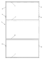
次に、本発明の最良の実施形態について図面を参照しながら詳細に説明する。 図1がパネルフェンス1の正面図、図2が同、左側面図、3が同、右側面図である。 Next, the best embodiment of the present invention will be described in detail with reference to the drawings. 1 is a front view of the panel fence 1, FIG. 2 is a left side view thereof, and FIG. 3 is a right side view thereof.
パネルフェンス1は上下方向に長いスチ−ル製の枠体であって、左右二本ずつの角パイプからなる左右の支柱2−2、3−3と支柱2−3間に架橋する天板4、上下の桟5、6及び底板7と支柱3−3側の外側に複数個取り付けたストッパ片8と支柱2、3の上下に取り付けたフック9、10から構成される。
The panel fence 1 is a frame made of steel that is long in the vertical direction, and is a top plate 4 that bridges between the left and right columns 2-2, 3-3 and the column 2-3, each composed of two right and left square pipes. The upper and
支柱2、3に使用されるのは10mmx22mm、長さ1740mmのスチ−ル製の角パイプである。
A steel square pipe having a size of 10 mm × 22 mm and a length of 1740 mm is used for the
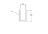
また、天板、底板及び桟に使用するのは図4に示す、断面コ字状の側板11である。側板11は溝幅10mm、高さ18mm、厚さ3mm、長さ1055mmのスチ−ル製である。
Further, a
また、ストッパ片には30mmx40mmのプラスチックあるいはスチ−ル製の板片を使用する。 The stopper piece is a 30 mm x 40 mm plastic or steel plate.
まず、二本の側板11を開口面を上下に向けて三点で点溶接し、上桟5、下桟6を形成する。天板4は側板11の開口面を下に向け、底板7は開口面を上に向けて配置する。天板4、上桟5、下桟6及び底板7を所要間隔を隔てて配置した後、それぞれの側板11の両端部の外側に左右の支柱2−2、3−3をそれぞれ溶接により固着し、枠本体を形成する。
First, the two
枠本体1の右側面にはストッパ片8を所要間隔を隔てて6箇所取り付ける。
パネルフェンスは隙間なく連結するためストッパ片8は右側面だけで足り、パネルがパネルフェンスから抜け出ることはない。
Six
Since the panel fence is connected without a gap, the
また、フック9、10は予めパネルフェンス背面側の支柱2−3の上下に取り付けておく。パネルフェンス設置時に、パネルフェンスの背面に立設したパネルフェンス支持支柱とフック9、10をクランプで連結するのである。
The
このように形成したパネルフェンス1を立設し、天板4、上桟5、下桟6及び底板7によって形成されたスライド溝にパネル(図示せず)を左方向からスライド挿入するのである。
The panel fence 1 formed in this way is erected, and a panel (not shown) is slid and inserted into the slide groove formed by the top plate 4, the
パネルは合成樹脂材製または厚紙製であって、軽量、且つ、着色やデザインが自在である。 The panel is made of a synthetic resin material or cardboard, is lightweight, and can be freely colored and designed.
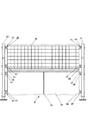
図6は実際にパネルフェンスを立設した状態を正面から見た説明図である。 FIG. 6 is an explanatory view of the state in which the panel fence is actually erected as viewed from the front.
前述の様に形成した枠本体12、13及び14にパネル15から20をそれぞれスライド挿入する。このようにして形成したパネルフェンスを、枠本体の裏面に取り付けたフックにクランプを係止して、パネルフェンスの背後に予め組立てておいた縦支柱21、22に架橋した横支柱23にクランプ24、25で固定して立設するのである。枠本体12、13、14は格子状のパネル26、27が挿入されているタイプである。
The panels 15 to 20 are slid into the
このように三面のパネルから構成される一体型パネルフェンスの一部にパネルの変わりに格子状のパネルを挿入して圧迫感を与えないパネルフェンスを形成することができ、又、全体として市松模様や安全十字のマ−クを呈するフェンスを形成することも可能となり、デザインのバリエ−ションが豊富である。 In this way, it is possible to form a panel fence that does not give a feeling of pressure by inserting a grid-like panel instead of a panel into a part of an integrated panel fence composed of three panels, and as a whole checkered pattern It is also possible to form a fence that exhibits a safety cross mark, and there are many design variations.
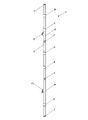
図7は他のパネルフェンスの立設状態を背面側から見た説明図である。 FIG. 7 is an explanatory view of another panel fence standing from the back side.
従来は、パネル枠を一枚ずつ支持支柱に係止し、パネル枠の側面に設けたフックと縦支軸をクランプで連結して次のパネル枠と連結して施工していた。そのため、支持支柱の立設とパネル枠の係架を同時に行わなければならず、施工に手間取っていた。しかし、本願においては、まず、パネル枠の背面側に支持支柱だけを予め立設することが可能である。斜め軸35、36及び37で支えた縦支軸30、31及び32に横方向の支柱33、34をそれぞれクランプ38から43で連結して支持支柱を先に組立てるのである。
Conventionally, the panel frame is locked to the support column one by one, and the hook and the longitudinal support shaft provided on the side surface of the panel frame are connected by a clamp and connected to the next panel frame. For this reason, it was necessary to carry out the support column and the panel frame at the same time, which took time. However, in the present application, first, it is possible to stand in advance only the support column on the back side of the panel frame. The support columns are assembled first by connecting the
次に、前述のように形成した枠本体にパネルをそれぞれ挿入したパネルフェンス28、29を所望枚数横方向に連続させて、パネルフェンスの縦枠の背面に設けたフックにクランプ44、45を係止して横方向の支柱33、34に連結するのである。予め支持支柱を立設し、それにパネルフェンスを係架していくだけでパネルフェンスの立設が完了するため施工時間が大幅に短縮し、さらに、従来、パネルフェンス同士を連結していた縦支軸がパネルフェンスの裏面に完全に隠れるため、正面からは全く望見せず、また縦支軸の数も従来の半分程度まで減らすことができるのである。
Next, a desired number of
本発明は、道路の路端、建設現場、建物周辺等に設置するパネルフェンスに利用することができ、一体型枠の三面それぞれにパネルをスライド挿入することができるため、単に、防音、防塵等の役目だけでなく、広告塔として利用することもできる。 The present invention can be used for panel fences installed on roadsides, construction sites, buildings, and the like, and since panels can be slid into each of the three surfaces of the integrated frame, simply soundproofing, dustproofing, etc. It can also be used as an advertising tower.
1、パネルフェンス 2、左支柱 3、右支柱 4、天板 5、上桟 6、下桟 7、底板 8、ストッパ 9、10、フック 11、側板15、16、17、18、19、20、パネル
1,
Claims (1)
スライド溝にパネルを出し入れ自在に装着したパネルフェンス。 A horizontally-sliding groove with the U-shaped side plate opening face facing downwards as a top plate, the opening surfaces of the two side plates facing upwards and downwards, and the side plate opening surface facing upwards as a bottom plate Attaching a pair of struts to the outside of both ends of the side plate, attaching a plurality of stopper pieces to one end of the groove, and attaching a spindle connecting hook to the pillar on the back side of the panel,
Panel fence with a panel that can be inserted and removed freely in the slide groove.
Priority Applications (1)
| Application Number | Priority Date | Filing Date | Title |
|---|---|---|---|
| JP2005290855A JP4076552B2 (en) | 2005-10-04 | 2005-10-04 | Panel fence |
Applications Claiming Priority (1)
| Application Number | Priority Date | Filing Date | Title |
|---|---|---|---|
| JP2005290855A JP4076552B2 (en) | 2005-10-04 | 2005-10-04 | Panel fence |
Publications (2)
| Publication Number | Publication Date |
|---|---|
| JP2007100367A JP2007100367A (en) | 2007-04-19 |
| JP4076552B2 true JP4076552B2 (en) | 2008-04-16 |
Family
ID=38027573
Family Applications (1)
| Application Number | Title | Priority Date | Filing Date |
|---|---|---|---|
| JP2005290855A Expired - Fee Related JP4076552B2 (en) | 2005-10-04 | 2005-10-04 | Panel fence |
Country Status (1)
| Country | Link |
|---|---|
| JP (1) | JP4076552B2 (en) |
Cited By (2)
| Publication number | Priority date | Publication date | Assignee | Title |
|---|---|---|---|---|
| CN103306227A (en) * | 2013-07-08 | 2013-09-18 | 中铁第四勘察设计院集团有限公司 | Light reflecting fence capable of being folded movably |
| CN112012572A (en) * | 2020-07-28 | 2020-12-01 | 浙江广盛环境建设集团有限公司 | Dust-proof and sound-proof equipment suitable for various decoration environments |
Families Citing this family (3)
| Publication number | Priority date | Publication date | Assignee | Title |
|---|---|---|---|---|
| AU2011101446B4 (en) * | 2011-11-10 | 2012-06-14 | Parratech | Soundtemp |
| CN109235327A (en) * | 2018-11-07 | 2019-01-18 | 四川省家伦再生资源科技有限公司 | A kind of isolation strip |
| CN113833354A (en) * | 2021-10-28 | 2021-12-24 | 徐州大成环境科技有限公司 | Make things convenient for dustproof isolating device for construction of dismouting |
-
2005
- 2005-10-04 JP JP2005290855A patent/JP4076552B2/en not_active Expired - Fee Related
Cited By (3)
| Publication number | Priority date | Publication date | Assignee | Title |
|---|---|---|---|---|
| CN103306227A (en) * | 2013-07-08 | 2013-09-18 | 中铁第四勘察设计院集团有限公司 | Light reflecting fence capable of being folded movably |
| CN103306227B (en) * | 2013-07-08 | 2015-08-05 | 中铁第四勘察设计院集团有限公司 | Movable folding reflective enclosing |
| CN112012572A (en) * | 2020-07-28 | 2020-12-01 | 浙江广盛环境建设集团有限公司 | Dust-proof and sound-proof equipment suitable for various decoration environments |
Also Published As
| Publication number | Publication date |
|---|---|
| JP2007100367A (en) | 2007-04-19 |
Similar Documents
| Publication | Publication Date | Title |
|---|---|---|
| CN1151780A (en) | connecting hook | |
| JP6021604B2 (en) | Temporary scaffolding and its assembly method | |
| US20130320281A1 (en) | Fence system | |
| JP4076552B2 (en) | Panel fence | |
| JP3010554B2 (en) | Partition elements for display partitions | |
| CN210622476U (en) | an assembled enclosure | |
| JP2004346681A (en) | Method of remodeling existing fence to translucent soundproof wall | |
| JP6905768B1 (en) | Road protection gantry | |
| JP2016116264A (en) | Photovoltaic power generation panel pedestal | |
| JP4675090B2 (en) | Trunk edge integrated fence panel and trunk edge integrated fence | |
| CN210460182U (en) | Assembled wind-resistant enclosure | |
| JP3989274B2 (en) | Underground structure for buildings | |
| GB2315081A (en) | Hoardings | |
| JP6401751B2 (en) | Temporary wall | |
| JP5110616B2 (en) | fence | |
| CN223398684U (en) | A decoration system for shield tunnel | |
| KR200162505Y1 (en) | Safety net for protecting falling | |
| KR101654930B1 (en) | Connection apparatus of column for concrete construction | |
| JP2000297528A (en) | Method of executing work for hanging shelf scuffold and protective sidewall and members therefor | |
| JP5163861B2 (en) | Support structure for temporary gate and its structure | |
| US20070245972A1 (en) | Barriers or partitions | |
| JP2004143881A (en) | Residual porous frame for form, concrete building frame, and construction method of concrete building frame | |
| JP2023096500A (en) | safety passage | |
| KR200428187Y1 (en) | Building Access Shelves | |
| CA2798353C (en) | Fence system |
Legal Events
| Date | Code | Title | Description |
|---|---|---|---|
| A977 | Report on retrieval |
Free format text: JAPANESE INTERMEDIATE CODE: A971007 Effective date: 20071227 |
|
| TRDD | Decision of grant or rejection written | ||
| A01 | Written decision to grant a patent or to grant a registration (utility model) |
Free format text: JAPANESE INTERMEDIATE CODE: A01 Effective date: 20080108 |
|
| A61 | First payment of annual fees (during grant procedure) |
Free format text: JAPANESE INTERMEDIATE CODE: A61 Effective date: 20080129 |
|
| R150 | Certificate of patent or registration of utility model |
Free format text: JAPANESE INTERMEDIATE CODE: R150 |
|
| FPAY | Renewal fee payment (event date is renewal date of database) |
Free format text: PAYMENT UNTIL: 20110208 Year of fee payment: 3 |
|
| FPAY | Renewal fee payment (event date is renewal date of database) |
Free format text: PAYMENT UNTIL: 20110208 Year of fee payment: 3 |
|
| FPAY | Renewal fee payment (event date is renewal date of database) |
Free format text: PAYMENT UNTIL: 20130208 Year of fee payment: 5 |
|
| LAPS | Cancellation because of no payment of annual fees |