JP4075868B2 - Purification device - Google Patents
Purification device Download PDFInfo
- Publication number
- JP4075868B2 JP4075868B2 JP2004204384A JP2004204384A JP4075868B2 JP 4075868 B2 JP4075868 B2 JP 4075868B2 JP 2004204384 A JP2004204384 A JP 2004204384A JP 2004204384 A JP2004204384 A JP 2004204384A JP 4075868 B2 JP4075868 B2 JP 4075868B2
- Authority
- JP
- Japan
- Prior art keywords
- discharge
- electrode
- water
- high voltage
- discharge electrode
- Prior art date
- Legal status (The legal status is an assumption and is not a legal conclusion. Google has not performed a legal analysis and makes no representation as to the accuracy of the status listed.)
- Expired - Lifetime
Links
Images
Landscapes
- Apparatus For Disinfection Or Sterilisation (AREA)
- Disinfection, Sterilisation Or Deodorisation Of Air (AREA)
- Electrostatic Spraying Apparatus (AREA)
- Physical Or Chemical Processes And Apparatus (AREA)
Description
本発明は、気体、液体、固体などの浄化装置に関するものである。 The present invention relates to a purification device for gas, liquid, solid and the like.
従来、イオンやオゾン等の活性粒子を利用して、食品・調理用品などの食に関連する物体や公衆衛生上で微生物が問題となる物体の表面、これらの物体を収納する空間に存在する微生物の繁殖を防止する方法が知られている。 Conventionally, using active particles such as ions and ozone, food-related items such as food and cooking utensils, the surface of objects where microorganisms are a problem in public health, and the microorganisms that exist in the space where these objects are stored There are known methods for preventing the propagation of potatoes.
例えば、空気などの気体を電離室に導いてイオン化およびオゾン化させる際の放電電流を制御することにより、所定の低濃度のオゾンと高濃度のイオンを含む気体を発生させ、前記電離室あるいはそれに連通する空間内で、あるいは電離室で発生した気体を物体に吹き付けることによって、オゾンとイオンとの相乗効果で微生物の繁殖を防止するようにした微生物繁殖防止方法および装置がある(たとえば特許文献1参照)。また、水タンクに水道水を供給させ、供給された水に吸水性の電極を浸すことにより、この水と電極と対向電極間の放電とを利用し、放電領域でより長寿命な酸化力の高いラジカルやイオン等、およびそれらを含んだ微細な水粒子を生成し、放電領域下流に放出させ、放出された領域を殺菌、脱臭、有害物質除去する放電霧化技術応用浄化装置がある。
しかしながら、上記した従来の微生物繁殖防止方法および装置は、物体の表面や収納空間に存在する微生物を処理対象とするものであるが、生成されたイオン等は非常に不安定なため、イオンとしての寿命が非常に短く、物体に吹き付けるまえに安定な物質に変化してしまい、十分に微生物の繁殖を防止することができない、という問題があった。 However, although the above-described conventional method and apparatus for preventing microbial growth are intended to treat microorganisms present on the surface of the object or the storage space, the generated ions are very unstable, There is a problem that the lifetime is very short and the substance changes to a stable substance before spraying on an object, and the propagation of microorganisms cannot be sufficiently prevented.
また、上記した従来の放電霧化技術応用浄化装置は、水を供給させなくてはならず、水がなくなれば供給、給水しなくてはならないとういう、使用者の手をわずらわす必要があった。 In addition, the above-described conventional discharge atomization technology applied purification device must supply water, and it is necessary to bother the user to supply and supply water when there is no water. there were.
本発明は上記問題を解決するもので、使用者の手をわずらわす必要なく室内の壁面やカーテン等の付着した臭気、ウイルス、かびなどの、脱臭や除菌を行う浄化装置を提供することを目的とするものである。 The present invention solves the above problems, and provides a purification device that deodorizes and disinfects odors, viruses, fungi, and the like attached to indoor wall surfaces and curtains without the need for bothering the user. It is intended.
上記課題を解決するために、本発明の浄化装置は、放電電極と、前記放電電極の対向に配置された対向電極と、前記電極間に高電圧を印加する高電圧印加手段と、放熱面と冷却面とを有するペルチェ素子とを備え、前記冷却面を前記放電電極に密着して設け、前記ペルチェ素子により前記放電電極を露点以下の温度にして前記放電電極の表面に結露水を発生させるとともに、前記高電圧印加手段によって前記放電電極と前記対向電極との間に高電圧を印加するように構成したもので、使用者の手をわずらわすことなく、無給水で、電極間に発生させた水と放電を利用し、放電領域でラジカルやイオン等、およびそれらを含んだ微細な水粒子を生成し、前記放電領域下流に放出させることができる。 In order to solve the above problems, a purification device of the present invention comprises a discharge electrode, a counter electrode disposed opposite to the discharge electrode, a high voltage applying means for applying a high voltage between the electrodes, a heat radiating surface, A Peltier element having a cooling surface, the cooling surface is provided in close contact with the discharge electrode, and the discharge electrode is caused to generate a condensed water on the surface of the discharge electrode by setting the discharge electrode to a temperature below a dew point by the Peltier element. The high voltage applying means is configured to apply a high voltage between the discharge electrode and the counter electrode, and is generated between the electrodes without supplying water without troublesome user's hand. using and discharging water is, radicals and ions in the discharge region, and generates a fine water particles containing them, it can be released to the discharge area downstream.
また、水発生手段で効率よく露点以下の温度にすることにより、無給水で水を発生させ、電極間に発生させた水と放電を利用し、放電領域でより長寿命な酸化力の高いラジカルやイオン等、およびそれらを含んだ微細な水粒子を生成し、放電領域下流に放出させ、放出された領域を殺菌、脱臭、有害物質除去する浄化装置を提供できる。 In addition, the water generation means efficiently generates a temperature below the dew point, thereby generating water with no water supply and using the water and discharge generated between the electrodes to provide a radical having a long lifetime and high oxidizing power in the discharge region. It is possible to provide a purification device that generates fine water particles containing them, ions, etc., and discharges them downstream of the discharge region, and sterilizes, deodorizes, and removes harmful substances in the discharged region.
以上のように本発明によれば、使用者の手をわずらわす必要なく室内の壁面やカーテン等の付着した臭気、ウイルス、かびなどの、脱臭や除菌を行う浄化装置を提供できる。 As described above, according to the present invention, it is possible to provide a purification device that deodorizes and disinfects odors, viruses, fungi, and the like attached to indoor wall surfaces and curtains without the need for bothering the user.
第1の発明は、放電電極と、前記放電電極の対向に配置された対向電極と、前記電極間に高電圧を印加する高電圧印加手段と、放熱面と冷却面とを有するペルチェ素子とを備え、前記冷却面を前記放電電極に密着して設け、前記ペルチェ素子により前記放電電極を露点以下の温度にして前記放電電極の表面に結露水を発生させるとともに、前記高電圧印加手段によって前記放電電極と前記対向電極との間に高電圧を印加するように構成したもので、使用者の手をわずらわすことなく、無給水で、電極間に発生させた水と放電を利用し、放電領域でラジカルやイオン等、およびそれらを含んだ微細な水粒子を生成し、前記放電領域下流に放出させることができる。 According to a first aspect of the present invention, there is provided a discharge electrode, a counter electrode disposed opposite to the discharge electrode, high voltage applying means for applying a high voltage between the electrodes , and a Peltier element having a heat dissipation surface and a cooling surface. The cooling surface is provided in close contact with the discharge electrode, the Peltier element causes the discharge electrode to have a temperature below the dew point, and generates condensed water on the surface of the discharge electrode. It is configured to apply a high voltage between the electrode and the counter electrode , without disturbing the user's hand, without water supply, using water and discharge generated between the electrodes, radicals and ions in the discharge region, and generates a fine water particles containing them, can be released to the discharge area downstream.
また、水発生手段で効率よく露点以下の温度にすることにより、無給水で水を発生させ、電極間に発生させた水と放電を利用し、放電領域でより長寿命な酸化力の高いラジカルやイオン等、およびそれらを含んだ微細な水粒子を生成し、放電領域下流に放出させ、放出された領域を殺菌、脱臭、有害物質除去する浄化装置を提供できる。 In addition, the water generation means efficiently generates a temperature below the dew point, thereby generating water with no water supply and using the water and discharge generated between the electrodes to provide a radical having a long lifetime and high oxidizing power in the discharge region. It is possible to provide a purification device that generates fine water particles containing them, ions, etc., and discharges them downstream of the discharge region, and sterilizes, deodorizes, and removes harmful substances in the discharged region.
第2の発明は、放電電極に突起を設けたもので、効率よく放電を発生させることができ、電極間に発生させた水と放電を利用し、放電領域でラジカルやイオン等、およびそれらを含んだ微細な水粒子を生成し、前記放電領域下流に放出させることができる。 The second invention has provided a protrusion on the discharge electrodes, it is possible to efficiently generate electric discharge, utilizing a discharge water which is generated between the electrodes, radicals and ions in the discharge region, and their to produce a fine water particles containing, it can be released to the discharge area downstream.
第3の発明は、ペルチェ素子を設けた電極に、親水性処理を施したもので、電極表面に薄膜状の結露水が生成でき、より効率よく放電を発生させることができ、放電領域でより多量のラジカルやイオン等、およびそれらを含んだ微細な水粒子を生成し、前記放電領域下流に放出させることができる。 In the third invention, the electrode provided with the Peltier element is subjected to a hydrophilic treatment, and it is possible to generate a thin film of condensed water on the electrode surface, to generate a discharge more efficiently, and in the discharge region. a large amount of radicals and ions, and to produce a fine water particles containing them, can be released to the discharge area downstream.
第4の発明は、ペルチェ素子を設けた電極は、アルミ、銅を含有する材質とするもので、電極が露点以下に効率よく冷やされ、効率よく水を発生させることができ、放電領域でさらに多量のラジカルやイオン等、およびそれらを含んだ微細な水粒子を生成し、前記放電領域下流に放出させることができる。 According to a fourth aspect of the present invention, an electrode provided with a Peltier element is made of a material containing aluminum and copper, and the electrode can be efficiently cooled to a dew point or less to generate water efficiently. a large amount of radicals and ions, and to produce a fine water particles containing them, can be released to the discharge area downstream.
第5の発明は、ペルチェ素子を設けた電極は、カーボンを含有する材質とするもので、
電極の耐久性が向上し、放電領域でさらに多量のラジカルやイオン等、およびそれらを含んだ微細な水粒子を生成し、前記放電領域下流に放出させることが長期間維持できる。
According to a fifth aspect of the invention, the electrode provided with the Peltier element is a material containing carbon.
The durability of the electrode is improved, and it is possible to maintain for a long time that a larger amount of radicals, ions, and the like and fine water particles containing them are generated in the discharge region and discharged downstream of the discharge region.
以下、本発明の実施の形態について、図面を参照しながら説明する。なお、この実施の形態によって本発明が限定されるものではない。 Hereinafter, embodiments of the present invention will be described with reference to the drawings. Note that the present invention is not limited to the embodiments.
(実施の形態1)
以下、本発明の第1の実施の形態について図面を参照しながら説明する。
(Embodiment 1)
Hereinafter, a first embodiment of the present invention will be described with reference to the drawings.
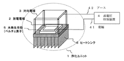
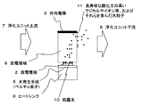
図1および図2は本発明の一実施形態における浄化装置の概略図および断面図である。なお、以下では空気などの気体について説明するが、水などの液体、固体でも同様である。 1 and 2 are a schematic view and a cross-sectional view of a purification device according to an embodiment of the present invention. In addition, although gas, such as air, is demonstrated below, it is the same also with liquids, such as water, and solid.
浄化ユニット1は、気体の流路内に配置されるものであり、放電電極2が配置され、放
電電極2の対向に対向電極3が配置されていて、放電電極2と対向電極3との間に形成される放電領域9が構成されている。7は浄化ユニット上流気流、8は浄化ユニット下流気流を示す。
The
高電圧印加装置4は、放電電極2に接続する電極(プラスまたはマイナス)41と、対向電極3に接続するアース電極42とを有し、放電電極2と対向電極3との間に、放電を発生させ得る高電圧を印加するように構成されている。この高電圧印加装置4としては、高圧トランスで昇圧するようにした電装回路などが使用される。しかし所望の高電圧を印加できるものであれば、これに限定されず使用可能である。
The high
水発生手段5は、例えばペルチェ素子など無給水で水を発生させるのもであり、放電電極2に密着させ設けておく。これにより、放電電極2が露点以下の温度になると放電電極2の表面に結露水10が発生する。例えば、温度が22℃で湿度が30%のとき、放電電極2が露点すなわち3.6℃以下の温度になると放電電極2の表面に結露水10が発生する。なお、ペルチェ素子を対向電極3に密着させ設けておいてもかまわない。
The water generating means 5 generates water without supplying water, such as a Peltier element, and is provided in close contact with the
さらに、ヒートシンク6は、水発生手段5に密着させ設けておく。例えば水発生手段5をペルチェ素子とすると、一方が冷却面であれば他方は放熱面になり、この放熱面に、ヒートシンク6を密着することにより効率よく放電電極2が露点以下の温度になる。
Furthermore, the heat sink 6 is provided in close contact with the water generating means 5. For example, if the water generating means 5 is a Peltier element, if one is a cooling surface, the other is a heat radiating surface, and the heat sink 6 is brought into close contact with the heat radiating surface, whereby the
以下、上記構成における作用を説明する。 Hereinafter, the operation of the above configuration will be described.
高電圧印加装置4によって放電電極2と対向電極3との間に高電圧を印加するとともに、水発生手段9により放電電極2に結露水10を発生させる。これにより電極間に発生させた放電と結露水10を利用し、放電領域9でラジカルやイオン等、およびそれらを含んだ微細な水粒子11を生成し、放電領域下流すなわち、浄化ユニット下流8に放出させることができる。
A high voltage is applied between the
簡略化すると例えば For example, if simplified

の反応がおこり、放電領域9の下流に、OHラジカルやイオン、H2O2ラジカルやイオン等、酸化力の高いラジカルやイオン等、およびそれらを含んだ水粒子11を豊富に生成することができる。 As a result of this reaction, downstream of the discharge region 9, OH radicals and ions, H 2 O 2 radicals and ions, etc., radicals and ions with high oxidizing power, and water particles 11 containing them may be generated in abundance. it can.
この生成されたラジカルやイオン等、およびそれらを含んだ水粒子11は酸化力が高く、微生物の外壁やタンパク質を破壊することができ、微生物は殺滅または不活化される。すなわち、生成されたOHラジカルやイオン、H2O2ラジカルやイオン等、酸化力の高いラジカルやイオン等、およびそれらを含んだ水粒子11を放電領域9の下流に放出させることにより、放出された領域を殺菌、脱臭、有害物質除去することができ、浄化される。
The generated radicals and ions and the water particles 11 containing them have high oxidizing power, can destroy the outer wall and protein of the microorganism, and the microorganism is killed or inactivated. That is, by releasing the generated OH radicals and ions, H 2
印加すべき高電圧は、効率よく放電を発生させ得る高電圧であり、放電電極2と対向電極3との間隙の大きさ、放電領域の温度湿度環境によっても異なるが、たとえば放電電極
2と対向電極3との間隙が約4mmで、温度が22℃、湿度が40%の時には、約4kV以上の高電圧が必要である。
The high voltage to be applied is a high voltage that can efficiently generate a discharge, and varies depending on the size of the gap between the
また負の高電圧を印加することによって、放電領域9でマイナスイオンを生成することができ、下流気流7としてマイナスイオンを含んだきれいな空気を供給して、リラックスできる雰囲気を提供することが可能となる。 Further, by applying a negative high voltage, negative ions can be generated in the discharge region 9, and it is possible to provide a relaxing atmosphere by supplying clean air containing negative ions as the downstream airflow 7. Become.
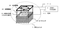
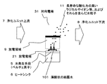
図3、図4は、突起を設けた放電電極21、さらに網状や環状の形状の対向電極31のときの概略図である。なお、突起を設けた放電電極21について、放電が効率的に可能であれば、その突起部の本数についてはなんら限定しない。これにより、突起を設けた放電電極21の突起先端で効率よく放電を発生させることができる。また、酸化力の高い水粒子11は対向電極31に阻害されることなく浄化ユニット下流8により効率よく放出させることができるとともに、浄化ユニット1のサイズを小さくすることができる。
3 and 4 are schematic views of the discharge electrode 21 provided with protrusions and the counter electrode 31 having a net shape or an annular shape. In addition, about the discharge electrode 21 which provided the protrusion, if discharge is possible efficiently, the number of the protrusion part will not be limited at all. Thereby, discharge can be efficiently generated at the protrusion tip of the discharge electrode 21 provided with the protrusion. Further, the water particles 11 having a high oxidizing power can be efficiently discharged from the purification unit downstream 8 without being inhibited by the counter electrode 31, and the size of the
また、放電電極21を親水性処理を行う。これにより、電極表面に薄膜状の結露水101が生成でき、より効率よく放電を発生させることができる。 Further, the discharge electrode 21 is subjected to hydrophilic treatment. Thereby, the thin film-shaped condensed water 101 can be produced | generated on the electrode surface, and discharge can be generated more efficiently.
また、好ましくは、放電電極21を、アルミや銅を含む材質とする。これにより、電極が露点以下に効率よく冷やされ、効率よく水を発生させることができる。さらに、放電電極21を、カーボンを含む材質とする。これにより、電極の耐久性が向上し、放電領域でさらに多量のラジカルやイオン等、およびそれらを含んだ微細な水粒子を生成し、前記放電領域下流に放出させることが長期間維持できる。 Preferably, the discharge electrode 21 is made of a material containing aluminum or copper. Thereby, an electrode is efficiently cooled below a dew point and water can be generated efficiently. Further, the discharge electrode 21 is made of a material containing carbon. This improves the durability of the electrode, a larger amount of radicals and ions in the discharge region, and generates a fine water particles containing them, wherein the discharging area released downstream can be maintained long term.
なお、本浄化装置を、例えば風量の大きい、空気清浄機や空気調和機に搭載すると、さらに浄化性能を向上させることができる。 In addition, if this purification apparatus is mounted in an air cleaner or an air conditioner having a large air volume, for example, the purification performance can be further improved.
1 浄化ユニット
2 放電電極
3 対向電極
4 高電圧印加装置
5 水発生手段
DESCRIPTION OF
Claims (5)
Priority Applications (1)
| Application Number | Priority Date | Filing Date | Title |
|---|---|---|---|
| JP2004204384A JP4075868B2 (en) | 2004-07-12 | 2004-07-12 | Purification device |
Applications Claiming Priority (1)
| Application Number | Priority Date | Filing Date | Title |
|---|---|---|---|
| JP2004204384A JP4075868B2 (en) | 2004-07-12 | 2004-07-12 | Purification device |
Publications (2)
| Publication Number | Publication Date |
|---|---|
| JP2006025816A JP2006025816A (en) | 2006-02-02 |
| JP4075868B2 true JP4075868B2 (en) | 2008-04-16 |
Family
ID=35892856
Family Applications (1)
| Application Number | Title | Priority Date | Filing Date |
|---|---|---|---|
| JP2004204384A Expired - Lifetime JP4075868B2 (en) | 2004-07-12 | 2004-07-12 | Purification device |
Country Status (1)
| Country | Link |
|---|---|
| JP (1) | JP4075868B2 (en) |
Families Citing this family (4)
| Publication number | Priority date | Publication date | Assignee | Title |
|---|---|---|---|---|
| JP2008183480A (en) * | 2007-01-26 | 2008-08-14 | Matsushita Electric Works Ltd | Electrostatic atomizer |
| JP5081031B2 (en) * | 2008-03-26 | 2012-11-21 | パナソニック株式会社 | Ion generator |
| RU2011143152A (en) * | 2009-03-26 | 2013-05-10 | Панасоник Корпорэшн | ELECTROSTATIC SPRAYING DEVICE AND METHOD FOR ITS MANUFACTURE |
| JP2010249427A (en) * | 2009-04-16 | 2010-11-04 | Mitsubishi Electric Corp | refrigerator |
Family Cites Families (7)
| Publication number | Priority date | Publication date | Assignee | Title |
|---|---|---|---|---|
| JPH043618Y2 (en) * | 1987-08-13 | 1992-02-04 | ||
| JPH06102083B2 (en) * | 1992-11-04 | 1994-12-14 | 富士工業株式会社 | Indoor air purifier using hydroxyl ion gas |
| JPH09108313A (en) * | 1995-10-24 | 1997-04-28 | Mitsubishi Electric Corp | Method and apparatus for preventing microbial reproduction |
| JP2004093019A (en) * | 2002-08-30 | 2004-03-25 | Matsushita Electric Works Ltd | Air cleaner |
| JP4625267B2 (en) * | 2004-04-08 | 2011-02-02 | パナソニック電工株式会社 | Electrostatic atomizer |
| JP2005319346A (en) * | 2004-05-06 | 2005-11-17 | Matsushita Electric Ind Co Ltd | Purification method and purification device |
| JP4706198B2 (en) * | 2004-07-16 | 2011-06-22 | パナソニック株式会社 | Air purification device |
-
2004
- 2004-07-12 JP JP2004204384A patent/JP4075868B2/en not_active Expired - Lifetime
Also Published As
| Publication number | Publication date |
|---|---|
| JP2006025816A (en) | 2006-02-02 |
Similar Documents
| Publication | Publication Date | Title |
|---|---|---|
| JP4123203B2 (en) | Air conditioner | |
| JPH07115946A (en) | Device for preventing multiplication of microorganism | |
| CN108097042A (en) | A kind of ion field arrangement for catalytic purification and method | |
| JP4089661B2 (en) | Purification device | |
| JPH09108313A (en) | Method and apparatus for preventing microbial reproduction | |
| US20240374765A1 (en) | Plasma source for hand disinfection | |
| JP2002058731A (en) | Air purifier and air conditioner equipped with ion generator | |
| JP4075869B2 (en) | Purification device | |
| KR101959660B1 (en) | Plasma and ion generating device | |
| JP4075868B2 (en) | Purification device | |
| KR20200063867A (en) | Ozone removing apparatus | |
| JP2004194930A (en) | Sterilization method and sterilization device | |
| KR100518387B1 (en) | Negative ion operating device for ac | |
| JP2005319346A (en) | Purification method and purification device | |
| KR20200082771A (en) | Plasma sterilizer with ozone abatement function | |
| JP2002319471A (en) | Ion generating element and device having the same | |
| JP2004350890A (en) | Purification method and purification device | |
| JP2005168534A (en) | Purification method and purification device | |
| JP2006269095A (en) | Plasma generation device | |
| JP2006110403A (en) | Purification device | |
| JP2005168533A (en) | Purification method and purification device | |
| JP2005164176A (en) | Purification method and purification device | |
| JP2006167190A (en) | Air purification device | |
| JP2004000606A (en) | Sterilization method, ion generator and air conditioner | |
| JP2006102347A (en) | Purification device |
Legal Events
| Date | Code | Title | Description |
|---|---|---|---|
| A621 | Written request for application examination |
Free format text: JAPANESE INTERMEDIATE CODE: A621 Effective date: 20070514 |
|
| RD01 | Notification of change of attorney |
Free format text: JAPANESE INTERMEDIATE CODE: A7421 Effective date: 20070613 |
|
| A871 | Explanation of circumstances concerning accelerated examination |
Free format text: JAPANESE INTERMEDIATE CODE: A871 Effective date: 20070905 |
|
| A975 | Report on accelerated examination |
Free format text: JAPANESE INTERMEDIATE CODE: A971005 Effective date: 20071002 |
|
| A131 | Notification of reasons for refusal |
Free format text: JAPANESE INTERMEDIATE CODE: A131 Effective date: 20071009 |
|
| A521 | Request for written amendment filed |
Free format text: JAPANESE INTERMEDIATE CODE: A523 Effective date: 20071210 |
|
| TRDD | Decision of grant or rejection written | ||
| A01 | Written decision to grant a patent or to grant a registration (utility model) |
Free format text: JAPANESE INTERMEDIATE CODE: A01 Effective date: 20080108 |
|
| A61 | First payment of annual fees (during grant procedure) |
Free format text: JAPANESE INTERMEDIATE CODE: A61 Effective date: 20080121 |
|
| R151 | Written notification of patent or utility model registration |
Ref document number: 4075868 Country of ref document: JP Free format text: JAPANESE INTERMEDIATE CODE: R151 |
|
| FPAY | Renewal fee payment (event date is renewal date of database) |
Free format text: PAYMENT UNTIL: 20110208 Year of fee payment: 3 |
|
| FPAY | Renewal fee payment (event date is renewal date of database) |
Free format text: PAYMENT UNTIL: 20120208 Year of fee payment: 4 |
|
| FPAY | Renewal fee payment (event date is renewal date of database) |
Free format text: PAYMENT UNTIL: 20130208 Year of fee payment: 5 |
|
| FPAY | Renewal fee payment (event date is renewal date of database) |
Free format text: PAYMENT UNTIL: 20130208 Year of fee payment: 5 |
|
| FPAY | Renewal fee payment (event date is renewal date of database) |
Free format text: PAYMENT UNTIL: 20140208 Year of fee payment: 6 |
|
| R154 | Certificate of patent or utility model (reissue) |
Free format text: JAPANESE INTERMEDIATE CODE: R154 |
|
| EXPY | Cancellation because of completion of term | ||
| R154 | Certificate of patent or utility model (reissue) |
Free format text: JAPANESE INTERMEDIATE CODE: R154 |