JP4074985B2 - Disc brake - Google Patents
Disc brake Download PDFInfo
- Publication number
- JP4074985B2 JP4074985B2 JP2002254290A JP2002254290A JP4074985B2 JP 4074985 B2 JP4074985 B2 JP 4074985B2 JP 2002254290 A JP2002254290 A JP 2002254290A JP 2002254290 A JP2002254290 A JP 2002254290A JP 4074985 B2 JP4074985 B2 JP 4074985B2
- Authority
- JP
- Japan
- Prior art keywords
- pad
- braking torque
- brake
- disc
- support
- Prior art date
- Legal status (The legal status is an assumption and is not a legal conclusion. Google has not performed a legal analysis and makes no representation as to the accuracy of the status listed.)
- Expired - Fee Related
Links
Images


Description
【0001】
【産業上の利用分野】
本発明は、制動トルクを直接検出できるようにしたディスクブレーキに関するものである。
【0002】
【従来の技術】
現在、自動車等のブレーキシステムにおいて、各種センサを用いて、各車輪の回転速度、車両速度、車両加速度、操舵角、車両横加速度、各車輪の制動トルク等の車両状態を検出し、コントローラによってこれらの検出に基づいて各車輪の制動力を制御することにより、アンチロック制御、トラクション制御および車両安定化制御等を行うことが可能となっている。
【0003】
従来、各車輪の制動トルクを検出する際、液圧ブレーキシステムの場合には、圧力センサによって検出した各車輪のブレーキ装置に作用する液圧からブレーキパッドの摩擦係数に基づいて間接的に制動トルクを計算するようにしている。
【0004】
しかしながら、ブレーキパッドの摩擦係数は、温度等によって大きく変化するため、実際の制動トルクを正確に計算することは困難であり、必ずしも最適な制御が行われているとはいえなかった。
【0005】
そこで、各車輪の制動トルクを正確に検出すべく、実際の制動トルクを直接的に検出する手段が種々提案されている。例えば、特許文献1および2には、ディスクブレーキのキャリアを支持するナックルに歪みセンサを取付け、制動時に生じるナックルのキャリア取付部の歪みから制動トルクを検出する技術が開示されている。
【0006】
特許文献3には、ディスクブレーキのキャリアに設けた起歪部に歪センサを取付け、制動時にキャリアに生じる歪みから制動トルクを検出する技術が開示されている。
【0007】
特許文献4には、ディスクブレーキのキャリアのブレーキパッドから制動トルクを受ける部分に荷重センサを取付け、制動時にブレーキパッドに作用する制動トルクを直接検出する技術が開示されている。
【0008】
また、特許文献5には、ディスクブレーキのキャリアを軸によって回動可能に支持し、キャリアの回動を規制するストッパ部に荷重センサを取付け、制動時にキャリアに作用する制動トルクを直接検出する技術が開示されている。
【0009】
【特許文献1】
欧州特許第1176324号明細書
【特許文献2】
特許第2736392号公報
【特許文献3】
国際特許公開第01/44676号パンフレット
【特許文献4】
特公昭50-18547号公報
【特許文献5】
特公平7-67907号公報
【0010】
【発明が解決しようとする課題】
しかしながら、上記従来の特許文献記載の技術では、次のような問題がある。特許文献1、2および3に記載されたものでは、いずれも、歪みの検出部が制動トルクを発生するディスクロータの中心からオフセットされており、ディスクロータの軸方向中心面に対して非対称となっているため、制動トルクによってキャリアに生じるモーメントの影響により、正確な制動トルクを検出しにくくなる。特許文献4に記載されたものでは、荷重センサによってブレーキパッドの荷重を直接受けるため、荷重センサの強度、耐熱性が問題となる。また、特許文献5に記載されたものでは、キャリアからの荷重を直接受ける軸および荷重センサの強度が問題となる。
【0011】
本発明は、上記の点に鑑みてなされたものであり、キャリアに生じるモーメントの影響を小さくして、制動トルクの検出精度を高めることができるディスクブレーキを提供することを目的とする。
【0012】
【課題を解決するための手段】
上記の課題を解決するために、請求項1に係る発明は、ディスクロータを挟んで両側に配置されるブレーキパッドと、該ブレーキパッドを前記ディスクロータの軸方向に沿って移動可能に支持し、非回転部に固定されるパッド支持部材とを備え、前記ブレーキパッドを前記ディスクロータに押圧するディスクブレーキにおいて、
前記パッド支持部材には、前記ブレーキパッドから制動トルクを受けるパッド受部と、該パッド受部の背部から前記ディスクロータの外周に沿って延ばされ、前記パッド支持部材の非回転部への取付部に連結されるアーム部とが設けられ、該アーム部の一部が前記ディスクロータの外周と間隔をもって延びて前記ディスクロータの軸方向中心に配置された支持部となっており、該支持部には、該支持部の変位または歪みを検出する検出手段が設けられていることを特徴とする。
このように構成したことにより、制動トルクに応じて支持部に変位又は歪みが生じ、この変位又は歪みを検出手段によって検出することによって、直接的に制動トルクを得ることができる。このとき、支持部をディスクロータの外周の軸方向中心に配置したので、パッド支持部材に生じるモーメントの影響を受けることなく、制動トルクを検出することができる。
請求項2に係る発明は、上記請求項1の構成において、前記支持部は、前記ディスクロータの外周に沿って円弧状に形成されていることを特徴とする。
このように構成したことにより、パッド受部に作用した制動トルクは、円弧状の支持部を介してパッド支持部材の非回転部への取付部に伝達される。
【0013】
【発明の実施の形態】
以下、本発明の実施形態を図面に基づいて詳細に説明する。
本発明の第1実施形態について、図1乃至図4を参照して説明する。本実施形態に係るディスクブレーキは、キャリパ浮動型ディスクブレーキであり、図1乃至図4には、その要部であるディスクロータ1、キャリア2および制動トルク検出アーム3,4のみが示してある。
【0014】
ディスクロータ1は、摩擦面を形成したロータ部5の一側に、車軸のハブ(図示せず)が連結されるハブ取付部6を突出させたハット形状となっている。また、ディスクロータ1は、ベンチレーテッドタイプであり、ロータ部5には複数の通風口7が放射状に設けられている。
【0015】
キャリア2は、ディスクロータ1のロータ部5の外周部を跨ぐ一対のパッド支持部8,9を有している。パッド支持部8,9(パッド支持部材)には、ディスクロータ1のロータ部5の外側(ハブ取付部6側)に配置されたアウタブレーキパッド(図示せず) の両端部が当接するパッド受部8A,9Aおよびロータ部2の内側(ハブ取付部6の反対側)に配置されたインナブレーキパッド(図示せず)の両端部が当接するパッド受部8B,9Bが形成されており、パッド受部8A,8B,9A,9Bには、アウタ及びインナブレーキパッドをディスクロータ1の軸方向に沿って摺動可能に案内する矩形の溝部8C,8D,9C,9Dが形成されている。
【0016】
パッド支持部8,9は、パッド受部8A,8B,9A,9Bの背部から延出されたアーム部11,12を介して、ディスクロータ1の内側に配置された取付部13によって互いに連結されている。アーム部11,12は、パッド支持部8,9のパッド受部8A,8B,9A,9Bの背部からディスクロータ1の外周の軸方向中心(図4に示す一点鎖線C)に沿って円弧状に延ばされた支持部11A,12Aを有し、さらに、ディスクロータ1の内側へ折曲され、ディスクロータ1のほぼ径方向に沿って延ばされて、取付部13の両端部に結合されている。取付部13の両端部には、ボス部14,15が形成されており、ボス部14,15にボルト(図示せず)を挿通して、キャリア2がディスクロータ1のハブ取付部6の内側に配置されたナックル等の車体の非回転部(図示せず)に取付けられる。なお、本実施形態においては、支持部11A,12Aの太さは、ほぼ均一であり、その幅は、パッド支持部8,9のディスクロータ軸方向長さの1/4程度となっている。また、支持部11A,12Aは、ディスクロータ1の外周に沿って円弧状に形成されており、ディスクロータ1の外周から一定の間隔をもって延ばされている。
【0017】
パッド支持部8,9には、ディスクロータ1の周方向においてパッド受部8A,8B,9A,9Bと支持部11A,12Aとの間にピンガイド16,17が一体に形成されており、キャリパ側に固定されたスライドピン(図示せず)をピンガイド16,17に摺動可能に挿通させて、キャリパをディスクロータ1の軸方向に沿って移動可能に案内する。
【0018】
制動トルク検出アーム3,4は、一端部に形成された取付ボス部18,19がキャリア2の取付部13と共締めされて非回転部に固定されており、他端部がディスクロータ1の外周部に配置されたアーム部11,12の支持部11A,12Aの後端部に対向する位置まで延ばされている。制動トルク検出アーム3,4の先端部に変位センサ20,21が取付けられ、その検出子が支持部11A,12Aの後端部に当接されている。そして、変位センサ20,21によって、支持部11A,12Aのディスクロータ1の周方向に沿った変位を検出するようになっている。なお、変位センサ20,21は、制動トルクによる支持部11A,12Aの僅かな変位を電気信号として検出可能なものであり、例えば、差動トランス式変位センサ、光波干渉式変位センサ、静電容量式変位センサ、導電ゴム式変位センサ等を使用することができる。
【0019】
キャリア2のピンガイド16,17にスライドピンを挿入してキャリパを装着し、パッド支持部8,9にアウタおよびインナブレーキパッドを装着し、そして、キャリア2および制動トルク検出アーム3,4をボルトによってナックル等の車体の非回転部に取付ける。
【0020】
以上のように構成した本実施形態の作用について次に説明する。
キャリパによってアウタおよびインナブレーキパッドをディスクロータ1のロータ部5の摩擦面に押付けて制動力を発生させる。ディスクロータ1の回転方向が図3中に矢印で示す方向(車両前進時)である場合、制動トルクによってアウタ及びインナブレーキパッドがディスクロータ1に引きずられて、キャリア2のパッド受部8A,8Bを押圧する。これにより、アーム部11が僅かに弾性変形して支持部11Aがディスクロータ1の周方向に沿って変位する。この変位を制動トルク検出アーム3に取付けられた変位センサ20によって検出する。アーム部11の弾性変形量は、制動トルクの大きさに比例するので、支持部11Aの変位を検出することによって、制動トルクを正確に計算することができる。
【0021】
ディスクロータ1の回転方向が上記の反対方向(車両後退時)の場合は、アウタパッド及びインナパッドがキャリア2のパッド受部9A,9Bに押付けられるので、上記とは反対側の制動トルク検出アーム4に取付けられた変位センサ21によって、アーム部12の支持部12Aの変位を検出することにより、制動トルクを計算することができる。
【0022】
この場合、制動トルクを受けるパッド受部8A,8B,9A,9Bを有するパッド支持部8,9がディスクロータ1の外周でディスクロータ1の軸方向中心に配置された支持部11A,12Aと連結していることにより、制動トルクによるキャリア2の撓みによって支持部11A,12Aにモーメントが生じないので、支持部11A,12Aの変位を検出することでモーメントの影響を考慮することなく制動トルクを正確に計算することができる。
【0023】
また、ピンガイド16,17をディスクロータ1の周方向においてパッド受部8A,8B,9A,9Bと支持部11A,12Aとの間に配置することにより、キャリパを介してスライドピンにかかる制動トルクの成分を同時に検出することができる。
【0024】
次に、本発明の第2実施形態について、図5乃至図8を参照して説明する。なお、上記第1実施形態のものに対して、同様の部分には同一の符号を付し、異なる部分についてのみ詳細に説明する。
【0025】
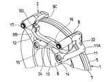
図5乃至図8に示すように、第2実施形態に係るディスクブレーキでは、制動トルク検出アーム3,4が省略されており、代りに、キャリア2の一方の支持部11Aに歪みセンサ22が装着されている。歪みセンサ22は、制動トルクによる支持部11Aの僅かな変形を電気信号として検出可能なものであり、例えば歪みゲージを使用することができる。
【0026】
また、キャリア2のパッド支持部8,9のパッド受部8Aとパッド受部9Aおよびパッド受部8Bとパッド受部9Bが、それぞれアウタビーム23及びインナビーム24によって互いに連結されている。
【0027】
このように構成したことにより、車両前進時における制動時には、ディスクロータ1に引きずられるアウタ及びインナパッドによってパッド受部8A,8Bが押圧され、アーム部11の支持部11Aに圧縮力が作用して、支持部11Aが僅かに弾性変形する。この支持部11Aの変形量を歪みセンサ22によって検出する。支持部11Aの変形量は、制動トルクの大きさに比例するので、支持部11Aの変形量を検出することによって、制動トルクを正確に計算することができる。
【0028】
車両後退時における制動時には、アウタ及びインナパッドによってパッド受部9A,9Bが押圧されるが、この力がアウタビーム23及びインナビーム24によって反対側のパッド受部8A,8Bに伝達されて、支持部11Aに引張力を作用させ、支持部11Aが弾性変形する。支持部11Aの変形量は、制動トルクの大きさに比例するので、支持部11Aの変形量を歪みセンサ22によって検出することにより、制動トルクを正確に計算することができる。
【0029】
このように、アウタビーム23及びインナビーム24によってパッド受部8A,9Aおよびパッド受部8B,9Bを互いに連結することにより、1つの歪みセンサ22によって前進時及び後退時の制動トルクを検出することができる。
【0030】
上記第1実施形態と同様、キャリア2の撓みによって支持部11A,12Aにモーメントが生じないので、制動トルクによってキャリア2に生じるモーメントの影響を受けることなく制動トルクを正確に計算することができる。
【0031】
なお、アウタビーム23及びインナビーム24を省略し、歪みセンサを支持アーム11,12の両方に設けて、前進時及び後退時の制動トルクを別々に検出することもできる。また、上記第1実施形態においても、パッド受部8A,9Aおよびパッド受部8B,9Bを互いに連結するアウタビーム23及びインナビーム24を設けることにより、一方の制動トルク検出アーム3の変位センサ20によって前進時及び後退時両方の制動トルクを検出することができ、他方の制動トルク検出アーム4及び変位センサ21を省略することができる。
【0032】
上記第1及び第2実施形態において、支持部11A,12Aの太さは、均一でなくてもよく、例えばパッド支持部8,9側を太く又は細くしたテーパ形状とすることができ、この場合、第2実施形態においては、支持部11A,12Aの細くした部分に歪みセンサ22を取付けることにより、荷重に対する変形量が大きくなり、小さな制動トルクを検出しやすくなる。支持部11A,12Aは、さらに太くすることもでき、例えばパッド支持部8,9のディスクロータ軸方向長さとほぼ同じ幅とすることもできる。また、支持部11A,12Aとディスクロータ1の外周との間隔は、適宜設定することができ、上記第1実施形態においては、この間隔をホイールと干渉しない範囲で大きくすることにより、荷重に対する支持部11A,12Aの変位量が大きくなり、小さな制動トルクを検出しやすくなる。
【0033】
上記第2実施形態を適用したキャリパ浮動型ディスクブレーキの全体図を図9に示す。図9において、符号25は電動モータによってパッドを押圧するキャリパ、26はキャリパ25を案内するスライドピンを示す。
【0034】
また、上記第2実施形態を対向ピストン型ディスクブレーキに適用した場合の全体図を図10に示す。図10に示すように、アウタブレーキパッド及びインナブレーキパッドをそれぞれ押圧する2対の対向するピストンを有するキャリパ27がキャリア2のパッド支持部8,9と一体に形成されている。この場合も、上記と同様、前進時及び後退時の制動トルクを歪みセンサ22によって検出することができる。
【0035】
なお、図9および図10に示すキャリパは、いずれも上記第2実施形態のものと同様、上記第1実施形態のものにも組合わせることができる。
【0036】
【発明の効果】
以上、詳述したように、請求項1の発明に係るディスクブレーキによれば、ディスクロータの外周から一定の間隔をもって延びて前記ディスクロータの軸方向中心に配置した支持部に生じる変位又は歪みを検出することにより、パッド支持部材に生じるモーメントの影響を受けることなく、制動トルクを検出することができる。
請求項2の発明に係るディスクブレーキによれば、パッド受部に作用した制動トルクが円弧状の支持部を介してパッド支持部材の非回転部への取付部に伝達される。
【図面の簡単な説明】
【図1】本発明の第1実施形態に係るディスクブレーキの要部を示す斜視図である。
【図2】図1に示すディスクブレーキの要部の平面図である。
【図3】図1に示すディスクブレーキの要部の正面図である。
【図4】図1に示すディスクブレーキの要部の側面図である。
【図5】本発明の第2実施形態に係るディスクブレーキの要部を示す斜視図である。
【図6】図5に示すディスクブレーキの要部の平面図である。
【図7】図5に示すディスクブレーキの要部の正面図である。
【図8】図5に示すディスクブレーキの要部の側面図である。
【図9】本発明の第2実施形態を適用したキャリパ浮動形ディスクブレーキの斜視図である。
【図10】本発明の第2実施形態を適用した対向ピストン型ディスクブレーキの斜視図である。
【符号の説明】
1 ディスクロータ
2 キャリア
8A,8B,9A,9B パッド受部
11A,12A 支持部
13 取付部
20 変位センサ(検出手段)
22 歪みセンサ(検出手段)
25,27 キャリパ[0001]
[Industrial application fields]
The present invention relates to a disc brake that can directly detect braking torque.
[0002]
[Prior art]
Currently, in a brake system such as an automobile, various sensors are used to detect vehicle conditions such as the rotational speed of each wheel, vehicle speed, vehicle acceleration, steering angle, vehicle lateral acceleration, braking torque of each wheel, etc. By controlling the braking force of each wheel based on this detection, antilock control, traction control, vehicle stabilization control, and the like can be performed.
[0003]
Conventionally, when detecting the braking torque of each wheel, in the case of a hydraulic brake system, the braking torque is indirectly determined based on the friction coefficient of the brake pad from the hydraulic pressure acting on the brake device of each wheel detected by the pressure sensor. I am trying to calculate.
[0004]
However, since the friction coefficient of the brake pad varies greatly depending on the temperature or the like, it is difficult to accurately calculate the actual braking torque, and it cannot be said that optimal control is necessarily performed.
[0005]
Therefore, various means for directly detecting the actual braking torque have been proposed in order to accurately detect the braking torque of each wheel. For example,
[0006]
[0007]
Patent Document 4 discloses a technique in which a load sensor is attached to a portion of a disc brake carrier that receives a braking torque from a brake pad, and the braking torque acting on the brake pad during braking is directly detected.
[0008]
[0009]
[Patent Document 1]
European Patent No. 1176324 [Patent Document 2]
Japanese Patent No. 2736392 [Patent Document 3]
International Patent Publication No. 01/44676 Pamphlet [Patent Document 4]
Japanese Patent Publication No. 50-18547 [Patent Document 5]
Japanese Examined Patent Publication No. 7-67907 [0010]
[Problems to be solved by the invention]
However, the conventional techniques described in the above patent documents have the following problems. In all of
[0011]
The present invention has been made in view of the above points, and an object of the present invention is to provide a disc brake capable of reducing the influence of a moment generated on a carrier and improving the detection accuracy of a braking torque.
[0012]
[Means for Solving the Problems]
In order to solve the above-mentioned problem, the invention according to
Wherein the pad supporting member, wherein the brake pad and the pad receiving portion for receiving the braking torque, extended from the back of the pad receiving portion along the outer periphery of the disc rotor, attached to the non-rotating portion of the pad supporting member an arm portion connected is provided in the section, said portion of the arm portion is a support disposed in the axial center of the disc rotor extends with an outer periphery and spacing of the disc rotor, the support portion to is characterized in that the detection means for detecting the displacement or strain of the supporting portion is eclipsed set.
With such a configuration, displacement or distortion occurs in the support portion according to the braking torque, and the braking torque can be obtained directly by detecting the displacement or distortion by the detecting means. At this time, since the support portion is arranged at the axial center of the outer periphery of the disk rotor, the braking torque can be detected without being affected by the moment generated in the pad support member.
According to a second aspect of the present invention, in the configuration of the first aspect, the support portion is formed in an arc shape along the outer periphery of the disk rotor .
With this configuration, the braking torque applied to the pad receiving portion is transmitted to the attachment portion of the pad support member to the non-rotating portion via the arc-shaped support portion.
[0013]
DETAILED DESCRIPTION OF THE INVENTION
Hereinafter, embodiments of the present invention will be described in detail with reference to the drawings.
A first embodiment of the present invention will be described with reference to FIGS. The disc brake according to the present embodiment is a caliper floating disc brake, and FIGS. 1 to 4 show only the
[0014]
The
[0015]
The
[0016]
The pad support
[0017]
In the
[0018]
The braking
[0019]
Insert the slide pin into the pin guides 16 and 17 of the
[0020]
The operation of the present embodiment configured as described above will be described next.
The caliper presses the outer and inner brake pads against the friction surface of the
[0021]
When the rotation direction of the
[0022]
Coupling this case, the
[0023]
Also, by placing the pin guides 16 and 17 between the
[0024]
Next, a second embodiment of the present invention will be described with reference to FIGS. In addition, the same code | symbol is attached | subjected to the same part with respect to the said 1st Embodiment, and only a different part is demonstrated in detail.
[0025]
As shown in FIGS. 5 to 8, in the disc brake according to the second embodiment, the braking
[0026]
Further, the
[0027]
With this configuration, the
[0028]
During braking when the vehicle is reverse, the
[0029]
In this way, by connecting the
[0030]
As in the first embodiment, since no moment is generated in the
[0031]
Note that the
[0032]
In the first and second embodiments, the thickness of the
[0033]
FIG. 9 shows an overall view of a caliper floating disc brake to which the second embodiment is applied. In FIG. 9,
[0034]
FIG. 10 shows an overall view when the second embodiment is applied to an opposed piston type disc brake. As shown in FIG. 10, a
[0035]
Note that the calipers shown in FIGS. 9 and 10 can be combined with those of the first embodiment as well as those of the second embodiment.
[0036]
【The invention's effect】
As described above in detail, according to the disc brake according to the first aspect of the present invention, the displacement or distortion generated in the support portion that extends from the outer periphery of the disc rotor with a constant interval and is arranged at the center in the axial direction of the disc rotor. By detecting, the braking torque can be detected without being affected by the moment generated in the pad support member.
According to the disc brake of the second aspect of the present invention, the braking torque acting on the pad receiving portion is transmitted to the attachment portion of the pad support member to the non-rotating portion via the arc-shaped support portion.
[Brief description of the drawings]
FIG. 1 is a perspective view showing a main part of a disc brake according to a first embodiment of the present invention.
FIG. 2 is a plan view of the main part of the disc brake shown in FIG.
FIG. 3 is a front view of a main part of the disc brake shown in FIG.
4 is a side view of a main part of the disc brake shown in FIG. 1. FIG.
FIG. 5 is a perspective view showing a main part of a disc brake according to a second embodiment of the present invention.
6 is a plan view of the main part of the disc brake shown in FIG. 5. FIG.
7 is a front view of the main part of the disc brake shown in FIG. 5. FIG.
8 is a side view of the main part of the disc brake shown in FIG.
FIG. 9 is a perspective view of a caliper floating disc brake to which a second embodiment of the present invention is applied.
FIG. 10 is a perspective view of an opposed piston type disc brake to which a second embodiment of the present invention is applied.
[Explanation of symbols]
1 Disc rotor
2 Career
8A, 8B, 9A, 9B Pad receiving part
11A, 12A support
13 Mounting part
20 Displacement sensor (detection means)
22 Strain sensor (detection means)
25,27 Caliper
Claims (2)
前記パッド支持部材には、前記ブレーキパッドから制動トルクを受けるパッド受部と、該パッド受部の背部から前記ディスクロータの外周に沿って延ばされ、前記パッド支持部材の非回転部への取付部に連結されるアーム部とが設けられ、該アーム部の一部が前記ディスクロータの外周と間隔をもって延びて前記ディスクロータの軸方向中心に配置された支持部となっており、該支持部には、該支持部の変位または歪みを検出する検出手段が設けられていることを特徴とするディスクブレーキ。A brake pad disposed on both sides of the disc rotor; and a pad support member that supports the brake pad so as to be movable along the axial direction of the disc rotor and is fixed to a non-rotating portion. In the disc brake that presses the disc rotor,
Wherein the pad supporting member, wherein the brake pad and the pad receiving portion for receiving the braking torque, extended from the back of the pad receiving portion along the outer periphery of the disc rotor, attached to the non-rotating portion of the pad supporting member an arm portion connected is provided in the section, said portion of the arm portion is a support disposed in the axial center of the disc rotor extends with an outer periphery and spacing of the disc rotor, the support portion the disc brake, wherein a detection means for detecting the displacement or strain of the supporting portion is eclipsed set.
Priority Applications (1)
| Application Number | Priority Date | Filing Date | Title |
|---|---|---|---|
| JP2002254290A JP4074985B2 (en) | 2002-08-30 | 2002-08-30 | Disc brake |
Applications Claiming Priority (1)
| Application Number | Priority Date | Filing Date | Title |
|---|---|---|---|
| JP2002254290A JP4074985B2 (en) | 2002-08-30 | 2002-08-30 | Disc brake |
Publications (3)
| Publication Number | Publication Date |
|---|---|
| JP2004092770A JP2004092770A (en) | 2004-03-25 |
| JP2004092770A5 JP2004092770A5 (en) | 2005-10-13 |
| JP4074985B2 true JP4074985B2 (en) | 2008-04-16 |
Family
ID=32060086
Family Applications (1)
| Application Number | Title | Priority Date | Filing Date |
|---|---|---|---|
| JP2002254290A Expired - Fee Related JP4074985B2 (en) | 2002-08-30 | 2002-08-30 | Disc brake |
Country Status (1)
| Country | Link |
|---|---|
| JP (1) | JP4074985B2 (en) |
Families Citing this family (7)
| Publication number | Priority date | Publication date | Assignee | Title |
|---|---|---|---|---|
| JP4620074B2 (en) * | 2007-03-29 | 2011-01-26 | 本田技研工業株式会社 | Brake force detection device |
| JP4769674B2 (en) * | 2006-09-22 | 2011-09-07 | 本田技研工業株式会社 | Brake force detection device |
| JP2008082894A (en) * | 2006-09-27 | 2008-04-10 | Honda Motor Co Ltd | Braking force detection device |
| JP4908998B2 (en) * | 2006-09-28 | 2012-04-04 | 本田技研工業株式会社 | Brake force detection device |
| JP4931537B2 (en) * | 2006-09-29 | 2012-05-16 | Ntn株式会社 | Wheel bearing device with in-wheel motor built-in sensor |
| JP4620073B2 (en) * | 2007-03-29 | 2011-01-26 | 本田技研工業株式会社 | Brake force detection device |
| IT201700075649A1 (en) * | 2017-07-05 | 2019-01-05 | Freni Brembo Spa | SET OF CALIPER AND SUPPORT AND METHOD |
-
2002
- 2002-08-30 JP JP2002254290A patent/JP4074985B2/en not_active Expired - Fee Related
Also Published As
| Publication number | Publication date |
|---|---|
| JP2004092770A (en) | 2004-03-25 |
Similar Documents
| Publication | Publication Date | Title |
|---|---|---|
| JP4773916B2 (en) | Brake force detection device | |
| JP5110854B2 (en) | Wheel bearing device with in-wheel motor built-in sensor | |
| US7813860B2 (en) | Brake force detecting device | |
| US20030111305A1 (en) | Wheel brake caliper with integral brake pad torque sensing | |
| JP2010270788A (en) | Disc brake | |
| JP4074985B2 (en) | Disc brake | |
| KR20050092753A (en) | Hub unit with sensor | |
| JP4908998B2 (en) | Brake force detection device | |
| JP4620074B2 (en) | Brake force detection device | |
| EP3649366B1 (en) | Caliper and support assembly and caliper deformation detection method | |
| JP3928149B2 (en) | Electric disc brake | |
| JPH11141584A (en) | Brake torque measuring device | |
| JP4584137B2 (en) | Brake force detection device | |
| JP4769674B2 (en) | Brake force detection device | |
| JP5908243B2 (en) | Bearing device for wheels with sensor | |
| JP3158013B2 (en) | Drum brake braking torque detector | |
| JP4620073B2 (en) | Brake force detection device | |
| JP2008076360A (en) | Braking force detection device | |
| JP2008082894A (en) | Braking force detection device | |
| JP2008020354A (en) | Instrument for measuring driving shaft torque and acting force between road surface and tire | |
| JP4989173B2 (en) | Strain detection device for unsprung member of vehicle | |
| WO2023100071A1 (en) | "caliper and support assembly, and method" | |
| JPH0735633A (en) | Measuring device for damping force | |
| JP2022040741A (en) | Vehicular disk brake | |
| JP2004124970A (en) | Disk brake |
Legal Events
| Date | Code | Title | Description |
|---|---|---|---|
| A711 | Notification of change in applicant |
Free format text: JAPANESE INTERMEDIATE CODE: A712 Effective date: 20041129 |
|
| A521 | Written amendment |
Free format text: JAPANESE INTERMEDIATE CODE: A523 Effective date: 20050608 |
|
| A621 | Written request for application examination |
Free format text: JAPANESE INTERMEDIATE CODE: A621 Effective date: 20050608 |
|
| A131 | Notification of reasons for refusal |
Free format text: JAPANESE INTERMEDIATE CODE: A131 Effective date: 20070418 |
|
| A977 | Report on retrieval |
Free format text: JAPANESE INTERMEDIATE CODE: A971007 Effective date: 20070420 |
|
| A521 | Written amendment |
Free format text: JAPANESE INTERMEDIATE CODE: A523 Effective date: 20070618 |
|
| TRDD | Decision of grant or rejection written | ||
| A01 | Written decision to grant a patent or to grant a registration (utility model) |
Free format text: JAPANESE INTERMEDIATE CODE: A01 Effective date: 20080109 |
|
| A61 | First payment of annual fees (during grant procedure) |
Free format text: JAPANESE INTERMEDIATE CODE: A61 Effective date: 20080117 |
|
| R150 | Certificate of patent or registration of utility model |
Ref document number: 4074985 Country of ref document: JP Free format text: JAPANESE INTERMEDIATE CODE: R150 Free format text: JAPANESE INTERMEDIATE CODE: R150 |
|
| FPAY | Renewal fee payment (event date is renewal date of database) |
Free format text: PAYMENT UNTIL: 20110208 Year of fee payment: 3 |
|
| S111 | Request for change of ownership or part of ownership |
Free format text: JAPANESE INTERMEDIATE CODE: R313111 |
|
| FPAY | Renewal fee payment (event date is renewal date of database) |
Free format text: PAYMENT UNTIL: 20110208 Year of fee payment: 3 |
|
| R350 | Written notification of registration of transfer |
Free format text: JAPANESE INTERMEDIATE CODE: R350 |
|
| FPAY | Renewal fee payment (event date is renewal date of database) |
Free format text: PAYMENT UNTIL: 20110208 Year of fee payment: 3 |
|
| FPAY | Renewal fee payment (event date is renewal date of database) |
Free format text: PAYMENT UNTIL: 20120208 Year of fee payment: 4 |
|
| FPAY | Renewal fee payment (event date is renewal date of database) |
Free format text: PAYMENT UNTIL: 20130208 Year of fee payment: 5 |
|
| FPAY | Renewal fee payment (event date is renewal date of database) |
Free format text: PAYMENT UNTIL: 20130208 Year of fee payment: 5 |
|
| FPAY | Renewal fee payment (event date is renewal date of database) |
Free format text: PAYMENT UNTIL: 20130208 Year of fee payment: 5 |
|
| FPAY | Renewal fee payment (event date is renewal date of database) |
Free format text: PAYMENT UNTIL: 20140208 Year of fee payment: 6 |
|
| LAPS | Cancellation because of no payment of annual fees |