JP4072215B2 - Image processing apparatus, control method therefor, and image processing system - Google Patents
Image processing apparatus, control method therefor, and image processing system Download PDFInfo
- Publication number
- JP4072215B2 JP4072215B2 JP03088597A JP3088597A JP4072215B2 JP 4072215 B2 JP4072215 B2 JP 4072215B2 JP 03088597 A JP03088597 A JP 03088597A JP 3088597 A JP3088597 A JP 3088597A JP 4072215 B2 JP4072215 B2 JP 4072215B2
- Authority
- JP
- Japan
- Prior art keywords
- image data
- printer
- image processing
- node
- unit
- Prior art date
- Legal status (The legal status is an assumption and is not a legal conclusion. Google has not performed a legal analysis and makes no representation as to the accuracy of the status listed.)
- Expired - Fee Related
Links
Images


Description
【0001】
【発明の属する技術分野】
本発明は、入力された画像データに処理を施しプリンタに出力する画像処理装置及びその制御方法、画像処理システムに関するものである。
【0002】
【従来の技術】
従来、デジタルカメラで撮影された画像データは、パーソナルへと送信され、画像データの出力はパーソナルコンピュータと接続されているプリンタにより行われていた。しかしながら、パソコンユーザーでないユーザーにもデジタルカメの使用を可能とするために、デジタルカメラとプリンタを直接接続可能とし、画像データに基づく画像を記録することができる画像処理システムが開発されている。
【0003】
一般的に、デジタルカメラには撮影した画像に基づく画像データを記憶するための記憶媒体の記憶容量に制限がある。そのため、その記憶媒体にできるだけ多くの画像データを記憶できるようにするため、画像データをJPEG圧縮して記憶媒体に記憶する。このようなJPEG圧縮された画像データを、デジタルカメラと直接接続されたプリンタによる記録(ダイレクトプリント)を行うためには、デジタルカメラあるいはプリンタにJPEG圧縮された画像データをJPEG解凍して得られる画像データ量分の記憶容量を持つ記憶媒体を必要とする。現在、このダイレクトプリントを実現している画像処理システムのプリンタは、A6サイズのため、1枚の記録媒体に記録を行う記録動作でA6サイズの画像データ複数分を記録することはない。そのため、A6サイズの画像データ分の記憶容量を持つ記憶媒体(バッファメモリ)があれば実現可能である。しかし、例えば、図1のように、A4サイズの記録媒体上にプリンタの記録ヘッドの走査方向にA、B、Cの3つの画像を記録する場合は、記録ヘッドの1走査で記録可能な画素数が限定されているため、1回目の記録ヘッドの走査では、バッファメモリに図1中のA1、B1、C1の部分に対応する画像データを記憶、2回目の記録ヘッドの走査では図1中のA2、B2、C2の部分といったように、各記録媒体の記録領域に対応する画像データを順次バッファメモリに記憶していけば良い。
【0004】
【発明が解決しようとする課題】
しかしながら、上記従来の画像処理システムにおいて、上記のような記録を実現するためには、デジタルカメラあるいはプリンタにJPEG圧縮されたA4サイズのA、B、Cの画像データをJPEG解凍した画像データ3つ分のバッファメモリを持つことで可能となるが、これはコスト等の問題から実現は困難である。
【0005】
また、デジタルカメラあるいはプリンタにJPEG圧縮されたA4サイズの画像データをJPEG解凍した画像データ1つ分のバッファメモリを持ち、Aの画像データをJPEG解凍、Aの画像データの内A1部分の画像データのバッファメモリへの書き込み、Bの画像データをJPEG解凍、Bの画像データの内B1部分の画像データのバッファメモリへの書き込み、Cの画像データのJPEG解凍、Cの画像データの内C1部分の画像データのバッファメモリへの書き込み、1回目の記録ヘッドの走査、Aの画像データをJPEG解凍、Aの画像データの内A2部分の画像データのバッファメモリへの書き込み、Bの画像データをJPEG解凍、Bの画像データの内B2部分の画像データのバッファメモリへの書き込み、Cの画像データのJPEG解凍、Cの画像データの内C2部分の画像データのバッファメモリへの書き込み、2回目の記録ヘッドの走査というような記録を行うことで、バッファメモリを節約することもできるが、JPEG圧縮された画像データのJPEG解凍する回数が増えるため、記録速度が低下するという問題が発生する。
【0006】
本発明は上記の問題点に鑑みてなされたものであり、コストを上げることなく、トータルスループットを向上することができる画像処理装置及びその制御方法、画像処理システムを提供することを目的とする。
【0007】
【課題を解決するための手段】
上記の目的を解決するための本発明による画像処理装置は以下の構成を備える。即ち、 入力された画像データに処理を施しプリンタに出力する画像処理装置であって、
前記プリンタと相互に通信する通信手段と、
前記通信手段を介して、前記プリンタの画像データの出力単位を示す出力単位情報を該プリンタより受信する受信手段と、
前記受信手段で受信した出力単位情報に基づいて、前記入力された画像データを分割し圧縮する圧縮手段と、
前記圧縮手段で圧縮された画像データを該プリンタへ送信する送信手段と
を備える。
【0008】
また、好ましくは、前記圧縮手段は、圧縮した画像データを記憶する記憶手段を
備える。
また、好ましくは、前記出力単位及び前記出力装置の出力設定に応じて前記記憶手段に記憶された画像データを、前記通信手段を介して該出力装置へ送信するまた、好ましくは、前記出力設定は、少なくとも出力する画像の拡大/縮小率、画像サイズに関する設定を含む。
【0009】
また、好ましくは、前記圧縮手段は、前記入力された画像データを所定単位で分割し圧縮する。
また、好ましくは、前記所定単位は、8の倍数の画素数である。
前記圧縮手段は、前記入力された画像データのピクセル方向あるいはライン方向の少なくとも一方に対し、該入力された画像データを前記8の倍数の画素数毎に分割し圧縮する。
【0010】
また、好ましくは、前記通信手段は、IEEE1394シリアルバスである。
上記の目的を達成するための本発明による画像処理装置の制御方法は以下の構成を備える、即ち、
入力された画像データに処理を施しプリンタに出力する画像処理装置の制御方法であって、
前記プリンタの画像データの出力単位を示す出力単位情報を該プリンタより受信する受信工程と、
前記受信工程で受信した出力単位情報に基づいて、前記入力された画像データを分割し圧縮する圧縮工程と、
前記圧縮工程で圧縮された画像データを該プリンタへ送信する送信工程と
を備える。
【0011】
上記の目的を達成するための本発明による画像処理システムは以下の構成を備える。即ち、
入力された画像データに処理を施す画像処理装置と、該画像処理装置で処理された画像データに基づく画像を出力するプリンタを有する画像処理システムであって、
前記画像処理装置と前記プリンタとで相互に通信する通信手段と、
前記通信手段を介して、前記プリンタの画像データの出力単位を示す出力単位情報を前記画像処理装置へ転送する第1転送手段と、
前記通知手段で通知された出力単位情報に基づいて、前記入力された画像データを分割し圧縮する圧縮手段と、
前記通信手段を介して、前記出力単位及び前記プリンタの出力設定に応じて前記圧縮手段で圧縮された画像データを該プリンタへ転送する第2転送手段と
を備える。
【0013】
【発明の実施の形態】
以下の実施形態では、デジタルカメラとプリンタとの接続にデジタルインターフェース(DーI/F)を用いた例を説明するが、これに先立ち、本実施形態で採用可能なDーI/Fの代表技術として、IEEE1394を説明する。
《IEEE1394の技術の概要》
民生用デジタルVCRやDVDプレーヤの登場に伴なって、ビデオデータやオーディオデータなどを通信するために、リアルタイムで、かつ高情報量のデータ転送のサポートが必要になっている。こういったビデオデータやオーディオデータをリアルタイムで転送し、パソコン(PC)に取り込んだり、またはその他のデジタル機器に転送を行なうには、必要な転送機能を備えた高速データ転送可能なインタフェースが必要になってくる。そういった観点から開発されたインタフェースが、IEEE1394−1995(HighPerformance Serial Bus、以下1394シリアルバスという)である。
【0014】
図11は、1394シリアルバスを用いて構成されるネットワーク・システムの構成例を示す図である。このシステムは機器A,B,C,D,E,F,G,Hを備えており、A−B間、A−C間、B−D間、D−E間、C−F間、C−G間、及びC−H間はそれぞれ1394シリアルバスのツイスト・ペア・ケーブルで接続されている。これらの機器A〜Hは、例えばパソコン、デジタルVTR、DVD、デジタルカメラ、ハードディスク、モニタ、チューナー等である。
【0015】
各機器間の接続方式は、ディジーチェーン方式とノード分岐方式とを混在可能としたものであり、自由度の高い接続が可能である。また、各機器は各自固有のIDを有し、それぞれが認識し合うことによって1394シリアルバスで接続された範囲において、1つのネットワークを構成している。各デジタル機器間をそれぞれ1本の1394シリアルバスケーブルで順次接続するだけで、それぞれの機器が中継の役割を行い、全体として1つのネットワークを構成するものである。また、1394シリアルバスはPlug&Play機能を有し、ケーブルを機器に接続した時点で自動的に機器の認識や接続状況などを認識する機能を有している。
【0016】
また、図11に示したようなシステムにおいて、ネットワークからある機器が削除されたり、または新たに追加されたときなどには、自動的にバスリセットを行い、それまでのネットワーク構成をリセットしてから、新たなネットワークの再構築を行なう。この機能によって、その時々のネットワークの構成を常時設定、認識することができる。
【0017】
またデータ転送速度は、100/200/400Mbpsを備えており、上位の転送速度を持つ機器が下位の転送速度をサポートし、互換をとるようになっている。データ転送モードとしては、コントロール信号などの非同期データ(Asynchronousデータ:以下Asyncデータという)を転送するAsynchronous転送モードとリアルタイムなビデオデータやオーディオデータ等の同期データ(Isochronousデータ:以下Isoデータという)を転送するIsochronous転送モードがある。このAsyncデータとIsoデータは、各サイクル(通常1サイクル125μs)の中において、サイクル開始を示すサイクル・スタート・パケット(CSP)を転送した後、Isoデータの転送をAsyncデータより優先しつつサイクル内で混在して転送される。
【0018】
図12は1394シリアルバスの構成要素を示す図である。1394シリアルバスは全体としてレイヤ(階層)構造で構成されている。図12に示したように、1394シリアルバスのケーブルとコネクタが接続されるコネクタポートがあり、その上にハードウェアとしてフィジカル・レイヤとリンク・レイヤを位置づけしている。
【0019】
ハードウェア部は実質的なインターフェイスチップの部分であり、そのうちフィジカル・レイヤは符号化やコネクタ関連の制御等を行い、リンク・レイヤはパケット転送やサイクルタイムの制御等を行なう。
ファームウェア部のトランザクション・レイヤは、転送(トランザクション)すべきデータの管理を行ない、Read、Write、Lockの命令を出す。シリアルバスマネージメント(マネージメント・レイヤ)は、接続されている各機器の接続状況やIDの管理を行ない、ネットワークの構成を管理する部分である。以上のハードウェア及びファームウェアまでが実質上の1394シリアルバスの構成である。
【0020】
またソフトウェア部のアプリケーション・レイヤは、使用するアプリケーションソフトによって異なり、インタフェース上にのせるデータを規定する部分であり、プリンタプロトコルやAVCプロトコルなどが規定されている。以上が1394シリアルバスの構成である。
図13は、1394シリアルバスにおけるアドレス空間を示す図である。1394シリアルバスに接続された各機器(ノード)には必ず各ノード固有の64ビットアドレスを持たせておく。そしてこのアドレスをROMに格納しておくことで、自分や相手のノードアドレスを常時認識できるとともに、相手を指定した通信も行なえる。1394シリアルバスのアドレッシングは、IEEE1212規格に準じた方式であり、アドレス設定は、最初の10bitがバスの番号の指定用に、次の6bitがノードID番号の指定用に使われる。そして、残りの48bitが機器に与えられたアドレス幅になり、それぞれ固有のアドレス空間として使用できる。なお、48bit中の後半の28bitは固有データの領域として、各機器の識別や使用条件の指定の情報などを格納する。
【0021】
以上が1394シリアルバスの技術の概要である。次に、1394シリアルバスの特徴といえる技術の部分を、より詳細に説明することにする。
《1394シリアルバスの電気的仕様》
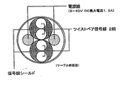
図14は1394シリアルバス・ケーブルの断面図である。1394シリアルバスでは接続ケーブル内に6ピン、即ち2組のツイストペア信号線の他に、電源ラインを設けている。これによって、電源を持たない機器や、故障により電圧低下した機器等にも電力の供給が可能になっている。なお、電源線内を流れる電源の電圧は8〜40V、電流は最大電流DC1.5Aと規定されている。なお、DVケーブルと呼ばれる規格では電源を省いた4ピンで構成されている。
【0022】
《DS−Link符号化》
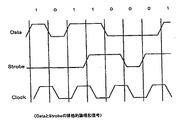
図15は、1394シリアルバスで採用されている、データ転送フォーマットのDS−Link符号化方式を説明するための図である。1394シリアルバスでは、DS−Link(Data/Strobe Link)符号化方式が採用されている。このDS−Link符号化方式は、高速なシリアルデータ通信に適しており、その構成は、2本の信号線を必要とする。より対線のうち1本に主となるデータを送り、他方のより対線にはストローブ信号を送る構成になっている。受信側では、この通信されるデータと、ストローブとの排他的論理和をとることによってクロックを再現する。このDS−Link符号化方式を用いるメリットとして、8/10B変換に比べて転送効率が高いこと、PLL回路が不要となるのでコントローラLSIの回路規模を小さくできること、更には、転送すべきデータが無いときにアイドル状態であることを示す情報を送る必要が無いので、各機器のトランシーバ回路をスリープ状態にすることができることによって、消費電力の低減が図れる、などが挙げられる。
【0023】
《バスリセットのシーケンス》
1394シリアルバスでは、接続されている各機器(ノード)にはノードIDが与えられ、ネットワーク構成として認識されている。このネットワーク構成に変化があったとき、例えばノードの挿抜や電源のON/OFFなどによるノード数の増減などによって変化が生じて、新たなネットワーク構成を認識する必要があるとき、変化を検知した各ノードはバス上にバスリセット信号を送信して、新たなネットワーク構成を認識するモードに入る。このときの変化の検知方法は、1394ポート基板上でのバイアス電圧の変化を検知することによって行われる。
【0024】
あるノードからバスリセット信号が伝達されると、各ノードのフィジカルレイヤはこのバスリセット信号を受けると同時にリンクレイヤにバスリセットの発生を伝達し、かつ他のノードにバスリセット信号を伝達する。最終的にすべてのノードがバスリセット信号を検知した後、バスリセットが起動される。バスリセットは、先に述べたようなケーブル抜挿や、ネットワーク異常等によるハード検出によって起動されるが、プロトコルからのホスト制御などによってフィジカルレイヤに直接命令を出すことによっても起動される。また、バスリセットが起動するとデータ転送は一時中断され、データ転送は当該バスリセットの処理の間待たされることになる。そして、バスリセットの終了後、新しいネットワーク構成のもとで再開される。以上がバスリセットのシーケンスである。
【0025】
《ノードID決定のシーケンス》
バスリセットの後、各ノードは新しいネットワーク構成を構築するために、各ノードにIDを与える動作に入る。このときの、バスリセットからノードID決定までの一般的なシーケンスを図23、24、25のフローチャートを用いて説明する。
【0026】
図23は、バスリセットの発生からノードIDが決定し、データ転送が行えるようになるまでの、一連のバスの作業を示すフローチャートである。まず、ステップS101において、ネットワーク内にバスリセットが発生することを常時監視し、ここでノードの電源ON/OFFなどによってバスリセットが発生するとステップS102に移る。ステップS102では、ネットワークがリセットされた状態から、新たなネットワークの接続状況を知るために、直接接続されている各ノード間において親子関係の宣言がなされる。ステップS103において、すべてのノード間で親子関係が決定されたと判断されると、ステップS104へ進み、一つのルートを決定する。なお、すべてのノード間で親子関係が決定するまでは、ステップS102の親子関係の宣言をおこない、またルートも決定されない。
【0027】
ステップS104でルートが決定されると、ステップS105において、各ノードにIDを与えるノードIDの設定作業が行われる。所定のノード順序で、ノードIDの設定が行われ、すべてのノードにIDが与えられるまで繰り返し設定作業が行われる(ステップS106)。最終的にすべてのノードにIDを設定し終えると、新しいネットワーク構成がすべてのノードにおいて認識されたことになる。よって、処理はステップS106からステップS107へ進み、ノード間のデータ転送が行える状態となり、データ転送が開始される。
【0028】
そして、このステップS107の状態になると、再びバスリセットが発生するのを監視するモードに入り、バスリセットが発生したらステップS101からステップS106までの設定作業が繰り返し行われる。
以上が、図23のフローチャートの説明であるが、図23のフローチャートのバスリセットからルート決定までの部分と、ルート決定後からID設定終了までの手順を図24及び図25を参照して更に詳しく説明する。図24は、各ノードにおけるバスリセットからルート決定までの処理を説明するフローチャートである。また、図25は、ルート決定後からID設定終了までの手順を示すフローチャートである。
【0029】
まず、図24を参照して説明を行う。ステップS201においてバスリセットが発生すると、ネットワーク構成は一旦リセットされ、処理はステップS202へ進む。なお、ステップS201では、バスリセットが発生するのを常に監視している。次に、ステップS202において、リセットされたネットワークの接続状況を再認識する作業の第一段階として、各機器にリーフ(ノード)であることを示すフラグを立てておく。
【0030】
次に、ステップS203において、各機器が自分の持つポートがいくつ他ノードと接続されているのかを調べる。ステップS204では、ポート数に基づいて親子関係の宣言を始めていくために、未定義(親子関係が決定されてない)ポートの数を調べる。バスリセットの直後はポート数=未定義ポート数であるが、親子関係が決定されていくにしたがって、ステップS204で検知する未定義ポートの数は変化していくものである。
【0031】
まず、バスリセットの直後、はじめに親子関係の宣言を行えるのはリーフに限られている。リーフであるというのはステップS203のポート数の確認で知ることができる。即ち、リーフは、親子関係が未定義の段階で未定義ポート数が1のものである。リーフは、ステップS205において、自分に接続されているノードに対して、「自分は子、相手は親」と宣言し動作を終了する。
【0032】
ステップS203でポート数が複数ありブランチと認識したノードは、バスリセットの直後はステップS204で未定義ポート数>1ということになるので、ステップS206へ移り、ブランチというフラグが立てられる。そして、ステップS207でリーフからの親子関係宣言で「親」の受付をするために待つ。リーフである他のノードが親子関係の宣言を行い、ステップS207でそれを受けたブランチは、適宜ステップS204の未定義ポート数の確認を行う。ここで、未定義ポート数が1になっていれば残っているポートに接続されているノードに対して、ステップS205の「Child(自分が子)」の宣言をすることが可能になる。2度目以降のステップS204の処理で未定義ポート数を確認しても2以上あるブランチに対しては、再度ステップS207でリーフ又は他のブランチからの「親」の受付をするために待つ。
【0033】
最終的に、いずれか1つのブランチ、又は例外的にリーフ(子宣言を行えるのにすばやく動作しなかった為)がステップS204の未定義ポート数の確認の結果としてゼロになったら、これにてネットワーク全体の親子関係の宣言が終了したものであり、未定義ポート数がゼロ(すべて親のポートとして決定)になった唯一のノードはステップS208においてルートのフラグが立てられ、ステップS209においてルートとしての認識がなされる。このようにして、図24に示したバスリセットから、ネットワーク内すべてのノード間における親子関係の宣言までが終了する。
【0034】
つぎに、図25のフローチャートについて説明する。
まず、図24までのシーケンスでリーフ、ブランチ、ルートという各ノードのフラグの情報が設定されているので、これを元にして、ステップS301でそれぞれ分類する。各ノードにIDを与える作業として、最初にIDの設定を行うことができるのはリーフからである。リーフ→ブランチ→ルートの順で若い番号(ノード番号=0〜)からIDの設定がなされていく。
【0035】
ステップS302において、ネットワーク内に存在するリーフの数N(Nは自然数)を設定する。この後、ステップS303において各リーフがルートに対してIDを与えるように要求する。この要求が複数ある場合には、ルートはステップS304においてアービトレーションを行い、ステップS305において勝ったノード1つにID番号を与え、負けたノードには失敗の結果通知を行う。ステップS306においてID取得が失敗に終わったリーフは、再度ID要求を出し、同様の作業を繰り返す。
【0036】
IDを取得できたリーフはステップS307においてそのノードのID情報をブロードキャストで全ノードに転送する。1ノードID情報のブロードキャストが終わると、ステップS308において残りのリーフの数Nが1つ減らされる。ここで、ステップS309において、この残りのリーフの数Nが1以上ある場合はステップS303からのID要求の作業を繰り返し行う。そして、最終的にすべてのリーフがID情報をブロードキャストすると、ステップS309においてN=0となり、ブランチのID設定のためにステップS310に移る。
【0037】
ブランチのID設定もリーフの時と同様に行われる。まず、ステップS310においてネットワーク内に存在するブランチの数M(Mは自然数)を設定する。この後、ステップS311として各ブランチがルートに対して、IDを与えるように要求する。これに対してルートは、ステップS312においてアービトレーションを行い、勝ったブランチから順に、リーフに与え終った番号の次に若い番号から与えていく。ステップS313において、ルートは要求を出したブランチにID情報又は失敗結果を通知する。ステップS314において、ID取得が失敗に終わったブランチは、再度ID要求を出し、同様の作業を繰り返す。
【0038】
IDを取得できたブランチからステップS315へ進み、そのノードのID情報をブロードキャストで全ノードに転送する。1ノードID情報のブロードキャストが終わると、ステップS316において、残りのブランチの数Mが1つ減らされる。ここで、ステップS317において、この残りのブランチの数Mが1以上ある場合はステップS311からのID要求の作業を繰り返し、最終的にすべてのブランチがID情報をブロードキャストするまで行われる。すべてのブランチがノードIDを取得すると、ステップS317においてM=0となり、ブランチのID取得モードが終了する。
【0039】
ここまで終了すると、最終的にID情報を取得していないノードはルートのみなので、ステップS318において与えていない番号で最も若い番号を自分のID番号と設定し、ステップS319としてルートのID情報をブロードキャストする。
以上で、図25に示したように、親子関係が決定した後から、すべてのノードのIDが設定されるまでの手順が終了する。
【0040】
次に、一例として、図16に示した実際のネットワークにおけるバスリセット時のネットワーク構築動作を説明する。
図16は、バスリセット時のネットワーク構築動作を説明するための図である。図16において、ノードB(ルート)の下位にはノードAとノードCが直接接続されており、更にノードCの下位にはノードDが直接接続されており、更にノードDの下位にはノードEとノードFが直接接続された階層構造になっている。このような、階層構造やルートノード、ノードIDを決定する手順を以下で説明する。
【0041】
バスリセットがされた後、まず各ノードの接続状況を認識するために、各ノードの直接接続されているポート間において、親子関係の宣言がなされる。この親子とは親側が階層構造で上位となり、子側が下位となると言うことができる。
図16ではバスリセットの後、最初に親子関係の宣言を行なったのはノードAである。基本的にノードの1つのポートにのみ接続があるノード(リーフと呼ぶ)から親子関係の宣言を行なうことができる。これは、自分には1ポートの接続のみしかない、ということをまず知ることができるので、これによってネットワークの端であることを認識し、その中で早く動作を行なったノードから親子関係が決定されていく。こうして親子関係の宣言を行なった側(A-B間ではノードA)のポートが子と設定され、相手側(ノードB)のポートが親と設定される。こうして、ノードA−B間では子−親、ノードE−D間で子−親、ノードF−D間で子−親と決定される。
【0042】
さらに1階層あがって、今度は複数個接続ポートを持つノード(ブランチと呼ぶ)のうち、他ノードからの親子関係の宣言を受けたものから順次、更に上位に親子関係の宣言を行なっていく。図16ではまずノードDがD−E間、D−F間と親子関係が決定した後、ノードCに対する親子関係の宣言を行っており、その結果ノードD−C間で子−親と決定している。
【0043】
ノードDからの親子関係の宣言を受けたノードCは、もう一つのポートに接続されているノードBに対して親子関係の宣言を行なっている。これによってノードC−B間で子−親と決定している。
このようにして、図16のような階層構造が構成され、最終的に、接続されているすべてのポートにおいて親となったノードBが、ルートノードと決定されることになる。ルートは1つのネットワーク構成中に一つしか存在しないものである。
【0044】
なお、この図16においてノードBがルートノードと決定されたが、これはノードAから親子関係宣言を受けたノードBが、他のノードに対して親子関係宣言を早いタイミングで行なっていれば、ルートノードは他ノードに移っていたこともあり得る。すなわち、伝達されるタイミングによってはどのノードもルートノードとなる可能性があり、同じネットワーク構成でもルートノードは一定とは限らない。
【0045】
ルートノードが決定すると、次は各ノードIDを決定するモードに入る。ここではすべてのノードが、決定した自分のノードIDを他のすべてのノードに通知する(ブロードキャスト機能)。自己ID情報は、自分のノード番号、接続されている位置の情報、持っているポートの数、接続のあるポートの数、各ポートの親子関係の情報等を含んでいる。
【0046】
ノードID番号の割り振りの手順としては、まず1つのポートにのみ接続があるノード(リーフ)から起動することができ、この中から順にノード番号=0、1、2…と割り当てられる。ノードIDを獲得したノードは、ノード番号を含む情報をブロードキャストで各ノードに送信する。これによって、そのID番号は『割り当て済み』であることが認識される。
【0047】
すべてのリーフが自己ノードIDを取得し終ると、次はブランチへ移りリーフに引き続いたノードID番号が各ノードに割り当てられる。リーフと同様に、ノードID番号が割り当てられたブランチから順次ノードID情報をブロードキャストし、最後にルートノードが自己ID情報をブロードキャストする。すなわち常にルートは最大のノードID番号を所有するものである。
【0048】
以上のようにして、階層構造全体のノードIDの割り当てが終わり、ネットワーク構成が再構築され、バスの初期化作業が完了する。
《アービトレーション》
1394シリアルバスでは、データ転送に先立って必ずバス使用権のアービトレーション(調停)を行なう。1394シリアルバスは個別に接続された各機器が、転送された信号をそれぞれ中継することによって、ネットワーク内すべての機器に同信号を伝えるように、論理的なバス型ネットワークであるので、パケットの衝突を防ぐ意味でアービトレーションは必要である。これによってある時間には、たった一つのノードのみ転送を行なうことができる。
【0049】
図17は1394紙リアルバスにおけるアービトレーションを説明する図である。特に、図17の(a)はバス使用要求の流れを示し、図17の(b)はバス使用許可の流れを示す。
アービトレーションが始まると、1つもしくは複数のノードが親ノードに向かって、それぞれバス使用権の要求を発する。図17(a)のノードCとノードFがバス使用権の要求を発しているノードである。これを受けた親ノード(図17ではノードA)は更に親ノードに向かって、バス使用権の要求を発する(中継する)。この要求は最終的に調停を行なうルートに届けられる。
【0050】
バス使用要求を受けたルートノード(ノードB)は、どのノードにバスを使用させるかを決める。この調停作業はルートノードのみが行なえるものであり、調停によって勝ったノードにはバスの使用許可が与えられる。図17の(b)ではノードCに使用許可が与えられ、ノードFの使用要求は拒否されたことを示している。アービトレーションに負けたノードに対してはDP(data prefix)パケットを送り、要求が拒否されたことを知らせる。要求が拒否されたノードのバス使用要求は次回のアービトレーションまで待たされる。
【0051】
以上のようにして、アービトレーションに勝ってバスの使用許可を得たノードは、以降データの転送を開始できる。ここで、アービトレーションの一連の流れをフローチャート図26を参照して説明する。図26はアービトレーションの処理手順を表すフローチャートである。
ノードがデータ転送を開始できる為には、バスがアイドル状態であることが必要である。先に行われていたデータ転送が終了して、現在バスが空き状態であることを認識するためには、各転送モードで個別に設定されている所定のアイドル時間ギャップ長(例.サブアクション・ギャップ)を経過する事によって、各ノードは自分の転送が開始できると判断する。
【0052】
ステップS401において、Asyncデータ、Isoデータ等それぞれ転送するデータに応じた所定のギャップ長が得られたか判断する。所定のギャップ長が得られない限り、転送を開始するために必要なバス使用権の要求はできないので、所定のギャップ長が得られるまで待つ。ステップS401で所定のギャップ長が得られたら、ステップS402において転送すべきデータがあるかを判断し、あればステップS403へ進む。
【0053】
ステップS403では、データ転送をするためにバスを確保するよう、バス使用権の要求をルートに対して発する。このときの、バス使用権の要求を表す信号の伝達は、図17の(a)に示したように、ネットワーク内の各機器を中継しながら、最終的にルートに届けられる。一方、ステップS402で転送するデータがない場合は、そのまま待機する。
次に、ステップS404において、ルートノードはステップS403で発行されたバス使用要求を受信する。そして、ステップS405において、ルートは使用要求を出したノードの数を調べる。ステップS405で使用要求を出したノードの数が1(使用権要求を出したノードが1つ)だったら、そのノードに直後のバス使用許可が与えられることとなる。一方、ステップS405において、ノード数>1(使用要求を出したノードは複数)だったら、ルートはステップS406において使用許可を与えるノードを1つに決定する調停作業を行う。この調停作業は公平なものであり、毎回同じノードばかりが許可を得る様なことはなく、平等に権利を与えていくような構成となっている(フェア・アービトレーション)。
【0054】
次に、ステップS407において、ステップS406で使用要求を出した複数ノードの中からルートが調停して使用許可を得た1つのノードと、敗れたその他のノードに分ける選択を行う。ここで、調停されて使用許可を得た1つのノード、またはステップS405において使用要求ノード数=1で調停無しに使用許可を得たノードには、ステップS408として、ルートはそのノードに対して許可信号を送る。許可信号を得たノードは、受け取った直後に転送すべきデータ(パケット)を転送開始する。また、ステップS406の調停で敗れて、バス使用が許可されなかったノードには、ステップS409において、ルートから、アービトレーション失敗を示すDP(data prefix)パケットを送られ、これを受け取ったノードは再度転送を行うためのバス使用要求を出すため、ステップS401まで戻り、所定ギャップ長が得られるまで待機する。
【0055】
以上が1394シリアルバスによるアービトレーションの流れである。
《アシンクロナス(Asynchronous、非同期)転送》
アシンクロナス転送は、非同期転送である。図18はアシンクロナス転送における時間的な遷移状態を示す図である。図18の最初のサブアクション・ギャップは、バスのアイドル状態を示すものである。このアイドル時間が一定値になった時点で、転送を希望するノードはバスが使用できると判断してバス使用要求を発行し、バス獲得のためのアービトレーションが実行される。
【0056】
アービトレーションでバスの使用許可を得ると、次にデータの転送がパケット形式で実行される。データ転送後、当該データを受信したノードは、転送されたデータに対しての受信結果のack(受信確認用返送コード)をack gapという短いギャップの後、返送して応答するか、応答パケットを送ることによって転送が完了する。ackは4ビットの情報と4ビットのチェックサムからなり、成功か、ビジー状態か、ペンディング状態であるかといった情報を含み、すぐに送信元ノードに返送される。
【0057】
次に、アシンクロナス転送のパケットフォーマットを説明する。図19はアシンクロナス転送のパケットフォーマットの例を示す図である。
パケットには、データ部及び誤り訂正用のデータCRCの他にヘッダ部がある。ヘッダ部には図19に示したような、目的ノードID、ソースノードID、転送データ長さや各種コードなどが書き込まれ、転送が行なわれる。また、アシンクロナス転送は自己ノードから相手ノードへの1対1の通信である。転送元ノードから転送されたパケットは、ネットワーク中の各ノードに行き渡るが、自分宛てのアドレス以外のものは無視されるので、宛先の1つのノードのみが読込むことになる。以上がアシンクロナス転送の説明である。
【0058】
《アイソクロナス(Isochronous、同期)転送》
アイソクロナス転送は同期転送である。1394シリアルバスの最大の特徴であるともいえるこのアイソクロナス転送は、特に映像データや音声データといったマルチメディアデータなど、リアルタイムな転送を必要とするデータの転送に適した転送モードである。また、アシンクロナス転送(非同期)が1対1の転送であったのに対し、このアイソクロナス転送はブロードキャスト機能によって、転送元の1つのノードから他のすべてのノードへ一様にデータが転送される。
【0059】
図20はアイソクロナス転送における、時間的な遷移状態を示す図である。アイソクロナス転送は、バス上一定時間毎に実行される。この時間間隔をアイソクロナスサイクルと呼ぶ。アイソクロナスサイクル時間は、125μsである。この各サイクルの開始時間を示し、各ノードの時間調整を行なう役割を担っているのがサイクル・スタート・パケットである。サイクル・スタート・パケットを送信するのは、サイクル・マスタと呼ばれるノードであり、1つ前のサイクル内のデータ転送終了後、所定のアイドル期間(サブアクションギャップ)を経た後、本サイクルの開始を告げるサイクル・スタート・パケットを送信する。このサイクル・スタート・パケットの送信される時間間隔が125μsとなる。
【0060】
また、図20にチャネルA、チャネルB、チャネルCと示したように、1サイクル内において複数種のパケットがチャネルIDをそれぞれ与えられることによって、区別して転送できる。これによって同時に複数ノード間でのリアルタイムな転送が可能であり、また受信するノードでは自分が欲しいチャネルIDのデータのみを取り込む。このチャネルIDは送信先のアドレスを表すものではなく、データに対する論理的な番号を与えているに過ぎない。よって、あるパケットの送信は1つの送信元ノードから他のすべてのノードに行き渡る、ブロードキャストで転送されることになる。
【0061】
アイソクロナス転送のパケット送信に先立って、アシンクロナス転送同様アービトレーションが行われる。しかし、アシンクロナス転送のように1対1の通信ではないので、アイソクロナス転送にはack(受信確認用返信コード)は存在しない。
また、図20に示した iso gap(アイソクロナスギャップ)とは、アイソクロナス転送を行なう前にバスが空き状態であると認識するために必要なアイドル期間を表している。この所定のアイドル期間を経過すると、アイソクロナス転送を行ないたいノードはバスが空いていると判断し、転送前のアービトレーションを行なうことができる。
【0062】
つぎに、アイソクロナス転送のパケットフォーマットについて説明する。図21はアイソクロナス転送のパケットフォーマットの例を示す図である。
各チャネルに分かれた、各種のパケットにはそれぞれデータ部及び誤り訂正用のデータCRCの他に、ヘッダ部がある。そのヘッダ部には図21に示したような、転送データ長やチャネルNO.、その他各種コード及び誤り訂正用のヘッダCRCなどが書き込まれ、転送が行なわれる。以上がアイソクロナス転送の説明である。
【0063】
《バス・サイクル》
実際の1394シリアルバス上の転送では、アイソクロナス転送と、アシンクロナス転送は混在できる。図22は、アイソクロナス転送とアシンクロナス転送とが混在した、バス上の転送状態の時間的な遷移の様子を表した図である。
アイソクロナス転送はアシンクロナス転送より優先して実行される。その理由は、サイクル・スタート・パケットの後、アシンクロナス転送を起動するために必要なアイドル期間のギャップ長(サブアクションギャップ)よりも短いギャップ長(アイソクロナスギャップ)で、アイソクロナス転送を起動できるからである。したがって、アシンクロナス転送より、アイソクロナス転送は優先して実行されることとなる。
【0064】
図22に示した一般的なバスサイクルにおいて、サイクル#mのスタート時にサイクル・スタート・パケットがサイクル・マスタから各ノードに転送される。これによって、各ノードで時刻調整を行ない、所定のアイドル期間(アイソクロナスギャップ)を待ってからアイソクロナス転送を行なうべきノードはアービトレーションを行い、パケット転送に入る。図22ではチャネルeとチャネルsとチャネルkが順にアイソクロナス転送されている。
【0065】
このアービトレーションからパケット転送までの動作を、与えられているチャネル分繰り返し行なった後、サイクル#mにおけるアイソクロナス転送がすべて終了したら、アシンクロナス転送を行うことができるようになる。
アイドル時間がアシンクロナス転送が可能なサブアクションギャップに達することによって、アシンクロナス転送を行いたいノードはアービトレーションの実行に移れると判断する。ただし、アシンクロナス転送が行える期間は、アイソクロナス転送終了後から、次のサイクル・スタート・パケットを転送すべき時間(cycle synch)までの間に、アシンクロナス転送を起動するためのサブアクションギャップが得られた場合に限っている。
【0066】
図22のサイクル#mでは3つのチャネル分のアイソクロナス転送と、その後アシンクロナス転送(ackを含む)が2パケット(パケット1、パケット2)転送されている。このアシンクロナスパケット2の後は、サイクルm+1をスタートすべき時間(cycle synch)にいたるので、サイクル#mでの転送はここまでで終わる。
【0067】
ただし、非同期または同期転送動作中に次のサイクル・スタート・パケットを送信すべき時間(cycle synch)に至ったとしたら、無理に中断せず、その転送が終了した後のアイドル期間を待ってから次サイクルのサイクル・スタート・パケットを送信する。すなわち、1つのサイクルが125μs以上続いたときは、その分次サイクルは基準の125μsより短縮されたとする。このようにアイソクロナス・サイクルは125μsを基準に超過、短縮し得るものである。しかし、アイソクロナス転送はリアルタイム転送を維持するために毎サイクル必要であれば必ず実行され、アシンクロナス転送はサイクル時間が短縮されたことによって次以降のサイクルにまわされることもある。こういった遅延情報も含めて、サイクル・マスタによって管理される。
【0068】
<実施形態1>
本発明の実施形態1では、画像処理装置と出力装置とが接続され、その画像処理装置で処理された画像データに基づく画像を出力装置で出力する画像処理システムにおいて、画像処理装置としてデジタルカメラ、出力装置としてプリンタで構成した図4に示すような画像処理システムを例に挙げて説明する。
【0069】
まず、デジタルカメラの機能構成及びその動作について、図2を用いて説明する。
図2は本発明の実施形態1のデジタルカメラの機能構成を示すブロック図である。
尚、ここでは、図1に示した画像データに対応する画像を記録する場合を例に挙げて説明する。
【0070】
まず、レンズ系21より得られる画像はCCD素子22面上に結像される。CCD素子22より得られたアナログ信号は、A/D変換部23によりデジタル信号へと変換される。変換されたデジタル信号は、画像処理部24へと送信され、色変換処理、エッジ強調処理、ガンマ補正処理等の画像処理が施された画像データに変換される。次に、画像データは画像変換部25へと送信される。画像変換部25では、プリンタの記録ヘッドの1走査によって記録可能な画素数幅毎に画像データが分割され、分割された画像データ毎にJPEG圧縮されてデータ記録部26に記録される。
【0071】
尚、画像データのデータ記録部26への記録の管理は、データ記録部26のアドレスに基づいて行われる。例えば、プリンタの記録に用いる1枚の記録媒体分の画像データAが3つの画像データA1、A2、A3に分割されてJPEG圧縮されている場合、画像データA1、A2、A3が記録されているデータ記録部26のそれぞれの先頭アドレスが、データ記録部26内のアドレス管理部(不図示)によって管理される。
【0072】
以上のような処理を画像データB、画像データCに対しても実行する。この場合、画像データBは、画像データB1、B2、B3に分割されJPEG圧縮されてデータ記録部26へ記録され、画像データCは画像データC1、C2、C3に分割されJPEG圧縮されてデータ記録部26へ記録される。
次に、上記のデジタルカメラに接続されたプリンタの機能構成及び動作について、図3を用いて説明する。
【0073】
尚、実施形態1のプリンタは、インクジェット方式による記録ヘッドを搭載したインクジェットプリンタであるとし、記録ヘッドは、その走査方向(ピクセル方向)及び記録ヘッドの走査方向とは垂直な方向、つまり、記録媒体の搬送方向(ライン方向)にそれぞれ64個のノズルが配置されているとする。また、各ノズルは画像データの1画素に対応し、記録媒体はA4サイズのカットシートを用いるとする。
【0074】
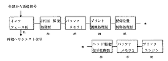
図3は本発明の実施形態1のプリンタの機能構成を示すブロック図である。
ユーザは、まず、プリンタ上にあるインタフェース部31により、デジタルカメラ内のデータ記録部26に記録された画像データをいくつ記録するか、どの画像データを記録するか等のプリンタで記録する画像データの選択を行う。尚、プリンタで記録する画像データの選択は、詳述しないが、デジタルカメラにディスプレイがあれば、そのディスプレイ上にデータ記録部26に記録されている画像データを表示して選択しても良いし、データ記録部26に記録される画像データのインデックスプリントを使用して選択しても良い。
【0075】
ここでは、データ記録部26に記録されている画像データAをA4サイズの記録媒体に1枚記録する場合を例に挙げて説明する。
プリンタで記録する画像データ(画像データA)を選択すると、プリンタはインタフェース部31からデジタルカメラへ画像データを得るためのリクエスト信号を送信する。リクエスト信号は、デジタルカメラのインタフェース部27に送信される。そして、デジタルカメラはそのリクエスト信号に答えるべく、画像データAを分割しJPEG圧縮した画像データの1つをプリンタへ送信する。
【0076】
尚、上述したように、画像データAを分割する分割単位は、プリンタの記録ヘッドの1走査で記録可能な画素数幅で決定される。例えば、画像データAが832画素(ライン)×640画素(ピクセル)である場合は、記録ヘッドのピクセル方向のノズルの数(画素数)が64であるので、画像データAは832画素(ライン)×64画素(ピクセル)単位で分割される。即ち、画像データAは、画像データA1、 A2、A3、…、A9、A10の10個に分割された後、それぞれがJPEG圧縮されデータ記録部26に記録されている。
【0077】
また、記録ヘッドの1走査で記録可能な画素数は、ユーザが予めデジタルカメラのインタフェース部27より設定するか、あるいはデジタルカメラのデータ記録部26に記録されている画像データをプリンタへ送信する前に、プリンタがデジタルカメラに対して通知するような構成にしても良い。また、あるいは、後述する実施形態3のように、予めデフォルト値として設定していても良い。
【0078】
次に、プリンタがデジタルカメラより受信したJPEG圧縮された画像データ(例えば、画像データA1)は、JPEG解凍処理部32へと送信される。そして、JPEG解凍処理部32でJPEG圧縮された画像データA1がJPEG解凍される。JPEG解凍された画像データA1は、プリント画像処理部33によって、色変換処理、2値化処理がなされる。2値化された画像データA1は、記録位置制御処理部34へと送信され、記録媒体上の記録すべき位置が管理される。
【0079】
尚、記録位置制御処理部34における位置制御は、2値化された画像データに対応するバッファメモリ36の書き込み位置を制御することによって行われる。次に、位置制御された2値化された画像データは、ヘッド駆動信号変換部35へと送信され、記録ヘッドを動作させるための記録信号へと変換される。次に、記録信号はバッファメモリ36に一旦格納される。そして、記録位置制御処理部34による位置制御に基づいて、記録信号は順次プリンタエンジン37に送信され、その記録信号に基づく画像が記録媒体上に記録される。
【0080】
以上が実施形態1のプリンタの記録ヘッドの1走査による記録手順である。
記録ヘッドの1走査による記録が完了すると、再び、プリンタのインタフェース部31により、次の記録ヘッドの1走査の記録に必要な画像データをデジタルカメラから得るために、デジタルカメラへリクエスト信号が送信される。デジタルカメラでは、プリンタよりリクエスト信号を受信すると、プリンタの次の記録ヘッドの1走査に必要なJPEG圧縮された画像データ(ここでは、画像データA2)をプリンタへ送信する。そして、上述した同様の記録手順によって、デジタルカメラより受信したJPEG圧縮された画像データA2に対応する画像が、記録媒体上に記録される。
【0081】
以上のような記録手順を、分割された圧縮された画像データに対し順次行い、画像データA10に対応する画像が記録媒体上に記録されると、画像データAに対応する画像の記録が完了する。
次に、記録ヘッドの走査方向に複数の画像を記録する場合の記録手順について説明する。尚、説明を簡単にするために、プリンタが選択する記録する画像データは、上述した画像データAと、画像データAと同サイズの画像データBが選択され、また、図6に示すように記録ヘッドの走査方向に、画像データAに対応する画像A、画像データBに対応する画像Bを記録するように設定されているものとする。
【0082】
まず、デジタルカメラより入力された画像Aに対応する画像データA、画像Bに対応する画像データBは、上述した同様の記録手順で、記録ヘッドの1走査で記録可能な画素数幅毎に分割されJPEG圧縮されて、データ記録部26に記録される。
続いて、プリンタより記録に必要な画像データのリクエスト信号がデジタルカメラへ送信される。プリンタよりリクエスト信号を受信したデジタルカメラは、プリンタの最初の記録ヘッドの1走査に必要な画像データとして、JPEG圧縮された画像データA1、続いて、JPEG圧縮された画像データB1をプリンタへ送信する。
【0083】
そして、プリンタは、JPEG圧縮された画像データA1をデジタルカメラより受信し、上述の記録手順を経てバッファメモリ36の所定の位置に一旦格納する。続いて、JPEG圧縮された画像データB1を受デジタルカメラより受信し、同様の記録手順によって、バッファメモリ36の画像データA1が格納されている位置とは異なる位置に一旦格納する。バッファメモリ36に画像データA1と画像データB1が格納されると、記録位置制御処理部34の位置制御に基づいて、順次プリンタエンジン37に送信され対応する画像が記録媒体上に記録される。
【0084】
以上のような記録手順を、画像データA2、画像データB2、画像データA3、画像データB3、…、画像データA10、画像データB10に対し順次行い、画像データA10、画像データB10に対応する画像が記録媒体上に記録されると、画像データAに対応する画像A、画像データBに対応する画像Bの記録が完了する。
【0085】
尚、実施形態1では、デジタルカメラのデータ記録部26に記録されている画像データをプリンタに接続して対応する画像を出力する構成について説明したが、図5に示すようにパーソナルコンピュータに接続して対応する画像をパーソナルコンピュータのモニタに出力することができることは言うまでもない。
また、複数の画像を記録する例として、2つの画像A、画像Bを記録ヘッドの走査方向へ並べて記録する場合について説明したが、2つ以上の画像を記録ヘッドの走査方向に並べて記録することも可能である。更には、図7に示すような記録ヘッドの走査方向及び記録媒体の搬送方向に複数の画像を並べて記録することも可能である。
【0086】
更に、デジタルカメラに入力された画像に対応する画像データの圧縮方式として、JPEG圧縮方式を用いてるが、これに限定されるものではない。
以上説明したように、実施形態1によれば、デジタルカメラより入力した画像データを、プリンタの記録ヘッドの1走査で記録可能な画素数毎に分割し、その分割された画像データを記録ヘッドの1走査毎に受信して記録するため、デジタルカメラからプリンタへの画像データの送信動作と、プリンタの記録動作を効率的に実行するこができる。その結果、画像処理システムのトータルスループットを向上することができる。
【0087】
また、プリンタの記録ヘッドの1走査に必要な画像データを順次受信し記録を行っていくので、記録媒体に記録する画像全体の画像データを記憶するための記憶容量を持つバッファメモリ36を必要としない。その結果、バッファメモリ36の記憶容量を低減することができる。
<実施形態2>
実施形態2では、デジタルカメラとプリンタとが接続され、デジタルカメラで入力された画像データに対応する画像のサイズを拡大あるいは縮小してプリンタで記録する画像処理システムを実施形態2として説明する。
【0088】
尚、実施形態2のデジタルカメラの機能構成及び動作については、実施形態1の図1と同様であるので、ここではその詳細を省略する。
次に、実施形態2のプリンタの機能構成及び動作について、図8を用いて説明する。
図8は本発明の実施形態2のプリンタの機能構成を示すブロック図である。
【0089】
尚、実施形態2のプリンタの記録ヘッドは、実施形態1のプリンタの記録ヘッドと同様のものを用いるとする。
ユーザは、まず、プリンタ上にあるインタフェース部31により、デジタルカメラ内のデータ記録部26に記録された画像データをいくつ記録するか、どの画像データを記録するか等のプリンタで記録する画像データの選択を行うとともに、記録する画像のサイズ、拡大あるいは縮小の倍率を設定する。尚、プリンタで記録する画像データの選択及びサイズの設定は、詳述しないが、デジタルカメラにディスプレイがあれば、そのディスプレイ上にデータ記録部26に記録される画像データを表示して選択しても良いし、データ記録部26に記録される画像データのインデックスプリントを使用して選択しても良い。
【0090】
ここでは、上述した実施形態1の画像データAを2倍に拡大してA4サイズの記録媒体に1枚記録する場合を例に挙げて説明する。
プリンタで記録する画像データ(画像データA)を選択及びその記録するサイズを設定すると、プリンタはインタフェース部81からデジタルカメラへ画像データを得るためのリクエスト信号を送信する。リクエスト信号は、デジタルカメラのインタフェース部27に送信される。そして、デジタルカメラはそのリクエスト信号に答えるべく、画像データAを分割してJPEG圧縮した画像データA1をプリンタへ送信する。
【0091】
プリンタがデジタルカメラより受信したJPEG圧縮された画像データA1は、JPEG解凍処理部82へと送信される。そして、JPEG解凍処理部82でJPEG圧縮された画像データA1がJPEG解凍される。JPEG解凍された画像データA1は、バッファメモリ1(83)に格納される。バッファメモリ1(83)に格納された画像データは、プリント画像処理部84で、画像サイズの変換が行われる。ここでは、画像データを2倍に拡大するように設定されているので、バッファメモリ1(83)から画像データA1(832画素×64画素)の内、832画素×32画素分の画像データを読み出し、周知の倍率変換処理によって1664画素×64画素の画像データに拡大する。
【0092】
そして、その拡大された画像データに対し、色変換処理、2値化処理がなされる。2値化された画像データは、記録位置制御処理部85へと送信され、記録媒体上の記録すべき位置が管理される。尚、記録位置制御処理部85における位置制御は、2値化された画像データに対応するバッファメモリ2(87)の書き込み位置を制御することによって行われる。そして、位置制御された2値化された画像データは、ヘッド駆動信号変換部86へと送信され、記録ヘッドを動作させるための記録信号へと変換される。次に、記録信号はバッファメモリ2(87)に一旦格納される。そして、記録位置制御処理部85による位置制御に基づいて、記録信号は順次プリンタエンジン88に送信され、その記録信号に基づく画像が記録される。
【0093】
次に、バッファメモリ1(83)に格納されている画像データA1の残りの832画素×32画素分の画像データを、同様の手順によって、記録媒体上の記録すべき位置に記録する。
バッファメモリ1(83)に格納されている画像データがすべて記録されたら、プリンタは次の画像データA2のリクエスト信号をデジタルカメラへと送信する。そして、デジタルカメラから次の画像データA2を受信したら、画像データA1に対して行った同様の手順によって、記録媒体上の記録すべき位置に画像データA2に対応する画像を記録する。
以上のような記録手順を、分割された圧縮された画像データに対し順次行い、画像データA10に対応する画像が記録媒体上に記録されると、画像データAに対応する画像の記録が完了する。
次に画像データAを1/2倍に縮小してA4サイズの記録媒体に1枚記録する場合について説明する。
【0094】
プリンタで記録する画像データ(画像データA)を選択及びその記録するサイズを設定すると、プリンタはインタフェース部81からデジタルカメラへ画像データを得るためのリクエスト信号を送信する。リクエスト信号は、デジタルカメラのインタフェース部27に送信される。そして、デジタルカメラはそのリクエスト信号に答えるべく、画像データAを分割してJPEG圧縮した画像データA1をプリンタへ送信する。
プリンタがデジタルカメラより受信したJPEG圧縮された画像データA1は、JPEG解凍処理部82へと送信される。そして、JPEG解凍処理部82でJPEG圧縮された画像データA1がJPEG解凍される。JPEG解凍された画像データA1は、バッファメモリ83に格納される。バッファメモリ1(83)に格納された画像データは、プリント画像処理部84で、画像サイズの変換が行われる。ここでは、画像データを1/2倍に縮小するように設定されているので、バッファメモリ1(83)から画像データA1(832画素×64画素)を読み出し、周知の倍率変換処理によって416画素×32画素の画像データに縮小する。
そして、その縮小された画像データに対し、色変換処理、2値化処理がなされる。2値化された画像データは、記録位置制御処理部85へと送信され、記録媒体上の記録すべき位置が管理される。位置制御された2値化された画像データは、ヘッド駆動信号変換部86へと送信され、記録ヘッドを動作させるための記録信号へと変換される。次に、記録信号はバッファメモリ2(87)に一旦格納される。
【0095】
次に、同様の手順によって、デジタルカメラより画像データA2を受信し、バッファメモリ2(87)の画像データA1に対応する記録信号が格納されている位置の後に画像データA2に対応する記録信号を格納する。画像データA1、A2それぞれに対応するの2つの記録信号がバッファメモリ2(87)に格納されると、それぞれの記録信号は、記録位置制御処理部85による位置制御に基づいて、順次プリンタエンジン88に送信され、その記録信号に基づく画像が記録媒体上に記録される。
【0096】
以上が、画像データを1/2倍に縮小して記録する場合の記録ヘッドの1走査による記録手順である。
記録ヘッドの1走査による記録が終了すると、再び、プリンタのインタフェース部81により、次の記録ヘッドの1走査の記録に必要な画像データをデジタルカメラから得るために、デジタルカメラへリクエスト信号が送信される。デジタルカメラでは、プリンタよりリクエスト信号を受信すると、プリンタの次の記録ヘッドの走査に必要なJPEG圧縮された画像データ(ここでは、画像データA3、A4)をプリンタへ送信する。そして、上述した同様の記録手順によって、デジタルカメラより受信したJPEG圧縮された画像データA3、A4に対応する画像が、記録媒体上の記録すべき位置に記録される。
以上のような記録手順を、分割された圧縮された画像データに対し順次行い、画像データA10に対応する画像が記録媒体上に記録されると、画像データAに対応する画像の記録が完了する。
尚、実施形態2では、記録する画像データのサイズとして2倍に拡大して記録する場合と、1/2倍に縮小して記録する場合を例に挙げて説明したが、3倍、4倍に拡大して記録、1/3倍、1/4倍に縮小して記録する場合においても、同様の手順で対応できる。また、ここでは、記録媒体に1つの画像を記録する場合について説明したが、実施形態1で説明したように、複数の画像を記録媒体上に記録することも可能である。
以上説明したように、実施形態2によれば、デジタルカメラで入力された画像データのサイズを変更し、その変更された画像データに対応する画像をプリンタで記録する場合にも、実施形態1と同様の効果を得ることができる。
【0097】
<実施形態3>
実施形態1、実施形態2では、デジタルカメラより入力された画像データを分割する単位である画素数幅を、ユーザあるいはプリンタより入力する構成であったが、これを予め決定されたデフォルト値を用いても良い。以下、分割する単位である画素数幅がデフォルトで決定されているデジタルカメラとプリンタが接続され、デジタルカメラで入力された画像データに対応する画像をプリンタで記録する画像処理システムを実施形態3として説明する。
【0098】
尚、実施形態3のデジタルカメラ及びプリンタの機能構成及び動作については、実施形態2と同様であるので、ここではその詳細を省略する。
また、一般的に、プリンタの記録ヘッドのノズル数はデータ制御の問題上、8の倍数となる。すなわち。記録ヘッドの1走査で記録可能となる画素数幅は8の倍数となる。そのため、デジタルカメラ内で予め決定されている画像データを分割する単位である画素数幅は8の倍数に設定される。また、画像データに対するJPEG圧縮の圧縮単位が8画素×8画素であることからも、画素数幅を8の倍数に設定することが好ましい。
【0099】
ここでは、デジタルカメラ内で予め決定されている画像データを分割する単位である画素数幅が32であり、上述した実施形態1の画像データAをA4サイズの記録媒体に1枚記録する場合を例に挙げて説明する。
まず、デジタルカメラにおいて、データ記録部26に記録されている画像データAのサイズが832画素×640画素であるので、画像データAは832画素×32画素毎の画像データA1、A2、…A20の20個に分割されてJPEG圧縮されデータ記録部26に記録される。
そして、プリンタのインタフェース部31より画像データを得るためのリクエスト信号がデジタルカメラへ送信されると、デジタルカメラは画像データの分割単位である画素数幅(ここでは、32)をプリンタへ送信する。プリンタはその画素数幅と記録ヘッドの1走査で記録可能な画素数幅を比較し、その比較結果に基づいて、1度にデジタルカメラより受信することができる分割されJPEG圧縮された画像データの数を決定する。(実施形態3では、記録ヘッドの1走査で記録可能な画素数幅が64であるため、2つの分割され圧縮された画像データが必要となる。)
そこで、プリンタはJPEG圧縮された画像データA1をデジタルカメラより受信し、その受信したJPEG圧縮された画像データA1は、JPEG解凍処理部82へと送信される。そして、JPEG解凍処理部32でJPEG圧縮された画像データA1がJPEG解凍される。JPEG解凍された画像データA1は、バッファメモリ1(83)に格納される。続いて、JPEG圧縮された画像データA2をデジタルカメラより受信し、同様の手順で、バッファメモリ1(83)へ格納する。そのバッファメモリ1(83)に格納された画像データに対し、色変換処理、2値化処理がなされる。2値化された画像データは、記録位置制御処理部85へと送信され、記録媒体上の記録すべき位置が管理される。
【0100】
次に、位置制御された2値化された画像データは、ヘッド駆動信号変換部86へと送信され、記録ヘッドを動作させるための記録信号へと変換される。次に、記録信号はバッファメモリ2(87)に一旦格納される。そして、記録位置制御処理部85による位置制御に基づいて、記録信号は順次プリンタエンジン88に送信され、その記録信号に基づく画像が記録媒体上に記録される。
【0101】
以上が、デジタルカメラ内の画像データを分割する単位である画素数幅が予め決定されている場合の記録ヘッドの1走査による記録手順である。
記録ヘッドの1走査による記録が終了すると、再び、プリンタのインタフェース部81により、次の記録ヘッドの1走査の記録に必要な画像データをデジタルカメラから得るために、デジタルカメラへリクエスト信号が送信される。デジタルカメラでは、プリンタよりリクエスト信号を受信すると、プリンタの次の記録ヘッドの走査に必要なJPEG圧縮された画像データ(ここでは、画像データA3、A4)をプリンタへ送信する。そして、上述した同様の記録手順によって、デジタルカメラより受信したJPEG圧縮された画像データA3、A4に対応する画像が、記録媒体上の記録すべき位置に記録される。
【0102】
以上のような記録手順を、分割された圧縮された画像データに対し順次行い、画像データA20に対応する画像が記録媒体上に記録されると、画像データAに対応する画像の記録が完了する。
尚、実施形態3では、デジタルカメラ内の画像データを分割する単位である画素数幅は32で予め決定されていたが 、8の倍数であればこれに限られるものではない。
【0103】
以上説明したように、実施形態3によれば、デジタルカメラ内の画像データを分割する単位である画素数幅が予め決定されている場合でも、その画素数幅とプリンタの記録ヘッドの1走査で記録可能な画素数幅とを比較することで、記録ヘッドの1走査に必要な画像データを受信できる。そのため、このような場合にも、実施形態1と同様の効果を得ることができる。
【0104】
尚、本発明の画像処理システムのデジタルカメラ内で画像データを分割する分割単位である画素数幅の決定方法は、ユーザからの入力あるいはプリンタの記録ヘッドの1走査で記録可能な画素数幅から獲得する方法と、デジタルカメラ内で予め決定しておく方法の2つに大別される。この観点に着目すると、実施形態1、2は、分割単位である画素数幅をユーザからの入力あるいはプリンタより獲得する方法、実施形態3がデジタルカメラ内で予め画素数幅を決定しておく方法に該当する。
【0105】
そこで、本発明の画像処理システムで実行される処理の概要として、実施形態1、2における画像処理システムで実行される処理と、実施形態3における画像処理システムで実行される処理について、図9、図10のフローチャートを用いて説明する。
まず、実施形態1、2における画像処理システムで実行される処理の概要について、図9を用いて説明する。
【0106】
図9は本発明の実施形態1、2の画像処理システムの処理の概要を示すフローチャートである。
まず、デジタルカメラ側において、ステップS101で、記録ヘッドの1走査で記録可能な画素数をユーザからの入力あるいはプリンタより獲得する。次に、ステップS202で、獲得した画素数に応じて画像データを分割する。次に、分割された画像データをJPEG圧縮しデータ記録部26に記録する。
【0107】
プリンタ側において、ステップS104で、出力させる画像データの選択、画像サイズの設定をインタフェース部31(あるいはインタフェース部81)によて入力する。ステップS105で、インタフェース部31(あるいはインタフェース部81)からの入力に応じて、デジタルカメラよりJPEG圧縮された画像データを入力する。ステップS106で、入力されたJPEG圧縮された画像データをJPEG解凍する。ステップS107で、JPEG解凍された画像データに対し、必要な画像処理を施した後、プリンタエンジン37(あるいはプリンタエンジン88)によって記録する。
【0108】
次に、実施形態3における画像処理システムで実行される処理の概要について、図10を用いて説明する。
図10は本発明の実施形態3の画像処理システムの処理の概要を示すフローチャートである。
まず、デジタルカメラ側において、ステップS201で、予め決定されている画像データの分割単位である所定の画素数に応じて画像データを分割する。次に、ステップS202で、分割された画像データをJPEG圧縮しデータ記録部26に記録する。
【0109】
プリンタ側において、ステップS203で、プリンタより画像データの分割単位である所定の画素数を示す情報を入力する。ステップS204で、入力された所定の画素数とプリンタの記録ヘッドの1走査で記録可能な画素数を比較する。ステップS205で、比較結果に基づいて、デジタルカメラよりJPEG圧縮された画像データを入力する。ステップS206で、入力されたJPEG圧縮された画像データをJPEG解凍する。ステップS207で、JPEG解凍された画像データに対し、必要な画像処理を施した後、プリンタエンジン88によって記録する。
【0110】
以上説明したように、実施形態1〜実施形態3によれば、デジタルカメラ内で部分分割された画像のJPEG圧縮された画像データを、必要となる画像データ分だけプリンタへ転送するため、転送の時間を短縮することができる。また、プリンタの記録ヘッドの1走査で記録可能な画素数毎に画像データを受信し記録するので、従来に比べて大きくバッファメモリの記憶容量を低減することが可能となる。
本発明の実施形態において、出力装置の画像データの出力単位を示す出力単位情報を得るに際しては、図22に示すアシンクロナスパケットの通信を行うことによって得れば良い。
また、かかる出力単位情報に基づいて、入力された画像データを圧縮するに際しては、かかる画像データを図22に示すアイソクロナスパケットで受信しても良いし、アシンクロナスパケットで受信しても良い。アイソクロナスパケットで受信するのは、受信速度の点で好ましい。また、アシンクロナスパケットで受信するのは、受信データの確実性の点で好ましい。
また、本実施形態では、IEEE1394シリアルバスを例に挙げて説明したが、本発明はこれに限定されず、他のインタフェース、例えば、USBと呼ばれるインタフェースでも良いし、また、それ以外の方式のインタフェースでも良い。
【0111】
尚、本発明は、複数の機器(例えば、ホストコンピュータ、インタフェース機器、リーダ、プリンタ等)から構成されるシステムに適用しても、一つの機器からなる装置(例えば、複写機、ファクシミリ装置等)に適用してもよい。
また、本発明の目的は、前述した実施形態の機能を実現するソフトウェアのプログラムコードを記録した記憶媒体を、システムあるいは装置に供給し、そのシステムあるいは装置のコンピュータ(またはCPUやMPU)が記憶媒体に格納されたプログラムコードを読出し実行することによっても、達成されることは言うまでもない。
【0112】
この場合、記憶媒体から読出されたプログラムコード自体が上述した実施の形態の機能を実現することになり、そのプログラムコードを記憶した記憶媒体は本発明を構成することになる。
プログラムコードを供給するための記憶媒体としては、例えば、フロッピディスク、ハードディスク、光ディスク、光磁気ディスク、CD−ROM、CD−R、磁気テープ、不揮発性のメモリカード、ROMなどを用いることができる。
【0113】
また、コンピュータが読出したプログラムコードを実行することにより、前述した実施形態の機能が実現されるだけでなく、そのプログラムコードの指示に基づき、コンピュータ上で稼働しているOS(オペレーティングシステム)などが実際の処理の一部または全部を行い、その処理によって前述した実施の形態の機能が実現される場合も含まれることは言うまでもない。
更に、記憶媒体から読出されたプログラムコードが、コンピュータに挿入された機能拡張ボードやコンピュータに接続された機能拡張ユニットに備わるメモリに書き込まれた後、そのプログラムコードの指示に基づき、その機能拡張ボードや機能拡張ユニットに備わるCPUなどが実際の処理の一部または全部を行い、その処理によって前述した実施形態の機能が実現される場合も含まれることは言うまでもない。
【0114】
以上説明したように、本発明によれば、コストを上げることなく、トータルスループットを向上することができる画像処理装置及びその制御方法、画像処理システムを提供できる。
【図面の簡単な説明】
【図1】本発明のプリンタの記録動作を説明するための図である。
【図2】本発明の実施形態1のデジタルカメラの機能構成を示すブロック図である。
【図3】本発明の実施形態1のプリンタの機能構成を示すブロック図である。
【図4】本発明の実施形態1のデジタルカメラとプリンタで構成される画像処理システムの構成を示す図である。
【図5】本発明の実施形態1のデジタルカメラとパーソナルコンピュータで構成される画像処理システムの構成を示す図である。
【図6】本発明の実施形態1のプリンタの記録例を説明するための図である。
【図7】本発明の実施形態1のプリンタの記録動作を説明するための図である。
【図8】本発明の実施形態2のプリンタの機能構成を示すブロック図である。
【図9】本発明の実施形態1、2の画像処理システムの処理の概要を示すフローチャートである。
【図10】本発明の実施形態3の画像処理システムの処理の概要を示すフローチャートである。
【図11】IEEE1394シリアルバスを用いた通信システムの一実施形態を示す図である。
【図12】IEEE1394シリアルバスの階層構造を示す図である。
【図13】IEEE1394シリアルバスのアドレスを示す図である。
【図14】IEEE1394シリアルバスの断面図である。
【図15】DS−Link符号化方式を説明するための図である。
【図16】ノード間の親子関係を示す図である。
【図17】アービトレーションの過程を示す図である。
【図18】 Asynchronous転送におけるサブアクションを示す図である。
【図19】 Asynchronous転送におけるパケット構造を示す図である。
【図20】 Isochronous転送におけるサブアクションを示す図である。
【図21】 Isochronous転送におけるパケット構造を示す図である。
【図22】IEEE1394シリアルバスの通信サイクルの一例を示す図である。
【図23】バスリセットからIDの設定までを説明するためのフローチャートである。
【図24】ルートの決定方法を説明するフローチャートである。
【図25】親子関係決定からすべてのノードIDの設定までの手順を説明するフローチャートである。
【図26】アービトレーションの過程を示すフローチャートである。
【符号の説明】
21 レンズ
22 CCD素子
23 A/D変換部
24 画像処理部
25 画像変換部
26 データ記録部
27、31、81 インタフェース部
32、82 JPEG解凍部
33、84 プリント画像処理部
34、85 記録位置制御処理部
35、86 ヘッド駆動信号変換部
36 バッファメモリ
37、88 プリンタエンジン
83 バッファメモリ1
87 バッファメモリ2[0001]
BACKGROUND OF THE INVENTION
The present invention relates to an image processing apparatus that processes input image data and outputs the processed image data to a printer, a control method thereof, and an image processing system.
[0002]
[Prior art]
Conventionally, image data captured by a digital camera is transmitted to a personal computer, and output of the image data is performed by a printer connected to a personal computer. However, in order to make it possible for users who are not personal computer users to use digital turtles, an image processing system has been developed that can directly connect a digital camera and a printer and record an image based on image data.
[0003]
Generally, a digital camera has a limited storage capacity of a storage medium for storing image data based on a captured image. Therefore, in order to store as much image data as possible in the storage medium, the image data is JPEG compressed and stored in the storage medium. In order to record such JPEG-compressed image data with a printer directly connected to the digital camera (direct printing), an image obtained by JPEG decompression of the JPEG-compressed image data on the digital camera or printer A storage medium having a storage capacity for the amount of data is required. Currently, since the printer of the image processing system that realizes this direct printing is A6 size, it does not record a plurality of A6 size image data in a recording operation for recording on one recording medium. Therefore, it can be realized if there is a storage medium (buffer memory) having a storage capacity for image data of A6 size. However, for example, as shown in FIG. 1, when three images A, B, and C are recorded in the scanning direction of the recording head of the printer on an A4 size recording medium, pixels that can be recorded by one scanning of the recording head. Since the number is limited, the first print head scan stores image data corresponding to the portions A1, B1, and C1 in FIG. 1 in the buffer memory, and the second print head scan in FIG. The image data corresponding to the recording area of each recording medium may be sequentially stored in the buffer memory, such as A2, B2, and C2.
[0004]
[Problems to be solved by the invention]
However, in the conventional image processing system, in order to realize the recording as described above, three pieces of image data obtained by JPEG decompression of A4 size A, B, and C image data compressed in JPEG by a digital camera or printer are used. However, this is difficult to realize due to cost and other problems.
[0005]
Also, a digital camera or printer has a buffer memory for one image data obtained by JPEG decompression of APEG image data compressed with JPEG, decompresses the A image data with JPEG, and the A1 portion of the A1 image data. Writing to the buffer memory, JPEG decompressing the B image data, writing the image data of the B1 portion of the B image data to the buffer memory, JPEG decompressing of the C image data, and the C1 portion of the C image data Write image data to buffer memory First scan of recording head, A image data is JPEG decompressed, A2 portion of A image data is written to buffer memory, B image data is decompressed to JPEG Write image data of B2 portion of B image data into buffer memory, C image data By performing JPEG decompression, writing the image data of the C2 portion of the C image data to the buffer memory, and recording such as the second scan of the recording head, the buffer memory can be saved, but the JPEG compression is performed. This increases the number of times JPEG decompression is performed on the image data, resulting in a problem that the recording speed decreases.
[0006]
The present invention has been made in view of the above problems, and an object thereof is to provide an image processing apparatus, a control method therefor, and an image processing system that can improve the total throughput without increasing the cost.
[0007]
[Means for Solving the Problems]
In order to solve the above object, an image processing apparatus according to the present invention comprises the following arrangement. That is, the input image data is processed.PrinterAn image processing apparatus for outputting to
SaidPrinterCommunication means for communicating with each other;
Via the communication means,PrinterOutput unit information indicating the output unit of the image data ofPrinterReceiving means for receiving from,
Compression means for dividing and compressing the input image data based on output unit information received by the receiving means;,
Transmission means for transmitting the image data compressed by the compression means to the printer;
Is provided.
[0008]
Preferably, the compression means includes storage means for storing compressed image data.
Prepare.
Preferably, the image data stored in the storage unit is transmitted to the output device via the communication unit in accordance with the output unit and the output setting of the output device. Preferably, the output setting is , At least settings relating to the enlargement / reduction ratio of the output image and the image size are included.
[0009]
Preferably, the compression unit divides and compresses the input image data by a predetermined unit.
Preferably, the predetermined unit is a pixel number that is a multiple of eight.
The compression means divides and compresses the input image data for each pixel number that is a multiple of 8 with respect to at least one of the pixel direction and the line direction of the input image data.
[0010]
Preferably, the communication means is an IEEE 1394 serial bus.
In order to achieve the above object, a method for controlling an image processing apparatus according to the present invention comprises the following arrangements:
Process the input image dataPrinterA method for controlling an image processing apparatus to output to
SaidPrinterOutput unit information indicating the output unit of the image data ofPrinterReceiving process to receive from,
A compression step of dividing and compressing the input image data based on the output unit information received in the reception step;,
A transmission step of transmitting the image data compressed in the compression step to the printer;
Is provided.
[0011]
In order to achieve the above object, an image processing system according to the present invention comprises the following arrangement. That is,
An image processing device that processes input image data, and outputs an image based on the image data processed by the image processing devicePrinterAn image processing system comprising:
The image processing device and thePrinterMeans for communicating with each other,
Via the communication means,PrinterFirst transfer means for transferring output unit information indicating an output unit of the image data to the image processing apparatus;
Compression means for dividing and compressing the input image data based on the output unit information notified by the notification means;
Via the communication means, the output unit and thePrinterThe image data compressed by the compression means according to the output setting ofPrinterA second transfer means for transferring to
Is provided.
[0013]
DETAILED DESCRIPTION OF THE INVENTION
In the following embodiment, an example in which a digital interface (DI / F) is used for connection between a digital camera and a printer will be described. Prior to this, a representative of the DI / F that can be adopted in the present embodiment. IEEE 1394 will be described as a technique.
<< Overview of IEEE 1394 Technology >>
With the advent of consumer digital VCRs and DVD players, in order to communicate video data, audio data, and the like, it is necessary to support real-time and high-information data transfer. In order to transfer such video data and audio data in real time and transfer them to a personal computer (PC) or other digital devices, an interface capable of high-speed data transfer with the necessary transfer functions is required. It becomes. An interface developed from such a viewpoint is IEEE 1394-1995 (High Performance Serial Bus, hereinafter referred to as 1394 serial bus).
[0014]
FIG. 11 is a diagram illustrating a configuration example of a network system configured using a 1394 serial bus. This system includes devices A, B, C, D, E, F, G, and H. Between A and B, between A and C, between B and D, between D and E, between C and F, and C -G and CH are connected by a twisted pair cable of a 1394 serial bus. These devices A to H are, for example, a personal computer, a digital VTR, a DVD, a digital camera, a hard disk, a monitor, a tuner, and the like.
[0015]
As the connection method between the devices, the daisy chain method and the node branch method can be mixed, and a connection with a high degree of freedom is possible. Each device has its own unique ID, and each device recognizes each other to form one network within a range connected by the 1394 serial bus. By simply connecting each digital device with one 1394 serial bus cable in sequence, each device serves as a relay and constitutes a single network as a whole. Further, the 1394 serial bus has a Plug & Play function, and has a function of automatically recognizing a device and a connection status when the cable is connected to the device.
[0016]
In the system shown in FIG. 11, when a device is deleted from the network or newly added, the bus is automatically reset, and the network configuration up to that point is reset. , Rebuild a new network. This function makes it possible to always set and recognize the network configuration at that time.
[0017]
Further, the data transfer rate is 100/200/400 Mbps, and a device having a higher transfer rate supports the lower transfer rate and is compatible. As data transfer modes, asynchronous data such as control signals (Asynchronous data: hereinafter referred to as Async data) is transferred and synchronous data (Isochronous data: hereinafter referred to as Iso data) such as real-time video data and audio data is transferred. There is an isochronous transfer mode to do. The Async data and Iso data are transferred within a cycle while giving priority to the transfer of the Iso data over the Async data after transferring the cycle start packet (CSP) indicating the start of the cycle in each cycle (usually 1 cycle 125 μs). Are mixed and transferred.
[0018]
FIG. 12 shows the components of the 1394 serial bus. The 1394 serial bus has a layer structure as a whole. As shown in FIG. 12, there is a connector port to which a 1394 serial bus cable and a connector are connected, and a physical layer and a link layer are positioned thereon as hardware.
[0019]
The hardware part is a substantial interface chip part, of which the physical layer performs coding and connector-related control, and the link layer performs packet transfer and cycle time control.
The transaction layer of the firmware unit manages data to be transferred (transaction), and issues Read, Write, and Lock commands. The serial bus management (management layer) is a part that manages the connection status and ID of each connected device and manages the network configuration. The hardware and firmware up to the above are the substantial 1394 serial bus configuration.
[0020]
The application layer of the software part differs depending on the application software to be used, and is a part that defines data to be placed on the interface, and defines a printer protocol, an AVC protocol, and the like. The above is the configuration of the 1394 serial bus.
FIG. 13 is a diagram showing an address space in the 1394 serial bus. Each device (node) connected to the 1394 serial bus always has a 64-bit address unique to each node. By storing this address in the ROM, it is possible to always recognize the node address of itself and the other party, and to perform communication specifying the other party. The addressing of the 1394 serial bus is based on the IEEE1212 standard, and the first 10 bits are used for specifying the bus number and the next 6 bits are used for specifying the node ID number. The remaining 48 bits are the address width given to the device and can be used as a unique address space. The latter 28 bits of 48 bits store identification information of each device, usage condition designation information, and the like as a unique data area.
[0021]
The above is the outline of the technology of the 1394 serial bus. Next, a technical part that can be said to be a feature of the 1394 serial bus will be described in more detail.
<< Electrical Specifications of 1394 Serial Bus >>
FIG. 14 is a cross-sectional view of a 1394 serial bus cable. In the 1394 serial bus, in addition to 6 pins, that is, two pairs of twisted pair signal lines, a power supply line is provided in the connection cable. As a result, it is possible to supply power to devices that do not have a power supply or devices whose voltage has dropped due to a failure. Note that the voltage of the power supply flowing in the power supply line is defined as 8 to 40 V, and the current is defined as the maximum current DC1.5A. In the standard called DV cable, it is composed of 4 pins without a power source.
[0022]
<< DS-Link coding >>
FIG. 15 is a diagram for explaining the DS-Link encoding method of the data transfer format employed in the 1394 serial bus. In the 1394 serial bus, a DS-Link (Data / Strobe Link) encoding method is adopted. This DS-Link encoding method is suitable for high-speed serial data communication, and its configuration requires two signal lines. Main data is sent to one of the twisted wires, and a strobe signal is sent to the other twisted wire. On the receiving side, the clock is reproduced by taking an exclusive OR of the communicated data and the strobe. Advantages of using this DS-Link encoding method are that transfer efficiency is higher than that of 8 / 10B conversion, the PLL circuit is not required, the circuit scale of the controller LSI can be reduced, and there is no data to be transferred. In some cases, it is not necessary to send information indicating that the device is in an idle state, so that the transceiver circuit of each device can be put in a sleep state, thereby reducing power consumption.
[0023]
<Bus reset sequence>
In the 1394 serial bus, each connected device (node) is given a node ID and recognized as a network configuration. When there is a change in this network configuration, for example, when a change occurs due to increase / decrease in the number of nodes due to node insertion / extraction, power ON / OFF, etc., it is necessary to recognize a new network configuration. The node enters a mode to recognize a new network configuration by sending a bus reset signal on the bus. The change detection method at this time is performed by detecting a change in the bias voltage on the 1394 port substrate.
[0024]
When a bus reset signal is transmitted from a certain node, the physical layer of each node receives the bus reset signal and simultaneously transmits the occurrence of the bus reset to the link layer and transmits the bus reset signal to the other nodes. After all nodes have finally detected the bus reset signal, the bus reset is activated. The bus reset is activated by the hardware detection due to the cable insertion / extraction or the network abnormality as described above, but is also activated by issuing a command directly to the physical layer by host control from the protocol. Further, when the bus reset is activated, the data transfer is temporarily interrupted, and the data transfer is waited during the bus reset process. Then, after completion of the bus reset, it is resumed under a new network configuration. The above is the bus reset sequence.
[0025]
<< Node ID determination sequence >>
After the bus reset, each node enters an operation of giving an ID to each node in order to construct a new network configuration. A general sequence from bus reset to node ID determination at this time will be described with reference to the flowcharts of FIGS.
[0026]
FIG. 23 is a flowchart showing a series of bus operations from when a bus reset occurs until a node ID is determined and data can be transferred. First, in step S101, the occurrence of a bus reset in the network is constantly monitored. If a bus reset occurs due to the power ON / OFF of the node, the process proceeds to step S102. In step S102, a parent-child relationship is declared between the directly connected nodes in order to know the connection status of the new network from the state where the network is reset. If it is determined in step S103 that the parent-child relationship has been determined among all the nodes, the process proceeds to step S104, and one route is determined. Until the parent-child relationship is determined between all nodes, the parent-child relationship is declared in step S102, and the route is not determined.
[0027]
When the route is determined in step S104, node ID setting work for giving an ID to each node is performed in step S105. Node IDs are set in a predetermined node order, and the setting operation is repeated until IDs are given to all the nodes (step S106). When the IDs are finally set for all the nodes, the new network configuration is recognized by all the nodes. Therefore, the process proceeds from step S106 to step S107, the data transfer between the nodes can be performed, and the data transfer is started.
[0028]
When the state of step S107 is entered, a mode for monitoring the occurrence of a bus reset is entered again. When a bus reset occurs, the setting operation from step S101 to step S106 is repeated.
The above is the description of the flowchart of FIG. 23. The part from the bus reset to the route determination in the flowchart of FIG. 23 and the procedure from the route determination to the end of the ID setting will be described in more detail with reference to FIGS. explain. FIG. 24 is a flowchart for explaining processing from bus reset to route determination in each node. FIG. 25 is a flowchart showing a procedure from the determination of the route to the end of the ID setting.
[0029]
First, description will be made with reference to FIG. When a bus reset occurs in step S201, the network configuration is once reset, and the process proceeds to step S202. In step S201, the occurrence of a bus reset is constantly monitored. Next, in step S202, as a first step of re-recognizing the reset network connection status, a flag indicating a leaf (node) is set for each device.
[0030]
Next, in step S203, it is checked how many ports each device has are connected to other nodes. In step S204, in order to start the declaration of the parent-child relationship based on the number of ports, the number of undefined ports (the parent-child relationship has not been determined) is checked. Immediately after the bus reset, the number of ports = the number of undefined ports. However, as the parent-child relationship is determined, the number of undefined ports detected in step S204 changes.
[0031]
First, immediately after a bus reset, only a leaf can declare a parent-child relationship. A leaf can be known by checking the number of ports in step S203. In other words, the leaf is one in which the number of undefined ports is 1 when the parent-child relationship is undefined. In step S205, the leaf declares “it is a child and the other party is a parent” to the node connected to itself, and ends the operation.
[0032]
A node that has a plurality of ports in step S203 and has been recognized as a branch immediately after the bus reset has the number of undefined ports> 1 in step S204. Therefore, the process proceeds to step S206, and a branch flag is set. In step S207, the process waits to accept “parent” in the parent-child relationship declaration from the leaf. Other nodes that are leaves declare parent-child relationships, and the branch that receives the declaration in step S207 appropriately checks the number of undefined ports in step S204. Here, if the number of undefined ports is 1, it is possible to declare “Child (I am a child)” in step S205 to the node connected to the remaining ports. Even if the number of undefined ports is confirmed in the process of step S204 for the second and subsequent times, for a branch that is 2 or more, it waits again in step S207 to accept the “parent” from the leaf or another branch.
[0033]
Eventually, if any one branch, or exceptionally leaf (because it did not work quickly enough to make a child declaration) became zero as a result of checking the number of undefined ports in step S204, The declaration of the parent-child relationship of the entire network has ended, and the only node for which the number of undefined ports has become zero (all determined as parent ports) is flagged as a route in step S208, and as a route in step S209 Is recognized. In this way, the process from the bus reset shown in FIG. 24 to the declaration of the parent-child relationship between all nodes in the network is completed.
[0034]
Next, the flowchart of FIG. 25 will be described.
First, since the flag information of each node such as leaf, branch, and root is set in the sequence up to FIG. 24, the information is classified in step S301 based on this information. As an operation for assigning an ID to each node, the ID can first be set from the leaf. IDs are set from a young number (node number = 0 to 0) in the order of leaf → branch → root.
[0035]
In step S302, the number N of leaves (N is a natural number) existing in the network is set. Thereafter, in step S303, each leaf requests to give an ID to the root. If there are a plurality of requests, the route performs arbitration in step S304, gives an ID number to one winning node in step S305, and notifies the losing node of the result of the failure. The leaf whose ID acquisition has failed in step S306 issues an ID request again and repeats the same operation.
[0036]
In step S307, the leaf that has obtained the ID broadcasts the ID information of the node to all nodes. When the one-node ID information is broadcast, the number N of remaining leaves is reduced by one in step S308. Here, if the number N of remaining leaves is 1 or more in step S309, the ID request work from step S303 is repeated. When all the leaves finally broadcast the ID information, N = 0 in step S309, and the process proceeds to step S310 for setting the branch ID.
[0037]
The branch ID setting is performed in the same manner as the leaf. First, in step S310, the number M (M is a natural number) of branches existing in the network is set. Thereafter, in step S311, each branch requests the root to give an ID. On the other hand, arbitration is performed in step S312, and the route is given in order from the winning branch, starting with the number next to the number that has been given to the leaf. In step S313, the route notifies the requesting branch of the ID information or the failure result. In step S314, the branch whose ID acquisition has failed fails to issue an ID request again and repeats the same operation.
[0038]
From the branch where the ID has been acquired, the process proceeds to step S315, and the ID information of the node is broadcast to all nodes. When the one-node ID information is broadcast, the number M of remaining branches is decreased by one in step S316. Here, in step S317, when the number M of remaining branches is 1 or more, the ID request operation from step S311 is repeated until all branches finally broadcast ID information. When all branches acquire node IDs, M = 0 in step S317, and the branch ID acquisition mode ends.
[0039]
When the process is completed up to this point, the only node that has not finally obtained ID information is the root, so the smallest number not given in step S318 is set as its own ID number, and the ID information of the route is broadcast in step S319. To do.
Thus, as shown in FIG. 25, after the parent-child relationship is determined, the procedure until the IDs of all the nodes are set is completed.
[0040]
Next, as an example, a network construction operation at the time of bus reset in the actual network shown in FIG. 16 will be described.
FIG. 16 is a diagram for explaining the network construction operation at the time of bus reset. In FIG. 16, node A and node C are directly connected below node B (root), node D is directly connected below node C, and node E is connected below node D. And the node F are directly connected. A procedure for determining such a hierarchical structure, root node, and node ID will be described below.
[0041]
After the bus is reset, first, in order to recognize the connection status of each node, a parent-child relationship is declared between the directly connected ports of each node. It can be said that the parent and child are higher in the hierarchical structure and the child side is lower.
In FIG. 16, it is the node A that first declared the parent-child relationship after the bus reset. Basically, a parent-child relationship can be declared from a node (referred to as a leaf) that has a connection to only one port of the node. This is because you can first know that you have only one port connection, so you can recognize that you are at the edge of the network and determine the parent-child relationship from the node that operated earlier. It will be done. In this way, the port on the side (Node A between A and B) that has declared the parent-child relationship is set as a child, and the port on the other side (Node B) is set as the parent. Thus, the node A-B is determined as the child-parent, the node E-D is determined as the child-parent, and the node FD is determined as the child-parent.
[0042]
Further up one layer, among the nodes having a plurality of connection ports (referred to as “branches”), the declaration of the parent-child relationship is sequentially performed from the node receiving the declaration of the parent-child relationship from another node. In FIG. 16, the node D first determines the parent-child relationship between D-E and DF, and then declares the parent-child relationship with respect to the node C. As a result, the node D-C is determined as a child-parent. ing.
[0043]
The node C that has received the parent-child relationship declaration from the node D declares the parent-child relationship to the node B connected to another port. As a result, the node CB is determined as a child-parent.
In this way, the hierarchical structure as shown in FIG. 16 is configured, and finally the node B that becomes the parent in all the connected ports is determined as the root node. Only one route exists in one network configuration.
[0044]
In FIG. 16, node B is determined as the root node. If node B receives a parent-child relationship declaration from node A and issues a parent-child relationship declaration to other nodes at an early timing, The root node may have moved to another node. That is, any node may be a root node depending on the transmission timing, and the root node is not always constant even in the same network configuration.
[0045]
Once the root node is determined, the next mode is to determine each node ID. Here, all nodes notify their determined node IDs to all other nodes (broadcast function). The self ID information includes its own node number, information on the connected position, the number of ports it has, the number of ports connected, information on the parent-child relationship of each port, and the like.
[0046]
As a procedure for assigning node ID numbers, first, a node (leaf) connected to only one port can be activated, and node numbers = 0, 1, 2,. The node that has acquired the node ID broadcasts information including the node number to each node. As a result, it is recognized that the ID number is “allocated”.
[0047]
When all the leaves have acquired their own node IDs, the next step is to branch and the node ID numbers that follow the leaves are assigned to each node. Similarly to the leaf, node ID information is broadcast sequentially from the branch to which the node ID number is assigned, and finally the root node broadcasts self ID information. That is, the route always possesses the largest node ID number.
[0048]
As described above, assignment of node IDs for the entire hierarchical structure is completed, the network configuration is reconstructed, and bus initialization is completed.
"arbitration"
In the 1394 serial bus, the bus use right is always arbitrated before data transfer. Since the 1394 serial bus is a logical bus type network in which each individually connected device transmits the same signal to all devices in the network by relaying the transferred signal, packet collision Arbitration is necessary to prevent this. As a result, only one node can be transferred at a certain time.
[0049]
FIG. 17 is a diagram for explaining arbitration in a 1394 paper real bus. In particular, FIG. 17A shows a flow of bus use request, and FIG. 17B shows a flow of bus use permission.
When arbitration starts, one or more nodes each issue a bus use right request to the parent node. Node C and node F in FIG. 17A are nodes that have issued a bus use right request. Upon receiving this, the parent node (node A in FIG. 17) issues (relays) a bus use right request to the parent node. This request is finally delivered to the mediation route.
[0050]
The root node (node B) that has received the bus use request determines which node is to use the bus. This arbitration operation can be performed only by the root node, and a bus use permission is given to the node that has won the arbitration. FIG. 17B shows that the use permission is given to the node C and the use request of the node F is rejected. A DP (data prefix) packet is sent to the node that lost the arbitration to notify that the request has been rejected. The bus use request of the node for which the request is rejected is waited until the next arbitration.
[0051]
As described above, the node that has won the arbitration and obtained the bus use permission can subsequently start data transfer. Here, a series of arbitration flows will be described with reference to a flowchart of FIG. FIG. 26 is a flowchart showing an arbitration processing procedure.
In order for a node to begin data transfer, the bus needs to be idle. In order to recognize that the previous data transfer has been completed and the bus is now empty, a predetermined idle time gap length (eg, subaction By passing the gap, each node determines that its transfer can start.
[0052]
In step S401, it is determined whether a predetermined gap length corresponding to data to be transferred such as Async data and Iso data has been obtained. As long as the predetermined gap length cannot be obtained, the bus use right required to start the transfer cannot be requested, so the process waits until the predetermined gap length is obtained. If a predetermined gap length is obtained in step S401, it is determined in step S402 whether there is data to be transferred, and if there is, the process proceeds to step S403.
[0053]
In step S403, a request for the right to use the bus is issued to the route so as to secure the bus for data transfer. At this time, the transmission of the signal indicating the request for the right to use the bus is finally delivered to the route while relaying each device in the network, as shown in FIG. On the other hand, if there is no data to be transferred in step S402, the process waits as it is.
Next, in step S404, the root node receives the bus use request issued in step S403. In step S405, the route checks the number of nodes that have made use requests. If the number of nodes that have issued usage requests in step S405 is 1 (one node that has issued a usage right request), the next bus use permission is given to that node. On the other hand, in step S405, if the number of nodes> 1 (a plurality of nodes that have made use requests), the route performs an arbitration operation to determine one node to be permitted to use in step S406. This arbitration work is fair, and only the same node does not get permission every time, and the rights are given equally (fair arbitration).
[0054]
Next, in step S407, a selection is made to divide one node that has obtained the use permission by arbitrating the route from the plurality of nodes that issued the use request in step S406, and the other node that has lost. Here, for a single node that has been arbitrated and obtained use permission, or a node that has obtained use permission without arbitration with the number of use request nodes = 1 in step S405, the route is permitted to that node as step S408. Send a signal. The node having obtained the permission signal starts to transfer data (packet) to be transferred immediately after receiving the permission signal. In addition, in step S409, a DP (data prefix) packet indicating an arbitration failure is sent from the route to the node that has lost the arbitration in step S406 and the use of the bus is not permitted. Therefore, the process returns to step S401 and waits until a predetermined gap length is obtained.
[0055]
The above is the flow of arbitration by the 1394 serial bus.
《Asynchronous (asynchronous) transfer》
Asynchronous transfer is asynchronous transfer. FIG. 18 is a diagram showing a temporal transition state in asynchronous transfer. The first subaction gap in FIG. 18 indicates the idle state of the bus. When the idle time reaches a certain value, the node that desires to transfer determines that the bus can be used, issues a bus use request, and arbitration for acquiring the bus is executed.
[0056]
When the bus use permission is obtained by arbitration, data transfer is executed in the packet format. After the data transfer, the node receiving the data returns a response result ack (reception confirmation return code) for the transferred data after returning a short gap called ack gap, or returns a response packet. The transfer is completed by sending. The ack consists of 4-bit information and a 4-bit checksum, and includes information such as success, busy status, and pending status, and is immediately returned to the source node.
[0057]
Next, a packet format for asynchronous transfer will be described. FIG. 19 is a diagram showing an example of a packet format for asynchronous transfer.
The packet has a header portion in addition to the data portion and the error correction data CRC. In the header portion, as shown in FIG. 19, the target node ID, source node ID, transfer data length, various codes, etc. are written and transferred. Asynchronous transfer is one-to-one communication from the self node to the partner node. The packet transferred from the transfer source node is distributed to each node in the network, but since the address other than the address addressed to itself is ignored, only one destination node reads. The above is the description of asynchronous transfer.
[0058]
<< Isochronous (synchronous) transfer >>
Isochronous transfer is synchronous transfer. This isochronous transfer, which can be said to be the greatest feature of the 1394 serial bus, is a transfer mode suitable for transferring data that requires real-time transfer, such as multimedia data such as video data and audio data. Asynchronous transfer (asynchronous) is a one-to-one transfer. In this isochronous transfer, data is uniformly transferred from one node of the transfer source to all other nodes by the broadcast function.
[0059]
FIG. 20 is a diagram showing a temporal transition state in isochronous transfer. Isochronous transfer is executed at regular intervals on the bus. This time interval is called an isochronous cycle. The isochronous cycle time is 125 μs. The cycle start packet has a role of indicating the start time of each cycle and adjusting the time of each node. The node that sends the cycle start packet is a node called the cycle master. After the data transfer in the previous cycle is completed, the cycle starts after a predetermined idle period (subaction gap). Send a telling cycle start packet. The time interval for transmitting the cycle start packet is 125 μs.
[0060]
In addition, as indicated by channel A, channel B, and channel C in FIG. 20, a plurality of types of packets can be distinguished and transferred by being given channel IDs within one cycle. This enables real-time transfer between a plurality of nodes at the same time, and the receiving node captures only the data of the channel ID that it wants. This channel ID does not represent a destination address, but merely gives a logical number to the data. Therefore, transmission of a certain packet is forwarded by broadcast from one transmission source node to all other nodes.
[0061]
Prior to transmission of packets for isochronous transfer, arbitration is performed as in asynchronous transmission. However, since it is not one-to-one communication as in asynchronous transfer, there is no ack (reception confirmation reply code) in isochronous transfer.
Further, the iso gap shown in FIG. 20 represents an idle period necessary for recognizing that the bus is idle before performing isochronous transfer. When this predetermined idle period elapses, a node that wishes to perform isochronous transfer determines that the bus is free and can perform arbitration before transfer.
[0062]
Next, a packet format for isochronous transfer will be described. FIG. 21 is a diagram illustrating an example of a packet format for isochronous transfer.
Each packet divided into each channel has a header portion in addition to a data portion and error correction data CRC. In the header portion, as shown in FIG. Various other codes, error correction header CRC, and the like are written and transferred. The above is the description of isochronous transfer.
[0063]
《Bus cycle》
In the actual transfer on the 1394 serial bus, isochronous transfer and asynchronous transfer can be mixed. FIG. 22 is a diagram showing a state of temporal transition of the transfer state on the bus in which isochronous transfer and asynchronous transfer are mixed.
Isochronous transfer is executed with priority over asynchronous transfer. The reason for this is that after a cycle start packet, isochronous transfer can be started with a gap length (isochronous gap) shorter than the gap length (subaction gap) of the idle period necessary to start asynchronous transfer. . Therefore, isochronous transfer is executed with priority over asynchronous transfer.
[0064]
In the general bus cycle shown in FIG. 22, a cycle start packet is transferred from the cycle master to each node at the start of cycle #m. As a result, the time is adjusted at each node, and after waiting for a predetermined idle period (isochronous gap), the node which should perform isochronous transfer performs arbitration and enters packet transfer. In FIG. 22, channel e, channel s, and channel k are transferred in an isochronous order.
[0065]
After repeating the operations from the arbitration to the packet transfer for a given channel, when all the isochronous transfers in the cycle #m are completed, the asynchronous transfer can be performed.
When the idle time reaches the subaction gap where asynchronous transfer is possible, it is determined that a node that wishes to perform asynchronous transfer can move to execution of arbitration. However, during the period when asynchronous transfer can be performed, a sub-action gap for starting asynchronous transfer was obtained between the end of isochronous transfer and the time to transfer the next cycle start packet (cycle synch). Limited to cases.
[0066]
In cycle #m in FIG. 22, isochronous transfer for three channels and then asynchronous transfer (including ack) are transferred in two packets (
[0067]
However, if it is time to send the next cycle start packet during an asynchronous or synchronous transfer operation (cycle synch), do not forcibly suspend and wait for the idle period after the transfer is completed. Send cycle start packet for cycle. That is, when one cycle continues for 125 μs or longer, it is assumed that the subsequent cycle is shortened from the reference 125 μs. As described above, the isochronous cycle can be exceeded or shortened on the basis of 125 μs. However, isochronous transfer is always executed if necessary for every cycle in order to maintain real-time transfer, and asynchronous transfer may be passed to the next and subsequent cycles because the cycle time is shortened. This delay information is managed by the cycle master.
[0068]
<
In
[0069]
First, the functional configuration and operation of a digital camera will be described with reference to FIG.
FIG. 2 is a block diagram showing a functional configuration of the digital camera according to the first embodiment of the present invention.
Here, a case where an image corresponding to the image data shown in FIG. 1 is recorded will be described as an example.
[0070]
First, an image obtained from the
[0071]
The management of recording of image data in the
[0072]
The processing as described above is executed also for the image data B and the image data C. In this case, the image data B is divided into image data B1, B2, and B3, JPEG compressed and recorded in the
Next, the functional configuration and operation of the printer connected to the digital camera will be described with reference to FIG.
[0073]
The printer of the first embodiment is an ink jet printer equipped with an ink jet recording head, and the recording head has a direction perpendicular to the scanning direction (pixel direction) and the scanning direction of the recording head, that is, a recording medium. It is assumed that 64 nozzles are arranged in the transport direction (line direction). Each nozzle corresponds to one pixel of image data, and an A4 size cut sheet is used as the recording medium.
[0074]
FIG. 3 is a block diagram showing a functional configuration of the printer according to the first embodiment of the present invention.
First, the user uses the
[0075]
Here, a case where one piece of image data A recorded in the
When image data (image data A) to be recorded by the printer is selected, the printer transmits a request signal for obtaining image data from the
[0076]
As described above, the division unit for dividing the image data A is determined by the width of the number of pixels that can be recorded by one scan of the recording head of the printer. For example, if the image data A is 832 pixels (line) × 640 pixels (pixel), the number of nozzles (number of pixels) in the pixel direction of the recording head is 64, and therefore the image data A is 832 pixels (line). Divided in units of x64 pixels. That is, the image data A is divided into 10 pieces of image data A1, A2, A3,..., A9, A10, and each of them is JPEG compressed and recorded in the
[0077]
The number of pixels that can be recorded in one scan of the recording head is set by the user in advance from the interface unit 27 of the digital camera or before the image data recorded in the
[0078]
Next, JPEG-compressed image data (for example, image data A1) received by the printer from the digital camera is transmitted to the JPEG
[0079]
The position control in the recording position
[0080]
The above is the recording procedure by one scanning of the recording head of the printer of the first embodiment.
When recording by one scan of the recording head is completed, a request signal is transmitted to the digital camera again in order to obtain image data necessary for recording of one scan of the next recording head from the digital camera by the
[0081]
The recording procedure as described above is sequentially performed on the divided compressed image data, and when the image corresponding to the image data A10 is recorded on the recording medium, the recording of the image corresponding to the image data A is completed. .
Next, a recording procedure for recording a plurality of images in the scanning direction of the recording head will be described. For the sake of simplicity, the image data selected by the printer is selected from the above-described image data A and image data B having the same size as the image data A, and is recorded as shown in FIG. It is assumed that the image A corresponding to the image data A and the image B corresponding to the image data B are set to be recorded in the scanning direction of the head.
[0082]
First, the image data A corresponding to the image A input from the digital camera and the image data B corresponding to the image B are divided for each width of the number of pixels that can be recorded by one scan of the recording head in the same recording procedure as described above. Then, it is JPEG compressed and recorded in the
Subsequently, a request signal for image data necessary for recording is transmitted from the printer to the digital camera. The digital camera that has received the request signal from the printer transmits JPEG-compressed image data A1 and then JPEG-compressed image data B1 to the printer as image data necessary for one scan of the first recording head of the printer. .
[0083]
The printer receives the JPEG-compressed image data A1 from the digital camera, and temporarily stores it in a predetermined position in the buffer memory 36 through the recording procedure described above. Subsequently, JPEG-compressed image data B1 is received from the receiving digital camera, and is temporarily stored in a position different from the position where the image data A1 is stored in the buffer memory 36 by the same recording procedure. When the image data A1 and the image data B1 are stored in the buffer memory 36, based on the position control of the recording position
[0084]
The recording procedure as described above is sequentially performed on the image data A2, the image data B2, the image data A3, the image data B3,..., The image data A10, and the image data B10, and images corresponding to the image data A10 and the image data B10 are obtained. When recorded on the recording medium, the recording of the image A corresponding to the image data A and the image B corresponding to the image data B is completed.
[0085]
In the first embodiment, the configuration in which the image data recorded in the
Further, as an example of recording a plurality of images, the case where two images A and B are recorded side by side in the scanning direction of the recording head has been described, but two or more images are recorded side by side in the scanning direction of the recording head. Is also possible. Furthermore, it is also possible to record a plurality of images side by side in the scanning direction of the recording head and the conveyance direction of the recording medium as shown in FIG.
[0086]
Further, although the JPEG compression method is used as a compression method of image data corresponding to an image input to the digital camera, the present invention is not limited to this.
As described above, according to the first embodiment, the image data input from the digital camera is divided for each number of pixels that can be recorded by one scan of the recording head of the printer, and the divided image data is stored in the recording head. Since the data is received and recorded for each scan, the image data transmission operation from the digital camera to the printer and the printer recording operation can be efficiently executed. As a result, the total throughput of the image processing system can be improved.
[0087]
Further, since image data necessary for one scan of the recording head of the printer is sequentially received and recorded, a buffer memory 36 having a storage capacity for storing the entire image data to be recorded on the recording medium is required. do not do. As a result, the storage capacity of the buffer memory 36 can be reduced.
<
In the second embodiment, an image processing system in which a digital camera and a printer are connected and the size of an image corresponding to image data input by the digital camera is enlarged or reduced and recorded by the printer will be described as a second embodiment.
[0088]
The functional configuration and operation of the digital camera according to the second embodiment are the same as those in FIG. 1 according to the first embodiment, and the details thereof are omitted here.
Next, the functional configuration and operation of the printer according to the second embodiment will be described with reference to FIG.
FIG. 8 is a block diagram showing a functional configuration of the printer according to the second embodiment of the present invention.
[0089]
It is assumed that the recording head of the printer of the second embodiment is the same as the recording head of the printer of the first embodiment.
First, the user uses the
[0090]
Here, a case where the image data A of the first embodiment described above is doubled and recorded on an A4 size recording medium will be described as an example.
When image data to be recorded by the printer (image data A) is selected and the recording size is set, the printer transmits a request signal for obtaining image data from the
[0091]
The JPEG compressed image data A1 received from the digital camera by the printer is transmitted to the JPEG decompression processing unit 82. Then, the JPEG decompression processing unit 82 decompresses JPEG-compressed image data A1. The JPEG decompressed image data A1 is stored in the buffer memory 1 (83). The image data stored in the buffer memory 1 (83) is converted in image size by the print image processing unit 84. Here, since the image data is set to be doubled, 832 pixels × 32 pixels of image data A1 (832 pixels × 64 pixels) are read from the buffer memory 1 (83). Then, the image data is enlarged to image data of 1664 pixels × 64 pixels by a known magnification conversion process.
[0092]
Then, color conversion processing and binarization processing are performed on the enlarged image data. The binarized image data is transmitted to the recording position control processing unit 85, and the recording position on the recording medium is managed. The position control in the recording position control processing unit 85 is performed by controlling the writing position of the buffer memory 2 (87) corresponding to the binarized image data. Then, the binarized image data whose position is controlled is transmitted to the head drive signal converter 86 and converted into a recording signal for operating the recording head. Next, the recording signal is temporarily stored in the buffer memory 2 (87). Based on the position control by the recording position control processing unit 85, the recording signal is sequentially transmitted to the printer engine 88, and an image based on the recording signal is recorded.
[0093]
Next, the image data for the remaining 832 pixels × 32 pixels of the image data A1 stored in the buffer memory 1 (83) is recorded at the position to be recorded on the recording medium by the same procedure.
When all the image data stored in the buffer memory 1 (83) has been recorded, the printer transmits a request signal for the next image data A2 to the digital camera. When the next image data A2 is received from the digital camera, an image corresponding to the image data A2 is recorded at a position to be recorded on the recording medium by the same procedure performed on the image data A1.
The recording procedure as described above is sequentially performed on the divided compressed image data, and when the image corresponding to the image data A10 is recorded on the recording medium, the recording of the image corresponding to the image data A is completed. .
Next, a case where the image data A is reduced by a factor of 2 and one sheet is recorded on an A4 size recording medium will be described.
[0094]
When image data to be recorded by the printer (image data A) is selected and the recording size is set, the printer transmits a request signal for obtaining image data from the
The JPEG compressed image data A1 received from the digital camera by the printer is transmitted to the JPEG decompression processing unit 82. Then, the JPEG decompression processing unit 82 decompresses JPEG-compressed image data A1. The JPEG decompressed image data A1 is stored in the buffer memory 83. The image data stored in the buffer memory 1 (83) is converted in image size by the print image processing unit 84. Here, since the image data is set to be reduced by a factor of 2, the image data A1 (832 pixels × 64 pixels) is read from the buffer memory 1 (83), and 416 pixels × The image data is reduced to 32 pixel image data.
Then, color conversion processing and binarization processing are performed on the reduced image data. The binarized image data is transmitted to the recording position control processing unit 85, and the recording position on the recording medium is managed. The binarized image data whose position is controlled is transmitted to the head drive signal converter 86 and converted into a recording signal for operating the recording head. Next, the recording signal is temporarily stored in the buffer memory 2 (87).
[0095]
Next, in the same procedure, the image data A2 is received from the digital camera, and the recording signal corresponding to the image data A2 is placed after the position where the recording signal corresponding to the image data A1 of the buffer memory 2 (87) is stored. Store. When two recording signals corresponding to the image data A1 and A2 are stored in the buffer memory 2 (87), the respective recording signals are sequentially transferred to the printer engine 88 based on the position control by the recording position control processing unit 85. And an image based on the recording signal is recorded on the recording medium.
[0096]
The above is the recording procedure by one scanning of the recording head in the case of recording the image data by reducing it to 1/2.
When recording by one scanning of the recording head is completed, a request signal is transmitted to the digital camera again in order to obtain image data necessary for recording of one scanning of the next recording head from the digital camera by the
The recording procedure as described above is sequentially performed on the divided compressed image data, and when the image corresponding to the image data A10 is recorded on the recording medium, the recording of the image corresponding to the image data A is completed. .
In the second embodiment, the case where the size of image data to be recorded is enlarged twice and the case where the image data is reduced to ½ times has been described as an example. The same procedure can be applied to the case where the recording is enlarged to 1/3 times and the recording is reduced to 1/3 times or 1/4 times. Here, the case where one image is recorded on the recording medium has been described. However, as described in the first embodiment, a plurality of images can be recorded on the recording medium.
As described above, according to the second embodiment, even when the size of the image data input by the digital camera is changed and an image corresponding to the changed image data is recorded by the printer, the first embodiment is different from the first embodiment. Similar effects can be obtained.
[0097]
<
In the first and second embodiments, the pixel number width, which is a unit for dividing the image data input from the digital camera, is input from the user or the printer. This is determined using a predetermined default value. May be. Hereinafter, an image processing system in which a digital camera in which the pixel width, which is a unit for division, is determined by default is connected to a printer and an image corresponding to image data input by the digital camera is recorded by the printer will be described as a third embodiment. explain.
[0098]
Note that the functional configuration and operation of the digital camera and printer of the third embodiment are the same as those of the second embodiment, and therefore the details thereof are omitted here.
In general, the number of nozzles of the recording head of the printer is a multiple of 8 due to data control problems. That is. The width of the number of pixels that can be recorded by one scan of the recording head is a multiple of eight. Therefore, the width of the number of pixels, which is a unit for dividing image data determined in advance in the digital camera, is set to a multiple of 8. Also, since the compression unit of JPEG compression for image data is 8 pixels × 8 pixels, it is preferable to set the pixel number width to a multiple of 8.
[0099]
In this case, the pixel number width, which is a unit for dividing image data determined in advance in the digital camera, is 32, and the image data A according to the first embodiment is recorded on one A4 size recording medium. An example will be described.
First, since the size of the image data A recorded in the
When a request signal for obtaining image data is transmitted from the
Therefore, the printer receives the JPEG compressed image data A1 from the digital camera, and the received JPEG compressed image data A1 is transmitted to the JPEG decompression processing unit 82. Then, the JPEG
[0100]
Next, the binarized image data subjected to position control is transmitted to the head drive signal converter 86 and converted into a recording signal for operating the recording head. Next, the recording signal is temporarily stored in the buffer memory 2 (87). Based on the position control by the recording position control processing unit 85, the recording signal is sequentially transmitted to the printer engine 88, and an image based on the recording signal is recorded on the recording medium.
[0101]
The above is the recording procedure by one scanning of the recording head when the width of the number of pixels which is a unit for dividing the image data in the digital camera is determined in advance.
When recording by one scanning of the recording head is completed, a request signal is transmitted to the digital camera again in order to obtain image data necessary for recording of one scanning of the next recording head from the digital camera by the
[0102]
The recording procedure as described above is sequentially performed on the divided compressed image data, and when the image corresponding to the image data A20 is recorded on the recording medium, the recording of the image corresponding to the image data A is completed. .
In the third embodiment, the width of the number of pixels, which is a unit for dividing the image data in the digital camera, is determined in advance as 32. However, the present invention is not limited to this as long as it is a multiple of 8.
[0103]
As described above, according to the third embodiment, even when the pixel number width which is a unit for dividing the image data in the digital camera is determined in advance, the pixel number width and one scan of the print head of the printer are used. By comparing the width of the recordable pixel number, it is possible to receive image data necessary for one scan of the recording head. Therefore, even in such a case, the same effect as that of the first embodiment can be obtained.
[0104]
The method of determining the pixel number width, which is a division unit for dividing the image data in the digital camera of the image processing system of the present invention, is based on the pixel number width that can be recorded by the input from the user or one scan of the print head of the printer. The method is roughly divided into a method of obtaining and a method determined in advance in the digital camera. Focusing on this point of view, the first and second embodiments are methods for obtaining the pixel number width as a division unit from a user input or a printer, and the third embodiment is a method for determining the pixel number width in advance in the digital camera. It corresponds to.
[0105]
Therefore, as an overview of the processing executed in the image processing system of the present invention, FIG. 9 shows the processing executed in the image processing system in the first and second embodiments and the processing executed in the image processing system in the third embodiment. This will be described with reference to the flowchart of FIG.
First, an outline of processing executed by the image processing systems in the first and second embodiments will be described with reference to FIG.
[0106]
FIG. 9 is a flowchart showing an outline of processing of the image processing system according to the first and second embodiments of the present invention.
First, on the digital camera side, in step S101, the number of pixels that can be recorded by one scan of the recording head is obtained from an input from a user or a printer. In step S202, the image data is divided according to the acquired number of pixels. Next, the divided image data is JPEG compressed and recorded in the
[0107]
On the printer side, in step S104, selection of image data to be output and setting of the image size are input by the interface unit 31 (or interface unit 81). In step S105, JPEG-compressed image data is input from the digital camera in response to input from the interface unit 31 (or interface unit 81). In step S106, the input JPEG compressed image data is JPEG decompressed. In step S107, the JPEG decompressed image data is subjected to necessary image processing and then recorded by the printer engine 37 (or printer engine 88).
[0108]
Next, an outline of processing executed by the image processing system according to the third embodiment will be described with reference to FIG.
FIG. 10 is a flowchart showing an outline of processing of the image processing system according to the third embodiment of the present invention.
First, on the digital camera side, in step S201, the image data is divided according to a predetermined number of pixels which is a predetermined division unit of the image data. In step S202, the divided image data is JPEG compressed and recorded in the
[0109]
On the printer side, in step S203, information indicating a predetermined number of pixels, which is a division unit of image data, is input from the printer. In step S204, the input predetermined number of pixels is compared with the number of pixels that can be recorded in one scan of the recording head of the printer. In step S205, JPEG-compressed image data is input from the digital camera based on the comparison result. In step S206, the input JPEG compressed image data is JPEG decompressed. In step S207, the JPEG decompressed image data is subjected to necessary image processing and then recorded by the printer engine 88.
[0110]
As described above, according to the first to third embodiments, the JPEG-compressed image data of the partially divided image in the digital camera is transferred to the printer for the necessary image data. Time can be shortened. Further, since the image data is received and recorded for each number of pixels that can be recorded by one scan of the recording head of the printer, the storage capacity of the buffer memory can be greatly reduced as compared with the conventional case.
In the embodiment of the present invention, the output unit information indicating the output unit of the image data of the output device may be obtained by performing asynchronous packet communication shown in FIG.
Further, when compressing input image data based on the output unit information, the image data may be received by an isochronous packet shown in FIG. 22 or may be received by an asynchronous packet. Receiving with an isochronous packet is preferable in terms of reception speed. In addition, receiving in an asynchronous packet is preferable in terms of certainty of received data.
In this embodiment, the IEEE 1394 serial bus has been described as an example. However, the present invention is not limited to this, and other interfaces, for example, an interface called USB may be used, and other types of interfaces may be used. But it ’s okay.
[0111]
Note that the present invention can be applied to a system composed of a plurality of devices (for example, a host computer, an interface device, a reader, a printer, etc.), but a device (for example, a copier, a facsimile machine, etc.) composed of a single device. You may apply to.
Another object of the present invention is to supply a storage medium storing software program codes for implementing the functions of the above-described embodiments to a system or apparatus, and the computer (or CPU or MPU) of the system or apparatus stores the storage medium. Needless to say, this can also be achieved by reading and executing the program code stored in.
[0112]
In this case, the program code itself read from the storage medium realizes the functions of the above-described embodiment, and the storage medium storing the program code constitutes the present invention.
As a storage medium for supplying the program code, for example, a floppy disk, a hard disk, an optical disk, a magneto-optical disk, a CD-ROM, a CD-R, a magnetic tape, a nonvolatile memory card, a ROM, or the like can be used.
[0113]
Further, by executing the program code read by the computer, not only the functions of the above-described embodiments are realized, but also an OS (operating system) operating on the computer based on the instruction of the program code. It goes without saying that a case where the function of the above-described embodiment is realized by performing part or all of the actual processing and the processing is included.
Further, after the program code read from the storage medium is written in a memory provided in a function expansion board inserted into the computer or a function expansion unit connected to the computer, the function expansion board is based on the instruction of the program code. It goes without saying that the CPU of the function expansion unit or the like performs part or all of the actual processing and the functions of the above-described embodiments are realized by the processing.
[0114]
As described above, according to the present invention, it is possible to provide an image processing apparatus, a control method therefor, and an image processing system that can improve the total throughput without increasing costs.
[Brief description of the drawings]
FIG. 1 is a diagram for explaining a recording operation of a printer of the present invention.
FIG. 2 is a block diagram illustrating a functional configuration of the digital camera according to the first embodiment of the present invention.
FIG. 3 is a block diagram illustrating a functional configuration of the printer according to the first exemplary embodiment of the present invention.
FIG. 4 is a diagram illustrating a configuration of an image processing system including a digital camera and a printer according to the first embodiment of the present invention.
FIG. 5 is a diagram illustrating a configuration of an image processing system including a digital camera and a personal computer according to the first embodiment of the present invention.
FIG. 6 is a diagram for explaining a recording example of the printer according to the first embodiment of the invention.
FIG. 7 is a diagram illustrating a recording operation of the printer according to the first embodiment of the invention.
FIG. 8 is a block diagram illustrating a functional configuration of a printer according to a second embodiment of the present invention.
FIG. 9 is a flowchart showing an outline of processing of the image processing system according to the first and second embodiments of the present invention.
FIG. 10 is a flowchart showing an outline of processing of the image processing system according to the third embodiment of the present invention.
FIG. 11 is a diagram showing an embodiment of a communication system using an IEEE 1394 serial bus.
FIG. 12 is a diagram showing a hierarchical structure of an IEEE 1394 serial bus.
FIG. 13 is a diagram showing addresses of an IEEE 1394 serial bus.
FIG. 14 is a cross-sectional view of an IEEE 1394 serial bus.
FIG. 15 is a diagram for explaining a DS-Link encoding method.
FIG. 16 is a diagram showing a parent-child relationship between nodes.
FIG. 17 is a diagram illustrating an arbitration process;
FIG. 18 is a diagram illustrating subactions in Asynchronous transfer.
FIG. 19 is a diagram illustrating a packet structure in asynchronous transfer.
FIG. 20 is a diagram illustrating subactions in isochronous transfer.
FIG. 21 is a diagram illustrating a packet structure in isochronous transfer.
FIG. 22 is a diagram illustrating an example of a communication cycle of an IEEE 1394 serial bus.
FIG. 23 is a flowchart for explaining from bus reset to ID setting;
FIG. 24 is a flowchart illustrating a route determination method.
FIG. 25 is a flowchart illustrating a procedure from determination of a parent-child relationship to setting of all node IDs.
FIG. 26 is a flowchart showing an arbitration process;
[Explanation of symbols]
21 Lens
22 CCD elements
23 A / D converter
24 Image processing unit
25 Image converter
26 Data recording section
27, 31, 81 Interface section
32, 82 JPEG decompression part
33, 84 Print image processing section
34, 85 Recording position control processing unit
35, 86 Head drive signal converter
36 Buffer memory
37, 88 Printer engine
83
87
Claims (13)
前記プリンタと相互に通信する通信手段と、
前記通信手段を介して、前記プリンタの画像データの出力単位を示す出力単位情報を該プリンタより受信する受信手段と、
前記受信手段で受信した出力単位情報に基づいて、前記入力された画像データを分割し圧縮する圧縮手段と、
前記通信手段を介して、前記圧縮手段で圧縮された画像データを該プリンタへ送信する送信手段と
を備えることを特徴とする画像処理装置。An image processing apparatus that processes input image data and outputs the processed image data to a printer.
Communication means for communicating with the printer;
Receiving means for receiving output unit information indicating an output unit of image data of the printer from the printer via the communication means;
Compression means for dividing and compressing the input image data based on output unit information received by the receiving means;
An image processing apparatus comprising: a transmission unit configured to transmit the image data compressed by the compression unit to the printer via the communication unit.
前記プリンタの画像データの出力単位を示す出力単位情報を該プリンタより受信する受信工程と、
前記受信工程で受信した出力単位情報に基づいて、前記入力された画像データを分割し圧縮する圧縮工程と、
前記圧縮工程で圧縮された画像データを該プリンタへ送信する送信工程と
を備えることを特徴とする画像処理装置の制御方法。A method for controlling an image processing apparatus that processes input image data and outputs the processed image data to a printer.
A receiving step of receiving output unit information indicating an output unit of image data of the printer from the printer;
A compression step of dividing and compressing the input image data based on the output unit information received in the reception step;
And a transmission step of transmitting the image data compressed in the compression step to the printer.
ことを特徴とする請求項2に記載の画像処理装置の制御方法。The method of controlling an image processing apparatus according to claim 2, wherein the compression step includes a storage step of storing the compressed image data in a storage medium.
ことを特徴とする請求項3に記載の画像処理装置の制御方法。The method of controlling an image processing apparatus according to claim 3, wherein in the transmission step, the image data stored in the storage medium is transmitted to the printer according to the output unit and the output setting of the printer.
ことを特徴とする請求項4に記載の画像処理装置の制御方法。The control method for an image processing apparatus according to claim 4, wherein the output setting includes at least a setting relating to an enlargement / reduction ratio and an image size of an image to be output.
ことを特徴とする請求項2に記載の画像処理装置の制御方法。The method of controlling an image processing apparatus according to claim 2, wherein the compressing step divides and compresses the input image data by a predetermined unit.
ことを特徴とする請求項6に記載の画像処理装置の制御方法。The method for controlling an image processing apparatus according to claim 6, wherein the predetermined unit is a number of pixels that is a multiple of eight.
ことを特徴とする請求項7に記載の画像処理装置の制御方法。The compressing step divides and compresses the input image data for each pixel number that is a multiple of the eight in at least one of a pixel direction and a line direction of the input image data. 8. A method for controlling the image processing apparatus according to 7.
前記画像処理装置と前記プリンタとで相互に通信する通信手段と、
前記通信手段を介して、前記プリンタの画像データの出力単位を示す出力単位情報を前記画像処理装置へ転送する第1転送手段と、
前記通知手段で通知された出力単位情報に基づいて、前記入力された画像データを分割し圧縮する圧縮手段と、
前記通信手段を介して、前記出力単位及び前記プリンタの出力設定に応じて前記圧縮手段で圧縮された画像データを該プリンタへ転送する第2転送手段と
を備えること特徴とする画像処理システム。An image processing system having an image processing apparatus that processes input image data, and a printer that outputs an image based on the image data processed by the image processing apparatus,
Means for communicating with each other between the image processing apparatus and the printer;
First transfer means for transferring output unit information indicating an output unit of image data of the printer to the image processing apparatus via the communication means;
Compression means for dividing and compressing the input image data based on the output unit information notified by the notification means;
An image processing system comprising: a second transfer unit configured to transfer the image data compressed by the compression unit to the printer according to the output unit and the output setting of the printer via the communication unit.
ことを特徴とする請求項9に記載の画像処理システム。The image processing system according to claim 9, wherein the output setting includes at least a setting relating to an enlargement / reduction ratio of an image to be output and an image size.
ことを特徴とする請求項9に記載の画像処理システム。The image processing system according to claim 9, wherein the compression unit includes a storage unit that stores the compressed image data.
ことを特徴とする請求項9に記載の画像処理システム。The image processing system according to claim 9, wherein the compression unit divides and compresses the input image data by a predetermined unit.
ことを特徴とする請求項9に記載の画像処理システム。The image processing system according to claim 9, wherein the communication unit is an IEEE 1394 serial bus.
Priority Applications (1)
| Application Number | Priority Date | Filing Date | Title |
|---|---|---|---|
| JP03088597A JP4072215B2 (en) | 1997-02-14 | 1997-02-14 | Image processing apparatus, control method therefor, and image processing system |
Applications Claiming Priority (1)
| Application Number | Priority Date | Filing Date | Title |
|---|---|---|---|
| JP03088597A JP4072215B2 (en) | 1997-02-14 | 1997-02-14 | Image processing apparatus, control method therefor, and image processing system |
Publications (2)
| Publication Number | Publication Date |
|---|---|
| JPH10229544A JPH10229544A (en) | 1998-08-25 |
| JP4072215B2 true JP4072215B2 (en) | 2008-04-09 |
Family
ID=12316194
Family Applications (1)
| Application Number | Title | Priority Date | Filing Date |
|---|---|---|---|
| JP03088597A Expired - Fee Related JP4072215B2 (en) | 1997-02-14 | 1997-02-14 | Image processing apparatus, control method therefor, and image processing system |
Country Status (1)
| Country | Link |
|---|---|
| JP (1) | JP4072215B2 (en) |
Families Citing this family (9)
| Publication number | Priority date | Publication date | Assignee | Title |
|---|---|---|---|---|
| JP3861964B2 (en) | 1998-09-16 | 2006-12-27 | セイコーエプソン株式会社 | Printer and image data processing method in the printer |
| JP2010042679A (en) * | 1998-09-16 | 2010-02-25 | Seiko Epson Corp | Printer, and image data processing method in the printer |
| AUPQ056099A0 (en) * | 1999-05-25 | 1999-06-17 | Silverbrook Research Pty Ltd | A method and apparatus (pprint01) |
| DE60032426T2 (en) | 1999-09-06 | 2007-09-27 | Seiko Epson Corp. | Send the printer settings to a host device |
| JP2001223941A (en) | 1999-12-01 | 2001-08-17 | Ricoh Co Ltd | Image pickup device and image pickup method |
| JP4192371B2 (en) * | 1999-12-09 | 2008-12-10 | ソニー株式会社 | Data receiving apparatus, data transmitting apparatus, and data transmitting / receiving system |
| JP4241228B2 (en) | 2003-07-11 | 2009-03-18 | キヤノン株式会社 | Imaging device |
| JP4692589B2 (en) * | 2008-08-08 | 2011-06-01 | セイコーエプソン株式会社 | Serial printer |
| JP2008273215A (en) * | 2008-08-08 | 2008-11-13 | Seiko Epson Corp | Serial printer and recording medium with program recorded |
-
1997
- 1997-02-14 JP JP03088597A patent/JP4072215B2/en not_active Expired - Fee Related
Also Published As
| Publication number | Publication date |
|---|---|
| JPH10229544A (en) | 1998-08-25 |
Similar Documents
| Publication | Publication Date | Title |
|---|---|---|
| US6736476B2 (en) | Image forming system and image forming apparatus | |
| JP2000358033A (en) | Data communication system and data communication method | |
| JP4072215B2 (en) | Image processing apparatus, control method therefor, and image processing system | |
| JP4018187B2 (en) | Image forming apparatus, image forming system, and image forming method | |
| JP3682512B2 (en) | Image capturing apparatus and control method thereof, printing system, printing method, and printing apparatus and control method thereof | |
| JPH10285240A (en) | Data communication equipment and its method, data communication system and storage medium | |
| JP3599581B2 (en) | Electronic device and computer-readable storage medium | |
| JP3501613B2 (en) | Data communication system, print system and data communication device | |
| JP3774540B2 (en) | Data transfer method, image processing system and apparatus | |
| JP3774542B2 (en) | Data processing method, data processing apparatus, printer, and storage medium | |
| JP3647328B2 (en) | Image processing apparatus, control method therefor, and image processing system | |
| JP4401446B2 (en) | Digital camera and control method thereof | |
| JP2000196873A (en) | Information processor, information processing system, method for them, and storage medium | |
| JP3495879B2 (en) | Data processing method, data processing device, and computer-readable recording medium | |
| JP2004030109A (en) | Apparatus and method for information processing and storage medium stored with program thereof | |
| JPH10228364A (en) | Data transfer device, its controlling method and printing system | |
| JP3890124B2 (en) | Data communication system, data communication method, data communication node, and recording medium | |
| JP2001147790A (en) | Device and method for processing information and storage medium | |
| JP3862349B2 (en) | Information processing system, image processing system and method thereof, information processing apparatus, and computer-readable memory | |
| JPH10307691A (en) | Method and device for data communication, printing device, and printing system including the same | |
| JPH11227286A (en) | Print system and print control method | |
| JP2006050653A (en) | Data communication apparatus, method, and system, and storage medium | |
| JP3869941B2 (en) | Printing system, printing apparatus, and printing method | |
| JP4653955B2 (en) | Electronic device and control method thereof | |
| JP2002064511A (en) | Data communication system, electronic device and method for controlling them |
Legal Events
| Date | Code | Title | Description |
|---|---|---|---|
| A521 | Written amendment |
Free format text: JAPANESE INTERMEDIATE CODE: A523 Effective date: 20040216 |
|
| A621 | Written request for application examination |
Free format text: JAPANESE INTERMEDIATE CODE: A621 Effective date: 20040216 |
|
| A977 | Report on retrieval |
Free format text: JAPANESE INTERMEDIATE CODE: A971007 Effective date: 20070312 |
|
| A131 | Notification of reasons for refusal |
Free format text: JAPANESE INTERMEDIATE CODE: A131 Effective date: 20070319 |
|
| A521 | Written amendment |
Free format text: JAPANESE INTERMEDIATE CODE: A523 Effective date: 20070514 |
|
| A131 | Notification of reasons for refusal |
Free format text: JAPANESE INTERMEDIATE CODE: A131 Effective date: 20070622 |
|
| A521 | Written amendment |
Free format text: JAPANESE INTERMEDIATE CODE: A523 Effective date: 20070815 |
|
| A131 | Notification of reasons for refusal |
Free format text: JAPANESE INTERMEDIATE CODE: A131 Effective date: 20071106 |
|
| A521 | Written amendment |
Free format text: JAPANESE INTERMEDIATE CODE: A523 Effective date: 20071116 |
|
| TRDD | Decision of grant or rejection written | ||
| A01 | Written decision to grant a patent or to grant a registration (utility model) |
Free format text: JAPANESE INTERMEDIATE CODE: A01 Effective date: 20080111 |
|
| A61 | First payment of annual fees (during grant procedure) |
Free format text: JAPANESE INTERMEDIATE CODE: A61 Effective date: 20080121 |
|
| R150 | Certificate of patent or registration of utility model |
Free format text: JAPANESE INTERMEDIATE CODE: R150 |
|
| FPAY | Renewal fee payment (event date is renewal date of database) |
Free format text: PAYMENT UNTIL: 20110125 Year of fee payment: 3 |
|
| FPAY | Renewal fee payment (event date is renewal date of database) |
Free format text: PAYMENT UNTIL: 20120125 Year of fee payment: 4 |
|
| FPAY | Renewal fee payment (event date is renewal date of database) |
Free format text: PAYMENT UNTIL: 20130125 Year of fee payment: 5 |
|
| FPAY | Renewal fee payment (event date is renewal date of database) |
Free format text: PAYMENT UNTIL: 20140125 Year of fee payment: 6 |
|
| LAPS | Cancellation because of no payment of annual fees |