JP4071528B2 - Cover butterfly program - Google Patents
Cover butterfly program Download PDFInfo
- Publication number
- JP4071528B2 JP4071528B2 JP2002115906A JP2002115906A JP4071528B2 JP 4071528 B2 JP4071528 B2 JP 4071528B2 JP 2002115906 A JP2002115906 A JP 2002115906A JP 2002115906 A JP2002115906 A JP 2002115906A JP 4071528 B2 JP4071528 B2 JP 4071528B2
- Authority
- JP
- Japan
- Prior art keywords
- cover
- butterfly program
- butterfly
- hole
- connecting member
- Prior art date
- Legal status (The legal status is an assumption and is not a legal conclusion. Google has not performed a legal analysis and makes no representation as to the accuracy of the status listed.)
- Expired - Fee Related
Links
- 230000000295 complement effect Effects 0.000 claims description 12
- 230000007935 neutral effect Effects 0.000 claims description 11
- 239000000463 material Substances 0.000 claims description 5
- 239000007787 solid Substances 0.000 claims description 2
- 238000009434 installation Methods 0.000 claims 5
- 238000010276 construction Methods 0.000 description 2
- 238000005452 bending Methods 0.000 description 1
- 230000000903 blocking effect Effects 0.000 description 1
- 230000006835 compression Effects 0.000 description 1
- 238000007906 compression Methods 0.000 description 1
- 238000010586 diagram Methods 0.000 description 1
- 230000006870 function Effects 0.000 description 1
- 230000004048 modification Effects 0.000 description 1
- 238000012986 modification Methods 0.000 description 1
- 230000001681 protective effect Effects 0.000 description 1
- 230000035807 sensation Effects 0.000 description 1
Images


Classifications
-
- G—PHYSICS
- G06—COMPUTING; CALCULATING OR COUNTING
- G06F—ELECTRIC DIGITAL DATA PROCESSING
- G06F1/00—Details not covered by groups G06F3/00 - G06F13/00 and G06F21/00
- G06F1/16—Constructional details or arrangements
- G06F1/1613—Constructional details or arrangements for portable computers
- G06F1/1626—Constructional details or arrangements for portable computers with a single-body enclosure integrating a flat display, e.g. Personal Digital Assistants [PDAs]
-
- E—FIXED CONSTRUCTIONS
- E05—LOCKS; KEYS; WINDOW OR DOOR FITTINGS; SAFES
- E05D—HINGES OR SUSPENSION DEVICES FOR DOORS, WINDOWS OR WINGS
- E05D11/00—Additional features or accessories of hinges
- E05D11/10—Devices for preventing movement between relatively-movable hinge parts
- E05D11/1028—Devices for preventing movement between relatively-movable hinge parts for maintaining the hinge in two or more positions, e.g. intermediate or fully open
- E05D11/105—Devices for preventing movement between relatively-movable hinge parts for maintaining the hinge in two or more positions, e.g. intermediate or fully open the maintaining means acting perpendicularly to the pivot axis
-
- E—FIXED CONSTRUCTIONS
- E05—LOCKS; KEYS; WINDOW OR DOOR FITTINGS; SAFES
- E05D—HINGES OR SUSPENSION DEVICES FOR DOORS, WINDOWS OR WINGS
- E05D5/00—Construction of single parts, e.g. the parts for attachment
- E05D5/10—Pins, sockets or sleeves; Removable pins
- E05D5/12—Securing pins in sockets, movably or not
-
- E—FIXED CONSTRUCTIONS
- E05—LOCKS; KEYS; WINDOW OR DOOR FITTINGS; SAFES
- E05D—HINGES OR SUSPENSION DEVICES FOR DOORS, WINDOWS OR WINGS
- E05D7/00—Hinges or pivots of special construction
- E05D7/10—Hinges or pivots of special construction to allow easy separation or connection of the parts at the hinge axis
- E05D7/1044—Hinges or pivots of special construction to allow easy separation or connection of the parts at the hinge axis in an axial direction
-
- E—FIXED CONSTRUCTIONS
- E05—LOCKS; KEYS; WINDOW OR DOOR FITTINGS; SAFES
- E05F—DEVICES FOR MOVING WINGS INTO OPEN OR CLOSED POSITION; CHECKS FOR WINGS; WING FITTINGS NOT OTHERWISE PROVIDED FOR, CONCERNED WITH THE FUNCTIONING OF THE WING
- E05F1/00—Closers or openers for wings, not otherwise provided for in this subclass
- E05F1/08—Closers or openers for wings, not otherwise provided for in this subclass spring-actuated, e.g. for horizontally sliding wings
- E05F1/10—Closers or openers for wings, not otherwise provided for in this subclass spring-actuated, e.g. for horizontally sliding wings for swinging wings, e.g. counterbalance
- E05F1/12—Mechanisms in the shape of hinges or pivots, operated by springs
- E05F1/1207—Mechanisms in the shape of hinges or pivots, operated by springs with a coil spring parallel with the pivot axis
- E05F1/1215—Mechanisms in the shape of hinges or pivots, operated by springs with a coil spring parallel with the pivot axis with a canted-coil torsion spring
-
- E—FIXED CONSTRUCTIONS
- E05—LOCKS; KEYS; WINDOW OR DOOR FITTINGS; SAFES
- E05Y—INDEXING SCHEME ASSOCIATED WITH SUBCLASSES E05D AND E05F, RELATING TO CONSTRUCTION ELEMENTS, ELECTRIC CONTROL, POWER SUPPLY, POWER SIGNAL OR TRANSMISSION, USER INTERFACES, MOUNTING OR COUPLING, DETAILS, ACCESSORIES, AUXILIARY OPERATIONS NOT OTHERWISE PROVIDED FOR, APPLICATION THEREOF
- E05Y2999/00—Subject-matter not otherwise provided for in this subclass
-
- G—PHYSICS
- G06—COMPUTING; CALCULATING OR COUNTING
- G06F—ELECTRIC DIGITAL DATA PROCESSING
- G06F2200/00—Indexing scheme relating to G06F1/04 - G06F1/32
- G06F2200/16—Indexing scheme relating to G06F1/16 - G06F1/18
- G06F2200/163—Indexing scheme relating to constructional details of the computer
- G06F2200/1633—Protecting arrangement for the entire housing of the computer
Landscapes
- Engineering & Computer Science (AREA)
- Theoretical Computer Science (AREA)
- Computer Hardware Design (AREA)
- Human Computer Interaction (AREA)
- Physics & Mathematics (AREA)
- General Engineering & Computer Science (AREA)
- General Physics & Mathematics (AREA)
- Pivots And Pivotal Connections (AREA)
- Casings For Electric Apparatus (AREA)
- Closing And Opening Devices For Wings, And Checks For Wings (AREA)
Description
【0001】
【発明の属する技術分野】
本発明は、カバー用蝶番組立体に関し、更に詳細には、カバーを携帯情報端末または類似品の枠に接続するのに使用される蝶番組立体に関する。
【0002】
【従来の技術】
ほとんどの携帯情報端末(PDA)は、その画面上にその損傷を防止するプラスチック保護カバーを備えている。このようなカバーを使用するとき、カバーを開いた位置または閉じた位置に確実に保持できることが重要である。この目的で、PDA用の或るカバー装置は、カバーを所要の開いた位置または閉じた位置に保持する留め具またはストッパを備えている。しかし、終始かつ連続使用とともにこれら留め具は磨耗して、それにより、カバーが開いた位置に保持されない傾向がある。これは、カバーが脱落するとユーザのPDA画面が見難くなるのでユーザにとって非常に悩みの種である。
【0003】
米国特許第5,996,178号は、折畳み式の電子装置に使用するのに適した蝶番について記述している。米国特許第5,996,178号に説明されている蝶番装置は、カバーを回転させるのに圧縮ばねからの軸方向力に頼っている。この蝶番装置はきわめて複雑でかなりな数の部品を備えている。この蝶番装置の構成はまた、蝶番装置を設置するのに別の軸方向空間が必要になる。
【0004】
【発明が解決しようとする課題】
本発明は、カバーを所要の開いた位置または閉じた位置に確実に保持する、少ない数の構成要素部品を備え、構成が簡単な、PDAまたは類似品のためのカバーに用いる改良された蝶番組立体を提供することを目的としている。
【0005】
【課題を解決するための手段】
本発明の第1の局面によれば、カバーを装置に接続するための蝶番組立体が提供されており、前記組立体は、片寄せ手段を取付けるよう構成されているボス部材と、前記装置に取付けるよう構成されているカバー接続部材であって、前記片寄せ手段の少なくとも一部と相互作用するよう構成されているカム手段を備えた第1の端部および前記カバーを接続するよう構成された第2の部分を有するカバー接続部材と、を備えている。
【0006】
好適には、前記片寄せ手段は捻りばねである。
【0007】
好適には、装置は側壁を有し、カバー接続部材は側壁の孔を通して突出するよう構成されている。
【0008】
好適には、捻りばねは円形部分および互いに実質的に平行な一対の細長い部分を備えている。円形部分を備えた捻りばねの代わりに楕円形状の部分を備えることもできる。
【0009】
ボス部材は、好適には本体部分および拡大端部を備えている。捻りばねは、その円形部分がボス部材の本体部分に設置されるようにボス部材に取り付けられるよう構成されている。ボス部材の拡大部分は、捻りばねがボス部材から外れないようにするのに役立つ。
【0010】
好適には、接続部材手段のカム手段は、第1および第2の対の対向平行表面を備えている。第1および第2の対の対向表面は、互いに垂直であり、好適には各隣接する第1および第2の表面が曲がった接合表面により接合されている。
【0011】
接続部材の第1の部分は、捻りばねに係合して接続部材が側壁に形成された孔から偶然に外れないようにする手段をも備えている。係合手段は好適には、カム手段に隣接して捻りばねの少なくとも一つの細長い部分に接触し、接続部材が側壁に形成された孔を通して戻らないようにする拡大部分を備えている。
【0012】
接続部材の第2の部分は好適には、第1および第2の円筒形部分を備えている。装置の側壁に設けられた孔は、好適には接続手段がその中で回転できるように接続手段の前記第1および第2の円筒形部分を受けるよう構成されている。
【0013】
第1および第2の円筒形部分および孔の構成は、接続部材が全く孔を通過しないようにするよう構成されている。
【0014】
第1の円筒形部分は、好適にはカム手段に隣接して設置され、その直径は、第2の円筒形部分の直径に比較して小さくなっている。
【0015】
カバーおよび、接続部材の第2の円筒部分の端部は、カバーが接続部材に接続できるようにする相補形状のコネクタを備えている。相補形状のコネクタは好適には雄形および雌形のコネクタを備えている。雄形コネクタは、好適にはカバーの上に設置され、「十字形」または「一の字形」の断面構成を備えている。カバーにある雄形および雌形のコネクタは好適には、カバーから突出する蝶番部材に形成されている。カバーは好適には、一対の蝶番部材を備え、各蝶番部材は、それに取付けられまたは形成されたコネクタを有し、該コネクタは、装置のそれぞれの側壁に形成されたそれぞれの相補接続部材に受けられるよう構成されている。
【0016】
ボス部材および接続部材は、好適にはプラスチック材料から作られている。カバーも好適にはプラスチック材料から作られている。
【0017】
本発明の第2の局面によれば、対向側壁を有する装置と、装置に接続するよう構成されたカバーと、少なくとも一つの蝶番組立体と、を備えている組立体が提供されており、前記少なくとも一つの蝶番組立体は、捻りばねを取付けるよう構成されたボス部材と、前記側壁の一方に取付けるよう構成されたカバー接続部材と、を備え、前記接続部材は、前記捻りばねの少なくとも一部分と相互作用するよう構成されたカム手段を備えている第1の部分および前記カバーを接続するよう構成された第2の部分を有している。
【0018】
好適には、組立体は一対の蝶番組立体を備えている。
【0019】
本発明の第3の局面によれば、カバーを装置に接続するための蝶番組立体が提供されており、カバーは、完全に開いた位置と完全に閉じた位置との間を移動するよう構成され、蝶番組立体は、前記カバーを前記装置に接合するよう構成されたカバー接続部材、および前記接続部材の一部と係合して前記カバーを、接続部材の向きにより、前記完全に開いた位置または前記完全に閉じた位置の方に片寄せる片寄せ手段、を備えている。
【0020】
【発明の実施の形態】
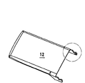
図1は、PDA(および他の電気構成要素)および旋回カバー12を受けるよう構成されている枠10を示す。枠10は、PDAを内部に設置できるように構成された第1および第2の対の対向側壁14、16を備えている。PDAは、固定点18を通過してPDAの下側に入るよう構成された4個のねじコネクタ(図示せず)により枠10に固定されるよう構成されている。カバー12は、一対の蝶番組立体20により枠10に蝶番式に接続されるよう構成されている。蝶番組立体20の構成は図3および図6に最も良く示されている。
【0021】
各蝶番組立体20は、主本体22aおよび拡大ヘッド22bを有するボス部材22を備えている。ボス部材22は、取付け板24と一体に形成されるか、またはそれに取付けられている。取付け板24は、第1の側壁14の一方の内側26に設置されるよう構成されている。取付け板24には側壁14を貫く孔29と軸方向に整列するよう形成されている円形孔28がある。
【0022】
蝶番組立体20はまた、ボス部材22およびカバー接続部材32に取付けられるよう構成された捻りばね30を備えている。カバー接続部材32は、カム36および係合部材38を組み込む第1の部分34を備えている。カム36は、第1および第2の対の対向カム面40、42により形成されている。各隣接する第1および第2のカム面40、42の間にあるのは曲がった接合表面44である。カム36、第1の対の対向カム面40、第2の対の対向カム面42、および接合表面44の機能を下に更に詳細に説明する。
【0023】
カバー接続部材32の第2の端部は、第1および第2の円筒形部分46、48を備えている。第1の円筒形部分46は、カム36に隣接して設置され、その直径は第2の円筒形部分48の直径と比較して小さい。第1および第2の円筒形部分46、48の直径は、それぞれが孔28、29に嵌入して接続部材32が孔28、29を内側に完全に通過しないようにし、一方接続部材32をその中でなおも自由に回転させるようになっている。
【0024】
捻りばね30は、円形部分30aおよび実質的に互いに平行な一対の細長い部分30bを備えている。捻りばね30の円形部分30aは、ボス部材22の上方を通過してボス部材22の主体22aに設置できるような大きさになっている。ボス部材22の拡大ヘッド22bは、捻りばね30がボス部材22から偶然に外れないようにする大きさになっている。
【0025】
蝶番組立体20を第1の側壁14に組みつけるには、接続部材32を最初、それぞれ取付け板24および側壁14に形成された軸方向整列孔28、29の中に設置しなければならない。接続部材32を孔28、29の中に正しく設置すると、カム36および係合部材38が取付け板24の垂直平面を越えて突出する。捻りばね30の細長い部分30bはこのときカム36の対向表面42に対して突出するように設置される。その後、捻りばね30の円形部分30aがボス部材22の拡大ヘッド22bの上方に押上げられ、捻りばね30の円形部分30aがボス部材22の主体22aの周りに設置されるようになる。図3は、第1のカム面40のそれぞれの一つに対して設置された捻りばね30の細長い部分30bの各々を明瞭に示している。
【0026】
図4および図5に最も良く示してあるように、カバー12は、各々がそれに取付けられ、または形成されているコネクタ52を有する従属蝶番部材50を備えている。図5に示したように、この実施形態のコネクタ52は、「一の字」雄形コネクタ52である。雄形コネクタ52は、接続部材32の第2の円筒形部分48の端面48aに形成された相補形状の雌形コネクタ54の中に受けられるよう構成されている。相補形状の雌形コネクタ54は図8に最も良く図示されている。
【0027】
図1に示したように、蝶番組立体20は、第1の側壁14の各々の上部分に接続されるよう構成されている。蝶番部材50の付いたカバー12を次に、雄形コネクタ52がそれぞれの側壁14の上方を通るように蝶番部材50の各々を外側に曲げることにより枠10に接続する。雄形コネクタ52を次にそのそれぞれの接続部材32の端面48aに形成されたそのそれぞれの雌形コネクタ54の中に設置する。図3は、一つの蝶番部材50のそのそれぞれの蝶番組立体20への接続を示している。カバー12は、図3に示したように、閉じた位置にある。
【0028】
カバー12が閉じた位置にあるとき、捻りばね30の細長い部分30bはカム36のそれぞれの第1の表面40に接触し、カム36は、水平に対してほぼ30度の所定角度にある。これを図8に最も良く示してある。
【0029】
ユーザがカバー12を回転して開いたまたは使用時位置に移動させると、雄形コネクタ52と接続部材32との間の係合により接続部材32が孔28、29の中で回転する。この事象が発生するにつれて、カム36のカム面40の第1の対も回転する。しかし、接続部材32のこの回転移動は、捻りばね30の細長い部分30bと第1の対のカム面40との間の接触により阻止される。したがって、捻りばね30によるこの阻止によりカバー12が閉じた位置に戻る傾向がある。このためカバー12に対する「自動閉鎖」特徴が得られる。カバー12が使用時位置の方に続いて回転すると、この阻止に打ち勝って捻りばね30の細長い部分30bがカム36の曲がった接合面44と接触し始めるようになる。この事象が発生するとき、カム36が中立位置またはトグル位置に達したという。カバー12をこのとき更に使用時位置の方に回転させれば、接続部材32も、捻りばね30の細長い部分30bがカム36の第2の対のカム面42と接触するまで、回転する。捻りばね30の細長い部分30bがカム36の第2の対のカム面42と接触すると、カバー12は、開いたまたは使用時位置に敏速に移動する。これにより「自動開放」特徴を有するカバー12が生ずる。
【0030】
図11に最も良く示したように、枠10の側壁14の外側にストッパ60が設けられている。ストッパ60は、カバー12が水平から120度の傾斜に達したら、カバー12が移動しないように、カバー12の一部12dと係合するよう構成されている。ストッパ60がカバー12のそれ以上の旋回移動を阻止するので、捻りばね30の抵抗力がカバー12を更に開こうとし、それによりカバー12が開いたまたは使用時位置にしっかり保持される。
【0031】
上の説明から、カム36の構成およびその、捻りばね30の細長い部分30bとの関係が、捻りばね30がカム36および接続されたカバー12を、カバー12が中立位置またはトグル位置を過ぎて回転するまで閉じた位置に保持する傾向があるようになっていることが認識されよう。カバー12の回転を、カム36が中立位置またはトグル位置に達する前に停止させれば、カバー12は、閉じた位置に敏速に移動する。しかし、カバー12をこの中立位置またはトグル位置を過ぎて回転させると、捻りばね30の細長い部分30bが第2のカム面42と接触し、したがってカバー12が完全に開いた位置まで持ち上げられる。カバー12は捻りばね30の作用により完全に開いた位置または使用時位置に保持されることになる。
【0032】
本発明の特に好適な実施形態では、カバー12を水平に対してほぼ120度の角度に完全に開くことができる。カム36の中立位置またはトグル位置は、第1の対の対向表面40が水平に対して90度の角度にあるとき生ずる。これを図10に最も良く示してある。
【0033】
カバー12を開いたとき所要の触覚を得るためには、または換言すれば所要の開きの滑らかさを達成するためには、図9に最も良く示したカム比率を好適には
L/B=3.4/1.3=2.6
とすべきである。
【0034】
上述の蝶番組立体20は、構造が簡単で且つ極小数の構成要素部品を使用しているので、有利であると考えられる。更に、この種の蝶番組立体を備えてもPDA枠の軸方向寸法が増大しない。これは、PDAとカバーとの組合せの大きさを可能なかぎり小さく維持できるようにするのに極めて重要である。
【0035】
本発明の一実施形態の蝶番組立体20は、それによりカバー12を閉じた位置または開いた位置に維持できる確実な方法を与え、カバーを所要位置に確実に維持するのために別のロックまたは留め具を必要としない。更に、蝶番組立体20は、軽量のプラスチック材料から作られ、したがって装置の全体の重量を大幅に増大させることはない。
【0036】
当業者は、カバー12の雄形コネクタ52が「一の字形」構成を有するとして説明したが、他の構成が考えられることを認識するであろう。たとえば、コネクタ52は「十字形」または「星形」の構成を採用できる。また、蝶番部材50のコネクタ52を接続部材32に形成された雄形コネクタ54を受けるよう構成された雌形コネクタとして良いことが考えられる。コネクタ52の構成に加えられる唯一つの制限は、コネクタ52がカバー12の回転移動により接続部材32の回転移動が生ずるように接続部材32の相補形状コネクタと正しく係合しなければならないということである。
【0037】
当業者はまた、蝶番部材50を十分柔軟にして、コネクタ52が側壁14の上方を通過でき、次いで接続部材32に形成された相補形状コネクタ54の中に設置できるように外側に曲がることができなければならないことを認識するであろう。
【0038】
前に説明した蝶番組立体をプラグアンドプレイ用(差し込んだら直ぐに使えるように)に修正できることが考えられている。図12に示したように、このようなプラグアンドプレイ組立体100は、取付け板24'、ボス部材22'、捻りばね30'、およびカバー接続部材32'を備えている。これら構成要素を、簡単に枠10'に差し込み、または差し入れるように予め組立る。枠10'は取付け板24'を受け、これと係合する形状の、適切な位置に形成された溝105または孔を備えている。
【0039】
ここに説明した実施形態は好適であるが、本明細書から、当業者が作成する種々の代案、修正案、変体、または改良案が「特許請求の範囲」により規定されている本発明の範囲内にあることが認識されるであろう。
【0040】
なお、この発明は例として次の実施態様を含む。
【0041】
[1] カバーを装置に接続するための蝶番組立体において、片寄せ手段を取付けるよう構成されているボス部材と、前記装置に回転可能に取付けるよう構成され、前記片寄せ手段の少なくとも一部と相互作用するよう構成されたカム手段を備えている第1の端部および前記カバーを接続するよう構成された第2の部分を有するカバー接続部材と、を備えたことを特徴とするもの。
【0042】
[2] 上記[1]に記載の蝶番組立体において、前記片寄せ手段が捻りばねを備えていることを特徴とするもの。
【0043】
[3] 上記[2]に記載の蝶番組立体において、前記装置が側壁を備え、前記カバー接続部材が前記側壁の孔を通して突出していることを特徴とするもの。
【0044】
[4] 上記[2]に記載の蝶番組立体において、前記捻りばねが円形部分と、互いに実質的に平行な一対の細長い部分とを備えていることを特徴とするもの。
【0045】
[5] 上記[4]に記載の蝶番組立体において、前記ボス部材が本体部分および拡大端部を備え、前記捻りばねが、その円形部分が前記ボス部材の前記本体部分に設置されるように、前記ボス部材に取付けられるよう構成されている、ことを特徴とするもの。
【0046】
[6] 上記[1]に記載の蝶番組立体において、前記接続部材手段の前記カム手段が第1および第2の対を成す対向平行表面を備えていることを特徴とするもの。
【0047】
[7] 上記[6]に記載の蝶番組立体において、前記第1および第2の対の対向表面が互いに垂直であることを特徴とするもの。
【0048】
[8] 上記[6]に記載の蝶番組立体において、各隣接する第1および第2の表面が曲がった接合表面により接合されていることを特徴とするもの。
【0049】
[9] 上記[2]に記載の蝶番組立体において、前記接続部材の前記第1の部分が、前記接続部材が前記側壁に形成された孔から偶然に外れないようにするために前記捻りばねに係合する手段をも備えていることを特徴とするもの。
【0050】
[10] 上記[9]に記載の蝶番組立体において、前記係合手段が、前記カム手段に隣接して前記接続部材が前記側壁に形成された孔を通して戻らないようにするように前記捻りばねの一部に接触するよう構成された拡大部分を備えていることを特徴とするもの。
【0051】
[11] 上記[1]に記載の蝶番組立体において、前記接続部材の第2の部分が第1および第2の円筒形部分を備えていることを特徴とするもの。
【0052】
[12] 上記[10]に記載の蝶番組立体において、前記装置の側壁に設けられた孔が前記接続部材の前記第1および第2の円筒形部分を受けるよう構成され、前記接続部材がその中で回転できるようにされていることを特徴とするもの。
【0053】
[13] 上記[11]に記載の蝶番組立体において、前記第1の円筒形部分がカム手段に隣接して設置されていることを特徴とするもの。
【0054】
[14] 上記[11]に記載の蝶番組立体において、前記第1の円筒形部分の直径が前記第2の円筒形部分の直径と比較して小さいことを特徴とするもの。
【0055】
[15] 上記[11]に記載の蝶番組立体において、前記カバーおよび、前記接続部材の前記第2の円筒形部分端部が、前記カバーを前記接続部材に接続できるようにする相補形状コネクタを備えていることを特徴とするもの。
【0056】
[16] 上記[15]に記載の蝶番組立体において、前記相補形状コネクタが雄形および雌形のコネクタを備えていることを特徴とするもの。
【0057】
[17] 上記[16]に記載の蝶番組立体において、前記雄型コネクタが前記カバーに設置され、「十字形」まは「一の字形」の断面構成を採用していることを特徴とするもの。
【0058】
[18] 上記[15]に記載の蝶番組立体において、前記カバーにある前記コネクタは、前記カバーから突出している蝶番部材に設置されていることを特徴とするもの。
【0059】
[19] 上記[1]に記載の蝶番組立体において、前記ボス部材および前記接続部材がプラスチック材料から作られていることを特徴とするもの。
【0060】
[20] 対向側壁を有する装置、前記装置に接続するよう設置されているカバーと、少なくとも一つの蝶番組立体とを備えている組立体において、前記少なくとも一つの蝶番組立体が、捻りばねを取付けるよう構成されているボス部材と、前記側壁の一方に取付けるよう構成され、前記捻りばねの少なくとも一部と相互作用するよう構成されたカム手段を備えている第1の部分および前記カバーを接続するよう構成されている第2の部分を有するカバー接続部材と、を備えていることを特徴とするもの。
【0061】
[21] 上記[20]に記載の組立体において、一対の蝶番組立体を備えていることを特徴とするもの。
【0062】
[22] カバーを装置に接続するための蝶番組立体において、前記カバーは完全に開いた位置と完全に閉じた位置との間を移動するよう構成され、前記蝶番組立体は、前記カバーを前記装置に接合するよう構成されたカバー接続部材、および前記接続部材の一部と係合して前記カバーを、前記接続部材の向きにより、前記完全に開いた位置または前記完全に閉じた位置のいずれかの方に片寄せるよう設置されている片寄せ手段を備えている、ことを特徴とするもの。
【0063】
[23] 上記[22]に記載の蝶番組立体において、前記接続部材がカム手段を備え、前記片寄せ手段がそれと係合するよう構成されていることを特徴とするもの。
【0064】
[24] 上記[23]に記載の蝶番組立体において、前記片寄せ手段が捻りばねを備えていることを特徴とするもの。
【0065】
[25] 上記[1]に記載の蝶番組立体において、前記カム手段が中立位置またはトグル位置を備え、前記カム手段が中立位置またはトグル位置を越えて回転すれば、前記カバー接続手段が前記カバーを完全に開いた位置に移動させるようになっていることを特徴とするもの。
【0066】
[26] 上記[25]に記載の蝶番組立体において、前記カム手段の前記中立位置またはトグル位置が、前記カム手段のカム面が水平に対してほぼ90度の角度に設置されたとき生ずることを特徴とするもの。
【0067】
[27] 上記[25]に記載の蝶番組立体において、前記カバーが完全に開いた位置にあるとき、前記カバーが水平に対してほぼ120度の角度にあることを特徴とするもの。
【0068】
[28] 上記[22]に記載の蝶番組立体において、前記対向側壁の少なくとも一方に取付けられ、前記カバーが、必要な完全に開いた位置に到達したら、移動しないようにするストッパを備えていることを特徴とするもの。
【0069】
[29] 上記[22]に記載の蝶番組立体において、前記装置を保持するよう設けられた枠の側壁に形成された孔に取付けられるよう構成されていることを特徴とするもの。
【図面の簡単な説明】
【図1】PDAの枠およびそれに取付ける前のカバーの斜視図である。
【図2】PDAに取付けられ、閉じた位置にあるカバーの斜視図である。
【図3】図2に示した円形部分の拡大図である。
【図4】図1に示したカバーの斜視図である。
【図5】図4に示した円形部分の拡大図である。
【図6】接続部材、捻りばね、およびPDA枠の一部を示す組立図である。
【図7】カバーの雄形接続を取付けるよう構成されている雌形接続を示す接続部材の端面図である。
【図8】カバーが閉じた位置にあるときのカムの角位置の詳細図である。
【図9】カムの第1および第2のカム面の好適比率の詳細を示す参考図である。
【図10】カバーが完全に開いた位置にあるときのカムの角位置の詳細を示す。
【図11】枠の部分側面図であり、ストッパを示す。
【図12】蝶番組立体の「プラグアンドプレイ」実施形態の詳細を示す。
【符号の説明】
12 カバー
14 側壁
16 側壁
20 蝶番組立体
22 ボス
22b ボスの拡大部分
28 孔
30 捻りばね
30a 捻りばねの円形部分
30b 捻りばねの細長い部分
32 カバー接続部材
36 カム
40 カムの平行表面
42 カムの平行表面
44 曲がった接合面
46 カバー接続部材の円筒形部分
48 カバー接続部材の円筒形部分
60 ストッパ[0001]
BACKGROUND OF THE INVENTION
The present invention relates to a butterfly program solid for a cover, and more particularly to a butterfly program solid used to connect a cover to a personal digital assistant or similar frame.
[0002]
[Prior art]
Most personal digital assistants (PDAs) are provided with a plastic protective cover on the screen to prevent damage. When using such a cover, it is important that the cover can be securely held in an open or closed position. For this purpose, certain cover devices for PDAs are provided with fasteners or stoppers that hold the cover in the required open or closed position. However, these fasteners tend to wear out throughout and continuous use, thereby preventing the cover from being held in the open position. This is very troublesome for the user because the user's PDA screen becomes difficult to see if the cover is removed.
[0003]
US Pat. No. 5,996,178 describes a hinge suitable for use in a foldable electronic device. The hinge device described in US Pat. No. 5,996,178 relies on axial force from a compression spring to rotate the cover. This hinge device is very complex and has a significant number of parts. This hinge arrangement also requires a separate axial space to install the hinge arrangement.
[0004]
[Problems to be solved by the invention]
The present invention provides an improved butterfly program for use with a cover for a PDA or similar that has a small number of component parts that securely hold the cover in the required open or closed position and is simple to configure. The purpose is to provide a solid.
[0005]
[Means for Solving the Problems]
According to a first aspect of the present invention, there is provided a butterfly program body for connecting a cover to a device, the assembly comprising a boss member configured to attach a biasing means, and the device. A cover connecting member configured to be attached and configured to connect the cover and a first end with cam means configured to interact with at least a portion of the biasing means. A cover connecting member having a second portion.
[0006]
Preferably, the biasing means is a torsion spring.
[0007]
Preferably, the device has a side wall and the cover connecting member is configured to protrude through a hole in the side wall.
[0008]
Preferably, the torsion spring comprises a circular portion and a pair of elongated portions substantially parallel to each other. Instead of a torsion spring with a circular part, an elliptical part can also be provided.
[0009]
The boss member preferably comprises a body portion and an enlarged end. The torsion spring is configured to be attached to the boss member such that the circular portion is installed in the main body portion of the boss member. The enlarged portion of the boss member helps to prevent the torsion spring from coming off the boss member.
[0010]
Preferably, the cam means of the connecting member means comprises first and second pairs of opposing parallel surfaces. The first and second pairs of opposing surfaces are perpendicular to each other and are preferably joined by a curved joining surface at each adjacent first and second surface.
[0011]
The first portion of the connecting member also includes means for engaging the torsion spring to prevent the connecting member from accidentally coming out of a hole formed in the side wall. The engagement means preferably comprises an enlarged portion adjacent to the cam means for contacting at least one elongated portion of the torsion spring and preventing the connecting member from returning through a hole formed in the side wall.
[0012]
The second part of the connecting member preferably comprises first and second cylindrical parts. A hole provided in the side wall of the device is preferably configured to receive the first and second cylindrical portions of the connecting means so that the connecting means can rotate therein.
[0013]
The configurations of the first and second cylindrical portions and the holes are configured so that no connecting member passes through the holes.
[0014]
The first cylindrical portion is preferably located adjacent to the cam means and its diameter is small compared to the diameter of the second cylindrical portion.
[0015]
The cover and the end of the second cylindrical portion of the connecting member are provided with complementary shaped connectors that allow the cover to be connected to the connecting member. Complementary shaped connectors preferably include male and female connectors. The male connector is preferably placed on the cover and has a “cross-shaped” or “one-shaped” cross-sectional configuration. The male and female connectors on the cover are preferably formed on a hinge member protruding from the cover. The cover preferably comprises a pair of hinge members, each hinge member having a connector attached or formed thereto, the connector being received by a respective complementary connection member formed on a respective side wall of the device. It is configured to be
[0016]
The boss member and the connecting member are preferably made of a plastic material. The cover is also preferably made from a plastic material.
[0017]
According to a second aspect of the present invention, there is provided an assembly comprising a device having opposing sidewalls, a cover configured to connect to the device, and at least one butterfly program solid, At least one butterfly program body includes a boss member configured to attach a torsion spring and a cover connection member configured to attach to one of the side walls, the connection member including at least a portion of the torsion spring. A first portion having cam means configured to interact and a second portion configured to connect the cover.
[0018]
Preferably, the assembly comprises a pair of butterfly program cubes.
[0019]
According to a third aspect of the present invention, there is provided a butterfly program body for connecting a cover to the device, the cover configured to move between a fully open position and a fully closed position. The butterfly program body is configured to engage the cover connecting member configured to join the cover to the device, and a part of the connecting member to open the cover completely according to the orientation of the connecting member. Biasing means for biasing toward the position or the fully closed position.
[0020]
DETAILED DESCRIPTION OF THE INVENTION
FIG. 1 shows a
[0021]
Each butterfly program solid 20 includes a
[0022]
The
[0023]
The second end of the
[0024]
The
[0025]
In order to assemble the
[0026]
As best shown in FIGS. 4 and 5, the
[0027]
As shown in FIG. 1, the butterfly program solid 20 is configured to be connected to the upper portion of each of the
[0028]
When the
[0029]
When the user rotates and moves the
[0030]
As best shown in FIG. 11, a
[0031]
From the above description, the configuration of the
[0032]
In a particularly preferred embodiment of the invention, the
[0033]
In order to obtain the required tactile sensation when the
Should be.
[0034]
The butterfly program solid 20 described above is considered advantageous because it is simple in construction and uses a minimal number of component parts. Furthermore, even if this type of butterfly program solid is provided, the axial dimension of the PDA frame does not increase. This is extremely important in order to keep the size of the PDA and cover combination as small as possible.
[0035]
The
[0036]
One skilled in the art will recognize that the
[0037]
One skilled in the art can also bend the
[0038]
It is considered that the butterfly program described above can be modified for plug and play (so that it can be used immediately after being inserted). As shown in FIG. 12, the plug and play assembly 100 includes a mounting
[0039]
While the embodiments described herein are preferred, the scope of the invention is defined by the following claims from which various alternatives, modifications, variations, or improvements made by those skilled in the art are defined by the claims. It will be recognized that it is within.
[0040]
In addition, this invention includes the following embodiment as an example.
[0041]
[1] In a butterfly program body for connecting a cover to a device, a boss member configured to attach a biasing means, a boss member configured to be rotatably attached to the device, and at least a part of the biasing means; A cover connecting member having a first end having cam means configured to interact and a second portion configured to connect the cover.
[0042]
[2] The butterfly program solid according to [1] above, wherein the biasing means includes a torsion spring.
[0043]
[3] The butterfly program solid according to [2], wherein the device includes a side wall, and the cover connecting member protrudes through a hole in the side wall.
[0044]
[4] The butterfly program solid according to [2], wherein the torsion spring includes a circular portion and a pair of elongated portions substantially parallel to each other.
[0045]
[5] In the butterfly program body described in [4] above, the boss member includes a main body portion and an enlarged end portion, and the torsion spring is arranged such that the circular portion is installed on the main body portion of the boss member. The boss member is configured to be attached to the boss member.
[0046]
[6] The butterfly program solid according to [1] above, wherein the cam means of the connecting member means includes opposed parallel surfaces forming first and second pairs.
[0047]
[7] The butterfly program solid according to [6] above, wherein the opposing surfaces of the first and second pairs are perpendicular to each other.
[0048]
[8] The butterfly program solid according to [6] above, wherein the adjacent first and second surfaces are joined by curved joining surfaces.
[0049]
[9] In the butterfly program body according to [2], the torsion spring prevents the first portion of the connection member from accidentally coming off from a hole formed in the side wall. It is also provided with a means for engaging with.
[0050]
[10] In the butterfly program body according to [9], the torsion spring prevents the engaging means from returning through the hole formed in the side wall adjacent to the cam means. Characterized in that it comprises an enlarged portion configured to contact a portion of the.
[0051]
[11] The butterfly program solid according to [1] above, wherein the second portion of the connection member includes first and second cylindrical portions.
[0052]
[12] In the butterfly program body described in [10] above, a hole provided in a side wall of the device is configured to receive the first and second cylindrical portions of the connection member, and the connection member is Characterized by being able to rotate inside.
[0053]
[13] The butterfly program solid according to [11], wherein the first cylindrical portion is disposed adjacent to the cam means.
[0054]
[14] The butterfly program solid according to [11] above, wherein the diameter of the first cylindrical portion is smaller than the diameter of the second cylindrical portion.
[0055]
[15] The butterfly program solid according to [11] above, wherein the cover and the second cylindrical partial end of the connection member are connected to the connection member so that the cover can be connected to the connection member. It is characterized by having.
[0056]
[16] The butterfly program solid according to [15], wherein the complementary connector includes a male connector and a female connector.
[0057]
[17] The butterfly program solid according to [16] above, wherein the male connector is installed on the cover and adopts a cross-shaped configuration of “cross” or “one-letter” thing.
[0058]
[18] The butterfly program solid according to [15], wherein the connector in the cover is installed on a hinge member protruding from the cover.
[0059]
[19] The butterfly program solid according to [1], wherein the boss member and the connection member are made of a plastic material.
[0060]
[20] In an assembly comprising a device having opposing side walls, a cover installed to connect to the device, and at least one butterfly program solid, the at least one butterfly program solid mounts a torsion spring A boss member configured in such a manner as to connect the cover and a first portion comprising cam means configured to attach to one of the side walls and configured to interact with at least a portion of the torsion spring; And a cover connecting member having a second part configured as described above.
[0061]
[21] The assembly according to [20], wherein the assembly includes a pair of butterfly program solids.
[0062]
[22] In a butterfly program body for connecting a cover to the device, the cover is configured to move between a fully open position and a fully closed position, and the butterfly program body is configured to move the cover to the device. A cover connecting member configured to be joined to the device, and engaging the part of the connecting member to position the cover in either the fully open position or the fully closed position, depending on the orientation of the connecting member. It is provided with a side-by-side means installed so as to be side-by-side.
[0063]
[23] The butterfly program solid according to [22], wherein the connecting member includes a cam means, and the biasing means is configured to engage with the cam means.
[0064]
[24] The butterfly program solid according to [23], wherein the biasing means includes a torsion spring.
[0065]
[25] In the butterfly program solid according to [1] above, if the cam means has a neutral position or a toggle position, and the cam means rotates beyond the neutral position or the toggle position, the cover connecting means becomes the cover Characterized in that it is designed to be moved to a fully open position.
[0066]
[26] In the butterfly program solid described in [25] above, the neutral position or toggle position of the cam means occurs when the cam surface of the cam means is installed at an angle of approximately 90 degrees with respect to the horizontal. It is characterized by.
[0067]
[27] The butterfly program solid according to [25], wherein the cover is at an angle of approximately 120 degrees with respect to the horizontal when the cover is in a fully opened position.
[0068]
[28] In the butterfly program body described in [22] above, the butterfly program solid body is provided with a stopper which is attached to at least one of the opposing side walls and prevents the cover from moving when it reaches a necessary fully opened position. It is characterized by that.
[0069]
[29] The butterfly program solid according to [22], wherein the butterfly program solid body is configured to be attached to a hole formed in a side wall of a frame provided to hold the device.
[Brief description of the drawings]
FIG. 1 is a perspective view of a PDA frame and a cover before being attached to the PDA frame.
FIG. 2 is a perspective view of the cover attached to the PDA and in a closed position.
FIG. 3 is an enlarged view of a circular part shown in FIG. 2;
4 is a perspective view of the cover shown in FIG. 1. FIG.
FIG. 5 is an enlarged view of a circular portion shown in FIG.
FIG. 6 is an assembly view showing a connection member, a torsion spring, and a part of a PDA frame.
FIG. 7 is an end view of a connecting member showing a female connection configured to attach a male connection of a cover.
FIG. 8 is a detailed view of the angular position of the cam when the cover is in the closed position.
FIG. 9 is a reference diagram showing details of a preferred ratio of the first and second cam surfaces of the cam.
FIG. 10 shows details of the angular position of the cam when the cover is in the fully open position.
FIG. 11 is a partial side view of the frame, showing a stopper.
FIG. 12 shows details of a “plug and play” embodiment of a butterfly program solid.
[Explanation of symbols]
12
Claims (27)
円形部分と、互いに略平行な一対の細長い部分とを有する片寄せ手段と、
前記片寄手段の前記円形部分を設置柱上に配置することによって、前記片寄せ手段がその上に設置される前記設置柱を有するボス部材付き取付け板と、
前記装置の側壁の孔を通って延び、相補形状の雄型及び雌型コネクタを用いて前記カバーに接続され、前記設置された前記片寄せ手段の前記細長い部分によって挟まれるカム手段を有する接続部材とを備え、
前記カム手段を挟むことによって、前記カバーは閉じられているときには開かれることが妨げられ、前記カバーは開かれているときには閉じられることが妨げられることを特徴とする蝶番組立体。In the butterfly program to connect the cover to the device,
A circular portion, a piece Yosete stage having a substantially parallel pair of elongated portions to each other,
A mounting plate with a boss member having the installation column on which the biasing unit is installed by arranging the circular portion of the offset unit on the installation column;
A connecting member having a cam means extending through a hole in the side wall of the device, connected to the cover using complementary male and female connectors and sandwiched by the elongated portion of the installed biasing means And
By sandwiching the cam means, the butterfly program body is prevented from being opened when the cover is closed, and prevented from being closed when the cover is opened .
前記接続部材は両方の前記孔を通ることを特徴とする請求項1に記載の蝶番組立体。 The mounting plate with the boss member has a hole that is smaller than the hole in the side wall and aligns with the hole in the side wall,
The butterfly program body according to claim 1 , wherein the connecting member passes through both the holes .
前記カム手段が前記片寄せ部材の前記細長い部分によって挟まれているときに、前記第2の拡大部分は、前記接続部分が前記側壁及び前記ボス部材付き取付け板の前記孔から外れるのを妨げることを特徴とする請求項8に記載の蝶番組立体。The connecting member has a second enlarged portion passing through the hole of the attachment plate with the side wall and the boss member adjacent to the cam means,
When the cam means is sandwiched by the elongated portion of the biasing member, the second enlarged portion prevents the connecting portion from coming out of the side wall and the hole of the mounting plate with the boss member. The butterfly program solid according to claim 8.
前記少なくとも一つの蝶番組立体が、円形部分及び二つの細長い部分を有する捻りばねと、
孔、及び前記捻りばねがその上に取付けられる設置柱を有するボス部材付き取付け板と、
前記装置の側壁の孔、及び前記ボス部材付き取付け板の前記孔を通って延び、相補形状の雄型及び雌型コネクタを用いて前記カバーに接続され、前記設置された前記捻りばねの前記細長い部分によって挟まれるカム手段を有する接続部材とを備え、
前記カム手段を挟むことによって、前記カバーは閉じられているときには開かれることが妨げられ、前記カバーは開かれているときには閉じられることが妨げられることを特徴とする組立体。An assembly comprising: a device having opposing side walls; and a cover configured to be connected to the device by at least one butterfly program body;
The at least one butterfly program body comprises a torsion spring having a circular portion and two elongated portions ;
A mounting plate with a boss member having a hole and an installation post on which the torsion spring is mounted ;
The elongate of the installed torsion spring extending through the hole in the side wall of the device and through the hole in the mounting plate with the boss member and connected to the cover using complementary male and female connectors A connecting member having cam means sandwiched between the parts,
By sandwiching the cam means, the cover is prevented from being opened when it is closed, and the cover is prevented from being closed when it is opened .
前記カバーは完全に開いた位置と完全に閉じた位置との間を移動するように構成され、
前記蝶番組立体は、
前記カバーに接続され、前記装置の側壁の孔を通って延び、相補形状の雄型及び雌型コネクタを用いて前記カバーに接続される接続部材と、
前記側壁の内側に取り付けられ、円形部分と、互いに略平行に延びる一対の細長い部分とを有する片寄せ手段とを備え、
前記片寄せ手段の前記細長い部分が前記接続部分のカム手段を挟み、これにより、前記カバーを、前記接続部材の向きにより、前記完全に開いた位置または前記完全に閉じた位置のいずれかの方に片寄せることを特徴とする蝶番組立体。In the butterfly program to connect the cover to the device,
The cover is configured to move between a fully open position and a fully closed position;
The butterfly program
A connecting member connected to the cover, extending through a hole in the side wall of the device, and connected to the cover using complementary male and female connectors;
A biasing means attached to the inside of the side wall and having a circular portion and a pair of elongated portions extending substantially parallel to each other;
The elongate portion of the biasing means sandwiches the cam means of the connecting portion, whereby the cover is either in the fully open position or the fully closed position depending on the orientation of the connecting member. hinge assembly, wherein the Turkey biased to.
前記装置は第1及び第2の対になった対向する側壁を有しており、
前記蝶番組立体は、
前記第1の側壁の一つに取り付けられるように構成されるボス部材付き取付け板と、
前記ボス部材付き取付け板に取り付けられるように構成される片寄せ手段と、
前記第1の側壁の一つに形成された孔を通って延び、前記片寄せ手段によって挟まれるカム手段を有する接続部材と、を有しており、
前記接続部材は、相補形状の雄型及び雌型コネクタを用いて前記カバーに接続され、
前記カム手段を挟むことによって、前記カバーは閉じられているときには開かれることが妨げられ、前記カバーは開かれているときには閉じられることが妨げられることを特徴とする蝶番組立体。In the butterfly program to connect the cover to the device,
The device has first and second pairs of opposing sidewalls;
The butterfly program
A mounting plate with a boss member configured to be mounted on one of the first side walls;
Biasing means configured to be attached to the mounting plate with the boss member;
Extends through the first one in a hole formed in the side wall, has a a connection member having a cam means sandwiched by said biasing means,
The connection member is connected to the cover using complementary male and female connectors,
By sandwiching the cam means, the butterfly program body is prevented from being opened when the cover is closed, and prevented from being closed when the cover is opened .
Applications Claiming Priority (2)
| Application Number | Priority Date | Filing Date | Title |
|---|---|---|---|
| US09/839,391 US6539580B2 (en) | 2001-04-20 | 2001-04-20 | Hinge assembly for a cover |
| US09/839391 | 2001-04-20 |
Publications (3)
| Publication Number | Publication Date |
|---|---|
| JP2002368445A JP2002368445A (en) | 2002-12-20 |
| JP2002368445A5 JP2002368445A5 (en) | 2005-06-30 |
| JP4071528B2 true JP4071528B2 (en) | 2008-04-02 |
Family
ID=25279608
Family Applications (1)
| Application Number | Title | Priority Date | Filing Date |
|---|---|---|---|
| JP2002115906A Expired - Fee Related JP4071528B2 (en) | 2001-04-20 | 2002-04-18 | Cover butterfly program |
Country Status (3)
| Country | Link |
|---|---|
| US (1) | US6539580B2 (en) |
| EP (1) | EP1251224A1 (en) |
| JP (1) | JP4071528B2 (en) |
Families Citing this family (10)
| Publication number | Priority date | Publication date | Assignee | Title |
|---|---|---|---|---|
| US7609512B2 (en) * | 2001-11-19 | 2009-10-27 | Otter Products, Llc | Protective enclosure for electronic device |
| US20030100338A1 (en) * | 2001-11-28 | 2003-05-29 | Peter Lee | Personal digital assistant cover with an integrated keypad |
| DE10208040A1 (en) | 2002-02-25 | 2003-09-04 | Bsh Bosch Siemens Hausgeraete | Hinge connection and container equipped with it |
| US20040020012A1 (en) * | 2002-08-02 | 2004-02-05 | Gupte Sheel A. | Self-contained hinge for flip-style device |
| US20050220294A1 (en) * | 2004-02-02 | 2005-10-06 | Amphenol-T&M Antennas | Push-button hinge for handheld devices |
| US20060193469A1 (en) * | 2004-06-08 | 2006-08-31 | Tony Kfoury | Parallel plane rotation hinge for a portable device |
| KR20070027576A (en) | 2004-06-08 | 2007-03-09 | 암페놀 티 앤드 엠 안테나즈 | Parallel plane rotation hinge for a portable device |
| EP2080080B1 (en) | 2006-11-08 | 2017-03-29 | TTE Technology, Inc. | Multi-purpose flat panel display cover |
| TWM319568U (en) * | 2006-11-27 | 2007-09-21 | Ks Terminals Inc | Card connection apparatus and its applications about digital products |
| CN101945553A (en) * | 2009-07-03 | 2011-01-12 | 深圳富泰宏精密工业有限公司 | Position-limiting structure and portable electronic device with same |
Family Cites Families (16)
| Publication number | Priority date | Publication date | Assignee | Title |
|---|---|---|---|---|
| JPS5645093Y2 (en) | 1975-09-12 | 1981-10-21 | ||
| JPH057629Y2 (en) * | 1986-08-29 | 1993-02-25 | ||
| IT218174Z2 (en) | 1988-06-27 | 1992-04-08 | Zanussi A Spa Industrie | HINGE FOR DOOR OF HOUSEHOLD APPLIANCES. |
| WO1991013507A1 (en) * | 1990-02-27 | 1991-09-05 | Fujitsu Limited | Portable telephone |
| JPH0491541A (en) * | 1990-08-07 | 1992-03-25 | Fujitsu Ltd | Handset for telephone set |
| JP2856263B2 (en) | 1990-09-07 | 1999-02-10 | 富士通株式会社 | Mobile phone |
| ES2027930A6 (en) * | 1991-02-15 | 1992-06-16 | Ind Techno Matic Sa | Fixing spring for hinges of sun visors of motor vehicles. |
| KR0138235B1 (en) * | 1994-08-23 | 1998-07-01 | 김광호 | Handphone |
| US5715575A (en) | 1995-03-13 | 1998-02-10 | Kato Spring Works Co., Ltd. | Hinge device |
| US5666694A (en) * | 1995-09-28 | 1997-09-16 | Hewlett-Packard Company | Hinge arrangement |
| US5661797A (en) * | 1995-11-01 | 1997-08-26 | Nokia Mobile Phones Ltd. | Hinge mechanism for cellular transceiver housing |
| JP2895009B2 (en) * | 1996-11-15 | 1999-05-24 | 株式会社加藤スプリング製作所 | Hinge device |
| US5996178A (en) | 1997-10-15 | 1999-12-07 | Motorola, Inc. | Hinge suitable for use in a foldable device |
| JP2906346B1 (en) * | 1998-02-09 | 1999-06-21 | スガツネ工業株式会社 | Hinge device |
| GB2337790B (en) | 1998-05-29 | 2002-12-31 | Nokia Mobile Phones Ltd | Hinge mechanism |
| JP2000320535A (en) * | 1999-05-12 | 2000-11-24 | Strawberry Corporation:Kk | Hinge device |
-
2001
- 2001-04-20 US US09/839,391 patent/US6539580B2/en not_active Expired - Lifetime
-
2002
- 2002-04-18 JP JP2002115906A patent/JP4071528B2/en not_active Expired - Fee Related
- 2002-04-22 EP EP02252814A patent/EP1251224A1/en not_active Withdrawn
Also Published As
| Publication number | Publication date |
|---|---|
| US20020152581A1 (en) | 2002-10-24 |
| EP1251224A1 (en) | 2002-10-23 |
| JP2002368445A (en) | 2002-12-20 |
| US6539580B2 (en) | 2003-04-01 |
Similar Documents
| Publication | Publication Date | Title |
|---|---|---|
| JP4071528B2 (en) | Cover butterfly program | |
| US7870644B2 (en) | Hinge and interference assembly thereof | |
| JP2007177829A (en) | Two-shaft hinge device with rotation regulating function | |
| CN101608660A (en) | Hinge means | |
| US8429796B2 (en) | Tilt hinge | |
| WO2004059183A1 (en) | Hinge device with angle-keeping function and foldable electronic device using the same | |
| JP4360593B2 (en) | Hinge structure and mobile information terminal device | |
| US20100269296A1 (en) | Hinge | |
| US8235758B2 (en) | Rotatable plug | |
| JP2002368445A5 (en) | ||
| TWI380759B (en) | A faceplate module of a pc case and the pc case | |
| US7581291B2 (en) | Hinge device | |
| JP4018093B2 (en) | Hinge mechanism | |
| JP3521215B2 (en) | Door hinge for car door checker | |
| US20070079555A1 (en) | Safety gate including a pair of restoring mechanisms that act in opposite directions | |
| RU2616318C1 (en) | Handle device of vehicles | |
| KR101326825B1 (en) | Open and close device for fuel door vehicle | |
| KR102102895B1 (en) | Anchor cover apparatus for child seat | |
| KR200403684Y1 (en) | Rotary Hinge Module for Cellular Phone | |
| GB2430967A (en) | Safety gate with pair of restoring mechanisms | |
| KR910004568Y1 (en) | Connecting device for tent frames | |
| KR200395052Y1 (en) | a tilting hinge | |
| JP7026465B2 (en) | Cylinder lock | |
| JP4846447B2 (en) | Hinge device | |
| KR100647542B1 (en) | Door closer |
Legal Events
| Date | Code | Title | Description |
|---|---|---|---|
| A521 | Request for written amendment filed |
Free format text: JAPANESE INTERMEDIATE CODE: A523 Effective date: 20041020 |
|
| A621 | Written request for application examination |
Free format text: JAPANESE INTERMEDIATE CODE: A621 Effective date: 20041020 |
|
| A131 | Notification of reasons for refusal |
Free format text: JAPANESE INTERMEDIATE CODE: A131 Effective date: 20061121 |
|
| A521 | Request for written amendment filed |
Free format text: JAPANESE INTERMEDIATE CODE: A523 Effective date: 20070219 |
|
| A131 | Notification of reasons for refusal |
Free format text: JAPANESE INTERMEDIATE CODE: A131 Effective date: 20070320 |
|
| A601 | Written request for extension of time |
Free format text: JAPANESE INTERMEDIATE CODE: A601 Effective date: 20070330 |
|
| A602 | Written permission of extension of time |
Free format text: JAPANESE INTERMEDIATE CODE: A602 Effective date: 20070404 |
|
| A131 | Notification of reasons for refusal |
Free format text: JAPANESE INTERMEDIATE CODE: A131 Effective date: 20070717 |
|
| A521 | Request for written amendment filed |
Free format text: JAPANESE INTERMEDIATE CODE: A523 Effective date: 20071016 |
|
| TRDD | Decision of grant or rejection written | ||
| A01 | Written decision to grant a patent or to grant a registration (utility model) |
Free format text: JAPANESE INTERMEDIATE CODE: A01 Effective date: 20080108 |
|
| A61 | First payment of annual fees (during grant procedure) |
Free format text: JAPANESE INTERMEDIATE CODE: A61 Effective date: 20080117 |
|
| R150 | Certificate of patent or registration of utility model |
Free format text: JAPANESE INTERMEDIATE CODE: R150 Ref document number: 4071528 Country of ref document: JP Free format text: JAPANESE INTERMEDIATE CODE: R150 |
|
| FPAY | Renewal fee payment (event date is renewal date of database) |
Free format text: PAYMENT UNTIL: 20110125 Year of fee payment: 3 |
|
| FPAY | Renewal fee payment (event date is renewal date of database) |
Free format text: PAYMENT UNTIL: 20110125 Year of fee payment: 3 |
|
| FPAY | Renewal fee payment (event date is renewal date of database) |
Free format text: PAYMENT UNTIL: 20120125 Year of fee payment: 4 |
|
| R250 | Receipt of annual fees |
Free format text: JAPANESE INTERMEDIATE CODE: R250 |
|
| FPAY | Renewal fee payment (event date is renewal date of database) |
Free format text: PAYMENT UNTIL: 20130125 Year of fee payment: 5 |
|
| R250 | Receipt of annual fees |
Free format text: JAPANESE INTERMEDIATE CODE: R250 |
|
| FPAY | Renewal fee payment (event date is renewal date of database) |
Free format text: PAYMENT UNTIL: 20130125 Year of fee payment: 5 |
|
| S111 | Request for change of ownership or part of ownership |
Free format text: JAPANESE INTERMEDIATE CODE: R313113 |
|
| FPAY | Renewal fee payment (event date is renewal date of database) |
Free format text: PAYMENT UNTIL: 20130125 Year of fee payment: 5 |
|
| R360 | Written notification for declining of transfer of rights |
Free format text: JAPANESE INTERMEDIATE CODE: R360 |
|
| FPAY | Renewal fee payment (event date is renewal date of database) |
Free format text: PAYMENT UNTIL: 20130125 Year of fee payment: 5 |
|
| R360 | Written notification for declining of transfer of rights |
Free format text: JAPANESE INTERMEDIATE CODE: R360 |
|
| R371 | Transfer withdrawn |
Free format text: JAPANESE INTERMEDIATE CODE: R371 |
|
| S111 | Request for change of ownership or part of ownership |
Free format text: JAPANESE INTERMEDIATE CODE: R313113 |
|
| FPAY | Renewal fee payment (event date is renewal date of database) |
Free format text: PAYMENT UNTIL: 20130125 Year of fee payment: 5 |
|
| R350 | Written notification of registration of transfer |
Free format text: JAPANESE INTERMEDIATE CODE: R350 |
|
| R250 | Receipt of annual fees |
Free format text: JAPANESE INTERMEDIATE CODE: R250 |
|
| R250 | Receipt of annual fees |
Free format text: JAPANESE INTERMEDIATE CODE: R250 |
|
| S111 | Request for change of ownership or part of ownership |
Free format text: JAPANESE INTERMEDIATE CODE: R313113 |
|
| R350 | Written notification of registration of transfer |
Free format text: JAPANESE INTERMEDIATE CODE: R350 |
|
| R250 | Receipt of annual fees |
Free format text: JAPANESE INTERMEDIATE CODE: R250 |
|
| R250 | Receipt of annual fees |
Free format text: JAPANESE INTERMEDIATE CODE: R250 |
|
| R250 | Receipt of annual fees |
Free format text: JAPANESE INTERMEDIATE CODE: R250 |
|
| R250 | Receipt of annual fees |
Free format text: JAPANESE INTERMEDIATE CODE: R250 |
|
| R250 | Receipt of annual fees |
Free format text: JAPANESE INTERMEDIATE CODE: R250 |
|
| LAPS | Cancellation because of no payment of annual fees |