JP4071506B2 - Biological light measurement device - Google Patents
Biological light measurement device Download PDFInfo
- Publication number
- JP4071506B2 JP4071506B2 JP2002036762A JP2002036762A JP4071506B2 JP 4071506 B2 JP4071506 B2 JP 4071506B2 JP 2002036762 A JP2002036762 A JP 2002036762A JP 2002036762 A JP2002036762 A JP 2002036762A JP 4071506 B2 JP4071506 B2 JP 4071506B2
- Authority
- JP
- Japan
- Prior art keywords
- measurement
- measurement data
- light
- biological
- biological light
- Prior art date
- Legal status (The legal status is an assumption and is not a legal conclusion. Google has not performed a legal analysis and makes no representation as to the accuracy of the status listed.)
- Expired - Fee Related
Links
Images


Description
【0001】
【発明が属する技術分野】
この発明は、生体に光を照射し、生体表面で反射し、或いは表面近傍を通過した光を検出し、その光量から血液循環、血行動態、ヘモグロビン変化などの生体情報を得て、画像化する生体光計測装置に関し、特に比較的広い領域の計測に適した生体光計測装置に関する。
【0002】
【従来の技術】
生体光計測装置は、可視から赤外領域の波長を生体に照射し、生体から反射された光或いは生体を通過した光(以下、まとめて透過光という)を検出し、生体内部を計測する装置であり、簡便で被検体に対して低拘束で非侵襲的に生体内部の血行動態などの生体情報を得ることができる。複数の光ファイバの先端を光照射部と受光部として配列したプローブを用いることにより、広がりのある領域を計測可能にした装置が臨床に応用されつつある(特開昭57-115232号、特開昭63-275323号など)。
【0003】
このような生体光計測装置を利用した計測方法として、経時的な信号の変化を追うことにより、てんかん発作等の突発的変化を検出するイベントモードの計測と、被検者に所定の負荷(タスク)を反復して与え、タスク負荷時の脳の活性状態を観察する計測方法(以下、負荷モードあるいは刺激モードの計測という)がある。負荷モードの計測については、例えば特開平9-98972号に記載されており、この計測では光刺激、運動など所定の負荷(タスク)を一定の間隔で被検者に繰り返し与えながら、生体光計測を行い、得られた結果からタスク負荷時におけるヘモグロビン濃度の相対変化(無負荷時に対する変化)を得る。この際、繰り返しによって得られる負荷時のデータを加算し、統計的な信頼性を高める方法も採用されている(加算モードの計測と呼ばれる)。
【0004】
【発明が解決しようとする課題】
しかしながら、従来の加算モードによるヘモグロビン濃度の変化量の計測は、計測終了後になされていたので、計測が終了するまで、計測部位が適切か、その負荷のかけ方が適正か、繰り返し回数が適切かわからなかった。そのため、データ解析後に、例えば繰り返し回数が適切でないことがわかった場合には、適切であると思われる繰り返し回数を再度設定して計測し直さなければならなかった。
また計測途中で、被検者が動いたりして、ノイズが混入することがあるが、これらノイズも加算結果に反映されてしまうため、計測の精度が低下する可能性もあった。
【0005】
そこで本発明は、加算モードの生体光計測において1タスク単位の計測毎にリアルタイムで計測結果を表示することができ、これにより1回の計測で適切な条件の計測を行うことができる生体光計測装置を提供することを目的とする。また本発明は、ノイズが加算結果に混入するのを防止し高精度の計測を行うことが可能な生体光計測装置を提供することを目的とする。
【0006】
【課題を解決するための手段】
上記目的を達成する本発明の生体光計測装置は、複数の照射用光ファイバと検出用光ファイバを生体の体表面に配置する計測プローブと、前記検出用光ファイバが受光した光量を計測位置毎に検出する光計測手段と、検出された光量に対応する信号をもとに前記被検体の生体情報を計算し、生体情報画像を形成し表示する信号処理手段とを備えた生体光計測装置において、前記信号処理手段は、所定の時間単位毎の計測データ(例えばヘモグロビン濃度の相対変化)を記憶する手段と、前記時間単位の計測データを計測中にリアルタイムで表示する手段とを備えたものである。
【0007】
このような生体光計測装置によれば、タスク負荷時における生体光計測に際し、リアルタイムで計測結果を観察することができるので、計測が適切か否かを瞬時に判断し、計測の継続や新たな条件設定を行うことができる。また本発明によれば、ノイズ発生の有無やノイズの特性をリアルタイムで把握できるので、それに応じてノイズが混入した計測データを除くことができ、正確な計測結果を得ることができる。
【0008】
また本発明の生体光計測装置は、信号処理手段は、時間単位の計測データを加算する手段を備え、表示する手段は、加算後の計測データをリアルタイムで表示する。本発明の生体光計測装置は、リアルタイム表示を実現するために、例えば、計測の時間単位を制御する時計を備え、信号処理手段は、前記時計からの動作信号に基づき、時間単位毎に計測とデータ取り込み、加算処理と表示を時分割処理或いは並列処理する。
【0009】
さらに本発明の生体光計測装置は、信号処理手段は、時間単位の計測データのうち加算対象から除去すべき時間単位の計測データを選択する手段を備え、加算する手段は、選択する手段によって選択されなかった時間単位の計測データを用いて加算を行うものである。
【0010】
この生体光計測装置によれば、加算処理によって統計的な有意性の高められた計測結果をリアルタイム表示することができる。また加算処理においてノイズの混入した区間のデータを排除することにより、高精度の計測結果を得ることができる。
【0011】
【発明の実施の形態】
以下、本発明の生体光計測装置の実施形態を、図面を参照して説明する。
【0012】
図1は、本発明の生体光計測装置の全体概要を示す図である。この生体光計測装置は、主として、生体に近赤外光を照射する光源部10と、光源部10からの光が生体を透過した光或いは生体から反射、散乱した光(以下、合わせて透過光という)を計測し、電気信号に変換する光計測部20と、光計測部20からの信号をもとに生体情報、具体的には血中ヘモグロビン濃度変化を計算し、結果を表示する信号処理部30とを備えている。さらにこの生体光計測装置は、光源部10からの光を誘導する光ファイバの先端を被検体の計測位置に接触させるとともに、被検体からの透過光を光計測部20に誘導する光ファイバの先端を被検体の計測位置に接触させるために、これら光ファイバ先端が固定される装着具(光ファイバ先端と合わせて計測プローブという)40を備えている。
【0013】
光源部10は、可視光から赤外の波長領域内の複数の波長、例えば780nm及び830nmの光をそれぞれ放射する半導体レーザ11と、これら2波長の光を複数の異なる周波数で変調するための変調器を備えた複数の光モジュール12と、光照射用の光ファイバ13とからなる。半導体レーザ11から放射された2波長の光は、混合された後、各光モジュール毎に異なる周波数に変調されて、光ファイバ13を通って、被検体の検査部位に照射される。
【0014】
光計測部20は、検出用光ファイバ21に接続され、検出用光ファイバ21が誘導する光を光量に対応する電気信号に変換するフォトダイオード22等の光電変換素子と、フォトダイオード22からの電気信号を入力し、照射位置及び波長に対応した変調信号を選択的に検出するためのロックインアンプ23と、ロックインアンプ23からの信号をA/D変換するA/D変換器24とからなる。ロックインアンプ23は、少なくとも計測すべき信号の数と同数のロックインアンプからなる。
【0015】
プローブ40は、3×3、4×4などの適当な大きさのマトリックスに、照射用光ファイバ先端と検出用光ファイバ先端とが交互に配列するように光ファイバ接続用のソケットを配置したものである。検出用光ファイバによって検出される光は、それと隣接する4つの照射用光ファイバから照射されて生体を透過した光を混合したものであり、ロックインアンプ23でこれら照射用光ファイバによって異なる変調信号を選択検出することにより、検出用光ファイバ先端と、隣接する照射用光ファイバ先端との間の点(計測点)の情報を得ることができる。これら計測点はロックインアンプ23が検出するチャンネルに対応し、例えば4×4のマトリックスのプローブでは、光照射位置と検出位置との間の計測点が24となり、チャンネル数24の光計測を行うことができる。
【0016】
信号処理部30は、装置全体の制御を行う制御部34と、光計測部20から送られる電圧信号(デジタル信号)を記憶するとともに信号処理後のデータを記憶する記憶手段31と、記憶手段31に記憶された電圧信号を処理し、生体情報を表す信号、具体的には計測部位のヘモグロビン濃度を表すヘモグロビン信号への変換や、トポグラフィ像の作成を行う処理手段32と、処理結果を表示するとともに計測や信号処理に必要な指示を制御部34に入力するための入出力部33とを備えている。さらに信号処理部30には、後述する負荷モードの計測において、計測の時間単位を制御する時計を備え、この時計からの動作信号に基づき計測と時間単位のデータ取り込み、データを用いた画像の計算と表示を行う。
【0017】
このような構成の生体光計測装置において、生体光計測は、照射用光ファイバ13によって異なる周波数で変調された光を、生体に装着したプローブから照射するとともに、生体を透過し、検出用光ファイバ21によって誘導された光を各フォトダイオード22で電気信号に変換し、それを照射位置及び検出位置の中間点である計測点毎に検出し、計測部位の血中ヘモグロビン濃度に変換したヘモグロビン信号を得ることにより行われる。この計測で得られる情報は、一般的には、酸素化ヘモグロビン濃度(Oxy-Hb)、脱酸素化ヘモグロビン濃度(Deoxy-Hb)、ヘモグロビン総量(Total-Hb)であるが、近赤外に吸収を有する生体内物質であればチトクローム等、ヘモグロビン以外の物質も計測の対象とすることができる。
【0018】
次に上記生体光計測装置を用いて負荷モード(刺激モード)でヘモグロビン濃度を計測する場合の動作を説明する。図2は、本発明の生体光計測装置による生体光計測の一実施形態を示す図であり、この計測では、まずタスク負荷を行う前に予備計測を行った後、タスクの負荷を含む一定区間の計測を繰り返し行い、区間のヘモグロビン濃度の相対変化を測定する。一つの区間は、タスクを負荷する前の時間pre、タスクの負荷時間task、タスク負荷後の緩和時間relaxation、及びその後の時間postからなる。relaxationは負荷による生体の反応が元に戻るのに要する時間である。ここでは、pre、relaxation及びpostをレストと呼ぶこととし、1回のタスクとそれに付随するレストを1タスク単位の計測として、それを複数回繰り返す。これら区間の開始及び区間内の各時間は、装置に備えられた時計(図示せず)に合わせて、各繰り返しにおいて一定となるように制御される。
【0019】
図3に計測の手順を示す。図示するように、まずタスク負荷を行う前に予備計測を行って(ステップ301)、タスクを負荷しない状態における計測の状態をチェックする(ステップ302)。次いで、1タスク単位の計測を行い、区間のヘモグロビンHbの相対変化、即ち、基準データに対する変化を測定する(ステップ303)。タスク単位の計測は、予め設定された回数(N)繰り返される。
【0020】
計測毎に生データはタイムコースで入出力部33の表示部に表示される(ステップ304)。また計測されたデータは、1タスク単位の計測毎に記憶手段31のメモリに格納される(ステップ305)。1タスク単位の計測データは、図4に示すように、各チャンネル(計測点)についてpre、task、relaxation、postの4つのデータから成る。
【0021】
図5に、表示部に表示される表示の一例を示す。図中、(c)は生データ(電圧データ)のタイムコースの表示であり、ここでは二種類の計測波長(780nm及び830nm)についてそれぞれ24チャンネルの計測データがタイムコースで表示されている。これは例えば0.1Sの計測毎に表示する。2本の縦線で区切られた間のデータはタスク負荷時のデータである。また(a)は被検者のIDや氏名、計測日時を表示するID欄であり、(b)は計測チャンネルの番号及び位置を示している。
【0022】
一方、処理手段32は、1タスク単位のデータについて、当該タスク単位のpre、postをつなぐ近似直線或いは近似曲線をもとめ、この近似直線或いは近似曲線とタスク負荷時のデータとの差をとって、ヘモグロビンの相対濃度を算出する(ステップ306)。そして、算出した相対濃度を図5に(d)で示すように、表示部に表示する(ステップ309)。
【0023】
2回目のタスク単位の計測についても同様に、計測の生データを表示部に表示すると共に、当該タスク単位のpre、postをつなぐ近似直線或いは近似曲線との差をとってヘモグロビンの相対濃度を算出する(ステップ306)。処理手段32は、さらにこの2回目のデータとそれ以前に計測されたデータ(1回目のデータ)との平均値を求め、これを表示部に表示する(ステップ308、309)。以下、設定された回数Nまで、ステップ303からステップ309の処理を繰り返し、最終的にN回のタスク単位の計測の平均値である相対濃度のグラフを得る。尚、図5では相対濃度をグラフ表示した例を示したが、各計測点の相対濃度を、計測領域上に等高線状の画像で示したトポグラフィを、グラフ表示の代わりに或いはグラフ表示とともに表示することも可能である。
【0024】
これらステップ303からステップ309までの一連の処理は、タスク単位の計測を制御する時計からの動作信号により、例えば図6に示すように、処理手段32のフォアグラウンドとその空き時間であるバックグラウンドを利用してリアルタイムで行われる。即ち、フォアグラウンドで例えば0.1秒毎の計測とデータ取り込み(ステップ303〜305)を行い、1タスク単位の計測が終了すると、バックグラウンドを立ち上げ、タスク単位毎の画像の計算を行う。以後、タスク単位の画像の計算及び結果の表示が終了するまでバックグラウンドで処理を行う。この際、計測の表示は計測についで優先度の高いジョブとして処理する。こうして計測と平行してリアルタイムで画像の表示を行うことができる。尚、これら処理は、単一の処理手段32で時分割処理するのではなく、複数の処理手段で並列処理することも可能である。
【0025】
このように本実施形態によれば、タスク負荷を繰り返し行いながら生体計測をする際に、計測と同時に1タスク単位の計測結果の平均値を順次リアルタイムで表示することができるので、表示されたグラフ等を見ることにより、計測中に計測条件(負荷のかけ方や計測の繰り返し回数)が適切かどうかを判断することができ、必要に応じて条件を変えてさらに計測を継続したり終了したりすることが可能である。この場合には、図3のフローB以下に示したように、例えば、予め設定した繰り返し回数N終了後(ステップ310の後)に、さらに継続するか否かを判断し(ステップ311)、入出力部33を介して、計測の継続又は終了の選択、継続の場合の条件の設定を行う(ステップ312)。そして、新たな条件が設定された場合には、その条件によって、予備計測(ステップ301から)またはタスク単位の計測(ステップ303から)が再開される。
【0026】
また上記の生体光計測においては、タイムコースで表示される生データを観察することにより、ノイズの発生をリアルタイムで知ることができるので、ノイズの混入した計測データをその後の処理から削除することも可能である。このような判断は、リアルタイムで表示された計測結果を見て手動で削除の設定を行うこともできるが、処理手段32が自動的に判断することも可能である。このような自動判断は、図3にステップ307として示している。その場合には、予めタスク負荷時の相対濃度(或いは信号値)の閾値を定めておき、計測データがその閾値を超えたときに、大きなノイズが発生したとみなし、そのデータを計算から排除するとともに、その計測は繰り返し回数にカウントしないこととする。
【0027】
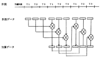
以上、1種類の負荷を繰り返しかけながら計測を行う負荷モードの生体光計測を説明したが、本発明の生体光計測装置は、このような負荷モードのみならず、例えば負荷のかけ方を異ならせながら或いは異なるタスクを与えながら計測を行う場合にも適用できる。そのような実施形態を図7に示す。この実施形態では、例えば負荷の大きさの異なる3種類のタスクT1、T2、T3をサイクリックに繰り返し、生体反応を観察する。
【0028】
この生体光計測においても、計測毎に生データをタイムコースとして表示する点及びタスク単位毎にpre、postをつなぐ近似直線或いは近似曲線と計測生データとの差からタスク単位毎のヘモグロビン濃度の相対変化を算出する点は上記実施形態と同様である。但し、この実施形態では、タスク単位の計測データの加算は、タスクの種類が同じもの同士で行う。即ち、3回のタスクT1、T2、T3負荷時の計測に引き続く、2順目以降の計測において、1回目のタスクT1負荷時の計測データと2回目のタスクT1負荷時の計測データを加算し、リアルタイムで表示する。
【0029】
また別の実施形態として、タスク単位毎のデータの加算を行わずに、負荷を次々と変化させて計測し、最適な負荷を見出したり、別のテストを行うことも可能である。
【0030】
【発明の効果】
本発明によれば、タスク負荷時における生体光計測に際し、リアルタイムで計測結果を観察することができるので、計測が適切か否かを瞬時に判断し、計測の継続や新たな条件設定を行うことができる。また本発明によれば、ノイズ発生の有無やノイズの特性をリアルタイムで把握できるので、それに応じてノイズが混入した計測データを除くことができ、正確な計測結果を得ることができる。
【図面の簡単な説明】
【図1】 本発明の生体光計測装置の全体概要を示す図
【図2】 本発明の生体光計測装置を用いた負荷モードの計測を説明する図
【図3】 本発明の生体光計測装置を用いた計測の一実施形態を示すフロー図
【図4】 記憶手段に格納される計測データの一例を示す図
【図5】 本発明の生体光計測装置の表示の一例を示す図
【図6】 処理手段における処理の状態を示す図
【図7】 本発明の生体光計測装置を用いた計測の他の実施形態を示す図
【符号の説明】
10・・・光源部
13・・・照射用光ファイバ
20・・・光計測部
21・・・検出用光ファイバ
30・・・信号処理部
31・・・記憶手段
32・・・処理手段
40・・・プローブ[0001]
[Technical field to which the invention belongs]
This invention irradiates a living body with light, detects light reflected on the surface of the living body, or passing through the vicinity of the surface, obtains biological information such as blood circulation, hemodynamics, hemoglobin change, etc. from the light quantity and images it. The present invention relates to a biological light measurement device, and more particularly to a biological light measurement device suitable for measurement in a relatively wide area.
[0002]
[Prior art]
The living body light measuring device irradiates the living body with wavelengths in the visible to infrared region, detects light reflected from the living body or light passing through the living body (hereinafter collectively referred to as transmitted light), and measures the inside of the living body. Therefore, biological information such as hemodynamics inside the living body can be obtained simply and non-invasively with low restraint on the subject. An apparatus capable of measuring a wide area by using a probe in which the tips of a plurality of optical fibers are arranged as a light irradiator and a light receiver is being applied in clinical practice (Japanese Patent Laid-Open No. 57-115232, Japanese Patent Laid-Open No. 57-115232). Sho-63-275323 etc.).
[0003]
As a measurement method using such a biological light measurement device, event mode measurement that detects sudden changes such as epileptic seizures by tracking changes in signals over time, and a predetermined load (task) ) Is repeatedly given, and there is a measurement method (hereinafter referred to as load mode or stimulus mode measurement) in which the active state of the brain at the time of task load is observed. The load mode measurement is described in, for example, Japanese Patent Application Laid-Open No. 9-98972. In this measurement, the biological light measurement is performed while repeatedly applying predetermined loads (tasks) such as light stimulation and exercise to the subject at regular intervals. From the obtained results, a relative change in the hemoglobin concentration at the time of task load (change with respect to no load) is obtained. At this time, a method of adding statistical data obtained by repetition to increase the statistical reliability is also employed (referred to as addition mode measurement).
[0004]
[Problems to be solved by the invention]
However, since the measurement of the amount of change in hemoglobin concentration in the conventional addition mode is performed after the measurement is completed, it is necessary to determine whether the measurement site is appropriate, whether the load is applied properly, and the number of repetitions is appropriate until the measurement is completed. I didn't. Therefore, after data analysis, for example, when it is found that the number of repetitions is not appropriate, the number of repetitions considered to be appropriate must be set again and measured again.
In addition, the subject may move during the measurement, and noise may be mixed in. However, since the noise is also reflected in the addition result, there is a possibility that the accuracy of the measurement is lowered.
[0005]
Therefore, the present invention can display a measurement result in real time for each measurement in one task unit in the biological light measurement in the addition mode, and thereby can perform measurement under appropriate conditions by one measurement. An object is to provide an apparatus. It is another object of the present invention to provide a biological light measurement device capable of preventing noise from being mixed into an addition result and performing highly accurate measurement.
[0006]
[Means for Solving the Problems]
The living body light measuring device of the present invention that achieves the above object includes a measuring probe that arranges a plurality of irradiation optical fibers and detecting optical fibers on the body surface of the living body, and the amount of light received by the detecting optical fiber for each measuring position. A biological light measurement apparatus comprising: an optical measurement means for detecting the information; and a signal processing means for calculating biological information of the subject based on a signal corresponding to the detected light quantity, and forming and displaying a biological information image. The signal processing means includes means for storing measurement data for each predetermined time unit (for example, a relative change in hemoglobin concentration) and means for displaying the measurement data for the time unit in real time during measurement. is there.
[0007]
According to such a biological light measurement device, the measurement result can be observed in real time at the time of the biological light measurement at the time of task load. Conditions can be set. In addition, according to the present invention, since the presence / absence of noise generation and the characteristics of noise can be grasped in real time, measurement data mixed with noise can be removed accordingly, and an accurate measurement result can be obtained.
[0008]
In the biological light measurement apparatus of the present invention, the signal processing means includes means for adding measurement data in units of time, and the display means displays the added measurement data in real time. In order to realize real-time display, the biological light measurement device of the present invention includes, for example, a clock that controls the time unit of measurement, and the signal processing means performs measurement for each time unit based on an operation signal from the clock. Data division, addition processing and display are time-division processing or parallel processing.
[0009]
Furthermore, in the biological light measurement device of the present invention, the signal processing means includes means for selecting time-unit measurement data to be removed from the addition target among the time-unit measurement data, and the addition means is selected by the selection means. The addition is performed using measurement data in units of time that have not been performed.
[0010]
According to this biological light measurement device, it is possible to display in real time a measurement result whose statistical significance has been enhanced by the addition process. Further, by eliminating data in a section in which noise is mixed in the addition process, a highly accurate measurement result can be obtained.
[0011]
DETAILED DESCRIPTION OF THE INVENTION
Hereinafter, embodiments of the biological light measurement device of the present invention will be described with reference to the drawings.
[0012]
FIG. 1 is a diagram showing an overall outline of the biological light measurement device of the present invention. This biological light measurement device mainly includes a light source unit 10 that irradiates a living body with near-infrared light, and light from the light source unit 10 that is transmitted through the living body or reflected or scattered from the living body (hereinafter collectively referred to as transmitted light).
[0013]
The light source unit 10 includes a semiconductor laser 11 that emits a plurality of wavelengths in a wavelength region from visible light to infrared, for example, 780 nm and 830 nm, and modulation for modulating these two wavelengths of light at a plurality of different frequencies. It comprises a plurality of
[0014]
The
[0015]
In the
[0016]
The
[0017]
In the biological light measurement apparatus having such a configuration, the biological optical measurement is performed by irradiating light modulated at different frequencies by the irradiation
[0018]
Next, the operation in the case of measuring the hemoglobin concentration in the load mode (stimulation mode) using the biological light measurement device will be described. FIG. 2 is a diagram showing an embodiment of the biological light measurement by the biological light measurement device of the present invention. In this measurement, first, a preliminary measurement is performed before the task load is performed, and then a certain section including the task load. The above measurement is repeated, and the relative change in the hemoglobin concentration in the section is measured. One section includes a time pre before loading a task, a task loading time task, a relaxation time relaxation after task loading, and a subsequent time post. Relaxation is the time required for the biological reaction due to the load to return to its original state. Here, pre, relaxation, and post are referred to as rests, and one task and the accompanying rest are measured as one task unit, and this is repeated a plurality of times. The start of each section and each time in the section are controlled so as to be constant in each repetition in accordance with a clock (not shown) provided in the apparatus.
[0019]
FIG. 3 shows the measurement procedure. As shown in the figure, first, preliminary measurement is performed before task loading (step 301), and the measurement state in a state where no task is loaded is checked (step 302). Next, measurement is performed in units of one task, and the relative change of the hemoglobin Hb in the section, that is, the change with respect to the reference data is measured (step 303). The task unit measurement is repeated a preset number of times (N).
[0020]
For each measurement, the raw data is displayed on the display unit of the input /
[0021]
FIG. 5 shows an example of a display displayed on the display unit. In the figure, (c) is a display of the time course of raw data (voltage data ). Here, measurement data of 24 channels are displayed in the time course for two types of measurement wavelengths (780 nm and 830 nm). This is displayed, for example, every measurement of 0.1S. The data between the two vertical lines is the data at task load. Further, (a) is an ID column for displaying the ID, name, and measurement date and time of the subject, and (b) shows the number and position of the measurement channel.
[0022]
On the other hand, the processing means 32 obtains an approximate straight line or approximate curve connecting pre and post of the task unit for the data of one task unit, and takes the difference between the approximate straight line or approximate curve and the data at the time of task load , to calculate the relative concentration of hemoglobin (step 306). Then, the calculated relative density is displayed on the display unit as shown in FIG. 5 (d) (step 309).
[0023]
Similarly, for the measurement of the second task unit, the measurement raw data is displayed on the display unit, and the relative concentration of hemoglobin is calculated by taking the difference from the approximate line or approximate curve connecting pre and post of the task unit. (Step 306). The processing means 32 further obtains an average value of the second data and the data measured before that (first data) and displays it on the display unit (steps 308 and 309). Thereafter, the processing from step 303 to step 309 is repeated until the set number of times N, and finally a graph of relative density, which is an average value of N times of task unit measurement, is obtained. Although FIG. 5 shows an example in which the relative density is displayed as a graph, the topography showing the relative density of each measurement point as a contour image on the measurement region is displayed instead of the graph display or together with the graph display. It is also possible.
[0024]
The series of processing from step 303 to step 309 uses the foreground of the processing means 32 and the background, which is its free time, as shown in FIG. 6, for example, by an operation signal from a clock that controls measurement in units of tasks. And done in real time. That is, for example, measurement is performed every 0.1 second and data is fetched (steps 303 to 305) in the foreground, and when the measurement for each task is completed, the background is started and the image for each task is calculated. Thereafter, the processing is performed in the background until the calculation of the image for each task and the display of the result are completed. At this time, the measurement display is processed as a high priority job after the measurement. Thus, an image can be displayed in real time in parallel with the measurement. Note that these processes can be performed in parallel by a plurality of processing means instead of time-sharing by the single processing means 32.
[0025]
As described above, according to the present embodiment, when performing biological measurement while repeatedly performing a task load, the average value of the measurement results of one task unit can be sequentially displayed in real time simultaneously with the measurement. Etc., it is possible to judge whether the measurement conditions (how to apply load and the number of repetitions of measurement) are appropriate during measurement. If necessary, change the conditions and continue or end the measurement. Is possible. In this case, as shown in the flow B and the subsequent steps in FIG. 3, for example, it is determined whether or not to continue further after the preset number of repetitions N (after step 310) (step 311). Via the
[0026]
Moreover, in the above-mentioned biological light measurement, since the generation of noise can be known in real time by observing the raw data displayed in the time course, the measurement data mixed with noise can be deleted from the subsequent processing. Is possible. Such determination can be made manually by looking at the measurement result displayed in real time, but can also be automatically determined by the processing means 32 . Such automatic determination is shown as
[0027]
As described above, the biological light measurement in the load mode in which the measurement is performed while repeatedly applying one kind of load has been described. However, the biological light measurement device of the present invention is not limited to such a load mode, for example, a method of applying the load is different. It can also be applied to measurement while giving different tasks. Such an embodiment is shown in FIG. In this embodiment, for example, three types of tasks T1, T2, and T3 having different loads are cyclically repeated to observe a biological reaction.
[0028]
Also in this biological light measurement, the relative value of the hemoglobin concentration for each task unit from the point of displaying the raw data as a time course for each measurement and the difference between the measured raw data and the approximate straight line or approximate curve connecting pre and post for each task unit The point of calculating the change is the same as in the above embodiment. However, in this embodiment, the addition of the measurement data for each task is performed between the same task types. That is, in the second and subsequent measurements following the measurement for the third task T1, T2, T3 load, the measurement data for the first task T1 load and the measurement data for the second task T1 load are added. Display in real time.
[0029]
As another embodiment, it is possible to measure by changing loads one after another without adding data for each task unit, and find an optimum load or perform another test.
[0030]
【The invention's effect】
According to the present invention, the measurement result can be observed in real time during the measurement of biological light at the time of task load. Therefore, it is possible to instantaneously determine whether the measurement is appropriate and to continue measurement or set new conditions. Can do. In addition, according to the present invention, since the presence / absence of noise generation and the characteristics of noise can be grasped in real time, measurement data mixed with noise can be removed accordingly, and an accurate measurement result can be obtained.
[Brief description of the drawings]
FIG. 1 is a diagram showing an overall outline of a biological light measurement device of the present invention. FIG. 2 is a diagram illustrating measurement of a load mode using the biological light measurement device of the present invention. FIG. 4 is a flowchart showing an example of measurement using a measurement device. FIG. 4 is a diagram showing an example of measurement data stored in a storage means. FIG. 5 is a diagram showing an example of display of the biological light measurement device of the present invention. FIG. 7 is a diagram showing the state of processing in the processing means. FIG. 7 is a diagram showing another embodiment of measurement using the biological light measuring device of the present invention.
10 ... Light source
13 ... Optical fiber for irradiation
20 ... Optical measurement unit
21 ... Optical fiber for detection
30 ... Signal processing section
31 ... Storage means
32 ... Processing means
40 ... Probe
Claims (3)
前記信号処理手段は、
所定のタスク毎に計測データを取得する計測を行い、前記計測毎に当該計測データを記憶する記憶手段と、
前記計測毎に、当該計測で取得した計測データの平均値を算出する計算手段と、
前記計算手段で算出した平均値を表示する表示手段と、
前記計測毎に取得した計測データのうち前記平均値算出対象から除去すべき計測データを選択する選択手段と、を備え、
前記選択手段は、前記計測データが予め定められた閾値を越えた時に当該計測データを前記除去すべき計測データとして選択し、
前記計算手段は、前記選択手段によって選択されなかったタスク単位の計測データを用いて前記平均値の算出を行うこと、
を特徴とする生体光計測装置。Corresponding to the detected light quantity, a measuring probe that arranges a plurality of optical fibers for irradiation and optical fibers for detection on the body surface of the living body, an optical measuring means that detects the amount of light received by the optical fiber for detection at each measurement position A biological light measurement device comprising signal processing means for calculating biological information of the subject based on a signal to be formed and forming and displaying a biological information image;
The signal processing means includes
A storage unit that performs measurement to acquire measurement data for each predetermined task, and stores the measurement data for each measurement ;
A calculation means for calculating an average value of measurement data acquired by the measurement for each measurement ,
Display means for displaying the average value calculated by the calculating means ;
Selecting means for selecting measurement data to be removed from the average value calculation target among the measurement data acquired for each measurement;
The selection means selects the measurement data as the measurement data to be removed when the measurement data exceeds a predetermined threshold value,
The calculating means calculates the average value using measurement data in units of tasks not selected by the selecting means ;
A biological light measuring device characterized by the above.
行われた前記計測の回数をカウントするカウント手段をさらに備え、
前記カウント手段は、前記選択手段によって計測データが選択された場合、当該計測データを取得した計測をカウントしないこと
を特徴とする生体光計測装置。 The biological light measurement device according to claim 1,
Further comprising a counting means for counting the number of measurements performed,
When the measurement data is selected by the selection means, the counting means does not count the measurement that acquired the measurement data.
A biological light measuring device characterized by the above .
前記計測は、複数の異なる条件で行われ、
前記計算手段は、同じ条件で行われた計測により取得された計測データ間で前記平均値を算出すること
を特徴とする生体光計測装置。 The biological light measurement device according to claim 1 or 2,
The measurement is performed under a plurality of different conditions,
The calculation means calculates the average value between measurement data acquired by measurement performed under the same conditions.
A biological light measuring device characterized by the above .
Priority Applications (1)
| Application Number | Priority Date | Filing Date | Title |
|---|---|---|---|
| JP2002036762A JP4071506B2 (en) | 2002-02-14 | 2002-02-14 | Biological light measurement device |
Applications Claiming Priority (1)
| Application Number | Priority Date | Filing Date | Title |
|---|---|---|---|
| JP2002036762A JP4071506B2 (en) | 2002-02-14 | 2002-02-14 | Biological light measurement device |
Publications (3)
| Publication Number | Publication Date |
|---|---|
| JP2003235849A JP2003235849A (en) | 2003-08-26 |
| JP2003235849A5 JP2003235849A5 (en) | 2005-06-23 |
| JP4071506B2 true JP4071506B2 (en) | 2008-04-02 |
Family
ID=27778558
Family Applications (1)
| Application Number | Title | Priority Date | Filing Date |
|---|---|---|---|
| JP2002036762A Expired - Fee Related JP4071506B2 (en) | 2002-02-14 | 2002-02-14 | Biological light measurement device |
Country Status (1)
| Country | Link |
|---|---|
| JP (1) | JP4071506B2 (en) |
Families Citing this family (4)
| Publication number | Priority date | Publication date | Assignee | Title |
|---|---|---|---|---|
| US8922781B2 (en) * | 2004-11-29 | 2014-12-30 | The General Hospital Corporation | Arrangements, devices, endoscopes, catheters and methods for performing optical imaging by simultaneously illuminating and detecting multiple points on a sample |
| EP2285271B1 (en) * | 2008-06-16 | 2011-09-07 | Koninklijke Philips Electronics N.V. | Monitoring a vital parameter of a patient with "in-situ" modulation scheme to avoid interference |
| JP5210733B2 (en) * | 2008-07-07 | 2013-06-12 | 株式会社日立メディコ | Biological light measuring device having stimulation presentation function and stimulation task presentation method |
| WO2015141423A1 (en) * | 2014-03-18 | 2015-09-24 | 株式会社 日立メディコ | Biophotonic measurement device and biophotonic measurement method |
-
2002
- 2002-02-14 JP JP2002036762A patent/JP4071506B2/en not_active Expired - Fee Related
Also Published As
| Publication number | Publication date |
|---|---|
| JP2003235849A (en) | 2003-08-26 |
Similar Documents
| Publication | Publication Date | Title |
|---|---|---|
| US10299710B2 (en) | Organism optical measurement device | |
| JP4097522B2 (en) | Biological light measurement device | |
| US6542763B1 (en) | Optical measurement equipment and recording medium and optical measurement method | |
| JP3916985B2 (en) | Biological light measurement device | |
| JP5324999B2 (en) | Biological light measurement device and biological light measurement method | |
| CN103732198A (en) | Rehabilitation device | |
| WO2003002004A1 (en) | Biological optical measuring instrument | |
| JP5248758B2 (en) | Optical measuring device | |
| JP2010119660A (en) | Organism measuring instrument | |
| US20050277817A1 (en) | Noninvasive measurement system for monitoring activity condition of living body | |
| JP4071506B2 (en) | Biological light measurement device | |
| JP4411208B2 (en) | Biological light measurement device | |
| JP2007196001A (en) | Optical measuring device for living body | |
| JP4428786B2 (en) | Biological light measurement device | |
| JP5210733B2 (en) | Biological light measuring device having stimulation presentation function and stimulation task presentation method | |
| JP2961608B1 (en) | Oxygen saturation measurement device | |
| JP2000300569A (en) | Biological light measuring instrument | |
| JP4230729B2 (en) | Biological light measurement device | |
| JP3952275B2 (en) | Biological light measurement device | |
| JP4272024B2 (en) | Optical biological measurement device | |
| US20220079504A1 (en) | Brain function measurement device | |
| JP4230726B2 (en) | Biological light measuring device and biological load reaction measuring device | |
| JP2010125147A (en) | Biometric instrument | |
| JP5195026B2 (en) | Light measuring device | |
| JP4946847B2 (en) | Optical brain functional imaging system |
Legal Events
| Date | Code | Title | Description |
|---|---|---|---|
| A521 | Written amendment |
Free format text: JAPANESE INTERMEDIATE CODE: A523 Effective date: 20041007 |
|
| A621 | Written request for application examination |
Free format text: JAPANESE INTERMEDIATE CODE: A621 Effective date: 20041007 |
|
| A131 | Notification of reasons for refusal |
Free format text: JAPANESE INTERMEDIATE CODE: A131 Effective date: 20071106 |
|
| A521 | Written amendment |
Free format text: JAPANESE INTERMEDIATE CODE: A523 Effective date: 20071213 |
|
| TRDD | Decision of grant or rejection written | ||
| A01 | Written decision to grant a patent or to grant a registration (utility model) |
Free format text: JAPANESE INTERMEDIATE CODE: A01 Effective date: 20080115 |
|
| A61 | First payment of annual fees (during grant procedure) |
Free format text: JAPANESE INTERMEDIATE CODE: A61 Effective date: 20080117 |
|
| R150 | Certificate of patent or registration of utility model |
Free format text: JAPANESE INTERMEDIATE CODE: R150 |
|
| FPAY | Renewal fee payment (event date is renewal date of database) |
Free format text: PAYMENT UNTIL: 20110125 Year of fee payment: 3 |
|
| FPAY | Renewal fee payment (event date is renewal date of database) |
Free format text: PAYMENT UNTIL: 20110125 Year of fee payment: 3 |
|
| FPAY | Renewal fee payment (event date is renewal date of database) |
Free format text: PAYMENT UNTIL: 20120125 Year of fee payment: 4 |
|
| FPAY | Renewal fee payment (event date is renewal date of database) |
Free format text: PAYMENT UNTIL: 20130125 Year of fee payment: 5 |
|
| FPAY | Renewal fee payment (event date is renewal date of database) |
Free format text: PAYMENT UNTIL: 20140125 Year of fee payment: 6 |
|
| LAPS | Cancellation because of no payment of annual fees |