JP4061609B2 - Image sensor having stretched pinned photodiode and method for manufacturing the same - Google Patents
Image sensor having stretched pinned photodiode and method for manufacturing the same Download PDFInfo
- Publication number
- JP4061609B2 JP4061609B2 JP18393599A JP18393599A JP4061609B2 JP 4061609 B2 JP4061609 B2 JP 4061609B2 JP 18393599 A JP18393599 A JP 18393599A JP 18393599 A JP18393599 A JP 18393599A JP 4061609 B2 JP4061609 B2 JP 4061609B2
- Authority
- JP
- Japan
- Prior art keywords
- conductivity type
- layer
- image sensor
- semiconductor layer
- type diffusion
- Prior art date
- Legal status (The legal status is an assumption and is not a legal conclusion. Google has not performed a legal analysis and makes no representation as to the accuracy of the status listed.)
- Expired - Fee Related
Links
- 238000004519 manufacturing process Methods 0.000 title claims description 26
- 238000000034 method Methods 0.000 title description 10
- 239000010410 layer Substances 0.000 claims description 196
- 238000009792 diffusion process Methods 0.000 claims description 81
- 239000004065 semiconductor Substances 0.000 claims description 46
- 239000011229 interlayer Substances 0.000 claims description 19
- 239000000758 substrate Substances 0.000 claims description 17
- 238000012546 transfer Methods 0.000 claims description 17
- 239000012535 impurity Substances 0.000 claims description 16
- XUIMIQQOPSSXEZ-UHFFFAOYSA-N Silicon Chemical compound [Si] XUIMIQQOPSSXEZ-UHFFFAOYSA-N 0.000 claims description 14
- 229910052710 silicon Inorganic materials 0.000 claims description 14
- 239000010703 silicon Substances 0.000 claims description 14
- 238000005468 ion implantation Methods 0.000 claims description 11
- 125000006850 spacer group Chemical group 0.000 claims description 8
- 238000002955 isolation Methods 0.000 claims description 3
- 238000000059 patterning Methods 0.000 claims 2
- BOTDANWDWHJENH-UHFFFAOYSA-N Tetraethyl orthosilicate Chemical compound CCO[Si](OCC)(OCC)OCC BOTDANWDWHJENH-UHFFFAOYSA-N 0.000 description 10
- OAICVXFJPJFONN-UHFFFAOYSA-N Phosphorus Chemical group [P] OAICVXFJPJFONN-UHFFFAOYSA-N 0.000 description 6
- 206010034972 Photosensitivity reaction Diseases 0.000 description 5
- 150000004767 nitrides Chemical class 0.000 description 5
- 230000036211 photosensitivity Effects 0.000 description 5
- 229910021420 polycrystalline silicon Inorganic materials 0.000 description 5
- 229920005591 polysilicon Polymers 0.000 description 5
- 230000010354 integration Effects 0.000 description 4
- 238000004518 low pressure chemical vapour deposition Methods 0.000 description 4
- RQNWIZPPADIBDY-UHFFFAOYSA-N arsenic atom Chemical group [As] RQNWIZPPADIBDY-UHFFFAOYSA-N 0.000 description 3
- ZOXJGFHDIHLPTG-UHFFFAOYSA-N Boron Chemical group [B] ZOXJGFHDIHLPTG-UHFFFAOYSA-N 0.000 description 2
- NBIIXXVUZAFLBC-UHFFFAOYSA-N Phosphoric acid Chemical compound OP(O)(O)=O NBIIXXVUZAFLBC-UHFFFAOYSA-N 0.000 description 2
- PNEYBMLMFCGWSK-UHFFFAOYSA-N aluminium oxide Inorganic materials [O-2].[O-2].[O-2].[Al+3].[Al+3] PNEYBMLMFCGWSK-UHFFFAOYSA-N 0.000 description 2
- 229910021417 amorphous silicon Inorganic materials 0.000 description 2
- 238000007796 conventional method Methods 0.000 description 2
- 238000013461 design Methods 0.000 description 2
- 238000010586 diagram Methods 0.000 description 2
- 230000000694 effects Effects 0.000 description 2
- 238000005530 etching Methods 0.000 description 2
- 230000003287 optical effect Effects 0.000 description 2
- 238000000206 photolithography Methods 0.000 description 2
- 229910021332 silicide Inorganic materials 0.000 description 2
- FVBUAEGBCNSCDD-UHFFFAOYSA-N silicide(4-) Chemical compound [Si-4] FVBUAEGBCNSCDD-UHFFFAOYSA-N 0.000 description 2
- 239000002002 slurry Substances 0.000 description 2
- 239000000126 substance Substances 0.000 description 2
- 229910021350 transition metal silicide Inorganic materials 0.000 description 2
- 229910000147 aluminium phosphate Inorganic materials 0.000 description 1
- YXTPWUNVHCYOSP-UHFFFAOYSA-N bis($l^{2}-silanylidene)molybdenum Chemical compound [Si]=[Mo]=[Si] YXTPWUNVHCYOSP-UHFFFAOYSA-N 0.000 description 1
- 230000000295 complement effect Effects 0.000 description 1
- 239000013078 crystal Substances 0.000 description 1
- 238000001514 detection method Methods 0.000 description 1
- -1 for example Inorganic materials 0.000 description 1
- 238000000227 grinding Methods 0.000 description 1
- 238000010438 heat treatment Methods 0.000 description 1
- 239000007943 implant Substances 0.000 description 1
- 150000002500 ions Chemical class 0.000 description 1
- 239000012528 membrane Substances 0.000 description 1
- 229910052751 metal Inorganic materials 0.000 description 1
- 239000002184 metal Substances 0.000 description 1
- 229910044991 metal oxide Inorganic materials 0.000 description 1
- 150000004706 metal oxides Chemical class 0.000 description 1
- 229910021344 molybdenum silicide Inorganic materials 0.000 description 1
- 239000012299 nitrogen atmosphere Substances 0.000 description 1
- 238000004806 packaging method and process Methods 0.000 description 1
- 229910052698 phosphorus Inorganic materials 0.000 description 1
- 239000011574 phosphorus Substances 0.000 description 1
- 238000001020 plasma etching Methods 0.000 description 1
- 238000005498 polishing Methods 0.000 description 1
- 238000012545 processing Methods 0.000 description 1
- 230000006798 recombination Effects 0.000 description 1
- 238000005215 recombination Methods 0.000 description 1
- 238000011160 research Methods 0.000 description 1
- 229910052715 tantalum Inorganic materials 0.000 description 1
- GUVRBAGPIYLISA-UHFFFAOYSA-N tantalum atom Chemical compound [Ta] GUVRBAGPIYLISA-UHFFFAOYSA-N 0.000 description 1
- 229910021341 titanium silicide Inorganic materials 0.000 description 1
- WQJQOUPTWCFRMM-UHFFFAOYSA-N tungsten disilicide Chemical compound [Si]#[W]#[Si] WQJQOUPTWCFRMM-UHFFFAOYSA-N 0.000 description 1
- 229910021342 tungsten silicide Inorganic materials 0.000 description 1
- 238000001039 wet etching Methods 0.000 description 1
Images


Classifications
-
- H—ELECTRICITY
- H01—ELECTRIC ELEMENTS
- H01L—SEMICONDUCTOR DEVICES NOT COVERED BY CLASS H10
- H01L27/00—Devices consisting of a plurality of semiconductor or other solid-state components formed in or on a common substrate
- H01L27/14—Devices consisting of a plurality of semiconductor or other solid-state components formed in or on a common substrate including semiconductor components sensitive to infrared radiation, light, electromagnetic radiation of shorter wavelength or corpuscular radiation and specially adapted either for the conversion of the energy of such radiation into electrical energy or for the control of electrical energy by such radiation
- H01L27/144—Devices controlled by radiation
- H01L27/146—Imager structures
- H01L27/14601—Structural or functional details thereof
- H01L27/14609—Pixel-elements with integrated switching, control, storage or amplification elements
-
- H—ELECTRICITY
- H01—ELECTRIC ELEMENTS
- H01L—SEMICONDUCTOR DEVICES NOT COVERED BY CLASS H10
- H01L27/00—Devices consisting of a plurality of semiconductor or other solid-state components formed in or on a common substrate
- H01L27/14—Devices consisting of a plurality of semiconductor or other solid-state components formed in or on a common substrate including semiconductor components sensitive to infrared radiation, light, electromagnetic radiation of shorter wavelength or corpuscular radiation and specially adapted either for the conversion of the energy of such radiation into electrical energy or for the control of electrical energy by such radiation
- H01L27/144—Devices controlled by radiation
- H01L27/146—Imager structures
- H01L27/14683—Processes or apparatus peculiar to the manufacture or treatment of these devices or parts thereof
- H01L27/14689—MOS based technologies
Description
【0001】
【発明が属する技術分野】
本発明はイメージセンサに関し、特に延伸されたピンドフォトダイオードを持つCMOS(Complementary Metal Oxide Semiconductor)イメージセンサ及びその製造方法に関する。
【0002】
【従来技術】
一般に、CMOSイメージセンサとは、CMOS製造技術を利用して光学的イメージを電気的信号に変換させる素子として、画素数ほどのMOSトランジスタを作ってこれを利用して順に出力を検出するスイッチング方式を採用している。現在、イメージセンサとして広く使われているCCD(Charge Coupled Device)イメージセンサに比べてCMOSイメージセンサは、駆動方式が簡便かつ多様なスキャニング方式の具現が可能で、信号処理回路を単一チップに集積でき製品の小型化が可能であるだけでなく、互換性のCMOS技術を使用するので製造単価を低くすることができ、電力消耗も非常に低いという長所があることは周知である。
【0003】
図1は従来技術に係るCMOSイメージセンサの単位画素の回路図である。
【0004】
図1に示された通り、CMOSイメージセンサの単位画素は、1個のピンドフォトダイオード(PPD)と4個のNMOSトランジスタで構成されている。4個のNMOSトランジスタはピンドフォトダイオード(PPD)で生成された光電荷をセンシングノードに伝達するためのトランスファートランジスタ(102)と、次の信号検出のためにセンシングノードをリセットするためのリセットトランジスタ(104)と、ソースフォロアの役割を遂行するためのドライブトランジスタ(106)と、アドレス信号に応答して出力端にデータを出力するためのセレクトトランジスタ(108)で構成される。ここで、電荷伝達効率が改善されるようにリセットトランジスタ(104)及びトランスファートランジスタ(102)はネイティブNMOSトランジスタで構成される。すなわち、負のしきい電圧を有するネイティブNMOSトランジスタは陽のしきい電圧による電圧降下により発生された電子損失を防止でき電荷伝達の効率を改善できる。
【0005】
図2は従来技術に係るCMOSイメージセンサの単位画素の断面図である。
【0006】
図2に示された通り、従来CMOSイメージセンサの単位画素はP+シリコン基板(201)、P型-エピ層(202)、P型-ウェル(203)、フィールド酸化膜(204)、ゲート酸化膜(205)、ゲート電極(206)、N-拡散領域(207)、P0拡散領域(208)、N+拡散領域(209)及び酸化膜スペーサ(210)を含む。
【0007】
ピンドフォトダイオード(PPD)は、P型-エピ層(202)とN-拡散領域(207)及びP0拡散領域(208)が積層されたPNP接合構造であり、このようなピンドフォトダイオードは電源電圧3.3V以下(例えば、1.2Vないし2.8V)で二つのP型領域が互いに等電位になるようにN-拡散領域(207)が安定的に完全空乏されている。
【0008】
また、トランスファーゲート(Tx)を持つトランスファートランジスタがネイティブトランジスタで構成されるために、トランスファーゲート(Tx)の下部でチャンネル役割をするP型-エピ層(202)にはトランジスタの特性(しきい電圧及びパンチスルー特性)を調節するためのイオン注入工程が省略できる。
【0009】
したがって、負のしきい電圧を有するNMOSトランジスタ(ネイティブトランジスタ)は電荷伝達効率を極大化でき、トランスファーゲート(Tx)とリセットゲート(Rx)間のP型-エピ層(202)の表面に形成されたN+拡散領域(センシングノード)はLDD領域なしで高濃度N+領域とみなされて運送される電荷量にともなうセンシングノードの電位量を増幅させるように構成されている。一方、P型-エピ層(202)がP+シリコン基板(201)に比べて基板ドーピング濃度が低いために、P型-エピ層(202)がピンドフォトダイオードの空乏層の深さを増加させて光感度を高めることができ、P+シリコン基板(201)の存在によって空乏層の下部の深い所で発生される光電荷が再結合され単位画素間のクロストーク(cross talk)効果を減らすことができるためである。
【0010】
従来のピンドフォトダイオードは、フィールド酸化膜(204)とトランスファーゲート(Tx)間のP型-エピ層(202)の一定領域に形成されるために、集積度を下げないでピンドフォトダイオードの単位面積を増大させることは不可能であった。また、従来のピンドフォトダイオードはデザインルールを超過する単位面積を増加させることができないために、CMOSイメージセンサのデザインルールが0.25μm以下となれば光感度が顕著に低下しイメージセンサの解像度が大きく落ちる短所があった。
【0011】
【発明が解決しようとする技術的課題】
本発明の目的は上記従来技術の問題点を解決するために案出されたものであり、集積度が維持された状態でフォトダイオードの単位画素当たりの面積の増加ひいては光感度を増加させることができるイメージセンサ及びその製造方法を提供することにある。
【0012】
【課題を解決するための手段】
上記目的を達成するために、本発明は、CMOSイメージセンサ製造方法であって、第1導電型の半導体層を準備する第1段階と、前記半導体層の全面上に層間絶縁膜を形成し、前記層間絶縁膜に、フォトダイオードが形成される領域の前記半導体層の一部を露出させるコンタクトホールを形成する第2段階と、前記コンタクトホールを埋め込んで前記半導体層に接触するように、前記層間絶縁膜上にエピタキシャル層を成長させる第3段階と、第2導電型の不純物を前記エピタキシャル層に注入して、前記エピタキシャル層を第 2 導電型拡散層にする第4段階と、第1導電型の不純物を前記第 2 導電型拡散層に注入して、前記第 2 導電型拡散層の厚さよりも薄い厚さで第 2 導電型拡散層の表面下に第 1 導電型拡散層を形成する第5段階と、前記第 2 導電型拡散層及び前記第 1 導電型拡散層をパターニングする第6段階とを含み、パターニングされた前記第 1 導電型拡散層の表面積が、前記半導体層及びパターニングされた前記第 2 導電型拡散層が前記コンタクトホールにおいて接する部分の面積より広く、PN接合が第 2 導電型拡散層及び前記第 1 導電型拡散層の界面に形成される。
【0013】
また、本発明は、第1導電型の半導体層を準備する第1段階と、前記半導体層の全面上に層間絶縁膜を形成し、前記層間絶縁膜に、フォトダイオードが形成される領域の前記半導体層の一部を露出させるコンタクトホールを形成する第2段階と、前記コンタクトホールの内壁面を含み、前記層間絶縁膜上を覆うように、且つ、前記半導体層に接触するようにエピタキシャル層を成長させる第3段階と、第2導電型の不純物を前記エピタキシャル層に注入して、前記エピタキシャル層を第 2 導電型拡散層にする第4段階と、前記層間絶縁膜上の前記第 2 導電型拡散層を除去して、前記第 2 導電型拡散層をシリンダー形状にパターニングする第5段階と、シリンダー形状の前記第 2 導電型拡散層を露出させるイオン注入マスクを形成する第6段階と、第1導電型の不純物をシリンダー形状の前記第 2 導電型拡散層に注入して、前記半導体層と直接的に接触し、前記シリンダー形状の肉厚よりも薄い厚さで前記第 2 導電型拡散層の表面下に第 1 導電形拡散層を形成する第7段階とを含み、前記第 1 導電型拡散層の表面積が、前記半導体層及びシリンダー形状の前記第 2 導電型拡散層が前記コンタクトホールにおいて接する部分の面積より広く、PN接合が前記第 2 導電型拡散層及び前記第 1 導電型拡散層の界面に形成される。
【0014】
また、本発明は、フォトダイオード及び前記フォトダイオードと電気的に接続された多数のモストランジスタを含むイメージセンサであって、多数の前記モストランジスタが形成された第1導電型の半導体層と、前記モストランジスタを含む前記半導体層の表面に形成され、前記フォトダイオードが形成される前記半導体層の表面を露出させるコンタクトホールが形成された絶縁層と、前記コンタクトホールを埋め込み、前記フォトダイオードが形成される領域の前記半導体層と接触し、前記絶縁層の上で水平に延伸する第2導電型の第1エピタキシャル層と、前記第1エピタキシャル層の表面下に形成された第1導電型の第2拡散領域とを備え、前記第 1 導電型の半導体層、前記第 2 導電型の第 1 エピタキシャル層、及び前記第 1 導電型の第 2 拡散領域が、積層されて、 PNP 接合構造のスタックト型ピンドフォトダイオードを構成する。
【0015】
また、本発明は、フォトダイオード及び前記フォトダイオードと電気的に接続された少なくとも一つのモストランジスタを含むイメージセンサであって、少なくとも前記一つのモストランジスタが形成された第1導電型の半導体層と、前記フォトダイオードが形成される領域の前記半導体層と接触し、前記半導体層と垂直に延伸するシリンダー形状の第2導電型の第1エピタキシャル層と、前記第1エピタキシャル層の表面下に形成された第1導電型の第2拡散領域とを備え、前記第 1 導電型の半導体層、前記第 2 導電型の第 1 エピタキシャル層、及び前記第 1 導電型の第 2 拡散領域が、積層されて、 PNP 接合構造のシリンダー型ピンドフォトダイオードを構成する。
【0016】
【発明の実施の形態】
以下、本発明の一実施形態を添付図面に基づき説明する。
【0017】
図3ないし図10は本発明の一実施形態に係るCMOSイメージセンサの単位画素の製造方法を説明するための断面図であり、シリンダー型ピンドフォトダイオードは所定の集積度のピンドフォトダイオードの単位面積を増加させて光感度を増加させる。
【0018】
図3に図示された通り、約10-100Ωcmの比抵抗を有するP型-エピ層(312)を具備したシリコン基板(311)上に約50-100KeV範囲のエネルギー及び7× 10 12 -9× 10 12 /cm2範囲のドーズ量条件でB(硼素)原子をイオン注入してP型-ウェル(313)を形成した後、公知の方法でその下部にチャンネルストップイオン注入領域を有する素子分離酸化膜(314)を形成し、上下部に各々マスク酸化膜(317)とゲート酸化膜(315)を有するゲート電極(316)を形成する。この時、ゲート電極(316)はポリシリコン膜で構成したりまたは転移金属シリサイド/ポリシリコンのポリサイド構造で構成でき、また金属シリサイド膜で構成できる。転移金属シリサイドには例えば、タングステンシリサイド、チタンシリサイド、タンタルシリサイド、モリブデンシリサイドなどが使用可能である。また、トランスファーゲート(Tx)及びリセットゲート(Rx)は約1μm以上のチャンネル寸法を持って、ドライブゲート(MD)及びセレクトゲート(Sx)は約0.5μm以下のチャンネル寸法を持つ。
【0019】
以後、図4に示された通り、P型-ウェル(313)領域の上部がオープンされるように第1マスクパターン(318)を形成し、約20-60KeV範囲のエネルギー及び1× 10 13 -5× 10 13 /cm2範囲のドーズ量条件でP(リン)原子をイオン注入してLDD(lightly dopeddrain)構造のための低濃度N-領域(319)を形成する。
【0020】
以後、図5に示された通り、第1マスクパターン(318)を除去した後、全体構造の上部に低圧化学気相蒸着法(LPCVD)で約2,000-2,500ÅのTEOS(Tetra-Ethyl-Ortho-Silicate)酸化膜を形成し、非等方性プラズマエッチングをすることで、露出されたゲート電極(316)の側壁に酸化膜スペーサ(320)を形成した後、ピンドフォトダイオードが形成される部分及びフィールド酸化膜(314)が覆われるように第2マスクパターン(321)を形成し、約50-90KeV範囲のエネルギー及び1× 10 15 -9× 10 15 /cm2範囲のドーズ量条件でAs(砒素)原子をイオン注入することによって、ソース/ドレーン領域の役割をするN+領域(322)を形成する。以後、約850-950℃、窒素雰囲気で約20-60分間熱処理する。これによりP型-ウェル(313)が形成されない部位のP型-エピ層(312)に注入されたAs(砒素)原子は他の不純物による拡散妨害を受けないために、相対的に拡散距離が増大してトランスファーゲート(Tx)及びリセットゲート(Rx)のゲート電極(316)の下部に十分に広がる。
【0021】
以後、図6に示された通り、第2マスクパターン(321)を除去した後、LPCVD方式で窒化膜(323)を約100-500Å厚さで形成し、窒化膜(323)の上部にTEOS酸化膜(324)を約8,000-10,000Å厚さで形成し、TEOS酸化膜(324)を化学的−機械的研磨(chemical mechanical polishing:CMP)技術で研磨するものであって、アルミナのようなスラリーを使用して約0.3〜0.5kg/cm2の研磨圧、約30〜40RPMの回転速度及び約3,000〜4,000Åの研磨厚さになるように条件を設定することによって、TEOS酸化膜(324)を平坦化させる。そして、フォトダイオードが形成される領域のP型-エピ層(312)を露出させるコンタクトホール(325)を写真エッチング法で形成する。この時、コンタクトホール(325)は窒化膜(323)によりP型-エピ層(312)の一部が覆われるように形成される。これは以後に最終的に形成されるピンドフォトダイオードのP0拡散領域がP型-エピ層(312)と電気的に十分に連結されて等電位を持つようにするためである。
【0022】
以後、図7に示された通り、基板の表面の段差によって約0.7-1.5μm程度の厚さを持つP型-エピ層(326)を、コンタクトホール (325) を含む基板表面の全面上に形成した後、約250-500KeV範囲のエネルギー及び1× 10 12 -3× 10 12 /cm2範囲のドーズ量条件でP(リン)原子を全面イオン注入して、N-拡散領域(327)を、コンタクトホール (325) 底面の P 型 - エピ層 (312) の表面下に形成する。
【0023】
N-拡散領域(327)を形成するためのP(リン)原子はP型-エピ層(326)に注入される。すなわち、露出されたP型-エピ層(326)にP(リン)イオンを注入して N 型のエピタキシャル層にする(以下、P型-エピ層(326)をN型-エピ層(326')という)。N型-エピ層(326')は多様なエピタキシャル成長方法で形成される。不純物濃度はエピタキシャル層の成長間に制御されることができ、P型-エピ層(312)で成長されるエピタキシャル層のためにN型不純物を提供できる。一方、コンタクトホール (325) 底面のP型-エピ層(312)上にもN型-エピ層(326')が存在するために、N-拡散領域(327)がコンタクトホール (325) 底面の P 型 - エピ層 (312) の表面下に深く形成される。特に、N型-エピ層(326')の"A"領域がP型-エピ層(312)と直接的に接触されていることを周知するべきである。
【0024】
以後、図8に示された通り、酸化膜(328)を開口部(200)に埋めたてした後に開口部(200)外の酸化膜(328)がエッチバックまたはCMPにより除去される。
【0025】
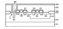
以後、図9に示された通り、TEOS酸化膜(324)の表面が露出されるようにTEOS酸化膜(324)上のN型-エピ層(326')をエッチバックして、シリンダー形状のN型-エピ層(326')のパターンを完成する。窒化膜(323)をエッチング停止層で使用してTEOS酸化膜(324)と開口部(200)に埋めたてされた酸化膜(328)とをHF溶液で湿式エッチングして除去し、窒化膜(323)を燐酸溶液で除去することで、コンタクトホール(325)の側壁及び底面にシリンダー形状にパターニングされたN型-エピ層(326')を残留させる。また、シリンダー形状にパターン形成されたN型-エピ層(326')が露出されるように第3マスクパターン(330)を形成し、N型-エピ層(326')の表面下に、約20-40KeV範囲のエネルギー及び3×10¹²-5×10¹²/cm2範囲のドーズ量条件で約5-10゜程度傾斜するようにBF2をイオン注入して、約0.1μm内外の接合深さを持つP0拡散領域(331)を形成する。この時、P0拡散領域(331)はチャンネルストップイオン注入領域近傍のP型-エピ層(312)の表面と直接的に接触されるために、ピンドフォトダイオードは低電圧で安定的に完全空乏が可能である。
【0026】
以後、図10に示された通り、第3マスクパターン(330)を除去して、 P0 拡散領域 (331) 、 N 型 - エピ層 (326') 、及び P 型 - エピ層 (312) が積層された PNP 接合構造で基板の上部に積層されたシリンダー型ピンドフォトダイオード(300)を完成する。シリンダー型ピンドフォトダイオード(300)は、光感知領域のP型-エピ層(312)と接触し、P型-エピ層(312)上で垂直方向に延伸する。
【0027】
図11ないし図16は本発明の他の実施例に係るCMOSイメージセンサの単位画素製造方法を説明するための断面図であり、スタックト型ピンドフォトダイオードは所定の集積度を有するピンドフォトダイオードの単位面積を増加させて光感度を増加させる。
【0028】
図11に示された通り、約15-25Ωcmの比抵抗を有するP型-エピ層(412)を具備したシリコン基板(411)上に約50-100KeV範囲のエネルギー及び7× 10 12 -9× 10 12 /cm2範囲のドーズ量条件でB(硼素)原子をイオン注入してP型-ウェル(413)を形成した後、公知の方法でフィールド酸化膜(414)を形成し、ゲート酸化膜(415)とドーピングされたポリシリコン膜で構成されたゲート電極(416)を形成する。この時、トランスファーゲート(Tx)及びリセットゲート(Rx)のチャンネル寸法は約1μm以上で、ドライブゲート(MD)及びセレクトゲート(Sx)のチャンネル寸法は約0.5μm以下である。
【0029】
以後、図12に示された通り、P型-ウェル(413)領域の上部が露出されるように第1マスクパターン(417)を形成し、約20-60KeV範囲のエネルギー及び1× 10 13 -5× 10 13 /cm2範囲のドーズ量条件でP(リン)原子をイオン注入してLDD構造のための低濃度N-領域(418)を形成する。
【0030】
以後、図13に示された通り、第1マスクパターン(417)を除去した後、全体構造の上部に低圧化学気相蒸着法で約2,000-2,500ÅのTEOS酸化膜(図示せず)を形成し、非等方性プラズマエッチングをすることで、露出されたゲート電極(416)の側壁に酸化膜スペーサ(419)を形成し、ピンドフォトダイオードが形成される部分及びフィールド酸化膜 (414)が覆われるように第2マスクパターン(420)を形成する。第2マスクパターン(420)及び酸化膜スペーサ(419)をイオン注入マスクで使用して約60-90KeV範囲のエネルギー及び1× 10 15 -9× 10 15 /cm2範囲のドーズ量条件でAs(砒素)原子をイオン注入することによって、ソース/ドレーン領域の役割をするN+拡散領域(421)を形成する。
【0031】
以後、図14に示された通り、第2マスクパターン(420)を除去した後、TEOS(Tetra-Ethyl-Ortho-Silicate)酸化膜のような平坦化用酸化膜(422)を約8,000-10,000Å厚さで形成し、平坦化用酸化膜(422)を化学的機械的研磨技術で研磨するものであり、アルミナのようなスラリーを使用して約0.3〜0.5kg/cm2の研磨圧、約30〜40RPMの回転速度及び約3,000〜4,000Åの研磨厚さになるように条件を設定することによって平坦化用酸化膜(422)を平坦化させる。
【0032】
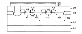
以後、図15に示された通り、フォトダイオードが形成される領域のP型-エピ層(412)を露出させるコンタクトホールを写真エッチング法で形成する。コンタクトホールを形成した後に、全体構造の上部に約0.5-1.5μm程度の厚さを持つP型-エピ層(427)を、コンタクトホールを含む基板表面の全面上に形成する。約250-500KeV範囲のエネルギー及び1× 10 12 -3× 10 12 /cm2範囲のドーズ(dose)量条件でP(リン)原子をイオン注入してP型-エピ層(427)内にN-拡散領域を形成してP 型 - エピ層 (427) を N 型のエピタキシャル層(以下、P型-エピ層(427)をN型-エピ層(427')という)にするので、P型-エピ層(412)の一部がN型-エピ層(427')と接触される。また、約20-40KeV範囲のエネルギー及び3× 10 12 -5× 10 12 /cm2範囲のドーズ量条件でBF2をイオン注入して、約0.1μm内外の接合深さを有するP0拡散領域(426)を、N型-エピ層(427')の表面下に形成する。
【0033】
この時、N型-エピ層(427')を形成する方法は次の通りである。すなわち、全体構造の上部にポリシリコン膜または非晶質シリコン膜を公知の方法で形成した後に、レーザーまたは棒型ヒーターのようなエネルギービームを上記ポリシリコン膜または非晶質シリコン膜に照射して上記シリコン膜を溶かし結晶化して数μmないしミリメートルグレーン寸法を有する単結晶エピタキシャルシリコン層に変形させて形成できる。
【0034】
以後、図16に示された通り、P0拡散領域(426)及びN型-エピ層(427')を写真エッチング法でパターニングして、P0拡散領域(426)、N型-エピ層(427')、及びP型-エピ層(412)が積層されたPNP接合構造を有するスタックト型ピンドフォトダイオードを完成する。スタックト型ピンドフォトダイオードは、コンタクトホール内で光感知領域のP型-エピ層(412)と接触し、酸化膜(422)上で水平方向に延伸する。
【0035】
本発明の技術思想は上記望ましい実施形態によって具体的に記述されたが、上記一実施形態はその説明のためのものでありその制限のためのものでないことを注意するべきである。
【0036】
また、本発明の技術分野の通常の専門家ならば本発明の技術思想の範囲内で多様な実施形態が可能さを理解することができることである。
【0037】
【発明の効果】
以上で説明した通り、本発明は延伸されたピンドフォトダイオードを形成してフォトダイオードの単位面積を増大させることで、CMOSイメージセンサの解像度を向上させることができる。
【図面の簡単な説明】
【図1】 従来技術に係るCMOSイメージセンサの単位画素の回路図。
【図2】 従来技術に係るCMOSイメージセンサの単位画素の断面図。
【図3】 本発明の一実施例に係るCMOSイメージセンサの単位画素の製造方法を説明するための断面図。
【図4】 同上
【図5】 同上
【図6】 同上
【図7】 同上
【図8】 同上
【図9】 同上
【図10】同上
【図11】 本発明の他の実施例に係るCMOSイメージセンサの単位画素の製造方法を説明するための断面図。
【図12】同上
【図13】同上
【図14】同上
【図15】同上
【図16】同上
【符号の説明】
311 P+シリコン基板
411 P+シリコン基板
312 P+シリコン基板
326 P+シリコン基板
412 P+シリコン基板
427 P型-エピ層
313 P型-エピ層
413 P型-ウェル
314 フィールド酸化膜
414 フィールド酸化膜
315 ゲート酸化膜
415 ゲート酸化膜
316 ゲート電極
416 ゲート電極
320 酸化膜スペーサ
419 酸化膜スペーサ
322 N+拡散領域
421 N+拡散領域
331 P0拡散領域
426 P0拡散領域
326' N型-エピタキシャル層
427' N型-エピタキシャル層[0001]
[Technical field to which the invention belongs]
The present invention relates to an image sensor, that in particular related to CMOS (Complementary Metal Oxide Semiconductor) image sensor and a manufacturing method thereof with stretched pinned photodiode.
[0002]
[Prior art]
In general, a CMOS image sensor is a device that uses CMOS manufacturing technology to convert an optical image into an electrical signal, and creates a MOS transistor of the number of pixels and uses it to detect the output sequentially. Adopted. Compared to the CCD (Charge Coupled Device) image sensor, which is currently widely used as an image sensor, the CMOS image sensor has a simple driving method and can implement various scanning methods. The signal processing circuit is integrated on a single chip. It is well known that not only the product can be miniaturized, but also has the advantages of using a compatible CMOS technology, which can reduce the unit cost of manufacture and also has a very low power consumption.
[0003]
FIG. 1 is a circuit diagram of a unit pixel of a CMOS image sensor according to the prior art.
[0004]
As shown in FIG. 1, the unit pixel of the CMOS image sensor is composed of one pinned photodiode (PPD) and four NMOS transistors. The four NMOS transistors are a transfer transistor (102) for transferring the photocharge generated by the pinned photodiode (PPD) to the sensing node, and a reset transistor (for resetting the sensing node for the next signal detection). 104), a drive transistor (106) for performing the role of a source follower, and a select transistor (108) for outputting data to the output terminal in response to an address signal. Here, the reset transistor (104) and the transfer transistor (102) are composed of native NMOS transistors so that the charge transfer efficiency is improved. That is, a native NMOS transistor having a negative threshold voltage can prevent an electron loss caused by a voltage drop due to a positive threshold voltage and can improve charge transfer efficiency.
[0005]
FIG. 2 is a cross-sectional view of a unit pixel of a conventional CMOS image sensor.
[0006]
As shown in FIG. 2, the unit pixel of the conventional CMOS image sensor is P + silicon substrate (201), P-type-epi layer (202), P-type-well (203), field oxide film (204), gate oxide film (205), a gate electrode (206), an N− diffusion region (207), a P0 diffusion region (208), an N + diffusion region (209), and an oxide film spacer (210).
[0007]
A pinned photodiode (PPD) is a PNP junction structure in which a P-type epi layer (202), an N-diffusion region (207), and a P0 diffusion region (208) are stacked. The N-diffusion region (207) is stably and completely depleted so that the two P-type regions are equipotential to each other at 3.3V or lower (for example, 1.2V to 2.8V).
[0008]
In addition, since the transfer transistor having the transfer gate (Tx) is composed of a native transistor, the P-type epi layer (202), which functions as a channel under the transfer gate (Tx), has transistor characteristics (threshold voltage). And an ion implantation step for adjusting punch-through characteristics) can be omitted.
[0009]
Therefore, the NMOS transistor (native transistor) having a negative threshold voltage can maximize the charge transfer efficiency and is formed on the surface of the P-type epi layer (202) between the transfer gate (Tx) and the reset gate (Rx). and N + diffusion region (sensing node) is configured to amplify the potential of the sensing node with the amount of charge transport is considered a high concentration N + realm without LDD regions. On the other hand, since the P-type epi layer (202) has a lower substrate doping concentration than the P + silicon substrate (201), the P type epi layer (202) increases the depth of the depletion layer of the pinned photodiode. it is possible to increase the photosensitivity, it is possible to reduce crosstalk (cross talk) effect between the lower and the photogenerating deep in the recombination is a unit pixel of the depletion layer by the presence of P + silicon substrate (201) Because.
[0010]
Since the conventional pinned photodiode is formed in a certain region of the P-type-epi layer (202) between the field oxide film (204) and the transfer gate (Tx), it is a unit of the pinned photodiode without reducing the degree of integration. It was impossible to increase the area. In addition, since the conventional pinned photodiode cannot increase the unit area exceeding the design rule, if the design rule of the CMOS image sensor is 0.25 μm or less, the photosensitivity is significantly reduced and the resolution of the image sensor is increased. There was a downside.
[0011]
[Technical Problem to be Solved by the Invention]
The object of the present invention has been devised to solve the above-mentioned problems of the prior art, and it is possible to increase the area per unit pixel of the photodiode and thus increase the photosensitivity while maintaining the degree of integration. An image sensor that can be used and a method for manufacturing the image sensor.
[0012]
[Means for Solving the Problems]
In order to achieve the above object , the present invention provides a CMOS image sensor manufacturing method , the first step of preparing a first conductivity type semiconductor layer, and forming an interlayer insulating film on the entire surface of the semiconductor layer, in the interlayer insulating film, a second step of forming a contact hole exposing a portion of the pre-Symbol semiconductor layer in a region where the photodiode is formed, said to be in contact with the semi-conductor layer by embedding the contact holes, a third step of growing an epitaxial layer on the interlayer insulating film, a fourth step of the second conductivity type impurity is implanted into the epitaxial layer to the epitaxial layer on the second conductive type diffusion layer, first by implanting first conductivity type impurities prior Symbol second conductivity type diffusion layer, the first conductivity type diffusion layer on the surface of a second conductivity type diffusion layer with a thickness smaller than the thickness of the second conductive type diffusion layer a fifth stage floors for forming the front Stories second conductivity type diffusion layer and And a sixth step of serial pattern over two packaging a first conductivity type diffusion layer, pattern over two ring surface area of said first conductivity type diffusion layer, the semi-conductor layer and patterned the second conductivity type wide diffusion layers Ri by surface product of the portion in contact in the contact hole, PN junction is made form the interface of the second conductive type diffusion layer and the first conductivity type diffusion layer.
[0013]
Further, the present invention provides a first step of preparing a first conductivity type semiconductor layer, and forming an interlayer insulating film on the entire surface of the semiconductor layer, and before the region where the photodiode is formed in the interlayer insulating film. a second step of forming a contact hole exposing a portion of the serial semiconductor layer includes an inner wall surface of the contact hole, so as to cover the interlayer insulating film above, and, epitaxial to contact the semi-conductor layer a third step of growing a layer, the second conductivity type impurity is implanted into the epitaxial layer, and a fourth step of the epitaxial layer to the second conductive type diffusion layer, wherein on the interlayer insulating film first by removing the second conductivity type diffusion layer, before Symbol a fifth step of pattern over two ring a second conductivity type diffusion layer on the cylindrical shape, the ion implantation mask to expose the second conductive type diffusion layer prior Symbol of cylindrical shape a sixth step you formed, of the first conductivity type not Net objects to be injected into the second conductive type diffusion layer prior Symbol of the cylinder shape, the semiconductor layer and in direct contact, the surface of the cylindrical shape of the thick second conductivity type diffusion layer with a thickness smaller than and a seventh step of forming a first conductivity type diffusion layer beneath, the surface area of the pre-Symbol first conductivity type diffusion layer, the semi-conductor layer and the second conductive type diffusion layer of the cylindrical shape is in said contact hole widely Ri by surface product of part in contact, PN junction is made form the interface of the prior SL second conductivity type diffusion layer and the first conductivity type diffusion layer.
[0014]
Further, the present invention is an image sensor including a photodiode and a large number of MOS transistors electrically connected to the photodiode, wherein the first conductivity type semiconductor layer in which the large number of MOS transistors are formed; An insulating layer formed on the surface of the semiconductor layer including the MOS transistor and exposing the surface of the semiconductor layer on which the photodiode is formed, and the photodiode is formed by embedding the contact hole. A first conductivity type first epitaxial layer that is in contact with the semiconductor layer in a region and extends horizontally on the insulating layer, and a first conductivity type second epitaxial layer formed below the surface of the first epitaxial layer. and a diffusion region, the first conductivity type semiconductor layer, the second conductive type first epitaxial layer, and a second diffusion region of the first conductivity type It is stacked, that make up a stacked-type pinned photodiode of the PNP junction structures.
[0015]
According to another aspect of the present invention, there is provided an image sensor including a photodiode and at least one MOS transistor electrically connected to the photodiode , wherein the first conductivity type semiconductor layer includes the at least one MOS transistor; A cylinder-shaped second conductivity type first epitaxial layer that is in contact with the semiconductor layer in a region where the photodiode is formed and extends perpendicularly to the semiconductor layer, and is formed below the surface of the first epitaxial layer. A first conductivity type second diffusion region, and the first conductivity type semiconductor layer, the second conductivity type first epitaxial layer, and the first conductivity type second diffusion region are laminated. , that make up a cylindrical pin photodiode of PNP junction structures.
[0016]
DETAILED DESCRIPTION OF THE INVENTION
Hereinafter, an embodiment of the present invention will be described with reference to the accompanying drawings.
[0017]
3 to 10 are cross-sectional views for explaining a method of manufacturing a unit pixel of a CMOS image sensor according to an embodiment of the present invention. A cylindrical pinned photodiode is a unit area of a pinned photodiode having a predetermined integration degree. To increase the photosensitivity.
[0018]
As illustrated in FIG. 3, energy in the range of about 50-100 KeV and 7 × 10 12 -9 × on a silicon substrate (311) with a P-type epi layer (312) having a specific resistance of about 10-100 Ωcm. 10 12 / cm 2 range of dough's weight condition with B (boron) atoms ion-implanted with P-type - after forming a well (313), elements having a channel stop implant region thereunder in a known manner An isolation oxide film (314) is formed, and a gate electrode (316) having a mask oxide film (317) and a gate oxide film (315) on the upper and lower portions is formed. At this time, the
[0019]
Thereafter, as shown in FIG. 4, the
[0020]
Thereafter, as shown in FIG. 5, after removing the first mask pattern (318), about 2,000-2,500mm TEOS (Tetra-Ethyl-Ortho) is formed on the entire structure by low pressure chemical vapor deposition (LPCVD). -Silicate) The portion where the pinned photodiode is formed after forming the oxide spacer (320) on the exposed side wall of the gate electrode (316) by forming the oxide film and performing anisotropic plasma etching and a field oxide film (314) is a second mask pattern (321) formed so as to be covered, about 50-90KeV range of energy and 1 × 10 15 -9 × 10 15 / cm 2 range of dough's volume conditions As a result of ion implantation of As (arsenic) atoms, an N + region (322) serving as a source / drain region is formed. Thereafter, heat treatment is performed at about 850-950 ° C. in a nitrogen atmosphere for about 20-60 minutes. As a result, the As (arsenic) atoms implanted in the P-type-epi layer (312) in the region where the P-type well (313) is not formed are not disturbed by diffusion by other impurities. It increases and spreads sufficiently under the gate electrode (316) of the transfer gate (Tx) and the reset gate (Rx).
[0021]
Thereafter, as shown in FIG. 6, after removing the second mask pattern (321), a nitride film (323) is formed to a thickness of about 100-500 mm by LPCVD, and TEOS is formed on the nitride film (323). oxide film (324) formed at about 8,000-10,000Å thick, chemically the TEOS oxide film (324) - mechanical Migaku Ken: be one which Migaku Ken in (chemical mechanical polishing CMP) technique, the alumina such slurries using about 0.3~0.5kg / cm2 of Ken Migaku圧, by setting condition so as to Ken MigakuAtsushi of rotational speed and about 3,000~4,000Å about 30~40RPM, TEOS oxide The membrane (324) is flattened. Then, P-type regions photo diodes are formed - to form epitaxial layer (312) contact holes (325) exposing the photographic etching method. At this time, the contact hole (325) is formed so that a part of the P-type epi layer (312) is covered with the nitride film (323). This P0 diffusion region of the pin photodiode which is finally formed later is P-type - is a order to you to have equipotential are electrically well connected to the epitaxial layer (312).
[0022]
Thereafter, as shown in FIG. 7, a P-type epi layer (326) having a thickness of about 0.7 to 1.5 μm is formed on the entire surface of the substrate including the contact hole (325) by a step on the surface of the substrate. after forming, the entire ion-implanting P (phosphorus) atoms dough's weight conditions of energy and 1 × 10 12 -3 × 10 12 / cm 2 range of about 250-500KeV range, N- diffusion region (327 ), and contact holes (325) the bottom surface of the P-type - is formed on the surface of a epilayer (312).
[0023]
P (phosphorus) atom to form a N- diffusion region (327) is P-type - are injected into the epitaxial layer (326). That dew out the P-type - epitaxial layer (3 26) to P (phosphorus) by implanting ions into the N-type epitaxial layer (hereinafter, P-type - epi layer (326) N-type - epitaxial layer ( 326 ')). The N-type epi layer (326 ′) is formed by various epitaxial growth methods. Impurity concentration can be controlled between the growth of the epitaxial layer, P-type - can provide N-type impurity for the epitaxial layer grown by the epitaxial layer (312). On the other hand, a contact hole (325) the bottom surface of the P-type - epitaxial layer (312) on the even N-type - for epi layer (326 ') exists, N- diffusion region (327) contact holes (325) of the bottom surface P-type - is deeply formed under the surface of the epitaxial layer (312). In particular, it should be noted that the “A” region of the N-type epi layer (326 ′) is in direct contact with the P-type epi layer (312).
[0024]
Thereafter, as shown in FIG. 8, after the oxide film (328) is filled in the opening (200), the oxide film (328) outside the opening (200) is removed by etch back or CMP.
[0025]
Thereafter, as shown in FIG. 9, the N-type epi layer (326 ′) on the TEOS oxide film (324) is etched back so that the surface of the TEOS oxide film (324) is exposed, and the cylinder-shaped Complete the pattern of the N-type epi layer (326 '). Using the nitride film (323) as an etching stop layer, the TEOS oxide film (324) and the oxide film (328) buried in the opening (200) are removed by wet etching with an HF solution, and the nitride film By removing (323) with a phosphoric acid solution, an N-type epi layer (326 ′) patterned in a cylinder shape remains on the side wall and bottom surface of the contact hole (325). In addition, a third mask pattern (330) is formed so that the N-type epi layer (326 ′) patterned in a cylinder shape is exposed. BF 2 is ion-implanted so that it is tilted by about 5-10 ° with an energy in the range of 20-40 KeV and a dose condition in the range of 3 × 10 12 -5 × 10 12 / cm 2. A P0 diffusion region (331) having a thickness is formed. At this time, since the P0 diffusion region (331) is in direct contact with the surface of the P-type epi layer (312) in the vicinity of the channel stop ion implantation region, the pinned photodiode is stably depleted stably at a low voltage. Is possible .
[0026]
Thereafter, as shown in FIG. 10, by removing the third mask pattern (330), P0 diffusion region (331), N-type - epitaxial layer (326 '), and P-type - epitaxial layer (312) laminated is cylindrical pinned photodiode (300) stacked on top of the substrate PNP junction structure to complete the. Cylindrical pinned photodiode (300), P-type optical sensing area - in contact with the epitaxial layer (312), P-type - stretched in the vertical direction on the epitaxial layer (312).
[0027]
11 to 16 are cross-sectional views for explaining a method of manufacturing a unit pixel of a CMOS image sensor according to another embodiment of the present invention. A stacked pinned photodiode is a unit of a pinned photodiode having a predetermined integration degree. Increase the photosensitivity by increasing the area.
[0028]
As shown in FIG. 11, an energy in the range of about 50-100 KeV and 7 × 10 12 -9 × on a silicon substrate (411) having a P-type epi layer (412) having a specific resistance of about 15-25 Ωcm. 10 12 / cm 2 range of dough's weight condition with B (boron) atoms ion-implanted with P-type - after forming a well (413), to form a field oxide film (414) in a known manner, the gate A gate electrode (416) composed of an oxide film (415) and a doped polysilicon film is formed. At this time, the channel size of the transfer gate (Tx) and the reset gate (Rx) is about 1 μm or more, and the channel size of the drive gate (MD) and the select gate (Sx) is about 0.5 μm or less.
[0029]
Thereafter, as shown in FIG. 12, the
[0030]
Thereafter, as shown in FIG. 13, after removing the first mask pattern (417), a TEOS oxide film (not shown) of about 2,000-2,500 mm is formed on the entire structure by low pressure chemical vapor deposition. and, by an anisotropic plasma etch, sidewall to form an oxide film spacer (419) of the exposed gate electrode (416), partial and field oxide pinned photodiode is formed (414) is A second mask pattern (420) is formed so as to be covered. In dough's weight conditions of energy and 1 × 10 15 -9 × 10 15 / cm 2 ranging from about 60-90KeV range using the second mask pattern (420) and the oxide film spacer (419) an ion implantation mask By ion-implanting As (arsenic) atoms, an N + diffusion region (421) serving as a source / drain region is formed.
[0031]
Thereafter, as shown in FIG. 14, after removing the second mask pattern (420), a planarization oxide film (422) such as a TEOS (Tetra-Ethyl-Ortho-Silicate) oxide film is formed at about 8,000-10,000. Å was formed at a thickness of, is intended to Migaku Ken planarization oxide film (422) by chemical mechanical Migaku Ken technology, research about 0.3~0.5kg / cm 2 using a slurry such as alumina grinding pressure, to planarize the planarization oxide film (422) by setting condition so as to Ken MigakuAtsushi of rotational speed and about 3,000~4,000Å about 30~40RPM.
[0032]
Thereafter, as shown in FIG. 15, a contact hole for exposing the P-type-epi layer (412) in the region where the photodiode is formed is formed by photolithography. After the contact hole is formed, a P-type epi layer (427) having a thickness of about 0.5 to 1.5 μm is formed on the entire surface of the substrate including the contact hole . About 250-500KeV range of energy and 1 × 10 12 -3 × 10 12 / cm 2 range of dose (dose) amount condition P (phosphorus) atoms ion-implanted with P-type - N epi layer (427) in - type P to form a diffusion region - epitaxial layer (427) the N-type epitaxial layer (or less, P-type - epitaxial layer (427) the N-type - epitaxial layer (referred to 427 ')) because it, P-type -A portion of the epi layer (412) is in contact with the N-type epi layer (427 '). Furthermore, the BF 2 in dough's weight conditions of energy and 3 × 10 12 -5 × 10 12 / cm 2 ranging from about 20-40KeV range by ion implantation, P0 spread with junction depth of about 0.1μm and out Region (426) is formed under the surface of the N-type epi layer (427 ').
[0033]
At this time, the method of forming the N-type epi layer (427 ′) is as follows. That is, after a polysilicon film or an amorphous silicon film is formed on the entire structure by a known method, the polysilicon film or the amorphous silicon film is irradiated with an energy beam such as a laser or a rod heater. The silicon film can be melted and crystallized to be transformed into a single crystal epitaxial silicon layer having a size of several μm to millimeter grains.
[0034]
Thereafter, as shown in FIG. 16, the P0 diffusion region (426) and the N- type epi layer (427 ′) are patterned by photolithography to form the P0 diffusion region (426), the N type epi layer (427 ′). And a stacked pinned photodiode having a PNP junction structure in which a P-type epi layer (412) is stacked. The stacked pinned photodiode is in contact with the P-type epi layer (412) in the light sensing region in the contact hole and extends in the horizontal direction on the oxide film (422).
[0035]
Although the technical idea of the present invention has been specifically described by the preferred embodiment, it should be noted that the above-described embodiment is for the purpose of illustration and not for the limitation.
[0036]
In addition, it is possible for a general expert in the technical field of the present invention to understand the possibility of various embodiments within the scope of the technical idea of the present invention.
[0037]
【The invention's effect】
As described above, the present invention can improve the resolution of the CMOS image sensor by forming a stretched pinned photodiode and increasing the unit area of the photodiode.
[Brief description of the drawings]
FIG. 1 is a circuit diagram of a unit pixel of a CMOS image sensor according to a conventional technique.
FIG. 2 is a cross-sectional view of a unit pixel of a CMOS image sensor according to a conventional technique.
FIG. 3 is a cross-sectional view for explaining a method for manufacturing a unit pixel of a CMOS image sensor according to an embodiment of the present invention.
[Fig. 4] Same as above [Fig. 5] Same as above [Fig. 6] Same as above [Fig. 7] Same as above [Fig. 8] Same as above [Fig. 9] Same as above [Fig. 10] Same as above [Fig. 11] CMOS image according to another embodiment of the present invention Sectional drawing for demonstrating the manufacturing method of the unit pixel of a sensor.
[Figure 12] Same as above [Figure 13] Same as above [Figure 14] Same as above [Figure 15] Same as above [Figure 16] Same as above [Description of symbols]
311 P + silicon substrate
411 P + silicon substrate
312 P + silicon substrate
326 P + silicon substrate
412 P + silicon substrate
427 P-type epi layer
313 P-epi layer
413 P-well
314 Field oxide film
414 Field oxide film
315 Gate oxide film
415 Gate oxide film
316 Gate electrode
416 Gate electrode
320 Oxide spacer
419 Oxide film spacer
322 N + diffusion region
421 N + diffusion region
331 P0 diffusion region
426 P0 diffusion region
326 'N-type epitaxial layer
427 'N-type epitaxial layer
Claims (24)
第1導電型の半導体層を準備する第1段階と、
前記半導体層の全面上に層間絶縁膜を形成し、前記層間絶縁膜に、フォトダイオードが形成される領域の前記半導体層の一部を露出させるコンタクトホールを形成する第2段階と、
前記コンタクトホールを埋め込んで前記半導体層に接触するように、前記層間絶縁膜上にエピタキシャル層を成長させる第3段階と、
第2導電型の不純物を前記エピタキシャル層に注入して、前記エピタキシャル層を第2導電型拡散層にする第4段階と、
第1導電型の不純物を前記第2導電型拡散層に注入して、前記第2導電型拡散層の厚さよりも薄い厚さで前記第2導電型拡散層の表面下に第1導電型拡散層を形成する第5段階と、
前記第2導電型拡散層及び前記第1導電型拡散層をパターニングしてスタックト型のフォトダイオードを形成する第6段階とを含み、
パターニングされた前記第1導電型拡散層の表面積が、前記半導体層及びパターニングされた前記第2導電型拡散層が前記コンタクトホールにおいて接する部分の面積より広く、
PN接合が第2導電型拡散層及び前記第1導電型拡散層の界面に形成されるCMOSイメージセンサ製造方法。A CMOS image sensor manufacturing method comprising:
A first stage of preparing a semiconductor layer of a first conductivity type;
Forming an interlayer insulating film on the entire surface of the semiconductor layer, and forming a contact hole in the interlayer insulating film to expose a part of the semiconductor layer in a region where a photodiode is formed;
A third step of growing an epitaxial layer on the interlayer insulating film so as to fill the contact hole and contact the semiconductor layer;
A fourth step of injecting a second conductivity type impurity into the epitaxial layer to make the epitaxial layer a second conductivity type diffusion layer;
Impurities of the first conductivity type are implanted into the second conductivity type diffusion layer, and the first conductivity type diffusion is formed below the surface of the second conductivity type diffusion layer with a thickness smaller than the thickness of the second conductivity type diffusion layer. A fifth stage of forming a layer;
A sixth step of patterning the second conductive type diffusion layer and the first conductive type diffusion layer to form a stacked type photodiode,
The surface area of the patterned first conductivity type diffusion layer is wider than the area of the portion where the semiconductor layer and the patterned second conductivity type diffusion layer are in contact with the contact hole,
A CMOS image sensor manufacturing method, wherein a PN junction is formed at an interface between a second conductive type diffusion layer and the first conductive type diffusion layer.
第1導電型の半導体層を準備する第1段階と、
前記半導体層の全面上に層間絶縁膜を形成し、前記層間絶縁膜に、フォトダイオードが形成される領域の前記半導体層の一部を露出させるコンタクトホールを形成する第2段階と、
前記コンタクトホールの内壁面を含み、前記層間絶縁膜上を覆うように、且つ、前記半導体層に接触するようにエピタキシャル層を成長させる第3段階と、
第2導電型の不純物を前記エピタキシャル層に注入して、前記エピタキシャル層を第2導電型拡散層にする第4段階と、
前記層間絶縁膜上の前記第2導電型拡散層を除去して、前記第2導電型拡散層をシリンダー形状にパターニングする第5段階と、
シリンダー形状の前記第2導電型拡散層を露出させるイオン注入マスクを形成する第6段階と、
第1導電型の不純物をシリンダー形状の前記第2導電型拡散層に注入して、前記半導体層と直接的に接触し、前記シリンダー形状の肉厚よりも薄い厚さで前記第2導電型拡散層の表面下に第1導電形拡散層を形成する第7段階とを含み、
前記第1導電型拡散層の表面積が、前記半導体層及びシリンダー形状の前記第2導電型拡散層が前記コンタクトホールにおいて接する部分の面積より広く、
PN接合が前記第2導電型拡散層及び前記第1導電型拡散層の界面に形成されるCMOSイメージセンサ製造方法。A CMOS image sensor manufacturing method comprising:
A first stage of preparing a semiconductor layer of a first conductivity type;
Forming an interlayer insulating film on the entire surface of the semiconductor layer, and forming a contact hole in the interlayer insulating film to expose a part of the semiconductor layer in a region where a photodiode is formed;
A third stage including an inner wall surface of the contact hole, covering the interlayer insulating film, and growing an epitaxial layer so as to contact the semiconductor layer;
A fourth step of injecting a second conductivity type impurity into the epitaxial layer to make the epitaxial layer a second conductivity type diffusion layer;
Removing the second conductivity type diffusion layer on the interlayer insulating film and patterning the second conductivity type diffusion layer into a cylinder shape; and
A sixth step of forming an ion implantation mask exposing the cylinder-shaped second conductivity type diffusion layer;
Impurities of the first conductivity type are injected into the cylinder-shaped second conductivity type diffusion layer, and are in direct contact with the semiconductor layer, and the second conductivity type diffusion is thinner than the thickness of the cylinder shape. Forming a first conductivity type diffusion layer below the surface of the layer, and
The surface area of the first conductivity type diffusion layer is wider than the area of the portion where the semiconductor layer and the cylindrical second conductivity type diffusion layer are in contact with the contact hole,
A CMOS image sensor manufacturing method, wherein a PN junction is formed at an interface between the second conductivity type diffusion layer and the first conductivity type diffusion layer.
前記第2導電型の不純物を、前記コンタクトホールの底面に成長した前記エピタキシャル層の下の前記半導体層にも注入する請求項6記載のCMOSイメージセンサ製造方法。In the fourth stage,
7. The method of manufacturing a CMOS image sensor according to claim 6, wherein the second conductivity type impurity is also implanted into the semiconductor layer under the epitaxial layer grown on the bottom surface of the contact hole.
前記層間絶縁膜の上の前記第2導電型拡散層をエッチバックし、前記第2導電型拡散層をシリンダー形状にパターニングする請求項6記載のCMOSイメージセンサ製造方法。In the fifth stage,
7. The method of manufacturing a CMOS image sensor according to claim 6, wherein the second conductivity type diffusion layer on the interlayer insulating film is etched back, and the second conductivity type diffusion layer is patterned into a cylinder shape.
多数の前記モストランジスタが形成された第1導電型の半導体層と、
前記モストランジスタを含む前記半導体層の表面に形成され、前記フォトダイオードが形成される前記半導体層の表面を露出させるコンタクトホールが形成された絶縁層と、
前記コンタクトホールを埋め込み、前記フォトダイオードが形成される領域の前記半導体層と接触し、前記絶縁層の上で水平に延伸する第2導電型の第1エピタキシャル層と、
前記第1エピタキシャル層の表面下に形成された第1導電型の第2拡散領域と、を備え、
前記第1導電型の半導体層、前記第2導電型の第1エピタキシャル層、及び前記第1導電型の第2拡散領域が、積層されて、PNP接合構造のスタックト型ピンドフォトダイオードを構成するイメージセンサ。An image sensor comprising a photodiode and a number of MOS transistors electrically connected to the photodiode,
A first conductive type semiconductor layer in which a plurality of MOS transistors are formed;
An insulating layer formed on a surface of the semiconductor layer including the MOS transistor and having a contact hole exposing the surface of the semiconductor layer on which the photodiode is formed;
A first conductivity type first epitaxial layer that fills the contact hole, contacts the semiconductor layer in a region where the photodiode is formed, and extends horizontally on the insulating layer;
A second diffusion region of the first conductivity type formed under the surface of the first epitaxial layer,
The first conductive type semiconductor layer, the second conductive type first epitaxial layer, and the first conductive type second diffusion region are stacked to form a stacked pinned photodiode having a PNP junction structure. Sensor.
少なくとも前記一つのモストランジスタが形成された第1導電型の半導体層と、
前記フォトダイオードが形成される領域の前記半導体層と接触し、前記半導体層と垂直に延伸するシリンダー形状の第2導電型の第1エピタキシャル層と、
前記第1エピタキシャル層の表面下に形成された第1導電型の第2拡散領域と、を備え、
前記第1導電型の半導体層、前記第2導電型の第1エピタキシャル層、及び前記第1導電型の第2拡散領域が、積層されて、PNP接合構造のシリンダー型ピンドフォトダイオードを構成するイメージセンサ。An image sensor comprising a photodiode and at least one MOS transistor electrically connected to the photodiode,
A semiconductor layer of a first conductivity type in which at least the one MOS transistor is formed;
A first epitaxial layer of a cylinder-shaped second conductivity type that is in contact with the semiconductor layer in a region where the photodiode is formed and extends perpendicular to the semiconductor layer;
A second diffusion region of the first conductivity type formed under the surface of the first epitaxial layer,
The first conductive type semiconductor layer, the second conductive type first epitaxial layer, and the first conductive type second diffusion region are stacked to form a cylindrical pinned photodiode having a PNP junction structure. Sensor.
前記トランスファーゲートが、前記半導体層との間にゲート絶縁膜を介して表面にマスク絶縁膜が形成され且つ側壁に絶縁膜スペーサが形成されたゲート電極を含む請求項18記載のイメージセンサ。The MOS transistor includes a transfer gate formed in close proximity to the photodiode;
19. The image sensor according to claim 18, wherein the transfer gate includes a gate electrode having a mask insulating film formed on a surface thereof and an insulating film spacer formed on a side wall through a gate insulating film between the transfer gate and the semiconductor layer.
Applications Claiming Priority (4)
| Application Number | Priority Date | Filing Date | Title |
|---|---|---|---|
| KR10-1998-0024712A KR100369344B1 (en) | 1998-06-29 | 1998-06-29 | Image sensor having pinned photodiode of cylinder type |
| KR1998-24712 | 1998-06-29 | ||
| KR1998-24650 | 1998-06-29 | ||
| KR1019980024650A KR100275125B1 (en) | 1998-06-29 | 1998-06-29 | Image sensor having stacked pinned photodiode |
Publications (2)
| Publication Number | Publication Date |
|---|---|
| JP2000031454A JP2000031454A (en) | 2000-01-28 |
| JP4061609B2 true JP4061609B2 (en) | 2008-03-19 |
Family
ID=26633827
Family Applications (1)
| Application Number | Title | Priority Date | Filing Date |
|---|---|---|---|
| JP18393599A Expired - Fee Related JP4061609B2 (en) | 1998-06-29 | 1999-06-29 | Image sensor having stretched pinned photodiode and method for manufacturing the same |
Country Status (3)
| Country | Link |
|---|---|
| US (1) | US6218210B1 (en) |
| JP (1) | JP4061609B2 (en) |
| TW (1) | TW424332B (en) |
Cited By (1)
| Publication number | Priority date | Publication date | Assignee | Title |
|---|---|---|---|---|
| KR20180128413A (en) | 2016-03-29 | 2018-12-03 | 신에쓰 가가꾸 고교 가부시끼가이샤 | Resin composition containing supported platinum catalyst, thermosetting organopolysiloxane composition using same, and curing method thereof |
Families Citing this family (12)
| Publication number | Priority date | Publication date | Assignee | Title |
|---|---|---|---|---|
| US6514785B1 (en) * | 2000-06-09 | 2003-02-04 | Taiwan Semiconductor Manufacturing Company | CMOS image sensor n-type pin-diode structure |
| FR2824665B1 (en) * | 2001-05-09 | 2004-07-23 | St Microelectronics Sa | CMOS TYPE PHOTODETECTOR |
| KR100462164B1 (en) * | 2002-01-11 | 2004-12-17 | 매그나칩 반도체 유한회사 | Cmos image sensor with enhanced fill factor |
| US7453129B2 (en) * | 2002-12-18 | 2008-11-18 | Noble Peak Vision Corp. | Image sensor comprising isolated germanium photodetectors integrated with a silicon substrate and silicon circuitry |
| KR100544957B1 (en) * | 2003-09-23 | 2006-01-24 | 동부아남반도체 주식회사 | Method for fabricating Complementary Metal Oxide Semiconductor image sensor |
| CN1879397A (en) * | 2003-10-13 | 2006-12-13 | 卓越设备技术公司 | Image sensor comprising isolated germanium photodetectors integrated with a silicon substrate and silicon circuitry |
| US7105906B1 (en) | 2003-11-19 | 2006-09-12 | National Semiconductor Corporation | Photodiode that reduces the effects of surface recombination sites |
| US7071019B2 (en) * | 2004-09-16 | 2006-07-04 | Taiwan Semiconductor Manufacturing Co., Ltd. | System and method to improve image sensor sensitivity |
| KR100769124B1 (en) * | 2005-12-28 | 2007-10-22 | 동부일렉트로닉스 주식회사 | CMOS image sensor and method for manufacturing the same |
| KR101517849B1 (en) * | 2008-08-28 | 2015-05-07 | 삼성전자주식회사 | Cmos image sensor having impurity filtering layer and method for manufacturing the same |
| US11424377B2 (en) | 2020-10-08 | 2022-08-23 | Globalfoundries U.S. Inc. | Photodiode with integrated, light focusing element |
| US11949034B2 (en) | 2022-06-24 | 2024-04-02 | Globalfoundries U.S. Inc. | Photodetector with dual doped semiconductor material |
Family Cites Families (6)
| Publication number | Priority date | Publication date | Assignee | Title |
|---|---|---|---|---|
| US4984047A (en) | 1988-03-21 | 1991-01-08 | Eastman Kodak Company | Solid-state image sensor |
| US5051797A (en) | 1989-09-05 | 1991-09-24 | Eastman Kodak Company | Charge-coupled device (CCD) imager and method of operation |
| US5625210A (en) * | 1995-04-13 | 1997-04-29 | Eastman Kodak Company | Active pixel sensor integrated with a pinned photodiode |
| US6026964A (en) * | 1997-08-25 | 2000-02-22 | International Business Machines Corporation | Active pixel sensor cell and method of using |
| US6023081A (en) * | 1997-11-14 | 2000-02-08 | Motorola, Inc. | Semiconductor image sensor |
| US6043115A (en) * | 1999-03-25 | 2000-03-28 | United Microelectronics Corp. | Method for avoiding interference in a CMOS sensor |
-
1999
- 1999-06-29 JP JP18393599A patent/JP4061609B2/en not_active Expired - Fee Related
- 1999-06-29 US US09/342,968 patent/US6218210B1/en not_active Expired - Lifetime
- 1999-07-01 TW TW088111195A patent/TW424332B/en not_active IP Right Cessation
Cited By (1)
| Publication number | Priority date | Publication date | Assignee | Title |
|---|---|---|---|---|
| KR20180128413A (en) | 2016-03-29 | 2018-12-03 | 신에쓰 가가꾸 고교 가부시끼가이샤 | Resin composition containing supported platinum catalyst, thermosetting organopolysiloxane composition using same, and curing method thereof |
Also Published As
| Publication number | Publication date |
|---|---|
| TW424332B (en) | 2001-03-01 |
| JP2000031454A (en) | 2000-01-28 |
| US6218210B1 (en) | 2001-04-17 |
Similar Documents
| Publication | Publication Date | Title |
|---|---|---|
| US7141836B1 (en) | Pixel sensor having doped isolation structure sidewall | |
| US6787386B2 (en) | Method of forming a photodiode for an image sensor | |
| US6921934B2 (en) | Double pinned photodiode for CMOS APS and method of formation | |
| US7524695B2 (en) | Image sensor and pixel having an optimized floating diffusion | |
| KR101485653B1 (en) | Cmos image sensors and method for forming the same | |
| US20040094784A1 (en) | Isolation process and structure for CMOS imagers | |
| US20070187734A1 (en) | A cmos imager photodiode with enhanced capacitance | |
| KR100959435B1 (en) | Image Sensor and Methof for Manufacturing Thereof | |
| US20060226428A1 (en) | Vertical gate device for an image sensor and method of forming the same | |
| KR20080083034A (en) | Image sensor with improved surface depletion | |
| KR20080084849A (en) | Method and apparatus for providing an integrated circuit having p and n doped gates | |
| JP4061609B2 (en) | Image sensor having stretched pinned photodiode and method for manufacturing the same | |
| US8124438B2 (en) | Method of fabricating CMOS image sensor | |
| CN101599499A (en) | The dot structure of non-image lag CMOS image sensor and manufacture method | |
| JP2004039832A (en) | Photoelectric converter and its manufacturing method | |
| US20090166687A1 (en) | Image Sensor and Method for Manufacturing the Same | |
| JP3884600B2 (en) | Photoelectric conversion device and manufacturing method thereof | |
| TW578303B (en) | Image sensor with pixel isolation region | |
| KR20070033718A (en) | CMOS image sensor and its manufacturing method | |
| KR20070029369A (en) | Method for fabrication of image sensor for preventing generation of dark current | |
| KR100731099B1 (en) | Cmos image sensor and method for manufacturing the same | |
| KR100369344B1 (en) | Image sensor having pinned photodiode of cylinder type | |
| KR100275125B1 (en) | Image sensor having stacked pinned photodiode | |
| US8227843B2 (en) | Image sensor and method for manufacturing thereof | |
| KR20040003961A (en) | Imase sensor and method for fabricating of the same |
Legal Events
| Date | Code | Title | Description |
|---|---|---|---|
| A977 | Report on retrieval |
Free format text: JAPANESE INTERMEDIATE CODE: A971007 Effective date: 20051206 |
|
| A711 | Notification of change in applicant |
Free format text: JAPANESE INTERMEDIATE CODE: A711 Effective date: 20060201 |
|
| A131 | Notification of reasons for refusal |
Free format text: JAPANESE INTERMEDIATE CODE: A131 Effective date: 20060517 |
|
| A521 | Request for written amendment filed |
Free format text: JAPANESE INTERMEDIATE CODE: A523 Effective date: 20060816 |
|
| RD03 | Notification of appointment of power of attorney |
Free format text: JAPANESE INTERMEDIATE CODE: A7423 Effective date: 20060816 |
|
| A131 | Notification of reasons for refusal |
Free format text: JAPANESE INTERMEDIATE CODE: A131 Effective date: 20061115 |
|
| A601 | Written request for extension of time |
Free format text: JAPANESE INTERMEDIATE CODE: A601 Effective date: 20070213 |
|
| A602 | Written permission of extension of time |
Free format text: JAPANESE INTERMEDIATE CODE: A602 Effective date: 20070216 |
|
| A521 | Request for written amendment filed |
Free format text: JAPANESE INTERMEDIATE CODE: A523 Effective date: 20070514 |
|
| A131 | Notification of reasons for refusal |
Free format text: JAPANESE INTERMEDIATE CODE: A131 Effective date: 20070718 |
|
| A521 | Request for written amendment filed |
Free format text: JAPANESE INTERMEDIATE CODE: A523 Effective date: 20071017 |
|
| TRDD | Decision of grant or rejection written | ||
| A01 | Written decision to grant a patent or to grant a registration (utility model) |
Free format text: JAPANESE INTERMEDIATE CODE: A01 Effective date: 20071114 |
|
| A61 | First payment of annual fees (during grant procedure) |
Free format text: JAPANESE INTERMEDIATE CODE: A61 Effective date: 20071214 |
|
| R150 | Certificate of patent or registration of utility model |
Free format text: JAPANESE INTERMEDIATE CODE: R150 |
|
| FPAY | Renewal fee payment (event date is renewal date of database) |
Free format text: PAYMENT UNTIL: 20110111 Year of fee payment: 3 |
|
| FPAY | Renewal fee payment (event date is renewal date of database) |
Free format text: PAYMENT UNTIL: 20110111 Year of fee payment: 3 |
|
| S111 | Request for change of ownership or part of ownership |
Free format text: JAPANESE INTERMEDIATE CODE: R313113 |
|
| FPAY | Renewal fee payment (event date is renewal date of database) |
Free format text: PAYMENT UNTIL: 20110111 Year of fee payment: 3 |
|
| R360 | Written notification for declining of transfer of rights |
Free format text: JAPANESE INTERMEDIATE CODE: R360 |
|
| FPAY | Renewal fee payment (event date is renewal date of database) |
Free format text: PAYMENT UNTIL: 20110111 Year of fee payment: 3 |
|
| R360 | Written notification for declining of transfer of rights |
Free format text: JAPANESE INTERMEDIATE CODE: R360 |
|
| R371 | Transfer withdrawn |
Free format text: JAPANESE INTERMEDIATE CODE: R371 |
|
| FPAY | Renewal fee payment (event date is renewal date of database) |
Free format text: PAYMENT UNTIL: 20110111 Year of fee payment: 3 |
|
| S633 | Written request for registration of reclamation of name |
Free format text: JAPANESE INTERMEDIATE CODE: R313633 |
|
| R371 | Transfer withdrawn |
Free format text: JAPANESE INTERMEDIATE CODE: R371 |
|
| FPAY | Renewal fee payment (event date is renewal date of database) |
Free format text: PAYMENT UNTIL: 20110111 Year of fee payment: 3 |
|
| S111 | Request for change of ownership or part of ownership |
Free format text: JAPANESE INTERMEDIATE CODE: R313113 |
|
| FPAY | Renewal fee payment (event date is renewal date of database) |
Free format text: PAYMENT UNTIL: 20110111 Year of fee payment: 3 |
|
| R350 | Written notification of registration of transfer |
Free format text: JAPANESE INTERMEDIATE CODE: R350 |
|
| FPAY | Renewal fee payment (event date is renewal date of database) |
Free format text: PAYMENT UNTIL: 20110111 Year of fee payment: 3 |
|
| FPAY | Renewal fee payment (event date is renewal date of database) |
Free format text: PAYMENT UNTIL: 20120111 Year of fee payment: 4 |
|
| FPAY | Renewal fee payment (event date is renewal date of database) |
Free format text: PAYMENT UNTIL: 20130111 Year of fee payment: 5 |
|
| R250 | Receipt of annual fees |
Free format text: JAPANESE INTERMEDIATE CODE: R250 |
|
| R250 | Receipt of annual fees |
Free format text: JAPANESE INTERMEDIATE CODE: R250 |
|
| R250 | Receipt of annual fees |
Free format text: JAPANESE INTERMEDIATE CODE: R250 |
|
| LAPS | Cancellation because of no payment of annual fees |