JP4059552B2 - Fatigue life test method and test apparatus for ferroelectric materials - Google Patents
Fatigue life test method and test apparatus for ferroelectric materials Download PDFInfo
- Publication number
- JP4059552B2 JP4059552B2 JP33884097A JP33884097A JP4059552B2 JP 4059552 B2 JP4059552 B2 JP 4059552B2 JP 33884097 A JP33884097 A JP 33884097A JP 33884097 A JP33884097 A JP 33884097A JP 4059552 B2 JP4059552 B2 JP 4059552B2
- Authority
- JP
- Japan
- Prior art keywords
- pulse
- polarization
- value
- inversions
- voltage
- Prior art date
- Legal status (The legal status is an assumption and is not a legal conclusion. Google has not performed a legal analysis and makes no representation as to the accuracy of the status listed.)
- Expired - Fee Related
Links
Images


Landscapes
- Testing Electric Properties And Detecting Electric Faults (AREA)
- Other Investigation Or Analysis Of Materials By Electrical Means (AREA)
- Investigating Or Analyzing Materials By The Use Of Electric Means (AREA)
- Testing Of Individual Semiconductor Devices (AREA)
- Measurement Of Resistance Or Impedance (AREA)
Description
【0001】
【発明の属する技術分野】
本発明は、不揮発性メモリ装置における強誘電体キャパシタ等に用いられる強誘電体材料の分極反転による疲労寿命を効率よく短時間で試験する方法、及びこの方法に基づいた試験装置に関する。
【0002】
【従来の技術】
不揮発性メモリ装置の強誘電体キャパシタにおいては、強誘電体の材料組成や電極構造を最適化するために、使用する強誘電体材料の分極反転の疲労寿命を試験することが重要である。一般に、強誘電体材料の分極反転寿命の試験は、強誘電体材料をはさむ電極の間に分極反転パルスを加えて行われる。
【0003】
強誘電体材料の疲労寿命試験の通常の方法を、図1と図2を参照して説明する。図1に示した試験装置において、1は試験しようとする強誘電体材料から作製された強誘電体キャパシタであり、2は電圧測定用コンデンサ、3は信号発生器、4はオッシロスコープである。試験に当たっては、信号発生器3(図1)より、図2に示したように印加電圧+V及び−VのN個の交互反転パルスを発生して強誘電体キャパシタ1(図1)の分極反転を行う。次に、+Vのパルスを2個(図2においてパルスA、B)、続いて−Vのパルスを2個(図2においてパルスC、D)、合計して4個のパルスを加える。このときに、これら4個のパルスについて電圧測定用コンデンサ2(図1)の両端の電圧(それぞれVA 、VB 、VC 、VD )をオッシロスコープ4(図1)で測定し、下式から残留分極値Qを求める。なお、下式中のCはコンデンサ2の容量である。
【0004】
【数6】

この分極反転試験を、強誘電体キャパシタに加える分極反転パルス数Nを徐々に増加させながら複数回行って残留分極値を測定し、この値が初期値(あるいは最高値)の20〜50%に劣化したときの反転回数を強誘電体材料の寿命とする。
【0006】
強誘電体キャパシタに用いられる強誘電体材料は、これまでPZT(Pb(Zr,Ti)O3 )などが主であり、残留分極値が初期値から20%劣化する反転疲労寿命は108 回程度であった。この場合、500kHzのパルスを加えてこの試験をすれば、200秒で結果が得られた。しかし、この程度の寿命ではメモリとして不十分であるため、近年、SBT(SrBi2 Ta2 O9 )などの反転疲労寿命の長い材料が開発されてきた。
【0007】
このSBTの反転疲労特性は、1010回の反転パルスを加えた後でもほとんど劣化しない。これは、500kHzのパルスを加えた場合、5時間以上の試験でも結果が得られないことを意味する。強誘電体キャパシタに用いる強誘電体の材料組成や電極構造の最適化のためには、疲労試験の結果をもとに次なる組成や構造を検討しなければならないので、疲労試験に大変な時間を要することになると、結果として開発時間の大幅な遅れを生じてしまう。
【0008】
【発明が解決しようとする課題】
本発明の目的は、反転疲労寿命が長い強誘電体材料であっても疲労寿命試験を短時間で行うのを可能にし、そして短時間の測定から疲労寿命を簡単に予測するのを可能にする試験方法及び試験装置を提供することである。また、強誘電体材料サンプルの寿命の合否を判定する試験方法と装置を提供することも、本発明の目的である。
【0009】
【課題を解決するための手段】
一つの側面において、本発明の強誘電体材料の疲労寿命試験方法は、強誘電体材料に分極反転パルスを加えて当該材料の残留分極値を測定することによりその材料の分極反転に伴う疲労特性を測定する疲労寿命試験方法であって、当該材料の残留分極値の減少率の関数を分極反転パルスの反転回数の関数として直線で回帰し、その直線を外挿して当該材料の疲労寿命を予測することを特徴とするものである。
【0010】
もう一つの側面において、本発明の強誘電体材料の疲労寿命試験方法は、強誘電体材料に分極反転パルスを加えて当該材料の残留分極を測定することによりその材料の分極反転に伴う疲労特性を測定する疲労寿命試験方法であって、
(1)分極反転する所定のパルス電圧における当該材料の残留分極値の減少率の関数を分極反転パルスの反転回数の関数として直線で回帰することにより得られる第一の回帰直線を得る操作を、パルス電圧の値を変えて複数回繰り返し、それによりパルス電圧に対応した複数の第一の回帰直線を求め、
(2)これらの複数の第一の回帰直線のそれぞれから、予め決められた残留分極値の減少率になるときの各パルス電圧Vでの反転回数NLを求め、
(3)得られたパルス電圧Vと反転回数NLとからなる複数のデータ対から、
【0011】
【数7】
なる第二の回帰直線を求め、
(4)この第二の回帰直線から、当該強誘電体材料の耐圧以下で且つ通常使用時の電圧より高い電圧Vtの分極反転パルスを加えたときに上記予め決められた残留分極値の減少率を与える反転回数NLtを求め、
(5)そして強誘電材料に対する以後の疲労試験を上記電圧Vtの分極反転パルスを使って行って、当該材料について残留分極値の減少率の関数を分極反転パルスの反転回数の関数として直線で回帰して得られた直線を外挿して疲労寿命を予測し、この予測寿命を与える反転回数NLt(s)を上記(4)で求めた反転回数NLtと比較することで、当該材料の疲労寿命試験の合否を判定することを特徴とする。
【0013】
本発明の強誘電体材料の一つの疲労寿命試験装置は、強誘電体材料に分極反転パルスを加えて当該材料の残留分極値を測定することによりその材料の分極反転に伴う疲労特性を測定する疲労寿命試験装置であって、強誘電体材料に分極反転パルスを加えて対応する残留分極値を測定する手段と、残留分極値の減少率の関数を分極反転パルスの反転回数の関数として直線で回帰し、その直線を外挿して、残留分極値の減少率が所定の値となるときの反転パルス回数を当該材料の疲労寿命として出力する手段を備えていることを特徴とする。
【0014】
本発明の強誘電体材料のもう一つの疲労寿命試験装置は、強誘電体材料に分極反転パルスを加えて当該材料の残留分極値を測定することによりその材料の分極反転に伴う疲労特性を測定する疲労寿命試験装置であって、
(a)強誘電体材料に分極反転パルスを加えて対応する残留分極値を測定する手段、及び
(b)(1)分極反転する所定のパルス電圧における当該材料の残留分極値の減少率の関数を分極反転パルスの反転回数の関数として直線で回帰することにより得られる第一の回帰直線を得る操作を、パルス電圧の値を変えて複数回繰り返し、それによりパルス電圧に対応した複数の第一の回帰直線を求め、次に(2)これらの複数の第一の回帰直線のそれぞれから、予め決められた残留分極値の減少率になるときの各パルス電圧Vの下での反転回数NLを求め、(3)得られたパルス電圧Vと反転回数NLとからなる複数のデータ対から、
【0015】
【数8】
なる第二の回帰直線を求め、(4)この第二の回帰直線から、当該強誘電体材料の耐圧以下で且つ通常使用時の電圧より高い電圧Vtの分極反転パルスを加えたときに上記予め決められた残留分極値の減少率を与える反転回数NLtを求め、そして(5)強誘電材料に対する以後の疲労試験を上記電圧Vtの分極反転パルスを使って行って、当該材料について残留分極値の減少率の関数を分極反転パルスの反転回数の関数として直線で回帰して得られた直線を外挿して疲労寿命を予測し、この予測寿命を与える反転回数NLt(s)を上記(4)で求めた反転回数NLtと比較することで、当該材料の疲労寿命試験の合否を判定し、そしてその結果を出力する手段、
を備えていることを特徴とする。
【0017】
【発明の実施の形態】
本発明における強誘電体材料サンプルの疲労試験では、その一部として、先に図1と図2を参照して説明した既知の疲労試験を利用することができる。すなわち、強誘電体材料を用いて形成されたキャパシタ1の電極間にN個の分極反転パルス電圧を加えた後、残留分極値Qを測定し、そしてこの測定を分極反転パルスの反転回数Nを徐々に増やしながら繰り返し行う。
【0018】
本発明では、次に、この測定結果を、横軸を反転回数Nの対数、縦軸を残留分極値Qの減少率の関数としてプロットして、図3に示すごとく直線で回帰する。一定の分極反転パルス電圧の下で、このように反転回数Nの対数と残留分極値Qの減少率の関数とが直線で回帰できることは、本発明以前には知られていなかったことである。
【0019】
ここで、残留分極値Qの減少率の関数として、基準正規分布のxなる確率を与える累積分布関数の逆関数
【0020】
【数9】
を用いる。ただし、
【0022】
【数10】
である。すなわち、横軸を logN、縦軸をKとしてプロットすることにより、これらは直線で回帰されることになる。
【0024】
本発明では、こうして得られた回帰直線を使って、強誘電体材料の分極反転寿命を予測することができる。その原理を、図4を参照して説明する。少ない反転回数Nのときの残留分極値Qを数点測定し、回帰直線を求めて、次にこれを外挿することで、多数の反転回数NのときのQを容易に予測できる。例えば、図4に示したように、残留分極値Qの減少率20%のときの寿命を、Qの減少率がそれよりはるかに少ないときのデータをもとに容易に予測することができる。従って、短時間の測定で容易に寿命を予測できる。
【0025】
図5は、従来の方法により、横軸をNの対数とし縦軸をQとしてプロットしたグラフであるが、パルス電圧Vを変えると異なる形状の曲線となるため、寿命の予測は容易でなく、正確な予測ができないことが分かる。
【0026】
次に、本発明のもう一つの方法を説明する。
分極反転パルス電圧を変えて疲労寿命試験を行うことにより、複数の分極反転パルスに対してそれぞれ上述の方法により回帰直線(第一の回帰直線)を求めて強誘電体材料の予測寿命を求め、図6に示すように各パルス電圧Vに対してそのときの予測寿命を与える反転回数NLの対数をプロットすると、
【0027】
【数11】
で表される第二の直線で回帰できることを発明者らは見いだした。ここで言う「予測寿命を与える反転回数」とは、残留分極値Qが初期値(または最大値)より所定の割合(例えば20%、あるいは20〜50%の間の任意の割合)だけ減少したときの反転回数Nの値である。
【0029】
この第二の回帰直線から、強誘電体材料の通常使用時の電圧における寿命と、それより高い電圧での寿命とを対応させることができる。強誘電体材料の寿命は電圧が高くなるに従って短くなる。従って、第二の回帰直線を使用し、また通常使用時の電圧より高い電圧で試験をすることにより、通常使用時の電圧における寿命試験と同等な試験を短時間で行うことができる。
【0030】
本発明の試験方法は、強誘電体材料に分極反転パルスを加えて対応する残留分極値を測定する手段と、上述の如く第一の回帰直線、第二の回帰直線を求めることができ、そして第一の回帰直線から予測される強誘電体材料の分極反転の予測疲労寿命、あるいは第二の回帰直線から強誘電体材料の寿命試験の合否判定結果を出力する手段を備えた試験装置で実施することが可能である。
【0031】
【実施例】
次に、実施例により本発明を更に説明するが、本発明がこれらの実施例に限定されないことは言うまでもない。
【0032】
〔実施例1〕
強誘電体材料をはさむ電極の間に分極反転パルスを加えて分極反転に伴う材料の疲労特性を測定する疲労寿命試験機(図1を参照して先に説明したように、強誘電体キャパシタと電圧測定用コンデンサを含む測定部と、分極反転信号発生器と、オッシロスコープとを含む)に、図7に例示した流れ図に従ってサンプル材料の予測疲労寿命を求めてそれを表示する機構を持つ手段(より具体的にはデータ処理のためのパーソナルコンピュータと表示装置)を備えつけた自動試験装置を使用する。
【0033】
この試験装置の測定部に配置した1個のキャパシタに対して、パルス数を10回、20回、40回、80回、……、と徐々に増加させて加えながら、残留分極値Qを測定する。残留分極値は、図5を参照すれば明らかなように、加えられる分極反転パルスの電圧により、必ずしも試験の初めから低下するとは限らない。そのため、本発明を実施する際には、残留分極値の変化が減少傾向に転じたことを確認するまで測定を行うことが重要である。得られた測定値が直前の測定値と比較して減少していれば、変化は減少傾向にあると考えられるが、測定誤差の可能性を排除するため、少なくとも3回の測定で連続して減少しているのを確認するのが好ましい。減少傾向の確認を更に確実にするためには、3回以上の連続した測定において残留分極値が減少し続け、且つその減少量が徐々に大きくなっていることを確認の基準とすることができる。この例では、図7の流れ図に見られるように、連続した4回の測定で残留分極値Qの減少が認められたた場合に、残留分極値が減少に転じたものと見なして測定を中止し、寿命の予測を行う。
【0034】
寿命予測のためには、まず、個々のキャパシタにおける残留分極値Qの最大値QMAX を基準にした減少率F(N)を下式
【0035】
【数12】
【0036】
次に、先に説明したようにして、累積分布関数の逆関数を用いて基準正規分布の累積確率がF(N)となるようなKを求める。すなわち、下式
【0037】
【数13】
を満たすKを求める。このとき、上式を計算するのでなく、公知の正規分布表を用いてもよい。そしてNとKの関係を、最小二乗法によって、
【0039】
【数14】
なる直線で回帰する。
【0041】
最後に、図4に示すごとく、予め入力されたQの許容範囲に対応した減少率Fを与えるKを求め(例えば図4においてQが最大値から20%減衰したときまでを許容する場合は、F=0.2、K=−0.842となる)、このKを与えるNを求める。このNが、本発明により予測された疲労寿命であり、この予測値が表示手段により表示される。
【0042】
〔実施例2〕
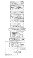
実施例1で使用した装置を、図8に例示した流れ図に従ってサンプル材料の寿命試験の合否を判定するように改造したものを使用する。
【0043】
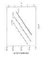
異なる3種のパルス電圧V1、V2、V3に対して、実施例1のごとくに寿命を予測する。ここでの測定においては、各電圧に対して同様の特性を持つと思われる別々のキャパシタを用いる。3種の電圧値は、予め入力された設定値でもよいし、例えばキャパシタを通常使用する電圧V1と、キャパシタの耐圧よりわずかに低い電圧V3と、両者の中間の電圧V2との3種の電圧を入力して再設定してもよい。(言うまでもなく、測定に使用するパルス電圧は4種以上としてもよい。)この測定により、図9に示したように、3種の電圧に対応して第一の回帰直線が三つ得られる。そしてこれらの回帰直線から、例えば残留分極値Qの減少率20%のときの、各電圧での予測寿命を与える反転回数NL1、NL2、NL3が求まる。
【0044】
次に、パルス電圧Vと予測寿命を与える反転回数NLとの関係を最小二乗法によって、
【0045】
【数15】
なる直線で回帰する(すなわち、図10に示した第二の回帰直線を求める)。そしてこの式を使って、通常使用時の電圧V1における予測寿命を与える反転回数NL1を、通常使用電圧V1より高くキャパシタの耐圧より低い任意の試験電圧Vtでの予測寿命を与える反転回数NLtに換算する(図10参照)。
【0047】
以後の他のサンプルにおける寿命測定では、サンプルにこの試験電圧Vtを加えて寿命試験を行い、実施例1のごとく寿命を予測して(図7の流れ図及び図4参照)、その寿命に対応する反転回数NLt(s)を求める。そしてこのNLt(s)を、先に前式を用いて換算された予測寿命を与える反転回数NLtと比較し、個々のサンプルの寿命についての合否を判断し、NLt(s)>NLtのとき合格とし、この結果を表示する。
【0048】
【発明の効果】
以上説明したように、本発明によれば、強誘電体材料の分極反転に伴う疲労寿命の試験を短時間で行え、また、短時間の測定から疲労寿命を容易に予測できる。そのため、不揮発性メモリ装置等で用いられる強誘電体材料について、材料組成や電極構造の最適化のための試験を効率よく行えることから、開発時間を大幅に短縮できる。
【図面の簡単な説明】
【図1】強誘電体材料の疲労寿命試験に用いられる装置を説明する図である。
【図2】強誘電体材料の残留分極値を求める方法を説明する図である。
【図3】本発明で得られる第一の回帰直線を説明する図である。
【図4】本発明の原理を説明する図である。
【図5】従来技術で得られる残留分極値と反転回数の対数との関係を示す曲線を例示する図である。
【図6】本発明で得られる第二の回帰直線を説明する図である。
【図7】実施例1で用いた装置において使用した流れ図である。
【図8】実施例2で用いた装置において使用した流れ図である。
【図9】実施例2で得られた、3種の電圧に対して得られた第一の回帰直線を示す図である。
【図10】実施例2で得られた第二の回帰直線を示す図である。
【符号の説明】
1…強誘電体キャパシタ
2…電圧測定用コンデンサ
3…信号発生器
4…オッシロスコープ[0001]
BACKGROUND OF THE INVENTION
The present invention relates to a method for efficiently and quickly testing a fatigue life due to polarization reversal of a ferroelectric material used for a ferroelectric capacitor or the like in a nonvolatile memory device, and a test apparatus based on this method.
[0002]
[Prior art]
In a ferroelectric capacitor of a nonvolatile memory device, it is important to test the fatigue life of polarization reversal of the ferroelectric material used in order to optimize the material composition and electrode structure of the ferroelectric. In general, the polarization inversion lifetime test of a ferroelectric material is performed by applying a polarization inversion pulse between electrodes sandwiching the ferroelectric material.
[0003]
A normal method for a fatigue life test of a ferroelectric material will be described with reference to FIGS. In the test apparatus shown in FIG. 1, 1 is a ferroelectric capacitor made of a ferroelectric material to be tested, 2 is a voltage measuring capacitor, 3 is a signal generator, and 4 is an oscilloscope. In the test, the signal generator 3 (FIG. 1) generates N alternating inversion pulses of applied voltages + V and −V as shown in FIG. 2 to invert the polarization of the ferroelectric capacitor 1 (FIG. 1). I do. Next, two pulses of + V (pulses A and B in FIG. 2), followed by two pulses of −V (pulses C and D in FIG. 2), a total of four pulses are added. At this time, as measured by these four of the voltage across (respectively V A, V B, V C , V D) of the
[0004]
[Formula 6]
This polarization inversion test is performed a plurality of times while gradually increasing the number N of polarization inversion pulses applied to the ferroelectric capacitor to measure the remanent polarization value, and this value is 20 to 50% of the initial value (or the maximum value). The number of inversions when deteriorated is defined as the lifetime of the ferroelectric material.
[0006]
Ferroelectric materials used for ferroelectric capacitors have so far been mainly PZT (Pb (Zr, Ti) O 3 ) and the like. The reversal fatigue life in which the remanent polarization value deteriorates by 20% from the initial value is 10 8 times. It was about. In this case, if this test was performed with a pulse of 500 kHz, the result was obtained in 200 seconds. However, since such a life is insufficient as a memory, a material having a long reversal fatigue life such as SBT (SrBi 2 Ta 2 O 9 ) has been developed in recent years.
[0007]
The inversion fatigue characteristics of this SBT hardly deteriorate even after 10 10 inversion pulses are applied. This means that when a pulse of 500 kHz is applied, no result is obtained even in a test of 5 hours or more. In order to optimize the material composition and electrode structure of a ferroelectric used in a ferroelectric capacitor, the following composition and structure must be examined based on the results of the fatigue test. As a result, the development time is greatly delayed.
[0008]
[Problems to be solved by the invention]
It is an object of the present invention to enable a fatigue life test to be performed in a short time even for a ferroelectric material having a long reversal fatigue life, and to easily predict the fatigue life from a short measurement. A test method and a test apparatus are provided. It is also an object of the present invention to provide a test method and apparatus for determining pass / fail of a ferroelectric material sample.
[0009]
[Means for Solving the Problems]
In one aspect, the fatigue life test method for a ferroelectric material according to the present invention includes a fatigue property associated with polarization inversion of a material by applying a polarization inversion pulse to the ferroelectric material and measuring a residual polarization value of the material. Is a fatigue life test method for measuring the regression rate of the remanent polarization value of the material as a function of the number of inversions of the polarization inversion pulse and extrapolating the line to predict the fatigue life of the material It is characterized by doing.
[0010]
In another aspect, the fatigue life test method for a ferroelectric material according to the present invention is a fatigue property associated with polarization reversal of a material by applying a polarization reversal pulse to the ferroelectric material and measuring the residual polarization of the material. A fatigue life test method for measuring
(1) An operation for obtaining a first regression line obtained by performing a linear regression using a function of the decrease rate of the remanent polarization value of the material at a predetermined pulse voltage for polarization inversion as a function of the number of inversions of the polarization inversion pulse, Change the value of the pulse voltage and repeat multiple times, thereby obtaining multiple first regression lines corresponding to the pulse voltage,
(2) From each of the plurality of first regression lines, obtain the number of inversions NL at each pulse voltage V when the rate of decrease of the remanent polarization value is determined in advance,
(3) From a plurality of data pairs consisting of the obtained pulse voltage V and the number of inversions NL,
[0011]
[Expression 7]
To obtain a second regression line
(4) From this second regression line, when the polarization reversal pulse having a voltage Vt that is lower than the breakdown voltage of the ferroelectric material and higher than the voltage during normal use is applied, the reduction rate of the predetermined remanent polarization value is increased. Find the number of inversions NLt that gives
(5) A subsequent fatigue test is performed on the ferroelectric material using the polarization reversal pulse of the voltage Vt, and a linear regression is performed with the function of the decrease rate of the remanent polarization value as a function of the number of times of reversal of the polarization reversal pulse. The fatigue life test of the material is performed by extrapolating the obtained straight line to predict the fatigue life and comparing the inversion number NLt (s) giving this predicted life with the inversion number NLt obtained in (4) above. It is characterized by determining pass / fail of this.
[0013]
One fatigue life test apparatus for a ferroelectric material according to the present invention measures a fatigue characteristic associated with polarization inversion of a material by applying a polarization inversion pulse to the ferroelectric material and measuring a residual polarization value of the material. This is a fatigue life test apparatus, in which a polarization reversal pulse is applied to a ferroelectric material and the corresponding remanent polarization value is measured, and a function of the decrease rate of the remanent polarization value as a function of the number of reversal times of the reversal polarization pulse. It is characterized in that there is provided means for regressing and extrapolating the straight line to output the number of inversion pulses when the rate of decrease of the remanent polarization value becomes a predetermined value as the fatigue life of the material.
[0014]
Another fatigue life test apparatus for ferroelectric materials according to the present invention measures the fatigue characteristics associated with the polarization inversion of a material by applying a polarization inversion pulse to the ferroelectric material and measuring the residual polarization value of the material. A fatigue life testing device,
(A) means for applying a polarization reversal pulse to a ferroelectric material and measuring the corresponding remanent polarization value; and (b) (1) a function of the decreasing rate of the remanent polarization value of the material at a predetermined pulse voltage for reversing the polarization. The operation of obtaining a first regression line obtained by performing a linear regression as a function of the number of inversions of the polarization inversion pulse is repeated a plurality of times while changing the value of the pulse voltage, whereby a plurality of first times corresponding to the pulse voltage are obtained. Next, (2) from each of the plurality of first regression lines, the number of inversions NL under each pulse voltage V when the rate of decrease of the remanent polarization value is determined in advance. (3) From a plurality of data pairs consisting of the obtained pulse voltage V and the number of inversions NL,
[0015]
[Equation 8]
(4) From this second regression line, when a polarization inversion pulse having a voltage Vt that is lower than the breakdown voltage of the ferroelectric material and higher than the voltage during normal use is applied, (5) A subsequent fatigue test on the ferroelectric material is performed using the polarization inversion pulse at the voltage Vt, and the residual polarization value of the material is determined. The fatigue life is predicted by extrapolating a straight line obtained by linear regression using the decrease rate function as a function of the number of inversions of the polarization inversion pulse, and the number of inversions NLt (s) giving this predicted life is expressed by the above (4). Means for determining the pass / fail of the fatigue life test of the material by comparing with the obtained inversion number NLt, and outputting the result;
It is characterized by having.
[0017]
DETAILED DESCRIPTION OF THE INVENTION
In the fatigue test of the ferroelectric material sample in the present invention, the known fatigue test described above with reference to FIGS. 1 and 2 can be used as a part thereof. That is, after applying N polarization inversion pulse voltages between the electrodes of the
[0018]
In the present invention, this measurement result is then regressed in a straight line as shown in FIG. 3 with the horizontal axis plotted as a logarithm of the number of inversions N and the vertical axis plotted as a function of the decreasing rate of the remanent polarization value Q. It was not known before the present invention that the logarithm of the number of inversions N and the function of the decreasing rate of the remanent polarization value Q can be linearly regressed under a constant polarization inversion pulse voltage.
[0019]
Here, as a function of the decreasing rate of the remanent polarization value Q, the inverse function of the cumulative distribution function giving the probability of x of the reference normal distribution
[Equation 9]
Is used. However,
[0022]
[Expression 10]
It is. That is, by plotting the horizontal axis as log N and the vertical axis as K, these are regressed in a straight line.
[0024]
In the present invention, the polarization inversion lifetime of the ferroelectric material can be predicted using the regression line thus obtained. The principle will be described with reference to FIG. By measuring several remanent polarization values Q at a small number of inversions N, obtaining a regression line, and then extrapolating this, the Q at a large number of inversions N can be easily predicted. For example, as shown in FIG. 4, the lifetime when the residual polarization value Q is reduced by 20% can be easily predicted based on data obtained when the Q reduction rate is much smaller. Therefore, the lifetime can be easily predicted by measuring in a short time.
[0025]
FIG. 5 is a graph in which the horizontal axis is the logarithm of N and the vertical axis is Q plotted according to the conventional method. However, since the curve has a different shape when the pulse voltage V is changed, the life prediction is not easy. It turns out that accurate prediction is impossible.
[0026]
Next, another method of the present invention will be described.
By performing the fatigue life test by changing the polarization inversion pulse voltage, the regression line (first regression line) is obtained for each of the plurality of polarization inversion pulses by the above-described method to obtain the predicted life of the ferroelectric material, As shown in FIG. 6, when the logarithm of the number of inversions NL giving the predicted lifetime at that time is plotted for each pulse voltage V,
[0027]
[Expression 11]
The inventors have found that the second straight line represented by can be regressed. Here, “the number of inversions that gives a predicted lifetime” means that the remanent polarization value Q is reduced by a predetermined rate (for example, 20%, or an arbitrary rate between 20 to 50%) from the initial value (or maximum value). This is the value of the number of inversions N.
[0029]
From this second regression line, the lifetime of the ferroelectric material at the normal use voltage can be made to correspond to the lifetime at a higher voltage. The lifetime of the ferroelectric material decreases as the voltage increases. Therefore, by using the second regression line and performing the test at a voltage higher than the voltage during normal use, a test equivalent to the life test at the voltage during normal use can be performed in a short time.
[0030]
The test method of the present invention can determine means for applying a polarization inversion pulse to a ferroelectric material and measuring the corresponding remanent polarization value, as described above, the first regression line, the second regression line, and Conducted with a test device equipped with means to output the predicted fatigue life of the polarization inversion of the ferroelectric material predicted from the first regression line or the pass / fail judgment result of the ferroelectric material life test from the second regression line Is possible.
[0031]
【Example】
EXAMPLES Next, although an Example demonstrates this invention further, it cannot be overemphasized that this invention is not limited to these Examples.
[0032]
[Example 1]
A fatigue life tester that measures the fatigue characteristics of a material accompanying polarization inversion by applying a polarization inversion pulse between electrodes sandwiching a ferroelectric material (as described above with reference to FIG. 1) Means including a measuring unit including a voltage measuring capacitor, a polarization inversion signal generator, and an oscilloscope) having a mechanism for obtaining and displaying the predicted fatigue life of the sample material in accordance with the flowchart illustrated in FIG. Specifically, an automatic test apparatus equipped with a personal computer and a display device for data processing is used.
[0033]
Residual polarization value Q is measured while gradually increasing the number of
[0034]
In order to predict the lifetime, first, a decrease rate F (N) based on the maximum value Q MAX of the remanent polarization value Q in each capacitor is expressed by the following equation:
[Expression 12]
[0036]
Next, as described above, K is obtained using the inverse function of the cumulative distribution function so that the cumulative probability of the reference normal distribution is F (N). That is, the following formula:
[Formula 13]
Find K that satisfies At this time, instead of calculating the above equation, a known normal distribution table may be used. And the relationship between N and K is calculated by the least squares method.
[0039]
[Expression 14]
It returns with the straight line.
[0041]
Finally, as shown in FIG. 4, K that gives a decrease rate F corresponding to a preliminarily inputted allowable range of Q is obtained (for example, when Q is attenuated by 20% from the maximum value in FIG. F = 0.2, K = −0.842), and N for giving this K is obtained. This N is the fatigue life predicted by the present invention, and this predicted value is displayed by the display means.
[0042]
[Example 2]
The apparatus used in Example 1 is modified so as to determine whether the life test of the sample material is acceptable or not according to the flowchart illustrated in FIG.
[0043]
For the three different types of pulse voltages V1, V2, and V3, the lifetime is predicted as in the first embodiment. In this measurement, separate capacitors that are considered to have similar characteristics for each voltage are used. The three kinds of voltage values may be set values inputted in advance, for example, three kinds of voltages: a voltage V1 that normally uses a capacitor, a voltage V3 that is slightly lower than the withstand voltage of the capacitor, and a voltage V2 that is intermediate between the two. You may reset by entering. (Of course, four or more pulse voltages may be used for measurement.) As shown in FIG. 9, three first regression lines are obtained corresponding to the three voltages. Then, from these regression lines, for example, the number of inversions NL1, NL2, and NL3 that gives the predicted life at each voltage when the rate of decrease of the residual polarization value Q is 20% can be obtained.
[0044]
Next, the relationship between the pulse voltage V and the number of inversions NL giving the predicted lifetime is determined by the least square method.
[0045]
[Expression 15]
(Ie, the second regression line shown in FIG. 10 is obtained). Using this equation, the number of inversions NL1 that gives the predicted life at the voltage V1 during normal use is converted into the number of inversions NLt that gives the expected life at any test voltage Vt that is higher than the normal use voltage V1 and lower than the withstand voltage of the capacitor. (See FIG. 10).
[0047]
In the life measurement of other samples thereafter, the test voltage Vt is applied to the sample, a life test is performed, and the life is predicted as in the first embodiment (see the flowchart in FIG. 7 and FIG. 4), and the life is measured. The number of inversions NLt (s) is obtained. Then, this NLt (s) is compared with the number of inversions NLt that gives the predicted life previously converted using the previous equation, and the pass / fail of each sample is judged. If NLt (s)> NLt, the test is passed. And display this result.
[0048]
【The invention's effect】
As described above, according to the present invention, the fatigue life test accompanying the polarization reversal of the ferroelectric material can be performed in a short time, and the fatigue life can be easily predicted from the short time measurement. For this reason, the ferroelectric material used in the nonvolatile memory device or the like can be efficiently tested for optimization of the material composition and electrode structure, so that the development time can be greatly shortened.
[Brief description of the drawings]
FIG. 1 is a diagram for explaining an apparatus used for a fatigue life test of a ferroelectric material.
FIG. 2 is a diagram illustrating a method for obtaining a remanent polarization value of a ferroelectric material.
FIG. 3 is a diagram illustrating a first regression line obtained by the present invention.
FIG. 4 is a diagram illustrating the principle of the present invention.
FIG. 5 is a diagram illustrating a curve indicating a relationship between a remanent polarization value obtained by a conventional technique and a logarithm of the number of inversions.
FIG. 6 is a diagram illustrating a second regression line obtained by the present invention.
7 is a flowchart used in the apparatus used in Example 1. FIG.
FIG. 8 is a flowchart used in the apparatus used in Example 2;
9 is a diagram showing first regression lines obtained with respect to three types of voltages obtained in Example 2. FIG.
10 is a diagram showing a second regression line obtained in Example 2. FIG.
[Explanation of symbols]
DESCRIPTION OF
Claims (9)
(1)分極反転する所定のパルス電圧における当該材料の残留分極値の減少率の関数を分極反転パルスの反転回数の関数として直線で回帰することにより得られる第一の回帰直線を得る操作を、パルス電圧の値を変えて複数回繰り返し、それによりパルス電圧に対応した複数の第一の回帰直線を求め、
(2)これらの複数の第一の回帰直線のそれぞれから、予め決められた残留分極値の減少率になるときの各パルス電圧Vでの反転回数NLを求め、
(3)得られたパルス電圧Vと反転回数NLとからなる複数のデータ対から、
(4)この第二の回帰直線から、当該強誘電体材料の耐圧以下で且つ通常使用時の電圧より高い電圧Vtの分極反転パルスを加えたときに上記予め決められた残留分極値の減少率を与える反転回数NLtを求め、
(5)そして強誘電材料に対する以後の疲労試験を上記電圧Vtの分極反転パルスを使って行って、当該材料について残留分極値の減少率の関数を分極反転パルスの反転回数の関数として直線で回帰して得られた直線を外挿して疲労寿命を予測し、この予測寿命を与える反転回数NLt(s)を上記(4)で求めた反転回数NLtと比較することで、当該材料の疲労寿命試験の合否を判定することを特徴とする強誘電材料の疲労寿命試験方法。A fatigue life test method for measuring fatigue characteristics associated with polarization reversal of a material by applying a polarization reversal pulse to a ferroelectric material and measuring a residual polarization value of the material,
(1) An operation for obtaining a first regression line obtained by performing a linear regression using a function of the decrease rate of the remanent polarization value of the material at a predetermined pulse voltage for polarization inversion as a function of the number of inversions of the polarization inversion pulse, Change the value of the pulse voltage and repeat multiple times, thereby obtaining multiple first regression lines corresponding to the pulse voltage,
(2) From each of the plurality of first regression lines, obtain the number of inversions NL at each pulse voltage V when the rate of decrease of the remanent polarization value is determined in advance,
(3) From a plurality of data pairs consisting of the obtained pulse voltage V and the number of inversions NL,
(4) From this second regression line, when the polarization reversal pulse having a voltage Vt that is lower than the breakdown voltage of the ferroelectric material and higher than the voltage during normal use is applied, the reduction rate of the predetermined remanent polarization value is increased. Find the number of inversions NLt that gives
(5) A subsequent fatigue test on the ferroelectric material is performed using the polarization inversion pulse at the voltage Vt, and a linear regression is performed with the function of the decrease rate of the remanent polarization value as a function of the number of inversions of the polarization inversion pulse. The fatigue life test of the material is performed by extrapolating the obtained straight line to predict the fatigue life and comparing the inversion number NLt (s) giving this predicted life with the inversion number NLt obtained in (4) above. A method for testing a fatigue life of a ferroelectric material, characterized in that pass / fail is determined.
(a)強誘電体材料に分極反転パルスを加えて対応する残留分極値を測定する手段、及び
(b)(1)分極反転する所定のパルス電圧における当該材料の残留分極値の減少率の関数を分極反転パルスの反転回数の関数として直線で回帰することにより得られる第一の回帰直線を得る操作を、パルス電圧の値を変えて複数回繰り返し、それによりパルス電圧に対応した複数の第一の回帰直線を求め、次に(2)これらの複数の第一の回帰直線のそれぞれから、予め決められた残留分極値の減少率になるときの各パルス電圧Vの下での反転回数NLを求め、(3)得られたパルス電圧Vと反転回数NLとからなる複数のデータ対から、
を備えていることを特徴とする強誘電体材料の疲労寿命試験装置。A fatigue life test apparatus for measuring fatigue characteristics associated with polarization reversal of a material by applying a polarization reversal pulse to a ferroelectric material and measuring a remanent polarization value of the material,
(A) means for applying a polarization reversal pulse to a ferroelectric material and measuring the corresponding remanent polarization value; and (b) (1) a function of the decreasing rate of the remanent polarization value of the material at a predetermined pulse voltage for reversing the polarization. The operation of obtaining a first regression line obtained by performing a linear regression as a function of the number of inversions of the polarization inversion pulse is repeated a plurality of times while changing the value of the pulse voltage, whereby a plurality of first times corresponding to the pulse voltage are obtained. Next, (2) from each of the plurality of first regression lines, the number of inversions NL under each pulse voltage V when the rate of decrease of the remanent polarization value is determined in advance. (3) From a plurality of data pairs consisting of the obtained pulse voltage V and the number of inversions NL,
A fatigue life test apparatus for a ferroelectric material, comprising:
Priority Applications (1)
| Application Number | Priority Date | Filing Date | Title |
|---|---|---|---|
| JP33884097A JP4059552B2 (en) | 1997-12-09 | 1997-12-09 | Fatigue life test method and test apparatus for ferroelectric materials |
Applications Claiming Priority (1)
| Application Number | Priority Date | Filing Date | Title |
|---|---|---|---|
| JP33884097A JP4059552B2 (en) | 1997-12-09 | 1997-12-09 | Fatigue life test method and test apparatus for ferroelectric materials |
Publications (2)
| Publication Number | Publication Date |
|---|---|
| JPH11174026A JPH11174026A (en) | 1999-07-02 |
| JP4059552B2 true JP4059552B2 (en) | 2008-03-12 |
Family
ID=18321927
Family Applications (1)
| Application Number | Title | Priority Date | Filing Date |
|---|---|---|---|
| JP33884097A Expired - Fee Related JP4059552B2 (en) | 1997-12-09 | 1997-12-09 | Fatigue life test method and test apparatus for ferroelectric materials |
Country Status (1)
| Country | Link |
|---|---|
| JP (1) | JP4059552B2 (en) |
Families Citing this family (3)
| Publication number | Priority date | Publication date | Assignee | Title |
|---|---|---|---|---|
| EP1394811A1 (en) | 2002-08-28 | 2004-03-03 | Matsushita Electric Industrial Co., Ltd. | Accelerated test method for ferroelectric memory device |
| JP2013074461A (en) * | 2011-09-28 | 2013-04-22 | Casio Comput Co Ltd | Image processor, image processing method and program |
| CN107102057B (en) * | 2017-04-28 | 2020-03-10 | 西南大学 | Magnetic field-based cable-stayed bridge cable fatigue damage monitoring system and method |
-
1997
- 1997-12-09 JP JP33884097A patent/JP4059552B2/en not_active Expired - Fee Related
Also Published As
| Publication number | Publication date |
|---|---|
| JPH11174026A (en) | 1999-07-02 |
Similar Documents
| Publication | Publication Date | Title |
|---|---|---|
| Gonzalez et al. | On-site determination of corrosion rate in reinforced concrete structures by use of galvanostatic pulses | |
| JP4750185B2 (en) | Lifetime estimation method and apparatus for electronic weighing device | |
| US9880212B2 (en) | Method and apparatus for spatially resolved diagnosis | |
| DE19744651C2 (en) | Semiconductor test device for measuring the supply current of a semiconductor device | |
| JP4059552B2 (en) | Fatigue life test method and test apparatus for ferroelectric materials | |
| US5793212A (en) | Method of measuring the breakdown charge of a dielectric film | |
| CN113344219A (en) | Concrete reinforcement corrosion state evaluation method, system, terminal and storage medium | |
| US20050231997A1 (en) | Apparatus and methods for ferroelectric ram fatigue testing | |
| JPH10197613A (en) | Method for measuring internal resistance | |
| DE3511706C2 (en) | Method and device for testing electrically insulating protective layers on metal parts | |
| JP3644284B2 (en) | Method and apparatus for predicting dielectric breakdown characteristics over time | |
| EP1394811A1 (en) | Accelerated test method for ferroelectric memory device | |
| US7616014B1 (en) | Pulsed I-V measurement method and apparatus | |
| JP2584093B2 (en) | Insulation film reliability evaluation method | |
| TW550581B (en) | Method of testing semiconductor storage device | |
| JPH11163280A (en) | Method for simulating ferroelectric | |
| Larsen et al. | Pulse switching characterization of ferroelectric thin films | |
| Duschl et al. | Is the power-law model applicable beyond the direct tunneling regime? | |
| US7693667B2 (en) | Method and system for determining a predicted flash endurance Vt of a flash cell after N program/erase cycles | |
| JPS63124437A (en) | Evaluation device for insulator thin films for semiconductor devices | |
| US20250216351A1 (en) | pH Sensor Measurement | |
| JP2598710B2 (en) | IC input threshold measurement device | |
| JPS60185174A (en) | Evaluation of insulative film | |
| JPH05264642A (en) | Method for diagnosing deterioration of cable | |
| DE102009021986A1 (en) | An ultrasound probe test apparatus, an ultrasound measuring apparatus and a method of testing an ultrasound probe |
Legal Events
| Date | Code | Title | Description |
|---|---|---|---|
| A621 | Written request for application examination |
Free format text: JAPANESE INTERMEDIATE CODE: A621 Effective date: 20041105 |
|
| TRDD | Decision of grant or rejection written | ||
| A01 | Written decision to grant a patent or to grant a registration (utility model) |
Free format text: JAPANESE INTERMEDIATE CODE: A01 Effective date: 20071120 |
|
| A61 | First payment of annual fees (during grant procedure) |
Free format text: JAPANESE INTERMEDIATE CODE: A61 Effective date: 20071218 |
|
| FPAY | Renewal fee payment (event date is renewal date of database) |
Free format text: PAYMENT UNTIL: 20101228 Year of fee payment: 3 |
|
| R150 | Certificate of patent or registration of utility model |
Free format text: JAPANESE INTERMEDIATE CODE: R150 |
|
| S111 | Request for change of ownership or part of ownership |
Free format text: JAPANESE INTERMEDIATE CODE: R313111 |
|
| FPAY | Renewal fee payment (event date is renewal date of database) |
Free format text: PAYMENT UNTIL: 20101228 Year of fee payment: 3 |
|
| R350 | Written notification of registration of transfer |
Free format text: JAPANESE INTERMEDIATE CODE: R350 |
|
| FPAY | Renewal fee payment (event date is renewal date of database) |
Free format text: PAYMENT UNTIL: 20111228 Year of fee payment: 4 |
|
| FPAY | Renewal fee payment (event date is renewal date of database) |
Free format text: PAYMENT UNTIL: 20111228 Year of fee payment: 4 |
|
| S531 | Written request for registration of change of domicile |
Free format text: JAPANESE INTERMEDIATE CODE: R313531 |
|
| S533 | Written request for registration of change of name |
Free format text: JAPANESE INTERMEDIATE CODE: R313533 |
|
| FPAY | Renewal fee payment (event date is renewal date of database) |
Free format text: PAYMENT UNTIL: 20111228 Year of fee payment: 4 |
|
| R350 | Written notification of registration of transfer |
Free format text: JAPANESE INTERMEDIATE CODE: R350 |
|
| FPAY | Renewal fee payment (event date is renewal date of database) |
Free format text: PAYMENT UNTIL: 20111228 Year of fee payment: 4 |
|
| FPAY | Renewal fee payment (event date is renewal date of database) |
Free format text: PAYMENT UNTIL: 20121228 Year of fee payment: 5 |
|
| FPAY | Renewal fee payment (event date is renewal date of database) |
Free format text: PAYMENT UNTIL: 20121228 Year of fee payment: 5 |
|
| FPAY | Renewal fee payment (event date is renewal date of database) |
Free format text: PAYMENT UNTIL: 20131228 Year of fee payment: 6 |
|
| S111 | Request for change of ownership or part of ownership |
Free format text: JAPANESE INTERMEDIATE CODE: R313111 |
|
| R350 | Written notification of registration of transfer |
Free format text: JAPANESE INTERMEDIATE CODE: R350 |
|
| LAPS | Cancellation because of no payment of annual fees |