JP4058131B2 - Portable power tools - Google Patents
Portable power tools Download PDFInfo
- Publication number
- JP4058131B2 JP4058131B2 JP11713797A JP11713797A JP4058131B2 JP 4058131 B2 JP4058131 B2 JP 4058131B2 JP 11713797 A JP11713797 A JP 11713797A JP 11713797 A JP11713797 A JP 11713797A JP 4058131 B2 JP4058131 B2 JP 4058131B2
- Authority
- JP
- Japan
- Prior art keywords
- bearing
- ball
- output spindle
- portable power
- power tool
- Prior art date
- Legal status (The legal status is an assumption and is not a legal conclusion. Google has not performed a legal analysis and makes no representation as to the accuracy of the status listed.)
- Expired - Lifetime
Links
Images


Classifications
-
- B—PERFORMING OPERATIONS; TRANSPORTING
- B24—GRINDING; POLISHING
- B24B—MACHINES, DEVICES, OR PROCESSES FOR GRINDING OR POLISHING; DRESSING OR CONDITIONING OF ABRADING SURFACES; FEEDING OF GRINDING, POLISHING, OR LAPPING AGENTS
- B24B41/00—Component parts such as frames, beds, carriages, headstocks
- B24B41/04—Headstocks; Working-spindles; Features relating thereto
- B24B41/042—Balancing mechanisms
-
- B—PERFORMING OPERATIONS; TRANSPORTING
- B24—GRINDING; POLISHING
- B24B—MACHINES, DEVICES, OR PROCESSES FOR GRINDING OR POLISHING; DRESSING OR CONDITIONING OF ABRADING SURFACES; FEEDING OF GRINDING, POLISHING, OR LAPPING AGENTS
- B24B23/00—Portable grinding machines, e.g. hand-guided; Accessories therefor
- B24B23/02—Portable grinding machines, e.g. hand-guided; Accessories therefor with rotating grinding tools; Accessories therefor
-
- B—PERFORMING OPERATIONS; TRANSPORTING
- B24—GRINDING; POLISHING
- B24B—MACHINES, DEVICES, OR PROCESSES FOR GRINDING OR POLISHING; DRESSING OR CONDITIONING OF ABRADING SURFACES; FEEDING OF GRINDING, POLISHING, OR LAPPING AGENTS
- B24B45/00—Means for securing grinding wheels on rotary arbors
Landscapes
- Engineering & Computer Science (AREA)
- Mechanical Engineering (AREA)
- Finish Polishing, Edge Sharpening, And Grinding By Specific Grinding Devices (AREA)
- Constituent Portions Of Griding Lathes, Driving, Sensing And Control (AREA)
- Portable Power Tools In General (AREA)
Description
【0001】
【発明の属する技術分野】
本発明は、回転作業装置の作動用携帯型動力工具、特に回転作業装置を支持する出力スピンドルを備えた、例えばホイール型研磨工具のような形式の動力工具に関するものである。
特に、本発明は、出力スピンドルとそれに装着した作業装置とを自動的に釣合わせるため出力スピンドルに相互連結されたボール型釣合い装置を備えた上記型の動力工具に関する。
【0002】
【従来の技術】
この形式の工具に特有の一つの問題点は、出力スピンドルに対して釣合い装置を堅固に固定しかつ完全に中心合わせすることが困難であることにある。別の問題点は、出力スピンドル及び釣合い装置の軸方向総体寸法が小さく、しかも作業装置と出力スピンドルの前方軸受との間の軸方向距離が短いコンパクトな動力工具構造を達成することにある。
【0003】
【発明が解決しようとする課題】
本発明の主目的は、上記の問題点を解決した上記型の動力工具を提供することにある。
【0004】
【課題を解決するための手段】
上記の目的は、本発明によれば、ハウジングと、回転モータと、上記回転モータに連結されかつ作業装置を支持するようにされた出力スピンドルと、上記出力スピンドルに堅固に連結され、ボールレースを備えた周囲壁、横断端壁、及び上記ボールレースに沿って個々に自由に動くことのできる多数のボールを含むボール型釣合い装置とを有す回転作業装置の作動用携帯型動力工具において、上記周囲壁及び横断端壁が上記出力スピンドルと共に互いに一部片に形成されていることにより達成される。
【0005】
【発明の実施の形態】
ボール型釣合い装置は、ボールの半径方向内側に配置されかつボールレースより軸方向に短くのびた同軸円筒状面を備え、また周囲壁と同軸円筒状面との間には環状閉鎖部材が装着され得る。
環状閉鎖部材は、周囲壁と同軸円筒状面との間の弾性膨脹により緊締されるように予め形成された薄壁付きシート金属要素から成り得る。
周囲壁は、環状閉鎖部材のリム部分と係止係合する周囲フランジを備えることができる。
出力スピンドルは、後方ベアリング及び前方ベアリングによってハウジングに対してジャーナル軸受され、前方ベアリングは上記出力スピンドルの前方端に隣接して配置され、また同軸円筒状面の直径は前方ベアリングの外径にほぼ等しいかそれ以上であり得る。
後方ベアリングの外側ボールレースは、後方ベアリングの外側ボールレースに軸方向緊締力を加える保持手段によってハウジングに対して軸方向に保持され、軸方向緊締力は、後方及び前方ベアリングの内側ボールレース及び出力スピンドルを介して前方ベアリングの外側ボールレースに伝達され得る。
保持手段は、ハウジングに堅固に固定された保持要素、及び保持要素と後方ベアリングの外側ボールレースとの間に配置され後方ベアリングに緊締力を発生するばねを備えることができる。
【0006】
【実施例】
以下、添付図面を参照して本発明の好ましい実施の形態について説明する。
図1は、本発明による角度付グラインダ(angle grinder)の出力端の長手方向断面図を示している。
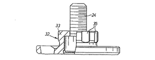
図2は、締付要素及び作業装置緊締ねじの一部断面側面図を示している。
図3は、釣り合い装置の断片的な断面図を示している。
図4は、図1におけるIII-III線に沿った断面図を示している。
図5は、後部ベアリングと出力スピンドルの保持手段の断面を断片的に示す拡大図である。
図6は、結合要素の拡大側面図である。
図面に示した動力工具は角度付グラインダ(angle grinder)であり、この角度付グラインダ(angle grinder)はハウジング10、回転モータ11、及び出力スピンドル12を備えている。出力スピンドル12は角度付駆動手段(angle drive)13によってモータ11に動力伝達的に連結されている。角度付駆動手段(angle drive)13は、モータ11に連結されたピニオン14と出力スピンドル12に連結されたベベルギヤ15とから成る。出力スピンドル12は前部ボールベアリング17及び後部ボールベアリング18によってハウジング10に対してジャーナル軸受けされている。前部ベアリング17のアウターレースはハウジング10の分離可能な壁部分19に支持されている。
出力スピンドル12はその前端に、ボール式自動釣り合い装置21及びホイール型研磨工具(図示せず)用の装着手段22が設けられている。
研磨工具装着手段22は、緊締ねじ24を支持するために出力スピンドル12内に形成されたネジ付き同軸孔23、径方向支持フランジ25、孔23と同軸のネジ付きソケット部分26、及びディスク型研磨工具支持要素28から成る。ディスク型研磨工具支持要素28には、ソケット部分26に噛合する後部ネジ付き首部29が形成されている。しかし、このネジのピッチは、緊締ねじ24のネジのピッチより大きくされ、これにより、緊締ねじ24と支持要素28とを一緒に緩めることができないようにしている。
また、支持要素28は、研磨後部における対応する中央開口と協働して中心決めを行う前向き筒状首部27を備えている。
さらに、支持要素28は、軸線方向にスプライン31が形成された同軸開口30を有する。締付要素32は、緊締ねじ24と協働するように配置され、支持要素28に対して研磨工具を締め付ける。締付要素32は筒状首部33を有し、この筒状首部33には支持要素28の開口30内に形成されたスプライン31と協働するためのスプライン35が設けられている。図4参照。
一方で、支持要素28と締付要素32との間のスプライン連結から成る組み付け動作のために、また、他方で、緊締ねじ24上のネジと支持要素28との間のピッチを異ならせているために、研磨工具は、研磨工具と出力スピンドル12の間に如何なる予期しない相対回転が生じても緩みが生じることは防止される。
支持要素28には平坦な径方向フランジ36が形成されている。このフランジ36は、出力スピンドル12上の支持フランジ25と研磨工具との間に挟まれる。支持フランジ25は、支持要素28と共に、緊締ねじ24の締付によって研磨工具を締め付ける時の研磨工具用の軸線方向支持手段を形成している。ある作業時間が経過し支持要素28が一定の長さまですり減ってきた時、それは簡単に新しいものと交換される。分離支持要素28を使用しなければ、出力スピンドル12のフランジ25は、それ自身が研磨工具による避けることのできない機械的摩擦にさらされる。出力スピンドル12全体の交換は、非常に高価な作業である。また、分離要素28は、異なる形状の研磨工具に対する装着手段22の改造を簡単にすることを可能にする。
研磨工具の使用寿命中に研磨工具に生じる力学的な不平衡力を補うことを目的とした釣り合い装置21は、円形周囲壁38、横断端壁39、環状閉鎖部材40、及び複数の鋼製ボール41から成り、前記鋼製ボール41は周囲壁38に沿って自由に移動できるように設けられている。ボール41を正確に案内するために、周囲壁38には、出力スピンドル12の回転軸線に対する中心決めと平滑さとに関して非常に高い品質を持つ部分的に球状な内側接触面43が設けられている。この種の釣り合い装置は既に公知であり、例えば、英国特許第832048号(GB 832048)に記載されている。
しかし、本発明による動力工具では、出力スピンドル12に加えて横断端壁39と周囲壁38とが相互に一体的に形成されており、横断端壁39が研磨工具装着手段22の径方向支持フランジ25を形成している。
また、出力スピンドル12には、ボール41の径方向内方に位置し、周囲壁38より軸線方向の長さが短い同軸円筒状面42が一体に形成されている。
環状閉鎖部材40は、実質的にL字状の輪郭の断面を有し、周囲壁38と円筒状面42との間に弾性膨脹力によって止められている。この位置に閉鎖部材40を固定するために、周囲壁38の後部には、閉鎖部材40の外側リム部分と協働する内側フランジ44が形成されており、これにより、閉鎖部材40は後方への軸線方向の動きに対してロックされる。図3を参照すると、閉鎖部材40と協働してシールするためのOリング45及び46が周囲壁38及び内側円筒状表面42の各々に形成された溝47及び48にはめ込まれている。
出力スピンドル12の端壁39の近くには、前部ボールベアリング17の内側ボールレースを配置するための径方向フランジ49及び円筒状表面50が形成されている。円筒状表面42の直径がベアリング17の外径より大きいので、閉鎖部材40を部分的にベアリング17の外側に配置することが可能になる。これは、釣り合い装置21に含まれた出力スピンドル12の前端部分が軸線方向に非常にコンパクトになることを意味する。
出力スピンドル12は、そのさらに後方に、別の径方向フランジ52、ベベルギヤ15を案内的に支持するための円筒状表面53、スプライン部分54、別の円筒状表面55、及びネジ部分56を有する。最後部の円筒状表面55は、後部ベアリング18の内側レースを案内的に支持し、ネジ部分56には締付ナット58が噛合する。
スプライン部分54上には環状結合要素59が支持されている。この結合要素59にはスプライン部分54と駆動連結するための内側スプラインと、前方に伸びる結合歯60とが形成されている。図6参照。結合歯60はベベルギヤ15のドック手段61と係合し、ベベルギヤ15と結合要素59との間の駆動トルクを伝達する。
後部ベアリング18の内側ボールレース、結合要素59、及びベベルギヤ15は、締付ナット58とフランジ52との間で堅固ユニットとして軸線方向に締め付けられる。この構成によって、ベベルギヤ15と出力スピンドル12の間を軽い締付で使用することが可能になり、出力スピンドル組立体の分解が容易になる。
ベベルギヤ15には前方に伸びる首部62が形成されており、この首部62上には、ハウジング10に設けられたシールリング64と協働するスリーブ要素63が設けられている。シールリング64の目的は、角度付駆動手段(angle drive)13に初めに塗布された潤滑グリスが漏れ出るのを防止することである。
出力スピンドル12は、後部ベアリング18、結合要素59、ベベルギヤ15、及び前部ベアリング17と共に、後部ベアリング18の下方に配置され、二つのネジ66によってハウジング10に固定された保持要素65によってハウジング10に軸線方向に締め付けられている。図4参照。締付力は、ベアリング18と保持要素65との間に挿入されたワッシャ型スプリング67によって後部ベアリング18の外側レースに加えられる。図5参照。
スプリング67によって加えられる軸線方向の締付力は、後部ベアリング18を介して出力スピンドル12に伝達され、さらに、出力スピンドル12、前部ベアリング17、及び壁部分19を介してハウジング10に伝達される。
【0007】
【発明の効果】
この構成によって、軸線方向に予め応力がかけられたボールベアリング17及び18はベアリングの遊びが無くなり、出力スピンドル12の回転精度が非常に高くなる。
【図面の簡単な説明】
【図1】本発明による角度付グラインダ(angle grinder)の出力端の長手方向断面図。
【図2】締付要素及び作業装置緊締ねじの一部断面側面図。
【図3】釣り合い装置の断片的な断面図。
【図4】図1におけるIII-III線に沿った断面図。
【図5】後部ベアリングと出力スピンドルの保持手段の断面を断片的に示す拡大図。
【図6】結合要素の拡大側面図。
【符号の説明】
10 ハウジング
11 回転モータ
12 出力スピンドル
13 角度付駆動手段(angle drive)
14 ピニオン
15 ベベルギヤ
17 前部ボールベアリング
18 後部ボールベアリング
19 壁部分
21 ボール式自動釣合い装置
22 装着手段
23 同軸孔
24 緊締ねじ
25 径方向支持フランジ
26 ネジ付きソケット部分
27 前向き筒状首部
28 ディスク型研磨工具支持要素
29 後部ネジ付き首部
30 開口
31 スプライン
32 締付要素
33 筒状首部
35 スプライン
36 径方向フランジ
38 円形周囲壁
39 横断端壁
40 環状閉鎖部材
41 鋼製ボール
42 円筒状面
43 内側接触面
44 内側フランジ
45 Oリング
46 Oリング
47 溝
48 溝
49 径方向フランジ
50 円筒状表面
52 径方向フランジ
53 円筒状表面
54 スプライン部分
55 円筒状表面
56 ネジ部分
58 締付ナット
59 結合要素
60 係合歯
61 ドック手段
62 首部
63 スリーブ要素
64 シールリング
65 保持要素
66 ネジ
67 ワッシャ型スプリング[0001]
BACKGROUND OF THE INVENTION
The present invention relates to a portable power tool for operating a rotary working device, and more particularly to a power tool of the type, such as a wheel-type polishing tool, with an output spindle that supports the rotary working device.
In particular, the present invention relates to a power tool of the above type comprising a ball-type balancing device interconnected to the output spindle for automatically balancing the output spindle and the working device attached thereto.
[0002]
[Prior art]
One problem inherent in this type of tool is that it is difficult to securely fix and perfectly center the balancing device relative to the output spindle. Another problem is to achieve a compact power tool structure in which the overall axial dimensions of the output spindle and the balance device are small and the axial distance between the working device and the front bearing of the output spindle is short.
[0003]
[Problems to be solved by the invention]
The main object of the present invention is to provide a power tool of the above type that solves the above problems.
[0004]
[Means for Solving the Problems]
According to the present invention, there is provided a housing, a rotary motor, an output spindle connected to the rotary motor and adapted to support a working device, and a ball race that is firmly connected to the output spindle. A portable power tool for operation of a rotary working device having a peripheral wall provided, a transverse end wall, and a ball-type balancing device including a plurality of balls that can move freely along the ball race. This is achieved by the peripheral wall and the transverse end wall being formed in one piece with the output spindle.
[0005]
DETAILED DESCRIPTION OF THE INVENTION
The ball-type balance device includes a coaxial cylindrical surface disposed radially inward of the ball and extending in the axial direction shorter than the ball race, and an annular closing member can be mounted between the peripheral wall and the coaxial cylindrical surface. .
The annular closure member may comprise a thin-walled sheet metal element that is preformed to be clamped by elastic expansion between the peripheral wall and the coaxial cylindrical surface.
The peripheral wall can comprise a peripheral flange that engages with the rim portion of the annular closure member.
The output spindle is journaled to the housing by a rear bearing and a front bearing, the front bearing is located adjacent to the front end of the output spindle, and the diameter of the coaxial cylindrical surface is approximately equal to the outer diameter of the front bearing. Or more.
The outer ball race of the rear bearing is held axially relative to the housing by a holding means that applies an axial clamping force to the outer ball race of the rear bearing, and the axial clamping force is applied to the inner ball race and the output of the rear and front bearings. It can be transmitted to the outer ball race of the front bearing via the spindle.
The retaining means may comprise a retaining element rigidly secured to the housing and a spring disposed between the retaining element and the outer ball race of the rear bearing to generate a tightening force on the rear bearing.
[0006]
【Example】
Hereinafter, preferred embodiments of the present invention will be described with reference to the accompanying drawings.
FIG. 1 shows a longitudinal section through the output end of an angle grinder according to the invention.
FIG. 2 shows a partial cross-sectional side view of the clamping element and the working device clamping screw.
FIG. 3 shows a fragmentary sectional view of the balancing device.
FIG. 4 shows a cross-sectional view taken along line III-III in FIG.
FIG. 5 is an enlarged view showing a fragmentary cross section of the holding means for the rear bearing and the output spindle.
FIG. 6 is an enlarged side view of the coupling element.
The power tool shown in the drawing is an angle grinder, and the angle grinder includes a
The
The abrasive tool mounting means 22 includes a threaded
The
Furthermore, the
On the one hand, for the assembly operation consisting of a spline connection between the
The
A
However, in the power tool according to the present invention, in addition to the
The
The
Near the
The
An
The inner ball race of the
A neck portion 62 extending forward is formed on the
The
The axial clamping force applied by the
[0007]
【The invention's effect】
With this configuration, the
[Brief description of the drawings]
FIG. 1 is a longitudinal cross-sectional view of an output end of an angle grinder according to the present invention.
FIG. 2 is a partial cross-sectional side view of a tightening element and a working device tightening screw.
FIG. 3 is a fragmentary cross-sectional view of a balancing device.
4 is a cross-sectional view taken along line III-III in FIG.
FIG. 5 is an enlarged view showing a section of the holding means for the rear bearing and the output spindle in a fragmentary manner.
FIG. 6 is an enlarged side view of the coupling element.
[Explanation of symbols]
DESCRIPTION OF
14
Claims (7)
上記出力スピンドル( 12 )が、前部ボールベアリング( 17 )を支持する第一の円筒状表面( 50 )、後部ボールベアリング( 18 )を支持する第二の円筒状表面( 55 )、及びベベルギア( 15 )を支持する第三の円筒状表面( 53 )により形成され、
出力スピンドル( 12 )の前端部に固定支持され、部分的に球状の接触表面( 43 )で形成された円形周囲壁( 38 )、横断端壁( 39 )、及び上記接触表面( 43 )に沿って自由且つ個別に移動可能な多数のボール( 41 )から成るボール式釣合い装置( 21 )と、
を備える回転作業装置の作動用携帯型動力工具において、
上記第一、第二及び第三の円筒状表面( 50, 55, 53 )及び上記円形周囲壁( 38 )が、上記出力スピンドル( 12 )と一体型に形成され、それにより固定した一部材を形成し、上記横断端壁( 39 )が作業工具の支持要素( 28 )用に軸方向を向いた支持肩部( 25 )を形成することを特徴とする回転作業装置の作動用携帯型動力工具。A housing (10), a rotary motor (11), an output spindle (12) journaled to the housing ( 10 ) and adapted to support the working device, and a pinion ( 14 ) connected to the motor ( 11 ) ) Including angled drive means ( 13 ) and a bevel gear ( 15 ) mounted on the output spindle ( 12 ) ,
The output spindle ( 12 ) includes a first cylindrical surface ( 50 ) that supports the front ball bearing ( 17 ), a second cylindrical surface ( 55 ) that supports the rear ball bearing ( 18 ), and a bevel gear ( 15 ) formed by a third cylindrical surface ( 53 ) supporting
A circular peripheral wall ( 38 ) fixedly supported at the front end of the output spindle ( 12 ) and formed by a partially spherical contact surface ( 43 ), a transverse end wall ( 39 ), and along the contact surface ( 43 ) A ball-type balancing device ( 21 ) consisting of a large number of freely movable and individually movable balls ( 41 ) ,
In a portable power tool for operating a rotary working device comprising:
The first, second and third cylindrical surfaces ( 50, 55, 53 ) and the circular peripheral wall ( 38 ) are formed integrally with the output spindle ( 12 ), thereby fixing one member A portable power tool for operating a rotary working device, characterized in that the transverse end wall ( 39 ) forms an axially oriented support shoulder ( 25 ) for the support element ( 28 ) of the work tool .
Applications Claiming Priority (2)
| Application Number | Priority Date | Filing Date | Title |
|---|---|---|---|
| SE9601734-8 | 1996-05-07 | ||
| SE9601734A SE510972C2 (en) | 1996-05-07 | 1996-05-07 | Portable power tool with balancing device |
Publications (2)
| Publication Number | Publication Date |
|---|---|
| JPH1071582A JPH1071582A (en) | 1998-03-17 |
| JP4058131B2 true JP4058131B2 (en) | 2008-03-05 |
Family
ID=20402479
Family Applications (1)
| Application Number | Title | Priority Date | Filing Date |
|---|---|---|---|
| JP11713797A Expired - Lifetime JP4058131B2 (en) | 1996-05-07 | 1997-05-07 | Portable power tools |
Country Status (5)
| Country | Link |
|---|---|
| US (1) | US5967243A (en) |
| EP (1) | EP0806268B1 (en) |
| JP (1) | JP4058131B2 (en) |
| DE (1) | DE69707968T2 (en) |
| SE (1) | SE510972C2 (en) |
Families Citing this family (24)
| Publication number | Priority date | Publication date | Assignee | Title |
|---|---|---|---|---|
| DE19851917A1 (en) * | 1998-11-11 | 2000-05-18 | Schaeffler Waelzlager Ohg | Clamping nut |
| US6165096A (en) * | 1999-03-12 | 2000-12-26 | Ingersoll-Rand Company | Self-shifting transmission apparatus |
| US6093128A (en) * | 1999-03-12 | 2000-07-25 | Ingersoll-Rand Company | Ratchet wrench having self-shifting transmission apparatus |
| DK1327497T3 (en) * | 2002-01-10 | 2006-07-31 | Black & Decker Inc | Gear housing |
| SE523780C2 (en) * | 2002-05-22 | 2004-05-18 | Atlas Copco Tools Ab | Portable power tool with grease lubricated angular gear whose grease-filled gearbox is divided by a disc-shaped element |
| SE523815C2 (en) * | 2002-05-22 | 2004-05-18 | Atlas Copco Tools Ab | Portable power tool with grease lubricated angular gear with separate grease distribution element |
| DE10357145A1 (en) * | 2003-12-06 | 2005-06-30 | Robert Bosch Gmbh | Hand grinder, mounting flange for a grinding tool and balancing unit |
| US8087977B2 (en) | 2005-05-13 | 2012-01-03 | Black & Decker Inc. | Angle grinder |
| EP1738865A1 (en) * | 2005-06-29 | 2007-01-03 | August Rüggeberg GmbH & Co. KG | Tool holder for rotatable tools |
| JP5027461B2 (en) * | 2006-08-25 | 2012-09-19 | 株式会社クボタ | Moor's cutting blade support device |
| DE102007000313A1 (en) * | 2007-06-06 | 2008-12-11 | Hilti Aktiengesellschaft | Electric hand tool with spindle locking device |
| DE102008022277A1 (en) * | 2008-04-25 | 2009-10-29 | Metabowerke Gmbh | Electric hand tool |
| US8230607B2 (en) | 2008-05-09 | 2012-07-31 | Milwaukee Electric Tool Corporation | Keyless blade clamp for a power tool |
| JP5484714B2 (en) * | 2008-11-20 | 2014-05-07 | 株式会社マキタ | Gear chamber seal structure |
| US8516885B1 (en) * | 2009-01-12 | 2013-08-27 | Doug Fortune | Rotating object dynamic balancing system and method |
| JP5243294B2 (en) * | 2009-02-18 | 2013-07-24 | 日東工器株式会社 | Rotating drive air tool |
| DE102010043188A1 (en) | 2010-10-29 | 2012-05-03 | Robert Bosch Gmbh | Discharge safety device |
| US9120213B2 (en) | 2011-01-21 | 2015-09-01 | Milwaukee Electric Tool Corporation | Powered ratchet wrench |
| EP2556922B1 (en) | 2011-08-09 | 2014-03-19 | C. & E. Fein GmbH | Power tool |
| SE540067C2 (en) * | 2016-04-25 | 2018-03-13 | Soedra Skogsaegarna Ekonomisk Foerening | Circular saw mounting device |
| CN107538439B (en) * | 2016-06-29 | 2023-09-12 | 苏州宝时得电动工具有限公司 | Vibration reduction system and method for swinging machine and swinging machine with vibration reduction system |
| US11691253B2 (en) | 2017-02-28 | 2023-07-04 | Milwaukee Electric Tool Corporation | Powered ratchet wrench with reversing mechanism |
| US10818450B2 (en) | 2017-06-14 | 2020-10-27 | Black & Decker Inc. | Paddle switch |
| US11413731B2 (en) | 2019-06-12 | 2022-08-16 | Milwaukee Electric Tool Corporation | Powered ratchet wrench |
Family Cites Families (13)
| Publication number | Priority date | Publication date | Assignee | Title |
|---|---|---|---|---|
| US1314005A (en) * | 1919-08-26 | Automatic balancing means fob high-speed botobs | ||
| GB832048A (en) * | 1958-03-14 | 1960-04-06 | Georg Schafer | Balancing device for rotating bodies |
| US3731556A (en) * | 1971-11-17 | 1973-05-08 | Cincinnati Milacron Inc | Dynamic balancing apparatus |
| US3799619A (en) * | 1972-05-18 | 1974-03-26 | Wagner K | Vibration dampening assembly |
| GB1471706A (en) * | 1974-10-30 | 1977-04-27 | Chrysler Uk | Balancing rotors |
| GB1498968A (en) * | 1974-12-19 | 1978-01-25 | Bosch Gmbh Robert | Rotary power tool such as a power wrench |
| US4653338A (en) * | 1985-02-11 | 1987-03-31 | Hall Surgical Division Of Zimmer, Inc. | Apparatus for driving a member |
| SU1553867A1 (en) * | 1988-02-29 | 1990-03-30 | Предприятие П/Я В-2750 | Arrangement for damping vibrations of grinding wheel |
| US5111713A (en) * | 1989-12-18 | 1992-05-12 | International Business Machines Corporation | Dynamically balanced rotary unit |
| US5060771A (en) * | 1990-05-15 | 1991-10-29 | The Aro Corporation | Adjustable automatic shut-off mechanism for lever or trigger controlled air tool |
| DE4105340C2 (en) * | 1991-02-21 | 1993-09-30 | Atlas Copco Elektrowerkzeuge | Hand-held angle grinder with a brake arrangement and a device having a spur toothing or similar form-fitting connection for securing the clamping flange against automatic loosening during the braking process |
| SE9201991L (en) * | 1992-06-29 | 1993-12-30 | Atlas Copco Tools Ab | Portable grinder |
| SE506309C2 (en) * | 1993-05-19 | 1997-12-01 | Atlas Copco Tools Ab | Mounting device for grinding wheels |
-
1996
- 1996-05-07 SE SE9601734A patent/SE510972C2/en not_active IP Right Cessation
-
1997
- 1997-05-01 US US08/847,041 patent/US5967243A/en not_active Expired - Lifetime
- 1997-05-02 EP EP97850072A patent/EP0806268B1/en not_active Expired - Lifetime
- 1997-05-02 DE DE69707968T patent/DE69707968T2/en not_active Expired - Fee Related
- 1997-05-07 JP JP11713797A patent/JP4058131B2/en not_active Expired - Lifetime
Also Published As
| Publication number | Publication date |
|---|---|
| DE69707968D1 (en) | 2001-12-13 |
| DE69707968T2 (en) | 2002-06-27 |
| JPH1071582A (en) | 1998-03-17 |
| SE9601734L (en) | 1997-11-08 |
| SE9601734D0 (en) | 1996-05-07 |
| EP0806268A1 (en) | 1997-11-12 |
| SE510972C2 (en) | 1999-07-19 |
| US5967243A (en) | 1999-10-19 |
| EP0806268B1 (en) | 2001-11-07 |
Similar Documents
| Publication | Publication Date | Title |
|---|---|---|
| JP4058131B2 (en) | Portable power tools | |
| JP4051102B2 (en) | Portable power polishing equipment | |
| CA1313313C (en) | Chucking device for axially clamping a tool, in particular a disc | |
| US20070181322A1 (en) | Power tool with angle drive and pinion adjustment | |
| EP1752242A2 (en) | Processing method for brake rotor-equiped wheel bearing devices | |
| US20060177168A1 (en) | Rotary apparatus | |
| US20090018001A1 (en) | Protection device for a motor spindle | |
| KR930007538B1 (en) | Traction drive tool adapter | |
| US5941764A (en) | Shaft-equipped grinder used in a mold-graving device | |
| US5875550A (en) | Steer spindle bullet tool | |
| JPH08336702A (en) | Portable flange seal surface processing machine | |
| JP2562052B2 (en) | Inner bead grinding machine for small diameter pipes | |
| GB2118684A (en) | Securing rotors to shafts | |
| JPH08200384A (en) | Joint unit for driving wheel | |
| JP2004122357A (en) | Molding pulley assembly for belt notching machine | |
| JPH07308326A (en) | Integral type bar tube and bearing assembly | |
| SE510970C2 (en) | Portable grinding machine for driving rotating grinding tool | |
| US7905165B1 (en) | Adapter assembly for hubbed rotor | |
| JPH09271854A (en) | Motor-operated enlarging tool | |
| JPH071291A (en) | Tool holder | |
| EP0316451A4 (en) | Device for abrasive machining | |
| CN212947015U (en) | Poor spindle housing of section of good performance | |
| JP3152639B2 (en) | Bearing structure of dental handpiece | |
| JPH03142142A (en) | Spindle structure of machine tool | |
| KR900008002Y1 (en) | Disc type center |
Legal Events
| Date | Code | Title | Description |
|---|---|---|---|
| A621 | Written request for application examination |
Free format text: JAPANESE INTERMEDIATE CODE: A621 Effective date: 20040430 |
|
| A131 | Notification of reasons for refusal |
Free format text: JAPANESE INTERMEDIATE CODE: A131 Effective date: 20060830 |
|
| A601 | Written request for extension of time |
Free format text: JAPANESE INTERMEDIATE CODE: A601 Effective date: 20061130 |
|
| A602 | Written permission of extension of time |
Free format text: JAPANESE INTERMEDIATE CODE: A602 Effective date: 20061206 |
|
| A521 | Request for written amendment filed |
Free format text: JAPANESE INTERMEDIATE CODE: A523 Effective date: 20070228 |
|
| A131 | Notification of reasons for refusal |
Free format text: JAPANESE INTERMEDIATE CODE: A131 Effective date: 20070801 |
|
| A521 | Request for written amendment filed |
Free format text: JAPANESE INTERMEDIATE CODE: A523 Effective date: 20071030 |
|
| TRDD | Decision of grant or rejection written | ||
| A01 | Written decision to grant a patent or to grant a registration (utility model) |
Free format text: JAPANESE INTERMEDIATE CODE: A01 Effective date: 20071121 |
|
| A61 | First payment of annual fees (during grant procedure) |
Free format text: JAPANESE INTERMEDIATE CODE: A61 Effective date: 20071217 |
|
| R150 | Certificate of patent or registration of utility model |
Free format text: JAPANESE INTERMEDIATE CODE: R150 |
|
| FPAY | Renewal fee payment (event date is renewal date of database) |
Free format text: PAYMENT UNTIL: 20101221 Year of fee payment: 3 |
|
| FPAY | Renewal fee payment (event date is renewal date of database) |
Free format text: PAYMENT UNTIL: 20101221 Year of fee payment: 3 |
|
| FPAY | Renewal fee payment (event date is renewal date of database) |
Free format text: PAYMENT UNTIL: 20111221 Year of fee payment: 4 |
|
| FPAY | Renewal fee payment (event date is renewal date of database) |
Free format text: PAYMENT UNTIL: 20111221 Year of fee payment: 4 |
|
| FPAY | Renewal fee payment (event date is renewal date of database) |
Free format text: PAYMENT UNTIL: 20121221 Year of fee payment: 5 |
|
| FPAY | Renewal fee payment (event date is renewal date of database) |
Free format text: PAYMENT UNTIL: 20121221 Year of fee payment: 5 |
|
| FPAY | Renewal fee payment (event date is renewal date of database) |
Free format text: PAYMENT UNTIL: 20131221 Year of fee payment: 6 |
|
| R250 | Receipt of annual fees |
Free format text: JAPANESE INTERMEDIATE CODE: R250 |
|
| R250 | Receipt of annual fees |
Free format text: JAPANESE INTERMEDIATE CODE: R250 |
|
| R250 | Receipt of annual fees |
Free format text: JAPANESE INTERMEDIATE CODE: R250 |
|
| R250 | Receipt of annual fees |
Free format text: JAPANESE INTERMEDIATE CODE: R250 |
|
| EXPY | Cancellation because of completion of term |