JP4057803B2 - Manufacturing method of semiconductor device - Google Patents
Manufacturing method of semiconductor device Download PDFInfo
- Publication number
- JP4057803B2 JP4057803B2 JP2001275593A JP2001275593A JP4057803B2 JP 4057803 B2 JP4057803 B2 JP 4057803B2 JP 2001275593 A JP2001275593 A JP 2001275593A JP 2001275593 A JP2001275593 A JP 2001275593A JP 4057803 B2 JP4057803 B2 JP 4057803B2
- Authority
- JP
- Japan
- Prior art keywords
- semiconductor device
- water
- insulating film
- device surface
- polishing pad
- Prior art date
- Legal status (The legal status is an assumption and is not a legal conclusion. Google has not performed a legal analysis and makes no representation as to the accuracy of the status listed.)
- Expired - Fee Related
Links
Images


Classifications
-
- H—ELECTRICITY
- H01—ELECTRIC ELEMENTS
- H01L—SEMICONDUCTOR DEVICES NOT COVERED BY CLASS H10
- H01L21/00—Processes or apparatus adapted for the manufacture or treatment of semiconductor or solid state devices or of parts thereof
- H01L21/02—Manufacture or treatment of semiconductor devices or of parts thereof
- H01L21/02041—Cleaning
- H01L21/02057—Cleaning during device manufacture
- H01L21/0206—Cleaning during device manufacture during, before or after processing of insulating layers
- H01L21/02063—Cleaning during device manufacture during, before or after processing of insulating layers the processing being the formation of vias or contact holes
-
- H—ELECTRICITY
- H01—ELECTRIC ELEMENTS
- H01L—SEMICONDUCTOR DEVICES NOT COVERED BY CLASS H10
- H01L21/00—Processes or apparatus adapted for the manufacture or treatment of semiconductor or solid state devices or of parts thereof
- H01L21/02—Manufacture or treatment of semiconductor devices or of parts thereof
- H01L21/04—Manufacture or treatment of semiconductor devices or of parts thereof the devices having at least one potential-jump barrier or surface barrier, e.g. PN junction, depletion layer or carrier concentration layer
- H01L21/18—Manufacture or treatment of semiconductor devices or of parts thereof the devices having at least one potential-jump barrier or surface barrier, e.g. PN junction, depletion layer or carrier concentration layer the devices having semiconductor bodies comprising elements of Group IV of the Periodic System or AIIIBV compounds with or without impurities, e.g. doping materials
- H01L21/30—Treatment of semiconductor bodies using processes or apparatus not provided for in groups H01L21/20 - H01L21/26
- H01L21/302—Treatment of semiconductor bodies using processes or apparatus not provided for in groups H01L21/20 - H01L21/26 to change their surface-physical characteristics or shape, e.g. etching, polishing, cutting
- H01L21/304—Mechanical treatment, e.g. grinding, polishing, cutting
-
- H—ELECTRICITY
- H01—ELECTRIC ELEMENTS
- H01L—SEMICONDUCTOR DEVICES NOT COVERED BY CLASS H10
- H01L21/00—Processes or apparatus adapted for the manufacture or treatment of semiconductor or solid state devices or of parts thereof
- H01L21/02—Manufacture or treatment of semiconductor devices or of parts thereof
- H01L21/02041—Cleaning
- H01L21/02057—Cleaning during device manufacture
- H01L21/02068—Cleaning during device manufacture during, before or after processing of conductive layers, e.g. polysilicon or amorphous silicon layers
- H01L21/02074—Cleaning during device manufacture during, before or after processing of conductive layers, e.g. polysilicon or amorphous silicon layers the processing being a planarization of conductive layers
-
- H—ELECTRICITY
- H01—ELECTRIC ELEMENTS
- H01L—SEMICONDUCTOR DEVICES NOT COVERED BY CLASS H10
- H01L21/00—Processes or apparatus adapted for the manufacture or treatment of semiconductor or solid state devices or of parts thereof
- H01L21/02—Manufacture or treatment of semiconductor devices or of parts thereof
- H01L21/04—Manufacture or treatment of semiconductor devices or of parts thereof the devices having at least one potential-jump barrier or surface barrier, e.g. PN junction, depletion layer or carrier concentration layer
- H01L21/18—Manufacture or treatment of semiconductor devices or of parts thereof the devices having at least one potential-jump barrier or surface barrier, e.g. PN junction, depletion layer or carrier concentration layer the devices having semiconductor bodies comprising elements of Group IV of the Periodic System or AIIIBV compounds with or without impurities, e.g. doping materials
- H01L21/30—Treatment of semiconductor bodies using processes or apparatus not provided for in groups H01L21/20 - H01L21/26
- H01L21/31—Treatment of semiconductor bodies using processes or apparatus not provided for in groups H01L21/20 - H01L21/26 to form insulating layers thereon, e.g. for masking or by using photolithographic techniques; After treatment of these layers; Selection of materials for these layers
- H01L21/3205—Deposition of non-insulating-, e.g. conductive- or resistive-, layers on insulating layers; After-treatment of these layers
- H01L21/321—After treatment
- H01L21/32115—Planarisation
- H01L21/3212—Planarisation by chemical mechanical polishing [CMP]
-
- H—ELECTRICITY
- H01—ELECTRIC ELEMENTS
- H01L—SEMICONDUCTOR DEVICES NOT COVERED BY CLASS H10
- H01L21/00—Processes or apparatus adapted for the manufacture or treatment of semiconductor or solid state devices or of parts thereof
- H01L21/70—Manufacture or treatment of devices consisting of a plurality of solid state components formed in or on a common substrate or of parts thereof; Manufacture of integrated circuit devices or of parts thereof
- H01L21/71—Manufacture of specific parts of devices defined in group H01L21/70
- H01L21/768—Applying interconnections to be used for carrying current between separate components within a device comprising conductors and dielectrics
- H01L21/76838—Applying interconnections to be used for carrying current between separate components within a device comprising conductors and dielectrics characterised by the formation and the after-treatment of the conductors
- H01L21/7684—Smoothing; Planarisation
Description
【0001】
【発明の属する技術分野】
本発明は、pn接合を介して電気的に接続する導電体が露出する状態の半導体装置に対して薬液処理を行う半導体装置の製造方法に関する。
【0002】
【従来の技術】
半導体装置のP−Nジャンクションに光が当たると、ホールとエレクトロンが発生する特性を持っている。現在、製造工程の途中で、ホールとエレクトロンが発生することで問題が生じている。図8を用いて、半導体装置の製造工程の途中で、P−Nジャンクションに光が照射されることで生じる問題を説明する。図8は半導体装置の製造工程におけるダマシン工程を示す工程断面図である。
【0003】
図8(a)において11はSi基板、12はn型にドープされたn+ 型ウェル、13はp型にドープされたp+ 型ウェル、14は絶縁膜、15はバリアメタル、16a,16bは金属配線、81はスラリーである。配線16aはp+ 型ウェル13に、配線16bはn+ 型ウェル12にそれぞれ接続している。配線16aと配線16bとはデバイス表面に露出して離れてパターニングされているが、図8(a)に示す状態ではバリアメタル15はデバイス表面にまだ残っており、このデバイスに光が当たっても、表面でバリアメタル15を介して電気的に導通しているため、発生したホールとエレクトロンはデバイス内で消化される。
【0004】
しかしCMPが進行し、図8(b)に示すようにバリアメタル15がデバイス表面から除去されると、n+ 型ウェル12に接続する配線16b表面では正イオンの析出が起こり、一方p+ 型ウェル13に接続する配線16a表面では金属の溶解が起こるという、いわゆる光コロージョンが発生する。このため、金属の変形や変質が起こり,その後の工程が行えなくなったり,デバイス特性自体も損なわれたりしていた。
【0005】
ここではCMP工程を例に挙げたが、図8(b)に示す構造段階と同様のデバイスを溶液処理する工程においては、上記と同じメカニズムの溶解・析出反応が起こり得る問題である。例えばヴィアホールを開口した後の薬液処理工程などがある。
【0006】
【発明が解決しようとする課題】
上述したように、pn接合で接合するp型半導体層及びn型半導体層上にそれぞれ導電体が形成された状態で、デバイス面にスラリー薬液等の電解質を含む薬液が供給され、pn接合に光が照射されると、光コロージョンが発生するという問題があった。
【0007】
本発明の目的は、pn接合を介して電気的に接続する導電体が露出する状態の半導体装置に対して薬液処理を行う際、光コロージョンの発生を抑制し得る半導体装置の製造方法を提供することにある。
【0008】
【課題を解決するための手段】
本発明は、上記目的を達成するために以下のように構成されている。
【0009】
(1)本発明に係わる半導体装置の製造方法は、pn接合するp型半導体層及びn型半導体層が形成された半導体基板のデバイス面上に複数の開口を有する絶縁膜と、前記開口内及び前記絶縁膜上に形成され、前記p型半導体層及びn型半導体層に電気的に接続する導電体とを具備する半導体装置の前記デバイス面を下向きにして、該デバイス面に研磨パッド表面を当接させた状態で、該研磨パッドと該デバイス面との間にスラリーを供給しつつ、前記半導体装置と前記研磨パッドとを相対的に移動させて、前記導電体に対して化学的機械研磨を行って、前記絶縁膜上の導電体を除去し、前記複数の開口内にそれぞれ配線を形成する工程と、前記研磨パッド表面に前記半導体装置のデバイス面を当接させた状態で、該研磨パッドと該デバイス面との間に、純水若しくは超純水の電解水、ガスを溶解させた水、又はOHラジカルを含む水を供給する工程と、前記半導体装置のデバイス面の前記研磨パッドへの当接を解除する工程とを具備することを特徴する。
【0010】
(2)本発明に係わる半導体装置の製造方法は、pn接合するp型半導体層とn型半導体層とを含む半導体基板のデバイス面上に形成された複数の第1の開口を有する第1の絶縁膜と、前記第1の開口内に形成され、前記pn接合を介して電気的に接続する複数の導電体と、第1の絶縁膜及び前記導電体上に形成された第2の絶縁膜とを具備する半導体装置の第2の絶縁に前記複数の導電体が露出する第2の開口を形成する工程と、前記半導体装置のデバイス面に電解質を含む薬液を供給する工程と、前記薬液の供給中及び供給後の少なくとも一方の時に前記半導体装置のデバイス面に、純水若しくは超純水の電解水、ガスを溶解させた水、又はOHラジカルを含む水を供給する工程とを具備することを特徴とする。
【0012】
【発明の実施の形態】
本発明の実施の形態を以下に図面を参照して説明する。
(第1の実施形態)
本実施形態では、図1(a)に示す構造の半導体装置に対して、CMP処理を行って、図1(b)に示すようにダマシン配線を形成する工程について説明する。図1は、本発明の第1の実施形態に係わる半導体装置の製造工程を示す工程断面図である。
【0013】
先ず、図1(a)に示す状態の半導体装置の構成について説明する。図1(a)に示すように、Si基板11の表面にn+ 型ウェル12が形成されている。n+ 型ウェル12上に、n+ 型ウェル12とpn接合を形成するp+ 型ウェル13が形成されている。Si基板11,n+ 型ウェル12、及びp+ 型ウェル13上に絶縁膜14が形成されている。絶縁膜14には、n+ 型ウェル12又はp+ 型ウェル13が露出する溝が形成されている。絶縁膜14及びn+ 型ウェル12及びp+ 型ウェル13の表面にバリアメタル15が形成されている。バリアメタル15上にデバイス全面に成膜された銅(導電体)16が形成されている。
【0014】
本実施形態に係わる半導体装置の製造工程を図2及び図3を用いて説明する。図2は、本発明の第1の実施形態に係わる半導体装置の製造工程の説明に用いるフローチャートである。図3は、本発明の第1の実施形態に係わる半導体装置の製造工程の一部を模式的に示す図である。
【0015】
(ステップS101:一次CMP処理)
図3(a)に示すように、デバイス製造途中である図1(a)に示した半導体装置のウェハ33が、CMP装置のウェハキャリア34に保持された後、デバイス面(銅16形成面)を下にして、研磨定盤32の上面に張られた研磨パッド31に押圧される。そして、研磨パッド31上にノズルからスラリー35を供給しつつ、研磨定盤32及びウェハキャリア34を自転させて、銅16のCMP処理を行う。絶縁膜14上のバリアメタル15が露出したら、スラリー35の供給を停止する。
【0016】
(ステップS102:二次CMP処理)
次いで、デバイス面を研磨パッド31に押圧させた状態で、一次CMP処理(ステップS101)と異なるスラリー35を供給しつつ、研磨定盤32及びウェハキャリア34を自転させて、バリアメタル15のCMP処理を行う。バリアメタル15が除去され、絶縁膜14が露出したら、スラリー35の供給を停止する。
【0017】
この時、バリアメタル15が除去されて、図1(b)に示すように、p+ 型ウェル13に接続する配線16aと、n+ 型ウェル12に接続する配線16bとが,デバイス表面で導通していない状態になっている。そこで二次CMP後の研磨パッド31から外すときに、光コロージョンを防止することが重要になる。
【0018】
(ステップS103:スラリー・研磨屑除去処理)
次いで、デバイス面に付着しているスラリー及び研磨屑を除去し、ウェハ33の洗浄を行う。ここでは、デバイス面を研磨パッド31に押圧させた状態で、薬液36および純水37を研磨パッド31上に供給しつつ、研磨定盤32及びウェハキャリア34を自転させて、ウェハのデバイス面を洗浄する。
【0019】
(ステップS104:機能水供給)
次いで、ウェハ33のデバイス面の洗浄を行い、ステップS103で用いた薬液36を除去する。ここでは、デバイス面を研磨パッド31に押圧させた状態で、機能水として純水を電気分解した電解水(機能水)38を研磨パッド31上に供給しつつ、研磨定盤32及びウェハキャリア34を自転させて、デバイス面を洗浄する。
【0020】
ステップS103,104では、ウェハ33のデバイス面は研磨パッド31に押圧された状態なので、pn接合に光が照射されることがないので、光コロージョンが発生することがない。
【0021】
(ステップS105:ウェハキャリアからの取り外し)
洗浄処理終了後、ウェハ33をウェハキャリア34から取り外し、ウェハ33のデバイス面を上向きにする。この時、pn接合に光が照射され、光コロージョンが発生する可能性が最も高い。然るに、本実施形態では、洗浄処理で機能水38を用いたので、ウェハ33のデバイス面には電解水38が付着しており、光コロージョンの発生を防止することができる。電解水38による光コロージョンの発生防止効果については後述する。
【0022】
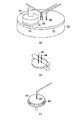
(ステップS106:スクラブ洗浄処理)
図3(b)に示すように、ウェハ33の両面を洗浄できるようなロールブラシ39によって、ウェハ33のスクラブ洗浄を行う。この時、ロールブラシ39は回転しており、ウェハ33も回転機構(図示せず)によって回転させられている。洗浄液として通常は純水または純水希釈した洗浄薬液を用いるが、本実施形態では、純水に代えて、電解水38を用いる。なお、電解水38と純水を併用してもよいが、電解水の使用時間が長く、且つ使用濃度が高いほうが、光コロージョンの抑制効果は大きい。
【0023】
また、図中ではウェハ33とロールブラシ39は水平に置かれているが、垂直向きでも構わない。またこの洗浄ステップは1ステップでなく、2ステップ以上あっても構わない。さらに、ブラシの形状もロール型に限られるものではないし、ブラシなどのスクラブ部材に代えて、メガソニック洗浄などの非接触洗浄を用いる場合でも、純水の代わりに電解水を用いると光コロージョンを防止することができる。
【0024】
(ステップS107:乾燥処理)
最後にウェハ33に対して乾燥処理が行われる。図3(c)に示すように、ウェハ33がウエーハチャック40によって保持された状態で、ウェハ33を高速回転させることによって、乾燥処理が行われる。乾燥処理を行う前にウェハ33に対してリンス処理を行ってもよいが、この場合も通常のリンス処理に用いられる純水に代えて電解水38を用いることが光コロージョンの防止に有効である。
【0025】
以上の説明では機能水として電解水を用いた場合について取り上げたが、機能水として、酸素等のガスを溶解させた水、OHラジカル等のラジカルを含む水を用いても同様の効果が期待できる。
【0026】
電解水が光コロージョンの発生防止に有効である理由を、半導体装置と溶液を流れる電流を模式的に表した図4を用いて説明する。P−N接合部には0.7V以下程度の電位差により起電力51が存在する。デバイス表面には、配線16a、16bが露出しており、溶液55に接している。この時、配線16a,16b表面には、溶液と配線間での反応の起こりにくさを抵抗で表した分極抵抗52(52a,52b)が存在し、また溶液が配線近傍で電気二重層を作るために電気二重層容量53(53a,53b)が存在するとモデル化できる。さらに、溶液自体の抵抗成分54が存在する。電気化学的にモデル化したこの回路において、回路に流れる電流を小さくするには、まずはP−N接合部での起電力51をなくせば良い。そのためには系全体を遮光すればよいが、装置構成上、困難な場合も多い。その場合でも、溶液抵抗54もしくは分極抵抗52を大きくすれば、回路に流れる電流値を抑えることができる。
【0027】
溶液抵抗54を大きくするためには、溶液中の電解質を少なくする必要があるが、エッチング溶液やCMPで用いるスラリーでは電解質によって反応が進行するので、電解質を除去することは難しい。しかし、エッチングやCMPの後にデバイス表面をすばやくそこで電解質を含まない溶液に置換した状態であれば、処理後に不要な電流が回路に流れず、光コロージョンの発生を抑えることができる。
【0028】
電解質を含まない溶液とは、一般には脱イオン化した超純水であるが、純水又は超純水の電解水(以下、超純電解イオン水という)、ガス溶解水でも超純水と同等以上の抑制効果が得られる。超純電解イオン水、ガス溶解水では超純水より大量のガスが液中に溶解しているため、またCuの表面酸化が進行して、二重層容量53の容量も大きくなるために、より電流が流れにくくなっていると考えられる。OHラジカルを含む水の場合は、超純水、さらにはガス溶解水よりCuの表面酸化が進行しやすくなり、電流が流れにくくなる。超純電解イオン水の場合も、メガソニックノズルを通して供給することにより、OHラジカルを効率良く発生させることができる。そこで、装置構成上可能ならば、ステップS106においてメガソニック洗浄と超純電解イオン水を組み合わせることが有効である。
【0029】
さらに機能水の特長として、デバイスの表面に付着した硫黄化合物などの汚染を純水よりもすばやく置換できる効果がある。硫黄化合物の例を述べると、硫黄化合物はCMPスラリー成分として用いられる場合があるほか、CMP以外の一般的な酸処理の薬液にも含まれ、さらにはレジスト成分にも含まれるため、ヴィアホール開口後の残渣中にも存在する。また硫黄化合物は、大気雰囲気に一般に数10〜数100ppb含まれ、これらがCuの表面に付着すると、局所電池が作られることによりコロージョンが発生する。すなわちCu表面に硫黄化合物などの汚染物が付着した場合、汚染箇所の電位が周辺より高くなり、コロージョンを誘発しやすくなると考えられる。同様に、光コロージョンでも、汚染箇所があれば電位差が大きくなるので、その部分から光コロージョンが進行しやすくなる。これらの汚染はステップS103でのスラリー・研磨屑処理において十分除去しきれない場合があるが、機能水を使用すれば残った汚染をすばやく除去できるので、このようなコロージョンを防ぐことができる。
【0030】
(第2の実施形態)
光コロージョンの発生を抑制するためには、図4に示す等価回路の分極抵抗52を大きくすることが有効であることを第1の実施形態で述べた。この分極抵抗52を大きくするためには、配線表面を不動態化することも利用できる。具体的には、配線表面に有機物を吸着させる、配線表面を酸化させる、と言った方法である。本実施形態では、配線表面に有機物を吸着させて、光コロージョンを防止する方法について説明する。
【0031】
本実施形態に係わる半導体装置の製造工程を図5及び図6を用いて説明する。図5は、本発明の第2の実施形態に係わる半導体装置の製造工程の説明に用いるフローチャートである。図6は、本発明の第2の実施形態に係わる半導体装置の製造工程の一部を模式的に示す図である。なお、図5において図2に示すフローチャートにおける処理と同一の処理には同一符号を付し、その説明を省略する。また、図6において図3と同一な部位には同一符号を付し、その説明を省略する。
【0032】
(ステップS204:洗浄処理)
二次CMP処理(ステップS102)終了後、研磨パッド31上に、BTA(ベンゾトリアゾール)など有機物を添加した有機物添加溶液48を供給する。有機物添加溶液48を供給するタイミングは、洗浄対象やスラリーの種類によって異なる。例えば、薬液36を供給してデバイスの配線上に残ったスラリーや研磨屑等の異物等を除去した後、できるだけ速やかに有機物添加溶液48を供給する、または薬液36の供給と同時に有機物添加溶液48を供給する。すると、Cuやバリアメタル上に有機物が吸着して、デバイス表面での電荷のやりとりを妨げるので、光コロージョンを防ぐことができる。
【0033】
同様に、第1の実施形態におけるスクラブ洗浄処理(ステップS106)と同様の、スクラブ洗浄処理(ステップS206)においても、図6(b)に示すように、洗浄薬液36と共に有機物添加溶液48を供給する。
【0034】
また、乾燥処理(ステップS107)を行う前に、図6(c)に示すように、必要があれば有機物添加溶液48を供給してもよいが、純水リンスでは吸着した有機物はほとんど取れないので改めて有機物添加溶液を供給する必要性は少ない。また、銅の表面に有機物が付着しているので、有機物添加溶液ではなく純水リンスのみで構わない。
【0035】
有機溶液としては、BTA以外に、ベンズイミダゾール(BI)、N−Nジエチルジチオカルバミン酸アンモニウム、クペロン、ピコリン酸等の有機物を添加させた溶液を用いても良い。
【0036】
(第3の実施形態)
図7は、本発明の第3の実施形態に係わる半導体装置の製造工程を示す工程断面図である。図7において、図1と同一な部位には同一符号を付し、その説明を省略する。
【0037】
図7(a)に示すように、配線16a,16b、及び絶縁膜14上に層間絶縁膜71を形成する。次いで、層間絶縁膜71上に図示されないレジストパターンを形成する。レジストパターンをマスクにエッチング性ガスを用いたRIE法により層間絶縁膜71をエッチングして、底面に配線16a,16bが露出するヴィアホール72a,72bを形成する。そして、レジストパターンを除去する。
【0038】
次いで、図7(b)に示すように、デバイス面に薬液73を供給して薬液処理を行う。層間絶縁膜71にヴィアホール72a,72bを開口した後、レジスト残渣、配線又は絶縁膜の成分がガスと反応した反応性生成物がヴィアホール内に付着していることが多い。そのため、ヴィアホール72a,72b形成後の後処理として、反応生成物を除去するための薬液処理が一般的に行われる。
【0039】
この薬液処理では、薬液73がヴィアホール72a,72b内部で配線表面に接している。薬液73は酸・アルカリ溶液である場合が多いので、この状態でデバイスに光が当たると、やはりpn接合部でホールとエレクトロンが発生し、配線の溶解・析出が起こる。そこで薬液処理室は暗室であることが望ましい。
【0040】
次いで、図7(c)に示すように、第1の実施形態で説明した機能水74を用いた洗浄処理を行う。この洗浄処理で、機能水74がヴィアホール72a,72b内部の薬液73を置換し、配線16a,16bの溶解・析出反応の防止効果がある。
【0041】
理想的には洗浄処理も暗室で行えば問題ないが、洗浄室は暗室にするのが困難な場合が多い。ウェハの出し入れが行われるロード・アンロード室は、通常は外から見えるように透明な窓がついているので、洗浄処理装置の内部全部を暗くすることは実際には難しい。洗浄処理室は薬液処理室と通常は別であり、またアンロード室により近い位置にある洗浄処理室には、光が漏れることがある。そこで純水洗浄に替えて、機能水を使用することが望ましい。
【0042】
また、薬液処理においても、薬液の種類によっては、機能水と薬液を混合することにより、配線の表面電位が変化して、溶解・析出反応の抑止効果がある。そこで、薬液73の希釈液として機能水を用いてもよい。
【0043】
なお、本発明は、上記実施形態に限定されるものではない。例えば、上記各実施形態では、導電体として銅を用いていたが、導電体としては、シリコン、アルミニウム,タングステン,金,及び銀の少なくとも一つを含む金属或いは合金を用いることができる。また、上記各実施形態においては、p型半導体及びn型半導体に直接接続される第1層のダマシン配線について光コロージョンを防止する例を示したが、第2層以上の上層ダマシン配線に対して本発明を適用しても良い。その他、本発明は、その要旨を逸脱しない範囲で、種々変形して実施することが可能である。
【0044】
【発明の効果】
以上説明したように本発明によれば、CMP工程によりpn接合を介して電気的に接続する導電体がデバイス面に露出する状態の半導体装置を形成した後、デバイス面を研磨パッドに当接させた状態で、機能水を供給することで、光コロージョンを防止することができる。
【0045】
又、本発明によれば、pn接合を介して電気的に接続する導電体がデバイス面に露出する開口を有する層間絶縁膜を形成した後、薬液処理を行う際、処理中,又は処理後に機能水をデバイス面に供給することで、光コロージョンを防止することができる。
【0046】
また、本発明によれば、pn接合を介して電気的に接続する導電体が露出する状態の半導体装置に対して薬液処理を行う際、処理前,処理中,又は処理後に前記導電体の表面に有機物を吸着させることによって、光コロージョンを防止することができる。
【図面の簡単な説明】
【図1】第1の実施形態に係わる半導体装置の製造工程を示す工程断面図。
【図2】第1の実施形態に係わる半導体装置の製造工程の説明に用いるフローチャート。
【図3】第1の実施形態に係わる半導体装置の製造工程の一部を模式的に示す図。
【図4】第1の実施形態に係わる光コロージョンの発生防止に有効である半導体装置と溶液を流れる電流を模式的に表した図。
【図5】第2の実施形態に係わる半導体装置の製造工程の説明に用いるフローチャート。
【図6】第2の実施形態に係わる半導体装置の製造工程の一部を模式的に示す図。
【図7】第3の実施形態に係わる半導体装置の製造工程を示す工程断面図。
【図8】半導体装置の製造工程におけるダマシン工程を示す工程断面図。
【符号の説明】
11…基板
12…n型ウェル
13…p型ウェル
14…絶縁膜
15…バリアメタル
16…銅[0001]
BACKGROUND OF THE INVENTION
The present invention relates to a method of manufacturing a semiconductor device in which a chemical treatment is performed on a semiconductor device in a state where a conductor electrically connected through a pn junction is exposed.
[0002]
[Prior art]
When light hits a PN junction of a semiconductor device, it has a characteristic that holes and electrons are generated. Currently, problems occur due to the generation of holes and electrons during the manufacturing process. With reference to FIG. 8, a problem that occurs when light is applied to a PN junction during the manufacturing process of a semiconductor device will be described. FIG. 8 is a process cross-sectional view showing a damascene process in the manufacturing process of a semiconductor device.
[0003]
In FIG. 8A, 11 is a Si substrate, 12 is an n + -type well doped n-type, 13 is a p + -type well doped p-type, 14 is an insulating film, 15 is a barrier metal, 16a and 16b Is a metal wiring and 81 is a slurry. The
[0004]
However, when CMP progresses and the
[0005]
Here, the CMP process is taken as an example. However, in the process of solution processing of a device similar to the structural stage shown in FIG. 8B, there is a problem that the dissolution / precipitation reaction of the same mechanism can occur. For example, there is a chemical treatment process after opening a via hole.
[0006]
[Problems to be solved by the invention]
As described above, a chemical solution containing an electrolyte such as a slurry chemical solution is supplied to the device surface in a state in which conductors are formed on the p-type semiconductor layer and the n-type semiconductor layer to be joined by a pn junction, and light is applied to the pn junction. When this is irradiated, there is a problem that optical corrosion occurs.
[0007]
An object of the present invention is to provide a method of manufacturing a semiconductor device capable of suppressing the occurrence of photocorrosion when a chemical treatment is performed on a semiconductor device in a state where a conductor electrically connected through a pn junction is exposed. There is.
[0008]
[Means for Solving the Problems]
The present invention is configured as follows to achieve the above object.
[0009]
(1) A manufacturing method of a semiconductor device according to the present invention includes an insulating film having a plurality of openings on a device surface of a semiconductor substrate on which a pn junction p-type semiconductor layer and an n-type semiconductor layer are formed; The semiconductor device is formed on the insulating film and includes a conductor electrically connected to the p-type semiconductor layer and the n-type semiconductor layer. The device surface faces downward, and the polishing pad surface is applied to the device surface. In a state of contact, while supplying slurry between the polishing pad and the device surface, the semiconductor device and the polishing pad are moved relatively to perform chemical mechanical polishing on the conductor. And removing the conductor on the insulating film and forming wirings in the plurality of openings, and the polishing pad with the device surface of the semiconductor device in contact with the polishing pad surface. And the device Released, the electrolytic water of the pure water or ultrapure water, a process of supplying the water containing the water to dissolve the gas, or an OH radical, an abutment to the polishing pad of the device surface of the semiconductor device between the And a step of performing.
[0010]
(2) A method of manufacturing a semiconductor device according to the present invention includes a first method including a plurality of first openings formed on a device surface of a semiconductor substrate including a p-type semiconductor layer and an n-type semiconductor layer that are pn-junctioned. An insulating film; a plurality of conductors formed in the first opening and electrically connected via the pn junction; a first insulating film and a second insulating film formed on the conductor; Forming a second opening through which the plurality of conductors are exposed in a second insulation of a semiconductor device comprising: supplying a chemical solution containing an electrolyte to a device surface of the semiconductor device; and Supplying pure water or ultrapure water electrolyzed water, water in which gas is dissolved, or water containing OH radicals to the device surface of the semiconductor device at least one of during and after the supply. It is characterized by.
[0012]
DETAILED DESCRIPTION OF THE INVENTION
Embodiments of the present invention will be described below with reference to the drawings.
(First embodiment)
In the present embodiment, a process of performing a CMP process on the semiconductor device having the structure shown in FIG. 1A to form damascene wiring as shown in FIG. 1B will be described. FIG. 1 is a process cross-sectional view illustrating a manufacturing process of a semiconductor device according to the first embodiment of the present invention.
[0013]
First, the structure of the semiconductor device in the state shown in FIG. As shown in FIG. 1A, an n + type well 12 is formed on the surface of the
[0014]
A manufacturing process of the semiconductor device according to this embodiment will be described with reference to FIGS. FIG. 2 is a flowchart used for explaining the manufacturing process of the semiconductor device according to the first embodiment of the present invention. FIG. 3 is a view schematically showing a part of the manufacturing process of the semiconductor device according to the first embodiment of the present invention.
[0015]
(Step S101: Primary CMP process)
As shown in FIG. 3A, after the
[0016]
(Step S102: Secondary CMP processing)
Next, the polishing
[0017]
At this time, the
[0018]
(Step S103: Slurry / polishing waste removal process)
Next, the slurry and polishing waste adhering to the device surface are removed, and the
[0019]
(Step S104: Supply of functional water)
Next, the device surface of the
[0020]
In steps S103 and S104, since the device surface of the
[0021]
(Step S105: Removal from the wafer carrier)
After completion of the cleaning process, the
[0022]
(Step S106: scrub cleaning process)
As shown in FIG. 3B, the
[0023]
In the figure, the
[0024]
(Step S107: drying process)
Finally, a drying process is performed on the
[0025]
In the above description, the case where electrolyzed water is used as the functional water has been taken up, but the same effect can be expected even when water containing a gas such as oxygen or water containing radicals such as OH radicals is used as the functional water. .
[0026]
The reason why the electrolyzed water is effective in preventing the occurrence of photocorrosion will be described with reference to FIG. 4 schematically showing the current flowing through the semiconductor device and the solution. An
[0027]
In order to increase the
[0028]
The electrolyte-free solution is generally deionized ultrapure water, but pure water or electrolyzed water of ultrapure water (hereinafter referred to as ultrapure electrolyzed ionic water) or gas-dissolved water is equivalent to or more than ultrapure water. An inhibitory effect is obtained. In ultrapure electrolytic ionic water and gas-dissolved water, a larger amount of gas is dissolved in the liquid than in ultrapure water, and since the surface oxidation of Cu proceeds and the capacity of the double layer capacity 53 also increases, It is thought that current is difficult to flow. In the case of water containing OH radicals, Cu surface oxidation is more likely to proceed than ultrapure water or gas-dissolved water, making it difficult for current to flow. Also in the case of ultrapure electrolytic ionic water, OH radicals can be generated efficiently by supplying them through a megasonic nozzle. Therefore, if possible in the apparatus configuration, it is effective to combine megasonic cleaning and ultrapure electrolytic ionic water in step S106.
[0029]
Furthermore, as a feature of functional water, there is an effect that contamination such as sulfur compounds adhering to the surface of the device can be replaced more quickly than pure water. As an example of a sulfur compound, a sulfur compound may be used as a CMP slurry component, and is also included in a chemical solution for general acid treatment other than CMP, and further included in a resist component. It is also present in later residues. Further, the sulfur compound is generally contained in the air atmosphere from several tens to several hundreds ppb, and when these adhere to the surface of Cu, corrosion occurs due to the production of a local battery. That is, when a contaminant such as a sulfur compound adheres to the Cu surface, it is considered that the potential of the contaminated portion is higher than that of the surrounding area and corrosion is likely to be induced. Similarly, even in optical corrosion, if there is a contaminated portion, the potential difference becomes large, and thus optical corrosion easily proceeds from that portion. Although these contaminations may not be sufficiently removed in the slurry / polishing waste treatment in step S103, the remaining contamination can be quickly removed by using functional water, and thus such corrosion can be prevented.
[0030]
(Second Embodiment)
As described in the first embodiment, it is effective to increase the polarization resistance 52 of the equivalent circuit shown in FIG. 4 in order to suppress the occurrence of optical corrosion. In order to increase the polarization resistance 52, it is also possible to use passivation of the wiring surface. Specifically, the organic material is adsorbed on the wiring surface and the wiring surface is oxidized. In the present embodiment, a method for preventing optical corrosion by adsorbing organic substances on the wiring surface will be described.
[0031]
A manufacturing process of the semiconductor device according to this embodiment will be described with reference to FIGS. FIG. 5 is a flowchart used for explaining a manufacturing process of a semiconductor device according to the second embodiment of the present invention. FIG. 6 is a diagram schematically showing a part of the manufacturing process of the semiconductor device according to the second embodiment of the present invention. In FIG. 5, the same processes as those in the flowchart shown in FIG. In FIG. 6, the same parts as those in FIG. 3 are denoted by the same reference numerals, and the description thereof is omitted.
[0032]
(Step S204: Cleaning process)
After the completion of the secondary CMP process (step S102), an organic
[0033]
Similarly, in the scrub cleaning process (step S206) similar to the scrub cleaning process (step S106) in the first embodiment, as shown in FIG. 6B, the organic
[0034]
Further, before the drying process (step S107), as shown in FIG. 6C, the organic
[0035]
As an organic solution, in addition to BTA, a solution to which an organic substance such as benzimidazole (BI), NN ammonium diethyldithiocarbamate, cuperone, or picolinic acid is added may be used.
[0036]
(Third embodiment)
FIG. 7 is a process cross-sectional view illustrating the manufacturing process of the semiconductor device according to the third embodiment of the present invention. 7, parts that are the same as those in FIG. 1 are given the same reference numerals, and explanation thereof is omitted.
[0037]
As shown in FIG. 7A, an
[0038]
Next, as shown in FIG. 7B, a
[0039]
In this chemical treatment, the
[0040]
Next, as shown in FIG. 7C, the cleaning process using the
[0041]
Ideally, there is no problem if the cleaning process is performed in a dark room, but it is often difficult to make the cleaning room a dark room. Since the load / unload chamber in which the wafer is taken in and out is usually provided with a transparent window so that it can be seen from the outside, it is actually difficult to darken the entire interior of the cleaning processing apparatus. The cleaning chamber is usually separate from the chemical processing chamber, and light may leak into the cleaning chamber closer to the unload chamber. Therefore, it is desirable to use functional water instead of pure water cleaning.
[0042]
Also in chemical treatment, depending on the type of chemical solution, mixing the functional water and the chemical solution changes the surface potential of the wiring, and has an effect of inhibiting dissolution / precipitation reaction. Therefore, functional water may be used as a diluent for the
[0043]
The present invention is not limited to the above embodiment. For example, in each of the above embodiments, copper is used as the conductor, but a metal or an alloy containing at least one of silicon, aluminum, tungsten, gold, and silver can be used as the conductor. In each of the above embodiments , an example in which optical corrosion is prevented for the first layer damascene wiring directly connected to the p-type semiconductor and the n-type semiconductor has been described. The present invention may be applied. In addition, the present invention can be variously modified and implemented without departing from the scope of the invention.
[0044]
【The invention's effect】
As described above, according to the present invention, after forming a semiconductor device in which a conductor electrically connected via a pn junction is exposed to the device surface by a CMP process, the device surface is brought into contact with the polishing pad. In this state, by supplying functional water, optical corrosion can be prevented.
[0045]
In addition, according to the present invention, after forming an interlayer insulating film having an opening through which a conductor electrically connected through a pn junction is exposed to the device surface, the function is performed during or after the chemical treatment. By supplying water to the device surface, optical corrosion can be prevented.
[0046]
Further, according to the present invention, when a chemical treatment is performed on a semiconductor device in which a conductor electrically connected through a pn junction is exposed, the surface of the conductor before, during, or after the treatment By adsorbing organic matter on the surface, photocorrosion can be prevented.
[Brief description of the drawings]
FIG. 1 is a process cross-sectional view showing a manufacturing process of a semiconductor device according to a first embodiment.
FIG. 2 is a flowchart used for explaining a manufacturing process of the semiconductor device according to the first embodiment;
FIG. 3 is a view schematically showing a part of the manufacturing process of the semiconductor device according to the first embodiment.
FIG. 4 is a diagram schematically illustrating a semiconductor device effective for preventing occurrence of optical corrosion and a current flowing through a solution according to the first embodiment.
FIG. 5 is a flowchart used for explaining a manufacturing process of a semiconductor device according to a second embodiment;
FIG. 6 is a view schematically showing a part of the manufacturing process of the semiconductor device according to the second embodiment.
FIG. 7 is a process cross-sectional view illustrating a manufacturing process of a semiconductor device according to a third embodiment.
FIG. 8 is a process cross-sectional view showing a damascene process in a manufacturing process of a semiconductor device.
[Explanation of symbols]
DESCRIPTION OF
Claims (4)
前記研磨パッド表面に前記半導体装置のデバイス面を当接させた状態で、該研磨パッドと該デバイス面との間に、純水若しくは超純水の電解水、ガスを溶解させた水、又はOHラジカルを含む水を供給する工程と、
前記半導体装置のデバイス面の前記研磨パッドへの当接を解除する工程とを具備することを特徴する半導体装置の製造方法。an insulating film having a plurality of openings on a device surface of a semiconductor substrate on which a pn junction p-type semiconductor layer and an n-type semiconductor layer are formed; and the p-type semiconductor layer formed in the opening and on the insulating film; With the device surface of a semiconductor device having a conductor electrically connected to the n-type semiconductor layer facing downward, the polishing pad and the device surface are in contact with the device surface. The semiconductor device and the polishing pad are moved relative to each other while supplying the slurry between them to perform chemical mechanical polishing on the conductor to remove the conductor on the insulating film, Forming a wiring in each of the plurality of openings;
In a state where the device surface of the semiconductor device is in contact with the surface of the polishing pad , pure water or electrolyzed water of ultrapure water, water in which gas is dissolved, or OH between the polishing pad and the device surface Supplying water containing radicals ;
And a step of releasing contact of the device surface of the semiconductor device with the polishing pad.
前記半導体装置のデバイス面に電解質を含む薬液を供給する工程と、
前記薬液の供給中及び供給後の少なくとも一方の時に前記半導体装置のデバイス面に、純水若しくは超純水の電解水、ガスを溶解させた水、又はOHラジカルを含む水を供給する工程とを具備することを特徴とする半導体装置の製造方法。a first insulating film having a plurality of first openings formed on a device surface of a semiconductor substrate including a pn junction p-type semiconductor layer and an n-type semiconductor layer; and formed in the first opening; wherein a plurality of conductors for electrically connecting through said pn junction, the second insulating film of a semiconductor device and a second insulating film formed on the first insulating film and on the conductor Forming a second opening exposing a plurality of conductors;
Supplying a chemical solution containing an electrolyte to the device surface of the semiconductor device;
Supplying pure water or ultrapure water electrolyzed water, water in which gas is dissolved, or water containing OH radicals to the device surface of the semiconductor device at least one of during and after the supply of the chemical solution; A method for manufacturing a semiconductor device, comprising:
Priority Applications (5)
| Application Number | Priority Date | Filing Date | Title |
|---|---|---|---|
| JP2001275593A JP4057803B2 (en) | 2001-09-11 | 2001-09-11 | Manufacturing method of semiconductor device |
| KR10-2002-0054525A KR100512500B1 (en) | 2001-09-11 | 2002-09-10 | Method of manufacturing semiconductor device |
| US10/237,786 US6992009B2 (en) | 2001-09-11 | 2002-09-10 | Method of manufacturing a semiconductor device |
| CNB021316236A CN1202558C (en) | 2001-09-11 | 2002-09-11 | Semiconductor device manufacture method |
| TW091120726A TW557483B (en) | 2001-09-11 | 2002-09-11 | Method of manufacturing a semiconductor device |
Applications Claiming Priority (1)
| Application Number | Priority Date | Filing Date | Title |
|---|---|---|---|
| JP2001275593A JP4057803B2 (en) | 2001-09-11 | 2001-09-11 | Manufacturing method of semiconductor device |
Publications (3)
| Publication Number | Publication Date |
|---|---|
| JP2003086675A JP2003086675A (en) | 2003-03-20 |
| JP2003086675A5 JP2003086675A5 (en) | 2005-06-16 |
| JP4057803B2 true JP4057803B2 (en) | 2008-03-05 |
Family
ID=19100425
Family Applications (1)
| Application Number | Title | Priority Date | Filing Date |
|---|---|---|---|
| JP2001275593A Expired - Fee Related JP4057803B2 (en) | 2001-09-11 | 2001-09-11 | Manufacturing method of semiconductor device |
Country Status (5)
| Country | Link |
|---|---|
| US (1) | US6992009B2 (en) |
| JP (1) | JP4057803B2 (en) |
| KR (1) | KR100512500B1 (en) |
| CN (1) | CN1202558C (en) |
| TW (1) | TW557483B (en) |
Families Citing this family (14)
| Publication number | Priority date | Publication date | Assignee | Title |
|---|---|---|---|---|
| US7188630B2 (en) * | 2003-05-07 | 2007-03-13 | Freescale Semiconductor, Inc. | Method to passivate conductive surfaces during semiconductor processing |
| US20040248405A1 (en) * | 2003-06-02 | 2004-12-09 | Akira Fukunaga | Method of and apparatus for manufacturing semiconductor device |
| US7700477B2 (en) * | 2004-02-24 | 2010-04-20 | Panasonic Corporation | Method for fabricating semiconductor device |
| WO2006125462A1 (en) * | 2005-05-25 | 2006-11-30 | Freescale Semiconductor, Inc | Cleaning solution for a semiconductor wafer |
| WO2008023214A1 (en) * | 2006-08-23 | 2008-02-28 | Freescale Semiconductor, Inc. | Rinse formulation for use in the manufacture of an integrated circuit |
| US20080207093A1 (en) * | 2007-02-28 | 2008-08-28 | Applied Materials, Inc. | Methods and apparatus for cleaning a substrate edge using chemical and mechanical polishing |
| JP2009238896A (en) * | 2008-03-26 | 2009-10-15 | Renesas Technology Corp | Method of manufacturing semiconductor integrated circuit device |
| WO2010085271A1 (en) | 2009-01-23 | 2010-07-29 | Polymer Technology Systems, Inc. | Diagnostic multi-layer dry phase test strip with integrated biosensors |
| JP5588786B2 (en) * | 2010-08-24 | 2014-09-10 | 出光興産株式会社 | Silicon wafer processing liquid and silicon wafer processing method |
| US8773072B2 (en) * | 2011-08-29 | 2014-07-08 | Aygis Ag | Refuelable storage battery |
| KR20130084932A (en) * | 2012-01-18 | 2013-07-26 | 삼성전자주식회사 | Method of manufacturing semiconductor device |
| US8877075B2 (en) | 2012-02-01 | 2014-11-04 | Infineon Technologies Ag | Apparatuses and methods for gas mixed liquid polishing, etching, and cleaning |
| CN109243976B (en) * | 2013-01-11 | 2023-05-23 | 应用材料公司 | Chemical mechanical polishing apparatus and method |
| US10090396B2 (en) | 2015-07-20 | 2018-10-02 | Taiwan Semiconductor Manufacturing Company, Ltd. | Method for fabricating metal gate devices and resulting structures |
Family Cites Families (8)
| Publication number | Priority date | Publication date | Assignee | Title |
|---|---|---|---|---|
| JPH08126873A (en) * | 1994-10-28 | 1996-05-21 | Nec Corp | Washing and device for electronic parts and the like |
| TW406329B (en) | 1998-04-30 | 2000-09-21 | Ibm | Method of cleaning semiconductor wafers after cmp planarization |
| JP4017029B2 (en) | 1998-11-16 | 2007-12-05 | 株式会社カネカ | Coverlay adhesive and coverlay film |
| WO2000044034A1 (en) * | 1999-01-25 | 2000-07-27 | Speedfam-Ipec Corporation | Methods and cleaning solutions for post-chemical mechanical polishing |
| JP4127926B2 (en) | 1999-04-08 | 2008-07-30 | 株式会社荏原製作所 | Polishing method |
| US6468135B1 (en) | 1999-04-30 | 2002-10-22 | International Business Machines Corporation | Method and apparatus for multiphase chemical mechanical polishing |
| US6569349B1 (en) * | 2000-10-23 | 2003-05-27 | Applied Materials Inc. | Additives to CMP slurry to polish dielectric films |
| JP2003051481A (en) | 2001-08-07 | 2003-02-21 | Hitachi Ltd | Manufacturing method for semiconductor integrated circuit device |
-
2001
- 2001-09-11 JP JP2001275593A patent/JP4057803B2/en not_active Expired - Fee Related
-
2002
- 2002-09-10 KR KR10-2002-0054525A patent/KR100512500B1/en not_active IP Right Cessation
- 2002-09-10 US US10/237,786 patent/US6992009B2/en not_active Expired - Fee Related
- 2002-09-11 CN CNB021316236A patent/CN1202558C/en not_active Expired - Fee Related
- 2002-09-11 TW TW091120726A patent/TW557483B/en not_active IP Right Cessation
Also Published As
| Publication number | Publication date |
|---|---|
| JP2003086675A (en) | 2003-03-20 |
| CN1202558C (en) | 2005-05-18 |
| KR100512500B1 (en) | 2005-09-07 |
| KR20030022728A (en) | 2003-03-17 |
| US20030068888A1 (en) | 2003-04-10 |
| CN1405838A (en) | 2003-03-26 |
| TW557483B (en) | 2003-10-11 |
| US6992009B2 (en) | 2006-01-31 |
Similar Documents
| Publication | Publication Date | Title |
|---|---|---|
| KR100907767B1 (en) | Mass production method of semiconductor integrated circuit device and manufacturing method of electronic device | |
| US7727891B2 (en) | Method of manufacturing a semiconductor device using a wet process | |
| JP3667273B2 (en) | Cleaning method and cleaning liquid | |
| JP4057803B2 (en) | Manufacturing method of semiconductor device | |
| JP4046486B2 (en) | Cleaning water and wafer cleaning method | |
| JP3111979B2 (en) | Wafer cleaning method | |
| JP4221191B2 (en) | Cleaning liquid composition after CMP | |
| JP2009543344A (en) | Post-etch wafer surface cleaning with liquid meniscus | |
| US20030154999A1 (en) | Method for preventing chemical attack on a copper containing semiconductor wafer | |
| TW561538B (en) | Method of preventing tungsten plugs from corrosion | |
| US20070181532A1 (en) | Cmp clean process for high performance copper/low-k devices | |
| KR20050022292A (en) | Fabricating method for semiconductor device | |
| KR100626346B1 (en) | Cleaning method for semiconductor device | |
| KR100752965B1 (en) | A method and system for reducing photo-assisted corrosion in wafers during cleaning processes | |
| TW536755B (en) | Method for removing surface copper particle of copper layer | |
| KR100190102B1 (en) | Cleaning solution and cleaning method using the same | |
| TWI229382B (en) | Method for preventing tungsten-plug corrosion | |
| KR20100056271A (en) | Method for forming gate of semiconductor device | |
| JP4764604B2 (en) | Manufacturing method of semiconductor integrated circuit device | |
| KR100681687B1 (en) | Wafer cleaning method | |
| JPH04356927A (en) | Manufacture of semiconductor device | |
| JP2005311083A (en) | Manufacturing method of semiconductor device | |
| KR20030057891A (en) | Method of cleaning in a semiconductor device | |
| JP2003338464A (en) | Manufacturing method of semiconductor device | |
| KR20070047401A (en) | Method for manufacturing semiconductor device |
Legal Events
| Date | Code | Title | Description |
|---|---|---|---|
| A521 | Written amendment |
Free format text: JAPANESE INTERMEDIATE CODE: A523 Effective date: 20040917 |
|
| A621 | Written request for application examination |
Free format text: JAPANESE INTERMEDIATE CODE: A621 Effective date: 20040917 |
|
| A977 | Report on retrieval |
Free format text: JAPANESE INTERMEDIATE CODE: A971007 Effective date: 20060113 |
|
| A131 | Notification of reasons for refusal |
Free format text: JAPANESE INTERMEDIATE CODE: A131 Effective date: 20071030 |
|
| A521 | Written amendment |
Free format text: JAPANESE INTERMEDIATE CODE: A523 Effective date: 20071114 |
|
| TRDD | Decision of grant or rejection written | ||
| A01 | Written decision to grant a patent or to grant a registration (utility model) |
Free format text: JAPANESE INTERMEDIATE CODE: A01 Effective date: 20071211 |
|
| A61 | First payment of annual fees (during grant procedure) |
Free format text: JAPANESE INTERMEDIATE CODE: A61 Effective date: 20071214 |
|
| FPAY | Renewal fee payment (event date is renewal date of database) |
Free format text: PAYMENT UNTIL: 20101221 Year of fee payment: 3 |
|
| FPAY | Renewal fee payment (event date is renewal date of database) |
Free format text: PAYMENT UNTIL: 20111221 Year of fee payment: 4 |
|
| FPAY | Renewal fee payment (event date is renewal date of database) |
Free format text: PAYMENT UNTIL: 20121221 Year of fee payment: 5 |
|
| FPAY | Renewal fee payment (event date is renewal date of database) |
Free format text: PAYMENT UNTIL: 20121221 Year of fee payment: 5 |
|
| FPAY | Renewal fee payment (event date is renewal date of database) |
Free format text: PAYMENT UNTIL: 20131221 Year of fee payment: 6 |
|
| LAPS | Cancellation because of no payment of annual fees |