JP4057431B2 - Filter bag and manufacturing method thereof - Google Patents
Filter bag and manufacturing method thereof Download PDFInfo
- Publication number
- JP4057431B2 JP4057431B2 JP2003004742A JP2003004742A JP4057431B2 JP 4057431 B2 JP4057431 B2 JP 4057431B2 JP 2003004742 A JP2003004742 A JP 2003004742A JP 2003004742 A JP2003004742 A JP 2003004742A JP 4057431 B2 JP4057431 B2 JP 4057431B2
- Authority
- JP
- Japan
- Prior art keywords
- filter bag
- thread
- filter paper
- web
- tag
- Prior art date
- Legal status (The legal status is an assumption and is not a legal conclusion. Google has not performed a legal analysis and makes no representation as to the accuracy of the status listed.)
- Expired - Fee Related
Links
Images


Classifications
-
- B—PERFORMING OPERATIONS; TRANSPORTING
- B65—CONVEYING; PACKING; STORING; HANDLING THIN OR FILAMENTARY MATERIAL
- B65D—CONTAINERS FOR STORAGE OR TRANSPORT OF ARTICLES OR MATERIALS, e.g. BAGS, BARRELS, BOTTLES, BOXES, CANS, CARTONS, CRATES, DRUMS, JARS, TANKS, HOPPERS, FORWARDING CONTAINERS; ACCESSORIES, CLOSURES, OR FITTINGS THEREFOR; PACKAGING ELEMENTS; PACKAGES
- B65D85/00—Containers, packaging elements or packages, specially adapted for particular articles or materials
- B65D85/70—Containers, packaging elements or packages, specially adapted for particular articles or materials for materials not otherwise provided for
- B65D85/804—Disposable containers or packages with contents which are mixed, infused or dissolved in situ, i.e. without having been previously removed from the package
- B65D85/808—Disposable containers or packages with contents which are mixed, infused or dissolved in situ, i.e. without having been previously removed from the package for immersion in the liquid to release part or all of their contents, e.g. tea bags
- B65D85/812—Disposable containers or packages with contents which are mixed, infused or dissolved in situ, i.e. without having been previously removed from the package for immersion in the liquid to release part or all of their contents, e.g. tea bags with features facilitating their manipulation or suspension
-
- B—PERFORMING OPERATIONS; TRANSPORTING
- B65—CONVEYING; PACKING; STORING; HANDLING THIN OR FILAMENTARY MATERIAL
- B65B—MACHINES, APPARATUS OR DEVICES FOR, OR METHODS OF, PACKAGING ARTICLES OR MATERIALS; UNPACKING
- B65B29/00—Packaging of materials presenting special problems
- B65B29/02—Packaging of substances, e.g. tea, which are intended to be infused in the package
- B65B29/04—Attaching, or forming and attaching, string handles or tags to tea bags
Description
【0001】
【発明の属する技術分野】
本発明は、茶、カミツレ又は類似の草本製品のような浸出用物質を、浸出のための液体に浸漬されるように構成された紙製のフィルターバッグ内へ封入する自動パッケージングに関する。本発明は特に、特殊な構造を有するフィルターバッグ及びその作製方法に関する。
【0002】
【従来の技術】
最近の市場調査においては、熱による封着(ヒートシール)によって作製される2つの区画を有する収容チャンバーを備えた新たな紙フィルターバッグ(2ローブ式フィルターバッグ(two-lobed filter bags)として知られる)が注目されている。そのフィルターバッグは、フィルター紙を折り曲げてその折り曲げ部を封着することにより作製される。このことは、作製ステップの1つが行われる間にウエブ状の紙に塗布された感熱接着材の層を加熱して活性化させる方法を用いる。
【0003】
しかし、ヒートシールが可能なフィルター紙から従来の方法を用いて作製されたフィルターバッグは、ある分量の浸出用製品を保持するチャンバーが折り曲げのみにより形成されている、同じ大きさ及び形状のフィルターバッグに比べて重い。
【0004】
【発明が解決しようとする課題】
紙のコストはその重量に比例するので、ヒートシールが可能なフィルター紙から作製される重いフィルターバッグは、折り曲げのみを用いて作製されるフィルターバッグに比べて、他の条件が同じであれば高価である。フィルターバッグは全体の重量が軽いので、その重量増が僅か数グラムであっても、フィルターバッグ全体のコストに与える影響は大きい。ヒートシール紙から作製されるフィルターバッグを、折り曲げのみから作製されるフィルターバッグと経済的に競合させるためには、ヒートシール紙から作製されるフィルターバッグを、折り曲げのみから作製されるフィルターバッグよりも全体的に小さい大きさにすることが一般的である。
【0005】
ヒートシール紙から作製されるフィルターバッグが、フィルターバッグの回りにぴったり合うように巻かれた糸に接続されたピックアップタグを備えて作製される場合は、フィルターバッグの大きさを小さくすることは、その糸の有効長が短くなることを意味する。ある種のティーポット又は特に背の高いカップ若しくはグラスの中で浸出を行う場合は、上述の糸長では、浸出中にタグが偶発的にそれら浸出用容器のエッジから滑り落ちて浸出液の中に落ちてしまうことを防止するには不十分である場合がある。タグが浸出液の中に落ちることは、結果として衛生上の問題及びピックアップタグの取出しという問題の少なくとも一方を伴うことは明らかである。
【0006】
さらに、既知の方法によりヒートシール紙から作製されるフィルターバッグの作製ステップには、糸及びフィルターバッグに少量の接着材(通常はMylar(登録商標))を使用することが含まれ、それによりバッグの構成要素をコンパクトな構造に保持し、タグがバッグから離れてふらつくことを防止することができる。
【0007】
ある量の接着材として使用される材料のコストは、フィルターバッグ全体のコストを不利に引上げる。また、バッグ用の接着材のために設計された装置を必要とする複雑な構造のパッケージ用機械のコストもかかる。
【0008】
本発明の主たる目的は、フィルターバッグの回りにぴったり合う長さとは無関係な長さの糸状部分を有するヒートシール紙から作製されるバッグを提供することにより、上述の不利な点を克服することである。
【0009】
本発明の他の目的は、接着材(Mylar)を使用しないことにより、より経済的なフィルターバッグを提供し、そのバッグを作製する装置をより簡単で安価にすることである。
【0010】
【課題を解決するための手段】
本発明によると、これら及び他の目的は、ある分量の物質を保持するための、上部接合部及び底部接合部により封着される少なくとも1つの区画を備える収容チャンバーを有する、液体内で浸出するための物質を収容するフィルターバッグにより達成される。フィルターバッグは、フィルターバッグを持ち上げるためのピックアップタグ及び糸状部分を有する。糸状部分は、収容チャンバーの周囲に沿って延びて収容チャンバーの外側に巻かれ、糸の一方の端部はピックアップタグに接続され、もう一方の端部は収容チャンバーの上部に接続される。本発明は、糸状部分が、糸状部分が取付けられる収容チャンバーの周囲よりも長く、糸状部分が有するその周囲を超過する過剰部分が、浸出用物質を収容するチャンバーの外側に寄せ集められることを特徴とする。本発明はまた、そのフィルターバッグの作製方法にも関する。
【0011】
本発明の技術的特徴は、上述の目的に従って、本願明細書の特許請求の範囲に示される。また本発明の長所は、添付図面を参照しながら、以下の説明にてより明らかになる。これらの図面は、本発明の好適な実施形態を例示するものであり、本発明の思想の範囲を限定するものではない。
【0012】
【発明の実施の形態】
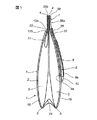
添付図面を参照すると、図1は、茶、カミツレ又は類似の草本製品のような浸出用物質を収容するフィルターバッグ1の全体を示す。フィルターバッグ1は、基本的には、内容物を収容するチャンバー2と、浸出中は収容チャンバー2を保持するとともにチャンバー2を手で取出すためのピックアップタグ6とを有し、チャンバー2及びタグ6は、糸状部分7により互いに接続される。
【0013】
収容チャンバー2は、ある分量の内容物のための2つの区画3を有し、2つの区画3は、上部接合部4及び底部接合部5において互いに接合される。
【0014】
2つの区画3は、互いに対向して重なり合い、V字形状の折り畳み基礎部14によって接合される。折り畳み基礎部14のV字の先端は、収容チャンバー2の内側に向いている。
【0015】
収容チャンバー2の外周には、糸状部分7が巻かれる。糸状部分7は、チャンバーの周囲に沿って延び、糸の一方の端部はピックアップタグ6に接続され、もう一方の端部は収容チャンバー2の上部15に接続される。
【0016】
糸状部分7は、糸状部分が取付けられる収容チャンバー2の周囲よりも長い。糸状部分7が有するその周囲を超過する過剰部分8は、糸状部分7の残りの部分に比べて緩い状態であり、残りの部分は、対照的に、収容チャンバー2の周囲に沿って緩みなく張られた状態である。過剰部分8は、浸出用物質を収容するチャンバー2の外側に寄せ集められ、1つ以上の第1巻きループ10の形状でピックアップタグ6に取付けられる。
【0017】
図1及び図2より明らかなように、ピックアップタグ6は、共有エッジ35の回りの回転によって互いに折り重ねられる2つのフラップ9a、9bを有し、共有エッジ35は、バッグ1の周囲に沿って巻かれた糸状部分7に平行である。糸7の過剰部分8は、これらのフラップ9aと9bとの間に保持される。
【0018】
ピックアップタグ6は、糸の過剰部分8に面するフラップ9a及び9bの面上に接着材の層を有することが好ましい。接着材は、適度な熱によって活性化可能な感熱接着材であり、それによりピックアップタグ6のフラップ9a及び9bは互いに貼り付けられた状態に保持され、そこにおいて糸状部分7の過剰部分8が規則的な形態で密に寄せ集められる。この保持は、ハンドリング中はパッケージ状態におけるいかなる変化も十分に防止できるものであり、小さな引張力をピックアップタグ6の外側の糸状部分7に加えることによって解除することができる。このことにより、第1ループ10が巻き戻されて、糸の過剰部分8がバッグ1及びピックアップタグ6から引出される。
【0019】
過剰部分8に隣接する糸状部分7の自由端36aをピックアップタグ6に固定することは、自由端36aを、ピックアップタグ6の複数のフラップ37の間を糸状部分7を横切る方向に通して、複数のフラップ37を封着することによって達成される。フラップ37はシールビード38により内面接続され、糸状部分の自由端36aはフラップ37から突き出てバッグ1の上部15に向かう。
【0020】
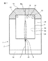
図2はまた、ピックアップタグ6をシール13によって収容チャンバー2の側壁16に接続する方法を示している。シール13は、感熱接着材の層を、ピックアップタグ6のフラップ9aの面の1つに使用することにより得られる。すなわちフラップ9a及び9bは、そのうちの1つが収容チャンバー2に面する。
【0021】
糸状部分7はまた、ピックアップタグ6に隣接する区画3とは分離された反対側の収容チャンバー2の区画3に収容される第2ループ11を有する。この第2ループ11は、区画3から突き出る分岐端12a、12bを有する。一方の分岐端12aは上部15に向かい、もう一方の分岐端12bは収容チャンバー2の底部14に向かう。上部15に向かう分岐端12aは、区画3の対向する複数の面の間に把持されて固定され、それらの面は、フィルター紙上の感熱接着材の層の熱による活性化によって互いに封着されて接合部4を形成する。区画の壁はこのフィルター紙から作製される。チャンバーの底部14に向かう分岐端12bは、ピックアップタグ6の固定側とは反対側の側壁16にある便宜的なスリット22において、その側壁16を通り抜けて延びる。
【0022】
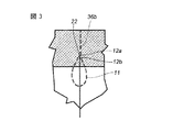
図3に示すように、第2ループ11の分岐端12a、12bは、糸状部分7を横切る方向に互いに対して移動するので、分岐端12a及び12bに接続された糸状部分7を引っ張ることにより、収容チャンバー2の上部15に皺が形成され、糸状部分7が上部15に確実に固定される。
【0023】
従って、上述のフィルターバッグ1において、糸状部分7の自由端36a及び36bは、2つの上部接合部4において収容チャンバー2の上部15に固定される。2つの上部接合部4はまた、収容チャンバー2が有する2つの別々の区画3を封着する。
【0024】
上述のフィルターバッグ1は、収容チャンバー2に吊着されたピックアップタグ6を手で取上げることによる通常の浸出を行うために使用される。しかし、ピックアップタグ6のフラップ9aと9bとの間に寄せ集められた糸の過剰部分8によって、バッグ1の上部15とピックアップタグ6との間の実際の距離は変更可能であるため、糸状部分7は、浸出が行われるカップ又はグラスの様々な大きさに対して、それぞれの場合について互換性のある長さになるように作製可能である。このことにより、ピックアップタグ6が偶発的に浸出液中に落下するリスクを回避できる。
【0025】
図4〜図13は、開示されたフィルターバッグ1を作製する連続したステップを含む操作の流れを示している。これらの図を参照すると、バッグの作製過程は、3つのみの包装材料を、予め定めた送り方向30に沿って、適切な配置にて互いに平行に送るステップを有することが先ず注目される。これらの材料は、感熱接着材の層を備えたウエブ状フィルター紙17と、ウエブ状フィルター紙17の長手方向にかつウエブ状フィルター紙17に対向して配置された木綿糸31と、ウエブ状タグ紙39とを有する。一組のタグ6は、ウエブ状タグ紙39から連続的に作製され、ウエブ状フィルター紙17に沿って予め定めた間隔にて配置される。
【0026】
図4は、送り方向30に送られるウエブ状タグ紙39をウエブ39の中間で先ず縦方向に折り、ウエブ39の折り曲げを容易にする線21をウエブ39上に形成する方法を示している。次に、ウエブ状タグ紙39は横断方向に切断され、同一平面上にあるフラップ9a、9bを備えたタグ6が形成される。フラップ9a、9bは、折線21によって互いに区切られる。
【0027】
図5に示すように、タグ6が切断されて糸31に対して配置された後の作製過程は、適当なフォーク手段によって、1つ以上の第1巻きループ10を糸31に形成するステップを有する。第1巻きループ10は、互いの上に連続して寄せ集められて、糸31からなる一種の輪を形成する。糸31の輪は、タグ6が有する開いたフラップ9a、9bのうちの1つのフラップ9aの前に配置される。
【0028】
次のステップにおいて、図6の左側に概略図示されるように、糸31の輪に接していないタグ6のフラップ9bは、折線21に沿って徐々に折られて、タグ6のフラップ9aに重ね合わされる。その後に、タグ6の2つのフラップ9a、9bは、感熱接着材の層の熱による活性化によって、互いに面するように貼り合わされる。
【0029】
この点において、図6の右側を参照すると、ウエブ状フィルター紙17(図6においては、タグが取付けられた状態で糸31の上に示されている)は、紙17にスリット22を形成するように切られる。
【0030】
糸31は、図7の左側のスリット22を通って、ウエブ状フィルター紙17上を延び、第2ループ11を形成するように動かされる。以降のステップが行われる間は、ループ11は、フィルター紙上に好都合に局在して熱により再活性化する感熱接着材の層を用いたシールによって、フィルター紙にしっかりと固定される。
【0031】
同じ操作が行われる間に、タグ6の下方の糸の輪を含むように、フィルター紙をタグ6に取付けるシールもまた形成される。
【0032】
次にバッグの作製過程において、図7の右側に示されるように、ウエブ状フィルター紙17を自らに重なるように折るステップが行われる。それにより、初めは互いに反対側にあったエッジ18が重ね合わされて、チューブ状フィルター紙34が徐々に形成される。チューブ34の内部の凹んだ領域は、ループ11を収容する。チューブ34が完全に形成される前に、ある分量の2つの浸出用物質19がウエブ17上に連続的に乗せられる。
【0033】
図8の左側及び中央に概略図示されたエッジ18が完全に重ね合わされると、チューブ34の長手方向のエッジ18を、フィルター紙上の感熱接着材の層を熱で活性化させることによるシールによって互いに封着するステップが行われる。図8の右側に示されるように、次のステップが行われる間にチューブ34は別々の区画3に分割され、区画3の各々は、ある分量の浸出用物質19を有する。区画3は、封着された複数の対の横断方向接合部20により、タグ6の上流側及び下流側にそれぞれ形成される。より詳細には、これらの接合部は、区画3を接合する上部接合部4及び底部接合部5を形成し、また糸31をフィルターバッグ1の収容チャンバー2に固定する。
【0034】
図9に概略図示されるように、バッグ作製過程の次のステップにおいて、隣接する2つの区画3を有する領域が切断され、チューブ34から分離される。
【0035】
図10に概略図示されるステップにおいては、隣接する2つの区画3が互いに折り重ねられると同時に、収容チャンバー2の基礎部14に「逆V字」形状が形成される。
【0036】
図12に示されるように、上部が封着されると、区画3が互いに取付けられて、収容チャンバー2が有する単一部材の上部15を形成する。図13に示される次のステップにおいては、フィルターバッグ1の上部15の角23が切除される。
【0037】
既述された本発明は、発明思想の範囲から逸脱することなく、修正や変更を行うことができる。さらに、本発明の詳細は全て、技術的に等価な要素に置換可能である。
【図面の簡単な説明】
【図1】本発明に従って作製されたフィルターバッグの側面の拡大図である。
【図2】図1に示されたフィルターバッグの前面図である。
【図3】図2の反対側からみた、図1に示されたフィルターバッグの詳細図である。
【図4】図1〜図3に示されたフィルターバッグの作製方法を具体的に表す連続するステップの概要図である。
【図5】図1〜図3に示されたフィルターバッグの作製方法を具体的に表す連続するステップの概要図である。
【図6】図1〜図3に示されたフィルターバッグの作製方法を具体的に表す連続するステップの概要図である。
【図7】図1〜図3に示されたフィルターバッグの作製方法を具体的に表す連続するステップの概要図である。
【図8】図1〜図3に示されたフィルターバッグの作製方法を具体的に表す連続するステップの概要図である。
【図9】図1〜図3に示されたフィルターバッグの作製方法を具体的に表す連続するステップの概要図である。
【図10】図1〜図3に示されたフィルターバッグの作製方法を具体的に表す連続するステップの概要図である。
【図11】図1〜図3に示されたフィルターバッグの作製方法を具体的に表す連続するステップの概要図である。
【図12】図1〜図3に示されたフィルターバッグの作製方法を具体的に表す連続するステップの概要図である。
【図13】図1〜図3に示されたフィルターバッグの作製方法を具体的に表す連続するステップの概要図である。
【符号の説明】
1…フィルターバッグ
2…チャンバー
3…区画
6…タグ
7…糸
9a、9b…フラップ
17…ウエブ
34…チューブ[0001]
BACKGROUND OF THE INVENTION
The present invention relates to automatic packaging in which a leaching material, such as tea, chamomile or similar herbaceous product, is enclosed in a paper filter bag configured to be immersed in a liquid for leaching. The present invention particularly relates to a filter bag having a special structure and a method for producing the same.
[0002]
[Prior art]
In recent market research, a new paper filter bag (known as a two-lobed filter bag) with a containment chamber with two compartments made by heat sealing. ) Is attracting attention. The filter bag is manufactured by folding filter paper and sealing the bent portion. This uses a method of heating and activating the layer of heat-sensitive adhesive applied to the web-like paper during one of the production steps.
[0003]
However, a filter bag made from heat-sealable filter paper using a conventional method is a filter bag of the same size and shape in which a chamber holding a certain amount of leaching product is formed only by bending. Heavy compared to
[0004]
[Problems to be solved by the invention]
Since the cost of paper is proportional to its weight, a heavy filter bag made from heat-sealable filter paper is expensive compared to a filter bag made using only folding if the other conditions are the same. It is. Since the overall weight of the filter bag is light, even if the weight increase is only a few grams, the effect on the cost of the entire filter bag is significant. In order to make a filter bag made from heat-sealed paper economically compete with a filter bag made only from folding, a filter bag made from heat-sealed paper is better than a filter bag made only from folding. Generally, the size is generally small.
[0005]
If a filter bag made from heat-sealed paper is made with a pickup tag connected to a thread wound to fit snugly around the filter bag, reducing the size of the filter bag This means that the effective length of the yarn is shortened. When leaching in certain teapots or especially in tall cups or glasses, with the yarn lengths mentioned above, the tag accidentally slips off the edge of the brewing vessel during leaching and falls into the leachate. May not be sufficient to prevent it. Obviously, dropping the tag into the leachate is accompanied by at least one of hygiene problems and pick-up tag removal problems.
[0006]
Furthermore, the steps of making a filter bag made from heat-sealed paper by known methods include using a small amount of adhesive (usually Mylar®) on the yarn and filter bag, thereby These components can be held in a compact structure, and the tag can be prevented from wobbling away from the bag.
[0007]
The cost of the material used as an amount of adhesive disadvantageously increases the overall cost of the filter bag. There is also the cost of packaging machines with complex structures that require equipment designed for bag adhesives.
[0008]
The main object of the present invention is to overcome the above-mentioned disadvantages by providing a bag made from heat-sealed paper having a thread-like length that is independent of the length that fits around the filter bag. is there.
[0009]
Another object of the present invention is to provide a more economical filter bag by not using an adhesive (Mylar) and to make the device for making the bag simpler and less expensive.
[0010]
[Means for Solving the Problems]
According to the present invention, these and other objects are leached in a liquid having a containment chamber with at least one compartment sealed by a top joint and a bottom joint for holding a quantity of material. This is achieved by a filter bag containing a substance for the purpose. The filter bag has a pickup tag and a thread-like portion for lifting the filter bag. The thread-like portion extends along the circumference of the accommodation chamber and is wound around the outside of the accommodation chamber. One end of the yarn is connected to the pickup tag, and the other end is connected to the upper portion of the accommodation chamber. The present invention is characterized in that the thread-like part is longer than the circumference of the storage chamber to which the thread-like part is attached, and the excess part of the thread-like part exceeding the circumference is gathered outside the chamber containing the leaching substance. And The present invention also relates to a method for producing the filter bag.
[0011]
The technical features of the present invention are set forth in the appended claims in accordance with the above-mentioned objects. The advantages of the present invention will become more apparent from the following description with reference to the accompanying drawings. These drawings exemplify preferred embodiments of the present invention and do not limit the scope of the idea of the present invention.
[0012]
DETAILED DESCRIPTION OF THE INVENTION
Referring to the accompanying drawings, FIG. 1 shows the
[0013]
The
[0014]
The two
[0015]
A thread-
[0016]
The thread-
[0017]
As is clear from FIGS. 1 and 2, the
[0018]
The
[0019]
Fixing the
[0020]
FIG. 2 also shows how the
[0021]
The thread-
[0022]
As shown in FIG. 3, the branch ends 12 a and 12 b of the
[0023]
Therefore, in the above-described
[0024]
The
[0025]
4 to 13 show the operational flow including successive steps to make the disclosed
[0026]
FIG. 4 shows a method in which a web-
[0027]
As shown in FIG. 5, the manufacturing process after the
[0028]
In the next step, as schematically shown on the left side of FIG. 6, the
[0029]
In this regard, referring to the right side of FIG. 6, the web-shaped filter paper 17 (shown on the
[0030]
The
[0031]
A seal is also formed that attaches the filter paper to the
[0032]
Next, in the bag manufacturing process, as shown on the right side of FIG. 7, a step of folding the web-shaped
[0033]
When the
[0034]
As schematically illustrated in FIG. 9, in the next step of the bag making process, the region having two
[0035]
In the step schematically illustrated in FIG. 10, two
[0036]
As shown in FIG. 12, when the top is sealed, the
[0037]
The above-described present invention can be modified or changed without departing from the scope of the inventive idea. Moreover, all details of the invention may be replaced by technically equivalent elements.
[Brief description of the drawings]
FIG. 1 is an enlarged side view of a filter bag made in accordance with the present invention.
FIG. 2 is a front view of the filter bag shown in FIG.
3 is a detailed view of the filter bag shown in FIG. 1, as viewed from the opposite side of FIG.
FIG. 4 is a schematic diagram of successive steps specifically illustrating a method of making the filter bag shown in FIGS.
FIG. 5 is a schematic diagram of successive steps specifically illustrating a method of making the filter bag shown in FIGS.
6 is a schematic diagram of successive steps specifically illustrating a method of making the filter bag shown in FIGS. 1-3. FIG.
7 is a schematic diagram of successive steps specifically illustrating a method of making the filter bag shown in FIGS. 1-3. FIG.
FIG. 8 is a schematic diagram of successive steps specifically illustrating a method of making the filter bag shown in FIGS.
FIG. 9 is a schematic diagram of successive steps specifically illustrating a method of making the filter bag shown in FIGS.
FIG. 10 is a schematic diagram of successive steps specifically illustrating a method of making the filter bag shown in FIGS.
FIG. 11 is a schematic diagram of successive steps specifically illustrating a method of making the filter bag shown in FIGS.
12 is a schematic diagram of successive steps specifically illustrating a method of making the filter bag shown in FIGS. 1-3. FIG.
FIG. 13 is a schematic diagram of successive steps specifically illustrating a method of making the filter bag shown in FIGS.
[Explanation of symbols]
DESCRIPTION OF
Claims (29)
前記糸状部分(7)は、該糸状部分(7)が取付けられる前記収容チャンバー(2)の前記周囲よりも長く、前記糸状部分(7)の前記周囲を超過する過剰部分(8)は、浸出するための前記物質の前記収容チャンバー(2)の外側に寄せ集められ、
前記糸状部分(7)は、前記収容チャンバー(2)の前記区画(3)の1つに収容された第2ループ(11)を有し、該第2ループ(11)は、前記区画(3)から突き出る複数の端部(12a、12b)を有し、該複数の端部の一方の端部(12a)は前記上部接合部(4)に向かい、前記複数の端部のもう一方の端部(12b)は、前記第2ループ(11)を収容する前記区画(3)の側壁(16)を通ることを特徴とするフィルターバッグ。A filter bag (1) containing a substance for leaching in a liquid, at least one sealed by a top joint (4) and a bottom joint (5) for holding a quantity of said substance A storage chamber (2) having two compartments (3), a pickup tag (6) for lifting the filter bag (1), and wound around the outside of the storage chamber (2). A thread-like part (7) extending along the periphery, one end of the thread-like part is connected to the pickup tag (6), and the other end is an upper part (15) of the storage chamber (2). In the filter bag (1) connected to
The thread-like part (7) is longer than the circumference of the receiving chamber (2) to which the thread-like part (7) is attached, and the excess part (8) exceeding the circumference of the thread-like part (7) brought together outside of the housing chamber (2) of the substance for,
The thread-like portion (7) has a second loop (11) accommodated in one of the compartments (3) of the accommodation chamber (2), and the second loop (11) comprises the compartment (3). A plurality of ends (12a, 12b) projecting from one end (12a) of the plurality of ends toward the upper joint (4) and the other end of the plurality of ends. The part (12b) passes through the side wall (16) of the compartment (3) that houses the second loop (11) .
前記糸状部分(7)の前記過剰部分(8)が、前記ピックアップタグ(6)の前記フラップ(9a、9b)の間に保持されることを特徴とするフィルターバッグ。The filter bag (1) according to claim 6, wherein the pickup tag (6) has at least two flaps (9a, 9b) which can be folded against each other.
The filter bag, wherein the excess portion (8) of the thread-like portion (7) is held between the flaps (9a, 9b) of the pickup tag (6).
ウエブ状フィルター紙(17)と、該ウエブ状フィルター紙(17)の長手方向にかつ該ウエブ状フィルター紙(17)に対向して配置された木綿製の糸(31)と、前記ウエブ状フィルター紙(17)に沿って予め定めた間隔(32)にて連続的に配置された複数のピックアップタグ(6)とを、互いに平行にかつ予め定めた方向(30)に送るステップと、
前記糸(31)に、前記ピックアップタグ(6)の前記間隔(32)に対応する間隔(33)だけ離れた複数の第1巻きループ(10)を連続的に形成するステップと、
前記第1巻きループ(10)を前記ピックアップタグ(6)に接続し、該ピックアップタグ(6)を前記ウエブ状フィルター紙(17)に接続するステップと、
初めは互いに反対側にあった前記ウエブ状フィルター紙(17)のエッジ(18)が重ね合わされて、チューブ状フィルター紙(34)が徐々に形成されるように、前記ウエブ状フィルター紙(17)を自らに重なるように折るステップと、
前記チューブ状フィルター紙(34)が完全に形成される前に、ある分量の浸出用の複数の前記物質(19)を前記ウエブ状フィルター紙(17)上に連続的に乗せるステップと、
前記チューブ状フィルター紙(34)の長手方向の前記エッジ(18)を互いに接合するステップと、
前記ピックアップタグ(6)の上流側及び下流側で前記チューブ状フィルター紙(34)に、少なくとも1つのある分量の浸出用の前記物質(19)を収容する複数の封着された収容チャンバー(2)を連続して画定するように構成された複数の対の横断方向接合部(20)を形成するステップと、
前記複数の対の横断方向接合部(20)の間の前記糸状部分を前記チューブ状フィルター紙(34)に固定するステップと、
を有することを特徴とするフィルターバッグの作製方法。 In a method of making a filter bag (1) containing a substance for leaching in a liquid,
A web-like filter paper (17), a cotton thread (31) arranged in the longitudinal direction of the web-like filter paper (17) and facing the web-like filter paper (17), and the web-like filter Sending a plurality of pickup tags (6) arranged continuously at a predetermined interval (32) along the paper (17) in parallel to each other and in a predetermined direction (30);
Continuously forming a plurality of first winding loops (10) on the yarn (31) separated by an interval (33) corresponding to the interval (32) of the pickup tag (6);
Connecting the first winding loop (10) to the pickup tag (6) and connecting the pickup tag (6) to the web filter paper (17);
The web-shaped filter paper (17) is formed so that the edges (18) of the web-shaped filter paper (17) that are initially opposite to each other are overlapped to form a tubular filter paper (34) gradually. Fold the steps so that they overlap with each other,
Before the tube-shaped filter paper (34) is completely formed, placing a quantity of the brewing substances (19) continuously on the web-shaped filter paper (17);
Joining the longitudinal edges (18) of the tubular filter paper (34) together;
A plurality of sealed storage chambers (2) storing at least one brewing substance (19) in the tubular filter paper (34) upstream and downstream of the pickup tag (6). Forming a plurality of pairs of transverse joints (20) configured to sequentially define
Securing the thread-like portion between the plurality of pairs of transverse joints (20) to the tubular filter paper (34);
A method for producing a filter bag, comprising:
前記チューブ状フィルター紙(34)の前記長手方向のエッジ(18)が、前記ウエブ状フィルター紙(17)上の前記感熱接着材の層の熱による活性化によって接合されることを特徴とする作製方法。 The method for producing a filter bag according to claim 15, wherein the web-shaped filter paper (17) has a layer of heat-sensitive adhesive.
Fabrication characterized in that the longitudinal edges (18) of the tubular filter paper (34) are joined by heat activation of the layer of heat sensitive adhesive on the web filter paper (17). Method.
前記複数の対の横断方向接合部(20)が、前記ウエブ状フィルター紙(17)上の前記感熱接着材の層の熱による活性化によって形成されることを特徴とする作製方法。 The method for producing a filter bag according to claim 15 or 16, wherein the web-shaped filter paper (17) has a layer of a heat-sensitive adhesive.
The method according to claim 1, wherein the plurality of pairs of transverse joints (20) are formed by heat activation of the heat-sensitive adhesive layer on the web filter paper (17) .
前記複数の対の横断方向接合部(20)の間の前記糸状部分を前記チューブ状フィルター紙(34)に固定する前記ステップが、前記感熱接着材の層の熱による活性化によって行われることを特徴とする作製方法。 The method for producing a filter bag according to any one of claims 15 to 17, wherein the web-shaped filter paper (17) has a layer of a heat-sensitive adhesive.
The step of fixing the thread-like portion between the plurality of pairs of transverse joints (20) to the tubular filter paper (34) is performed by thermal activation of the layer of heat-sensitive adhesive ; A featured manufacturing method.
前記第1巻きループ(10)は、前記ピックアップタグ(6)の第1フラップ(9a)において前記ピックアップタグ(6)に取付けられ、前記作製方法は、前記ピックアップタグ(6)の第2フラップ(9b)が前記第1巻きループ(10)に重なりかつ前記ピックアップタグ(6)の前記第1フラップ(9a)に接続されるように、前記第2フラップ(9a)を配置する折り重ねステップを含むことを特徴とする作製方法。 The method for producing a filter bag according to any one of claims 15 to 18, wherein the pickup tag (6) has two flaps (9a, 9b) that can be folded on each other .
The first winding loop (10) is attached to the pickup tag (6) at the first flap (9a) of the pickup tag (6), and the manufacturing method includes the second flap (10) of the pickup tag (6). 9b) includes a folding step of placing the second flap (9a) so that it overlaps the first winding loop (10) and is connected to the first flap (9a) of the pickup tag (6) A manufacturing method characterized by the above.
複数の前記フラップ(9a、9b)が前記感熱接着材の熱による活性化によって互いに接続されることを特徴とする作製方法。 The method for producing a filter bag according to claim 19, wherein the pickup tag (6) has a layer of heat-sensitive adhesive.
A manufacturing method , wherein a plurality of the flaps (9a, 9b) are connected to each other by heat activation of the heat-sensitive adhesive .
該スリット(22)に前記糸(31)を通して、前記ウエブ状フィルター紙(17)における前記糸(31)が接する側とは反対側から突き出る第2ループ(11)を形成するステップと、
をさらに有することを特徴とする請求項15〜22のいずれか1項に記載の作製方法。 Cutting the web filter paper (17) at a predetermined distance from the pickup tag (6) to form a slit (22);
Passing the thread (31) through the slit (22) to form a second loop (11) protruding from the opposite side of the web-shaped filter paper (17) to which the thread (31) contacts;
The manufacturing method according to claim 15, further comprising:
前記区画(3)が互いに重なり合うように該区画(3)を折るステップであって、前記糸(31)が前記収容チャンバー(2)の周囲全体に巻かれ、それにより前記ピックアップタグ(6)と該ピックアップタグ(6)に接続された第1巻きループ(10)とが前記収容チャンバー(2)全体の外面に配置されるステップと、
チューブ状の複数の前記区画(3)が有する複数の前記上部接合部(4)を接合して、前記フィルターバッグ(1)の収容チャンバー(2)の1つの上部(15)を形成するステップと、
をさらに有することを特徴とする作製方法。 27. The method for producing a filter bag according to any one of claims 15 to 26, wherein the storage chamber (2) is divided into two adjacent compartments (3).
Folding the compartment (3) so that the compartment (3) overlaps each other, wherein the thread (31) is wound around the entire circumference of the containing chamber (2), whereby the pickup tag (6) and A first winding loop (10) connected to the pickup tag (6) is disposed on the outer surface of the entire storage chamber (2);
Joining the plurality of upper joint portions (4) of the plurality of tubular sections (3) to form one upper portion (15) of the storage chamber (2) of the filter bag (1); ,
A manufacturing method characterized by further comprising:
Applications Claiming Priority (2)
| Application Number | Priority Date | Filing Date | Title |
|---|---|---|---|
| IT2002BO000013A ITBO20020013A1 (en) | 2002-01-11 | 2002-01-11 | FILTER BAG FOR CONTAINMENT OF AN INFUSION SUBSTANCE WITH ACCUMULATION OF WIRE ASSOCIATED WITH THE TAKING LABEL AND RELAY FORMING METHOD |
| IT2002A000013 | 2002-02-12 |
Publications (3)
| Publication Number | Publication Date |
|---|---|
| JP2003210331A JP2003210331A (en) | 2003-07-29 |
| JP2003210331A5 JP2003210331A5 (en) | 2006-02-23 |
| JP4057431B2 true JP4057431B2 (en) | 2008-03-05 |
Family
ID=11439790
Family Applications (1)
| Application Number | Title | Priority Date | Filing Date |
|---|---|---|---|
| JP2003004742A Expired - Fee Related JP4057431B2 (en) | 2002-01-11 | 2003-01-10 | Filter bag and manufacturing method thereof |
Country Status (13)
| Country | Link |
|---|---|
| US (2) | US20030131565A1 (en) |
| EP (1) | EP1327589B1 (en) |
| JP (1) | JP4057431B2 (en) |
| KR (1) | KR20030061299A (en) |
| CN (1) | CN1301887C (en) |
| AR (1) | AR038284A1 (en) |
| AT (1) | ATE320985T1 (en) |
| CA (1) | CA2415805A1 (en) |
| DE (1) | DE60210041T2 (en) |
| ES (1) | ES2260408T3 (en) |
| IT (1) | ITBO20020013A1 (en) |
| TW (1) | TWI250115B (en) |
| ZA (1) | ZA200210237B (en) |
Families Citing this family (9)
| Publication number | Priority date | Publication date | Assignee | Title |
|---|---|---|---|---|
| AU2002226271A1 (en) * | 2002-01-24 | 2003-09-04 | Radek Vana | Method for production of plant extracts |
| ITBO20020477A1 (en) | 2002-07-23 | 2004-01-23 | Tecnomeccanica Srl | APPARATUS FOR PREPARING AND FEEDING MATERIALS FOR PACKAGING A FILTER BAG FOR INFUSION SUBSTANCES. |
| ITBO20060094A1 (en) | 2006-02-10 | 2007-08-11 | Tecnomeccanica Srl | METHOD AND A HIGH SPEED PACKAGING LINE OF ENVELOPES FILTER CONTAINING AN INFUSION SUBSTANCE |
| US20080078770A1 (en) * | 2006-10-02 | 2008-04-03 | Eric Thomas | Insulated package insert apparatus and method |
| US20080250689A1 (en) * | 2007-04-13 | 2008-10-16 | Stacey Cohen | Seeded Hangtag |
| EP2590864B1 (en) * | 2010-07-07 | 2014-03-19 | Unilever PLC | Process and apparatus for producing packets |
| ITBO20120706A1 (en) * | 2012-12-21 | 2014-06-22 | Ima Ind Srl | MACHINE FOR FORMING BAGS WITH INFUSION PRODUCTS |
| USD952286S1 (en) | 2021-01-07 | 2022-05-24 | Veriant LLC | Tea bag |
| USD961404S1 (en) | 2021-01-07 | 2022-08-23 | Veriant LLC | Double tea bag |
Family Cites Families (17)
| Publication number | Priority date | Publication date | Assignee | Title |
|---|---|---|---|---|
| US2468464A (en) * | 1946-02-07 | 1949-04-26 | Ivers Lee Co | Infusion package |
| US2490057A (en) * | 1946-05-25 | 1949-12-06 | Nat Urn Bag Co Inc | Method of making an infusion package with a nontangling handle and tag |
| US2852389A (en) * | 1954-08-06 | 1958-09-16 | Bartelt Engineering Co | Infusion package |
| US2869718A (en) * | 1956-09-14 | 1959-01-20 | Pneumatic Scale Corp | Infusion bag |
| AT239134B (en) * | 1961-07-11 | 1965-03-25 | Guy John Olof Welin-Berger | A bag made from a woven or woven thread |
| CH615124A5 (en) * | 1978-01-11 | 1980-01-15 | Sig Schweiz Industrieges | |
| CH638740A5 (en) * | 1979-06-26 | 1983-10-14 | Sig Schweiz Industrieges | INFUSION BAG AND METHOD FOR THE PRODUCTION THEREOF. |
| IT1187308B (en) * | 1985-02-08 | 1987-12-23 | Cestind Centro Studi Ind | DISPOSABLE BAG-FILTER FOR INFUSION PRODUCTS AND METHOD TO PRODUCE IT |
| GB9026123D0 (en) * | 1990-11-30 | 1991-01-16 | Unilever Plc | Tagged articles and method and apparatus for their production |
| GB9219657D0 (en) * | 1992-09-17 | 1992-10-28 | Unilever Plc | Tagged articles |
| IT1279697B1 (en) * | 1995-12-07 | 1997-12-16 | Tecnomeccanica Srl | MACHINE FOR PACKAGING ASSEMBLIES FOR INFUSION IN A LIQUID IN WHICH AN INFUSIBLE PRODUCT IS CONTAINED IN A FILTER BAG IN |
| EP0806352B1 (en) * | 1996-05-07 | 2001-11-07 | Teepack Spezialmaschinen Gmbh & Co. Kg | Twin-compartment infusion bag, especially for tea, and process for its manufactue |
| GB9722490D0 (en) * | 1997-10-25 | 1997-12-24 | Cambridge Consultants | Improvements in and relating to tags and their attachment to products |
| IT1299331B1 (en) * | 1998-01-30 | 2000-03-16 | Ima Spa | BAG - BI-LOBO TYPE FILTER FOR INFUSION PRODUCTS. |
| PT1002741E (en) * | 1998-06-10 | 2001-12-28 | Teepack Spezialmaschinen | INFLATABLE BAG OF A COMPARTMENT IN PARTICULAR FOR CHA AND PROCESS FOR ITS MANUFACTURE |
| IT1304448B1 (en) * | 1998-12-24 | 2001-03-19 | Ima Spa | BAG - BILOBO FILTER FOR INFUSION PRODUCTS. |
| JP2002211641A (en) * | 2001-01-15 | 2002-07-31 | Fuso Sangyo Kk | Hanging member, wrapping material, and packaging body |
-
2002
- 2002-01-11 IT IT2002BO000013A patent/ITBO20020013A1/en unknown
- 2002-12-09 TW TW091135583A patent/TWI250115B/en not_active IP Right Cessation
- 2002-12-17 ES ES02425781T patent/ES2260408T3/en not_active Expired - Lifetime
- 2002-12-17 EP EP02425781A patent/EP1327589B1/en not_active Expired - Lifetime
- 2002-12-17 AT AT02425781T patent/ATE320985T1/en not_active IP Right Cessation
- 2002-12-17 DE DE60210041T patent/DE60210041T2/en not_active Expired - Lifetime
- 2002-12-18 ZA ZA200210237A patent/ZA200210237B/en unknown
- 2002-12-26 KR KR1020020083889A patent/KR20030061299A/en not_active Application Discontinuation
-
2003
- 2003-01-08 CA CA002415805A patent/CA2415805A1/en not_active Abandoned
- 2003-01-09 AR ARP030100054A patent/AR038284A1/en active IP Right Grant
- 2003-01-10 CN CNB031015387A patent/CN1301887C/en not_active Expired - Fee Related
- 2003-01-10 JP JP2003004742A patent/JP4057431B2/en not_active Expired - Fee Related
- 2003-01-13 US US10/341,570 patent/US20030131565A1/en not_active Abandoned
-
2004
- 2004-02-18 US US10/780,958 patent/US7021025B2/en not_active Expired - Fee Related
Also Published As
| Publication number | Publication date |
|---|---|
| CN1301887C (en) | 2007-02-28 |
| TW200301747A (en) | 2003-07-16 |
| ES2260408T3 (en) | 2006-11-01 |
| US20040161497A1 (en) | 2004-08-19 |
| JP2003210331A (en) | 2003-07-29 |
| ITBO20020013A1 (en) | 2003-07-11 |
| EP1327589A3 (en) | 2004-02-04 |
| US7021025B2 (en) | 2006-04-04 |
| DE60210041D1 (en) | 2006-05-11 |
| US20030131565A1 (en) | 2003-07-17 |
| ITBO20020013A0 (en) | 2002-01-11 |
| ATE320985T1 (en) | 2006-04-15 |
| AR038284A1 (en) | 2005-01-12 |
| EP1327589A2 (en) | 2003-07-16 |
| CA2415805A1 (en) | 2003-07-11 |
| KR20030061299A (en) | 2003-07-18 |
| DE60210041T2 (en) | 2006-10-12 |
| TWI250115B (en) | 2006-03-01 |
| EP1327589B1 (en) | 2006-03-22 |
| CN1432519A (en) | 2003-07-30 |
| ZA200210237B (en) | 2003-08-21 |
Similar Documents
| Publication | Publication Date | Title |
|---|---|---|
| JP4134062B2 (en) | Pack sheet packaging and pack sheet packaging method | |
| WO2003055760A1 (en) | Self-standing packaging bag, packaging body, web roll, and manufacturing method therefor | |
| FR2702743A1 (en) | Device combining a disposable towel and a packaging for fast food, and continuous manufacturing method. | |
| JP4057431B2 (en) | Filter bag and manufacturing method thereof | |
| US4415597A (en) | Filter-bag for infusion products | |
| JPH0815895B2 (en) | Continuous automatic production equipment for dual-purpose filter bags enclosing leach products for sprinkling | |
| US6733804B1 (en) | Multi-chambered infusion bag, especially for tea | |
| US2852389A (en) | Infusion package | |
| JPH0431275A (en) | Package and production thereof | |
| JP5026165B2 (en) | Roll paper packaging | |
| JP4882188B2 (en) | Dripper | |
| JP3903389B2 (en) | Packing bag | |
| JP2767213B2 (en) | Package | |
| JP2004195198A (en) | Dripper | |
| JP2019137463A (en) | Packaging member with paste and overlapping bundle body | |
| JPH0630004U (en) | Strainer pack | |
| JP4061176B2 (en) | Dripper | |
| JP3683816B2 (en) | Filter bag with hanging strings | |
| JP3060171B2 (en) | Commodity packaging bag with header and method of manufacturing the same | |
| JP2003009788A (en) | Method for packaging food such as tapered laver- wrapped sushi and packaging material | |
| JP4170595B2 (en) | Dripper | |
| JP4363930B2 (en) | Thin plastic packaging bag with handle | |
| JP2000152875A (en) | Filtering bag provided with hanging thread, manufacture thereof, and manufacturing device thereof | |
| JP2694628B2 (en) | Integrated packaging paper bag | |
| JP2903477B2 (en) | Cartridges made of paper, such as coffee |
Legal Events
| Date | Code | Title | Description |
|---|---|---|---|
| A521 | Request for written amendment filed |
Free format text: JAPANESE INTERMEDIATE CODE: A523 Effective date: 20060105 |
|
| A621 | Written request for application examination |
Free format text: JAPANESE INTERMEDIATE CODE: A621 Effective date: 20060105 |
|
| A131 | Notification of reasons for refusal |
Free format text: JAPANESE INTERMEDIATE CODE: A131 Effective date: 20070710 |
|
| A521 | Request for written amendment filed |
Free format text: JAPANESE INTERMEDIATE CODE: A523 Effective date: 20071009 |
|
| TRDD | Decision of grant or rejection written | ||
| A01 | Written decision to grant a patent or to grant a registration (utility model) |
Free format text: JAPANESE INTERMEDIATE CODE: A01 Effective date: 20071113 |
|
| A61 | First payment of annual fees (during grant procedure) |
Free format text: JAPANESE INTERMEDIATE CODE: A61 Effective date: 20071213 |
|
| R150 | Certificate of patent or registration of utility model |
Free format text: JAPANESE INTERMEDIATE CODE: R150 |
|
| FPAY | Renewal fee payment (event date is renewal date of database) |
Free format text: PAYMENT UNTIL: 20101221 Year of fee payment: 3 |
|
| LAPS | Cancellation because of no payment of annual fees |