JP4055314B2 - Cooker - Google Patents
Cooker Download PDFInfo
- Publication number
- JP4055314B2 JP4055314B2 JP34982899A JP34982899A JP4055314B2 JP 4055314 B2 JP4055314 B2 JP 4055314B2 JP 34982899 A JP34982899 A JP 34982899A JP 34982899 A JP34982899 A JP 34982899A JP 4055314 B2 JP4055314 B2 JP 4055314B2
- Authority
- JP
- Japan
- Prior art keywords
- suction
- duct
- intake
- main body
- opening
- Prior art date
- Legal status (The legal status is an assumption and is not a legal conclusion. Google has not performed a legal analysis and makes no representation as to the accuracy of the status listed.)
- Expired - Fee Related
Links
Images


Landscapes
- Baking, Grill, Roasting (AREA)
Description
【0001】
【発明の属する技術分野】
本発明は、焼肉料理等をする時に発生する油煙を低減する加熱調理器に関するものである。
【0002】
【従来の技術】
従来の加熱調理器は図6に示すような構成になっていた。1は被加熱器具である調理プレート、2は調理プレート1を加熱するための加熱手段、3は調理プレート1の略中央に設けられた吸込み部、4は調理プレート1の周壁上に設けられた吹出し部である。5は送風手段で、伝達手段6を介してモーター7により駆動される。8は吸込み部3の下部に配置された油煙除去手段である。9は本体外郭ケースで遮熱板10とで空気流路11を形成している。以上の構成で、加熱手段2より調理プレート1を加熱し、肉、野菜等の食材を調理プレート1の上に載せて焼く。食材が焼けてくると調理プレート1の表面から油煙が発生し、その油煙は調理プレート1の熱でできる上昇気流にのって室内に拡散していく。この時、モーター7に通電すると伝達手段6により送風手段5から風が発生し、空気流路11を通り、吹出し部4から吸込み部3へ向けて直線的に空気が吹出される。吹出された空気は、調理プレート1の上で発生する油煙を調理プレート1の中央に向けて押し流し、吸込み部3より油煙と共に吸引され、吸引された油煙は、油煙除去手段8により除去される。
【0003】
【発明が解決しようとする課題】
しかしながら上記のような従来構成では、吸込み部3が調理プレート1の中央にあり、一番使用頻度の高い場所で調理ができないので使用勝手が悪く。また、吹出し部4が本体外郭ケース9と一体になって全周取囲んでいるので、本体が大きくなると共に、被加熱手段に鍋等を用いた場合、除煙機能が必要でないにもかかわらず本体には吹出し部4が具備された状態となり、鍋加熱に対して違和感のある構成である等の課題があった。
【0004】
本発明はこのような従来の課題を解決するものであり、焼肉料理等をする時に発生する油煙を低減する加熱調理器において、調理プレート面の使用性を向上させ、また、製品本体を小型化にし、さらに鍋等の使用においても違和感の無い構成を提供することを目的とする。
【0005】
【課題を解決するための手段】
上記課題を解決するために本発明は、本体上部に設けられた加熱手段と、本体外郭に設けられた吸気口及び排気口と、前記吸気口および前記排気口に設けた回転自在な開閉蓋と、被加熱器具の両端に設けられたダクトと、前記開閉蓋と対向した前記ダクトの部分に設けた突出部と、前記ダクトに連通穴からなる吸込み部と吹出し部とを設け、被加熱器具を本体に載置した際には、前記吸気口と前記吸込み部、前記排気口と前記吹出し部とが連結し、前記吸込み部から送風手段の吸込み側までの吸気側経路内には油除去手段を有し、前記吸込み部の開口部と前記吹出し部の開口部とは略対向する位置とし、前記吹出し部から前記吸込み部へ空気の流れを形成し、かつ、前記突出部が前記開閉蓋の回転軸から離れた部分に当接し、前記開閉蓋を開く加熱調理器とすることで、予め本体の吸気口および排気口に設けられた蓋を取り外して被加熱器具を置く必要が無いので、使い勝手がさらに向上する。
【0006】
【発明の実施の形態】
本発明の請求項1記載の発明は、本体上部に設けられた加熱手段と、本体外郭に設けられた吸気口及び排気口と、前記吸気口および前記排気口に設けた回転自在な開閉蓋と、被加熱器具の両端に設けられたダクトと、前記開閉蓋と対向した前記ダクトの部分に設けた突出部と、前記ダクトに連通穴からなる吸込み部と吹出し部とを設け、被加熱器具を本体に載置した際には、前記吸気口と前記吸込み部、前記排気口と前記吹出し部とが連結し、前記吸込み部から送風手段の吸込み側までの吸気側経路内には油除去手段を有し、前記吸込み部の開口部と前記吹出し部の開口部とは略対向する位置とし、前記吹出し部から前記吸込み部へ空気の流れを形成し、かつ、前記突出部が前記開閉蓋の回転軸から離れた部分に当接し、前記開閉蓋を開く加熱調理器であり、予め本体の吸気口および排気口に設けられた蓋を取り外して被加熱器具を置く必要が無いので、使い勝手がさらに向上する。
【0007】
本発明の請求項2記載の発明は、回転自在な開閉蓋を本体の吸気口および排気口に設け、開閉蓋とそれに対向したダクトの部分の少なくともどちらか一方に磁石をもう一方には磁性金属を具備し、被加熱器具を本体に設置した際に磁石と磁性金属とが開閉蓋の回転軸から離れた部分で吸着し、開閉蓋を開くので、上記同様使い勝手が向上するとともにより確実な開閉機構を提供することができる。
【0008】
本発明の請求項3記載の発明は、ダクトの外壁に被加熱器具の把手を形成することで、除煙中ダクトの連通穴に空気が流れダクトを冷却するため、被加熱器具からの熱が把手に伝わりにくく、把手の温度は上昇しない。また、ダクトと把手が共通部品となることでコスト低減やデザイン性向上が図れるとともに、清掃箇所も1箇所にまとまり使い勝手が向上する。
【0009】
本発明の請求項4記載の発明は、本体上部に加熱手段を具備し、本体の両側に上下方向に回動できる筒状の連結部を設け、連結部の一端に連通穴から成るダクトを取り付け、ダクトの一方を吸込み部として吸気口を設け、もう一方を吹出し部として排気口を設け、吸込み部を含んだ吸気側径路内に油除去手段を設け、加熱手段の上部に調理用の被加熱器具を載置し、両ダクトを上方に回転させた際には両ダクトの吸気口と排気口とが略対向する位置になり、排気口から吸気口へ空気の流れを形成し、両ダクトを下側に回転させた際にはダクトが前記本体を設置している設置面側に下がる構成であり、除煙が必要でないときは吹出し部や吸込み部からなるダクトを目立たなくすることができ、鍋等の被加熱器具を用いる際にも違和感なく使用できる。また、被加熱器具の中央に吸込み部も無く使い勝手が向上する。
【0010】
本発明の請求項5記載の発明は、ダクトと連結部とを着脱自在にし、吸込み側のダクトと連結部との接合部近傍に油煙除去手段を設けており、ダクトを外して洗うことができ、また、油煙除去手段の着脱も容易になることで、操作性がより向上する。
【0011】
【実施例】
(実施例1)
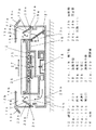
図1、図2において、12は被加熱器具としての調理プレートで、調理プレートの両側にはダクト13a,13bを具備している。ダクト13a,13bの外壁には把手13c,13dが設けられ、内側には連通穴14a,14bが開けられており、調理プレート12側の開口部15a,15bと本体16側の開口部17a,17bを設けている。18は本体16内に設けられた送風手段で、ラジアル、シロッコまたは後退翼の遠心ファンから成っている。19aは吸気口で、本体16の上部に設けられており、送風手段18の吸気側と空気流路20aで連結されている。19bは排気口で、本体16の上部に設けられており、送風手段18の排気側と空気流路20bで連結されている。21は油除去手段で、例えば紙等の繊維質から成るフィルターから形成されており、空気流路20a内に設けられている。吸気口19aと排気口19bの上面には開閉蓋22a,22bが回転軸23a,23bを介して回転自在に取り付けられている。24a,24bは突出部で、ダクト13a,13bの底面に具備されており、調理プレート12を本体16に載置する際に、突出部24a,24bが回転軸23a,23bより外側に位置する開閉蓋22a,22bを押すことで、開閉蓋22a,22bが開き(矢印Aのように)、開口部17aが吸気口19aと、開口部17bが排気口19bとそれぞれ接合される。25はトッププレートで、本体16の上面に設けられており、調理プレート12を載せている。26は加熱手段を構成している加熱コイルで、本体16内に設けられた駆動回路(図示せず。)から供給される高周波電流が加熱コイル26に流れることにより、高周波磁界を発生させ調理プレート12を誘導加熱する。27は温度センサーで駆動回路に接続されており、調理プレート12の温度を検出しながら所定の温度で制御している。
【0012】
次に、本実施例における作用について説明する。加熱コイル26に通電すると調理プレート12が誘導加熱され、調理プレート12の上に肉や野菜等の食材を載せて焼くことができる。食材が焼けてくると調理プレート12の上に油煙が発生する。この時、送風手段18のファンを駆動させることによって、ダクト13aに設けられた開口部15a(以下、吸込み部15aと呼ぶ)から吸気し、ダクト13bに設けられた開口部15b(以下、吹出し部15bと呼ぶ)から排気する空気の流れが矢印Bのように形成されることで、上記調理プレート12の上面に発生する油煙は吸込み部15aに吸引され、空気通路20a内に設けられた油除去手段21に油煙は吸着されることになる。したがって、上記作用によって油煙が部屋に拡散することがない、また、ダクト13a,13bの外壁に調理プレート12の把手13c,13dを形成することで、除煙中ダクト13a,13bの連通穴14a,14bに空気が流れダクト13a,13bを冷却するため、調理プレート12からの熱が把手13c,13dに伝わりにくく、把手13c,13dの温度は上昇しない。また、ダクト13a,13bと把手13c,13dが共通部品となることでコスト低減やデザイン性向上が図れるとともに、清掃箇所も1箇所にまとまり使い勝手が向上する。さらに、鍋料理等の除煙が必要がない時にはダクト13a,13bの付いた調理プレート12を取外すことで、吹出し部15bと吸込み部15aとを無くすことができ、鍋使用時に違和感の無い形態となる。さらに、本体16側に吹出し部15bと吸込み部15aとを無くすことができ、その分本体16が小型化になる。また、調理プレート12を本体16に載置するだけで、開閉蓋22a,22bが開き、開口部17aが吸気口19aと、開口部17bが排気口19bとそれぞれ接合され、使い勝手が向上する。
【0013】
(実施例2)
図3において、ダクト28に磁石29を具備し、開閉蓋30にカラー鋼板やステンレス板等の磁性金属31を取り付け、磁石29と磁性金属31とが回転軸32から離れた部分で吸着する位置に構成している。その他の部分は実施例1と同様のため、説明を省略する。
【0014】
これにより、実施例1と同様に調理プレート33を本体34に設置する際に磁石29が磁性金属31を吸着し、矢印Cのように開閉蓋30を開けることができ、使用勝手が向上する。この構成により、開閉蓋30を押すことなく開け閉めが確実にでき、開閉蓋30の表面に傷などをつけることがない。
【0015】
(実施例3)
図4、図5において、35は被加熱器具の調理プレートである。36は本体で、両側に筒状の連結部37a,37bを上下方向(矢印D)に回転自在に備え、連結部37a,37bには着脱自在にダクト38a,38bを取付け、ダクト38aには吸気口(吸込み部)39aを設け、ダクト38bには排気口(吹出し部)39bを備えている。40は本体36内に設けられた送風手段で、ラジアル、シロッコまたは後退翼の遠心ファンから成っている。送風手段40の吸気側と吸気口39aとは空気流路41aで連結されている。また、送風手段40の排気側と排気口39bとは空気流路41bで連結されている。42は油除去手段で、例えば紙等の繊維質から成るフィルターから形成されており、吸気側の連結部37aとダクト38aとの間に取付けられている。ダクト38a,38bは上方に回転させると吸気口39aと排気口39bは略対向する位置となり、下方に回転させると設置面43に接するまで下がる構成となっている。44はトッププレートで、本体36の上面に設けられており、調理プレート35を載せている。45は加熱手段を構成している加熱コイルで、本体36内に設けられた駆動回路(図示せず。)から供給される高周波電流が加熱コイル45に流れることにより、高周波磁界を発生させ調理プレート35を誘導加熱する。46は温度センサーで駆動回路に接続されており、調理プレート35の温度を検出しながら所定の温度で制御している。47は把手で、調理プレート35に取りつけられている。 次に、本実施例における作用について説明する。肉等の食材を焼くときには、調理プレート35をトッププレート44の上に載せ、ダクト38a,38bを上方に回転させ、調理プレート35より高い位置で吸気口39aと排気口39bとを略対向する位置に固定する。次に、加熱コイル45に通電すると調理プレート35が誘導加熱され、食材が焼けてくると調理プレート35の上に油煙が発生する。この時、送風手段40のファンを駆動させることによって、矢印Eのように吸気口(吸込み部)39aから吸気し、排気口(吹出し部)39bから排気する空気の流れが形成されることで、上記調理プレート35の上面に発生する油煙は吸込み部39aに吸引され、連結部37aとダクト38aとの間に取付けられている油除去手段42に油煙は吸着されることになる。また、調理プレート35のかわりに被加熱器具として鍋を用いる際には、ダクト38a,38bを下方の設置面43側に回転させることで、本体36の上面への飛び出しが無くなり、違和感無く使用でき、また、除煙のための部材(ダクト38a,38b等)を目立たなくすることができ、デザイン性も向上する。さらに、連結部37a,37bからダクト38a,38bが着脱でき、一番汚れる部材を取外して洗うことができ、また、その着脱部に油除去手段42を備えているため、清掃性や操作性が向上する。
【0016】
なお、各実施例において、加熱手段を加熱コイル26,45を用いた誘導加熱としているが、本体16,34,36上面にヒーター(シーズヒーター,プレートヒーター,ハロゲンヒーター等)を用いて加熱する方式としても良い。さらに、各実施例において、被加熱器具として調理プレート12,33,35を用いたが、若干深みのある鍋風の物でも良く、要は、各実施例のように調理プレート12,33,35の上面に吹出し部15b,39bから吸込み部15a,39aに送風する風流れができれば良い。また、各実施例において、送風手段18,40を遠心ファンで構成し、本体16,34,36の薄型を図っているが、本体高さ等を変更することで軸流ファンや斜流ファン等その他の形態を使用しても良い。さらに、送風手段18,40の吸気側と排気側とにそれぞれファンを設ける等、複数の送風手段を具備しても良い。また、本実施例ではダクト13a,13bの外壁に把手13c,13dを設けているが、把手13c,13dをダクト13a,13bに必ず設ける必要は無く、要は被加熱器具としての調理プレート12の両側に設けられたダクト13a,13bの開口部17a,17bが本体16の吸気口19a,19bと連結できる構成であれば、調理プレート12を使用する際には除煙ができ、鍋料理等の除煙が必要がない時には違和感の無い形態となる。
【0017】
【発明の効果】
請求項1記載の発明の加熱調理器は、被加熱器具を本体に設置した際に前記突出部が開閉蓋の回転軸から離れた部分に当接し、開閉蓋を開くので、予め本体の吸気口および排気口に設けられた蓋を取り外して被加熱器具を置く必要が無いので、使い勝手がさらに向上する。
【0018】
請求項2記載の発明の加熱調理器は、被加熱器具を本体に設置した際に磁石と磁性金属とが開閉蓋の回転軸から離れた部分で吸着し、開閉蓋を開くので、上記同様使い勝手が向上するとともにより確実な開閉機構を提供することができる。
【0019】
請求項3記載の発明の加熱調理器は、ダクトの外壁に被加熱器具の把手を形成することで、除煙中ダクトの連通穴に空気が流れダクトを冷却するため、被加熱器具からの熱が把手に伝わりにくく、把手の温度は上昇しない。また、ダクトと把手が共通部品となることでコスト低減やデザイン性向上が図れるとともに、清掃箇所も1箇所にまとまり使い勝手が向上する。
【0020】
請求項4記載の発明の加熱調理器は、両ダクトを下側に回転させた際にはダクトが設置面側に下がる構成であり、除煙が必要でないときは吹出し部や吸込み部からなるダクトを目立たなくすることができ、鍋等の被加熱器具を用いる際にも違和感なく使用できる。また、被加熱器具の中央に吸込み部も無く使い勝手が向上する。
【0021】
請求項5記載の発明の加熱調理器は、ダクトと連結部とを着脱自在にし、吸込み側のダクトと連結部との接合部近傍に油煙除去手段を設けており、ダクトを外して洗うことができ、また、油煙除去手段の着脱も容易になることで、操作性がより向上する。
【図面の簡単な説明】
【図1】 本発明の第1の実施例を示す加熱調理器の断面図
【図2】 本発明の第1の実施例を示す加熱調理器の被加熱器具を外した時の斜視図
【図3】 本発明の第2の実施例を示す加熱調理器の要部断面図
【図4】 本発明の第3の実施例を示す加熱調理器の断面図
【図5】 本発明の第3の実施例を示す加熱調理器の斜視図
【図6】 従来例を示す加熱調理器の断面図
【符号の説明】
12,33,35 調理プレート
13a,13b,28,38a,38b ダクト
13c,13d 把手
14a,14b 連通穴
15a,15b 開口部
16,34,36 本体
17a,17b 開口部
18,40 送風手段
19a,39a 吸気口
19b,39b 排気口
21,42 油除去手段
22a,22b,30 開閉蓋
23a,23b,32 回転軸
24a,24b 突出部
26,45 加熱コイル
29 磁石
31 磁性金属
37a,37b 連結部
43 設置面[0001]
BACKGROUND OF THE INVENTION
The present invention relates to a cooking device that reduces oil smoke generated when cooking yakiniku.
[0002]
[Prior art]
A conventional cooking device has a structure as shown in FIG. 1 is a cooking plate which is a tool to be heated, 2 is a heating means for heating the
[0003]
[Problems to be solved by the invention]
However, in the conventional configuration as described above, the
[0004]
The present invention solves such a conventional problem, and improves the usability of the cooking plate surface and reduces the size of the product body in a heating cooker that reduces oil smoke generated when cooking grilled meat and the like. Furthermore, it aims at providing the structure without a sense of incongruity also in use of a pan etc.
[0005]
[Means for Solving the Problems]
In order to solve the above-described problems, the present invention provides a heating means provided in the upper part of the main body, an intake port and an exhaust port provided in the outer shell of the main body , a rotatable opening / closing lid provided in the intake port and the exhaust port, A duct provided at both ends of the appliance to be heated , a protrusion provided at a portion of the duct facing the opening / closing lid, and a suction portion and a blow-out portion including communication holes provided in the duct. when placed on the body, the suction unit and the suction port, said coupled outlet and said blowing unit, the oil removing means to the intake side in the path to the suction side of the blower means from the suction unit An opening of the suction portion and an opening of the blow-out portion are substantially opposed to each other, form an air flow from the blow-out portion to the suction portion , and the protrusion rotates the opening / closing lid Touch the part away from the shaft and open the lid With cooker, previously since the body of the inlet and remove the lid provided in the exhaust port is not required to place the heated tool, usability is further improved.
[0006]
DETAILED DESCRIPTION OF THE INVENTION
The invention according to
[0007]
According to a second aspect of the present invention, a rotatable opening / closing lid is provided at the intake port and the exhaust port of the main body, and a magnet is provided on at least one of the opening / closing lid and a duct portion opposed thereto, and a magnetic metal is provided on the other side. When the heated appliance is installed on the main body, the magnet and magnetic metal are attracted at the part away from the rotation axis of the opening / closing lid, and the opening / closing lid is opened. A mechanism can be provided.
[0008]
Invention according to
[0009]
According to a fourth aspect of the present invention, a heating means is provided on the upper part of the main body, a cylindrical connecting part that can be rotated in the vertical direction is provided on both sides of the main body, and a duct comprising a communication hole is attached to one end of the connecting part. An intake port is provided with one of the ducts as a suction portion, an exhaust port is provided with the other as a blow-off portion, an oil removal means is provided in the intake-side path including the suction portion, and the cooking means is heated above the heating means. When the instrument is placed and both ducts are rotated upward, the air intake and exhaust ports of both ducts are in a substantially opposite position, creating an air flow from the air exhaust to the air intake. When it is rotated downward, the duct is configured to go down to the installation surface side where the main body is installed , and when smoke removal is not necessary, the duct consisting of the blowing part and the suction part can be made inconspicuous, When using heated appliances such as pots That. In addition, there is no suction part in the center of the appliance to be heated, which improves usability.
[0010]
In the invention according to
[0011]
【Example】
Example 1
In FIG. 1 and FIG. 2, 12 is a cooking plate as a tool to be heated, and is provided with
[0012]
Next, the operation of this embodiment will be described. When the heating coil 26 is energized, the cooking plate 12 is induction-heated, and ingredients such as meat and vegetables can be placed on the cooking plate 12 and baked. When the ingredients are baked, oily smoke is generated on the cooking plate 12. At this time, by driving the fan of the air blowing means 18, air is sucked from an opening 15a provided in the
[0013]
(Example 2)
In FIG. 3, a
[0014]
Thereby, when installing the cooking plate 33 in the
[0015]
(Example 3)
4 and 5, reference numeral 35 denotes a cooking plate for the appliance to be heated. A main body 36 is provided with cylindrical connecting portions 37a and 37b on both sides so as to be rotatable in the vertical direction (arrow D). Ducts 38a and 38b are detachably attached to the connecting portions 37a and 37b. A port (suction part) 39a is provided, and the duct 38b is provided with an exhaust port (blowout part) 39b. Reference numeral 40 denotes air blowing means provided in the main body 36, which comprises a radial, sirocco or swept centrifugal fan. The intake side of the blowing means 40 and the intake port 39a are connected by an air flow path 41a. Further, the exhaust side of the air blowing means 40 and the exhaust port 39b are connected by an air flow path 41b. An oil removing means 42 is formed of a filter made of a fiber such as paper, and is attached between the intake side connecting portion 37a and the duct 38a. When the ducts 38a and 38b are rotated upward, the intake port 39a and the exhaust port 39b are substantially opposed to each other. When the ducts 38a and 38b are rotated downward, the ducts 38a and 38b are lowered until they contact the installation surface 43. Reference numeral 44 denotes a top plate which is provided on the upper surface of the main body 36 and on which the cooking plate 35 is placed. Reference numeral 45 denotes a heating coil that constitutes heating means. When a high-frequency current supplied from a drive circuit (not shown) provided in the main body 36 flows through the heating coil 45, a high-frequency magnetic field is generated to produce a cooking plate. 35 is induction heated. A temperature sensor 46 is connected to the drive circuit, and is controlled at a predetermined temperature while detecting the temperature of the cooking plate 35. A handle 47 is attached to the cooking plate 35. Next, the operation of this embodiment will be described. When baking ingredients such as meat, the cooking plate 35 is placed on the top plate 44, the ducts 38a, 38b are rotated upward, and the intake port 39a and the exhaust port 39b are substantially opposed to each other at a position higher than the cooking plate 35. Secure to. Next, when the heating coil 45 is energized, the cooking plate 35 is induction-heated, and when the food is baked, oily smoke is generated on the cooking plate 35. At this time, by driving the fan of the air blowing means 40, the flow of air that is sucked from the air inlet (suction part) 39a and exhausted from the air outlet (blowout part) 39b as shown by the arrow E is formed. The smoke generated on the upper surface of the cooking plate 35 is sucked into the suction portion 39a, and the smoke is adsorbed by the oil removing means 42 attached between the connecting portion 37a and the duct 38a. Moreover, when using a pan as a tool to be heated instead of the cooking plate 35, the ducts 38a and 38b are rotated to the lower installation surface 43 side, so that the upper surface of the main body 36 is not jumped out and can be used without a sense of incongruity. In addition, smoke removal members (ducts 38a, 38b, etc.) can be made inconspicuous, and the design can be improved. Further, the ducts 38a and 38b can be attached and detached from the connecting portions 37a and 37b, the most dirty member can be removed and washed, and the oil removing means 42 is provided in the attaching and detaching portion, so that the cleaning property and the operability are improved. improves.
[0016]
In each of the embodiments, the heating means is induction heating using the heating coils 26 and 45. However, a heating method using a heater (seeds heater, plate heater, halogen heater, etc.) on the upper surfaces of the
[0017]
【The invention's effect】
In the heating cooker according to the first aspect of the present invention, when the appliance to be heated is installed in the main body, the protrusion comes into contact with a portion away from the rotation axis of the open / close lid and opens the open / close lid. In addition, since it is not necessary to remove the lid provided on the exhaust port and place the appliance to be heated, the usability is further improved.
[0018]
In the heating cooker according to the second aspect of the present invention, when the appliance to be heated is installed in the main body, the magnet and the magnetic metal are adsorbed at a part away from the rotation shaft of the opening / closing lid, and the opening / closing lid is opened. As a result, a more reliable opening / closing mechanism can be provided.
[0019]
In the heating cooker according to the third aspect of the invention, the handle of the heated appliance is formed on the outer wall of the duct so that air flows into the communication hole of the duct during smoke removal and cools the duct. However, the temperature of the handle does not rise. In addition, since the duct and the handle are common parts, the cost can be reduced and the design can be improved, and the cleaning location can be integrated into one location for improved usability.
[0020]
The heating cooker according to the invention of
[0021]
The cooking device of the invention according to
[Brief description of the drawings]
FIG. 1 is a cross-sectional view of a heating cooker showing a first embodiment of the present invention. FIG. 2 is a perspective view of the heating cooker showing a first embodiment of the present invention when a heated appliance is removed. 3 is a cross-sectional view of a main part of a heating cooker showing a second embodiment of the present invention. FIG. 4 is a cross-sectional view of a heating cooker showing a third embodiment of the present invention. FIG. 6 is a perspective view of a cooking device showing an embodiment. FIG. 6 is a cross-sectional view of a cooking device showing a conventional example.
12, 33, 35
Claims (5)
Priority Applications (1)
| Application Number | Priority Date | Filing Date | Title |
|---|---|---|---|
| JP34982899A JP4055314B2 (en) | 1999-12-09 | 1999-12-09 | Cooker |
Applications Claiming Priority (1)
| Application Number | Priority Date | Filing Date | Title |
|---|---|---|---|
| JP34982899A JP4055314B2 (en) | 1999-12-09 | 1999-12-09 | Cooker |
Publications (2)
| Publication Number | Publication Date |
|---|---|
| JP2001161570A JP2001161570A (en) | 2001-06-19 |
| JP4055314B2 true JP4055314B2 (en) | 2008-03-05 |
Family
ID=18406394
Family Applications (1)
| Application Number | Title | Priority Date | Filing Date |
|---|---|---|---|
| JP34982899A Expired - Fee Related JP4055314B2 (en) | 1999-12-09 | 1999-12-09 | Cooker |
Country Status (1)
| Country | Link |
|---|---|
| JP (1) | JP4055314B2 (en) |
Families Citing this family (5)
| Publication number | Priority date | Publication date | Assignee | Title |
|---|---|---|---|---|
| NL1033840C2 (en) * | 2007-05-12 | 2008-11-13 | Powa B V | Food e.g. raclette, cooking device, has parts, heating plate, and hood which includes built-in-fan and filter, where hood is provided at bottom for admitting air filter |
| KR101944778B1 (en) * | 2017-09-19 | 2019-02-07 | 주식회사 동서엔지니어링 | Pre-processing equipment of cooking rice for making nurungji |
| CN108535256B (en) * | 2018-06-06 | 2024-02-09 | 岭南师范学院 | Marine product species quick identification device |
| CN113693429B (en) * | 2020-05-21 | 2022-05-03 | 佛山市顺德区美的电热电器制造有限公司 | Cooking utensil and processing apparatus |
| DE102022208147A1 (en) | 2022-08-04 | 2024-02-15 | BORA - Vertriebs GmbH & Co KG | Cooking system with extractor hood |
-
1999
- 1999-12-09 JP JP34982899A patent/JP4055314B2/en not_active Expired - Fee Related
Also Published As
| Publication number | Publication date |
|---|---|
| JP2001161570A (en) | 2001-06-19 |
Similar Documents
| Publication | Publication Date | Title |
|---|---|---|
| WO2014084335A1 (en) | Heating cooker | |
| US20040055477A1 (en) | Rotisserie oven | |
| KR20060108022A (en) | Convection chamber of cooking device | |
| WO2009124438A1 (en) | A cooking device which can stir food automatically | |
| KR100649602B1 (en) | Cooking Device | |
| JP4055314B2 (en) | Cooker | |
| CN213464725U (en) | Cooking utensil | |
| CN213464801U (en) | Cooking utensil | |
| JP2003050033A (en) | Range-hood fan | |
| WO2022062787A1 (en) | Cooking appliance | |
| JP4883528B2 (en) | Grill equipment | |
| JP2004076954A (en) | Cooking device | |
| JPH10165242A (en) | Integrated type heating cooler | |
| JP3879287B2 (en) | Cooker | |
| JP4462778B2 (en) | Cooker | |
| JP3942427B2 (en) | Cooker | |
| JP2001070175A (en) | Heat cooker | |
| JP3298540B2 (en) | rice cooker | |
| JP6037819B2 (en) | Cooker | |
| CN216293817U (en) | Multi-station horizontal cooking appliance | |
| CN217827590U (en) | Air duct structure of cooking device | |
| JPH0716161A (en) | Heating cooker and handle for cooking plate | |
| KR200374784Y1 (en) | Food cooking device | |
| KR20060104419A (en) | Oven | |
| JPH10295554A (en) | Hot plate |
Legal Events
| Date | Code | Title | Description |
|---|---|---|---|
| A621 | Written request for application examination |
Free format text: JAPANESE INTERMEDIATE CODE: A621 Effective date: 20060314 |
|
| RD01 | Notification of change of attorney |
Free format text: JAPANESE INTERMEDIATE CODE: A7421 Effective date: 20060412 |
|
| A977 | Report on retrieval |
Effective date: 20070828 Free format text: JAPANESE INTERMEDIATE CODE: A971007 |
|
| A131 | Notification of reasons for refusal |
Free format text: JAPANESE INTERMEDIATE CODE: A131 Effective date: 20070904 |
|
| A521 | Written amendment |
Free format text: JAPANESE INTERMEDIATE CODE: A523 Effective date: 20071005 |
|
| TRDD | Decision of grant or rejection written | ||
| A01 | Written decision to grant a patent or to grant a registration (utility model) |
Effective date: 20071120 Free format text: JAPANESE INTERMEDIATE CODE: A01 |
|
| A61 | First payment of annual fees (during grant procedure) |
Effective date: 20071203 Free format text: JAPANESE INTERMEDIATE CODE: A61 |
|
| FPAY | Renewal fee payment (prs date is renewal date of database) |
Year of fee payment: 3 Free format text: PAYMENT UNTIL: 20101221 |
|
| FPAY | Renewal fee payment (prs date is renewal date of database) |
Year of fee payment: 3 Free format text: PAYMENT UNTIL: 20101221 |
|
| FPAY | Renewal fee payment (prs date is renewal date of database) |
Free format text: PAYMENT UNTIL: 20111221 Year of fee payment: 4 |
|
| LAPS | Cancellation because of no payment of annual fees |