JP4054487B2 - Pointer mark display control device, display control method, display control system, and storage medium - Google Patents
Pointer mark display control device, display control method, display control system, and storage medium Download PDFInfo
- Publication number
- JP4054487B2 JP4054487B2 JP20143199A JP20143199A JP4054487B2 JP 4054487 B2 JP4054487 B2 JP 4054487B2 JP 20143199 A JP20143199 A JP 20143199A JP 20143199 A JP20143199 A JP 20143199A JP 4054487 B2 JP4054487 B2 JP 4054487B2
- Authority
- JP
- Japan
- Prior art keywords
- pointer mark
- pointer
- display screen
- display control
- point
- Prior art date
- Legal status (The legal status is an assumption and is not a legal conclusion. Google has not performed a legal analysis and makes no representation as to the accuracy of the status listed.)
- Expired - Fee Related
Links
Images


Classifications
-
- G—PHYSICS
- G06—COMPUTING; CALCULATING OR COUNTING
- G06F—ELECTRIC DIGITAL DATA PROCESSING
- G06F3/00—Input arrangements for transferring data to be processed into a form capable of being handled by the computer; Output arrangements for transferring data from processing unit to output unit, e.g. interface arrangements
- G06F3/01—Input arrangements or combined input and output arrangements for interaction between user and computer
- G06F3/03—Arrangements for converting the position or the displacement of a member into a coded form
- G06F3/033—Pointing devices displaced or positioned by the user, e.g. mice, trackballs, pens or joysticks; Accessories therefor
-
- G—PHYSICS
- G06—COMPUTING; CALCULATING OR COUNTING
- G06F—ELECTRIC DIGITAL DATA PROCESSING
- G06F3/00—Input arrangements for transferring data to be processed into a form capable of being handled by the computer; Output arrangements for transferring data from processing unit to output unit, e.g. interface arrangements
- G06F3/01—Input arrangements or combined input and output arrangements for interaction between user and computer
- G06F3/048—Interaction techniques based on graphical user interfaces [GUI]
- G06F3/0481—Interaction techniques based on graphical user interfaces [GUI] based on specific properties of the displayed interaction object or a metaphor-based environment, e.g. interaction with desktop elements like windows or icons, or assisted by a cursor's changing behaviour or appearance
- G06F3/04812—Interaction techniques based on cursor appearance or behaviour, e.g. being affected by the presence of displayed objects
-
- G—PHYSICS
- G09—EDUCATION; CRYPTOGRAPHY; DISPLAY; ADVERTISING; SEALS
- G09G—ARRANGEMENTS OR CIRCUITS FOR CONTROL OF INDICATING DEVICES USING STATIC MEANS TO PRESENT VARIABLE INFORMATION
- G09G5/00—Control arrangements or circuits for visual indicators common to cathode-ray tube indicators and other visual indicators
- G09G5/14—Display of multiple viewports
Description
【0001】
【発明の属する技術分野】
本発明は、カーソル等のポインタマークの表示制御技術に関する。
【0002】
【従来の技術】
近年、パーソナルコンピュータ等の情報処理装置では、表示装置としてビットマップディスプレイを用い、そのビットマップディスプレイ上の座標位置を指示するポインティングデバイスとしてマウスや電子ペン等を用いることにより、入力をアイコン等の図形情報により行えるようにしたグラフィカル・ユーザ・インターフェースが一般化してきている。
【0003】
この種のグラフィカル・ユーザ・インターフェースにおいては、表示画面上のアイコン、文字入力位置等の座標位置を指示する場合は、その指定位置にポインタマークを表示している。このポインタマークの形状としては、一般に、左上向きの矢印のカーソル、縦棒型のIビーム(キャレット)等が用いられている。なお、本明細書においては、「形状」とういう用語を、純粋な意味での形状の他に向きをも加味した意味で使用している。
【0004】
また、より良好なグラフィカル・ユーザ・インターフェースを実現すべく、表示画面上の領域に応じて異なった形状のポインタマークを表示するようにした装置も知られている。さらに、特開平06−289835号公報では、表示画面上の隅を指定する場合にもポインタマークを表示できるように、表示画面上の指示位置に応じてポインタマークの形状(向き)を変更する装置が提案されている。
【0005】
さらに、このような情報処理装置は、近年、プレゼンテーションにも利用されるようになった。この種のプレゼンテーションシステムでは、例えば、講習会や技術説明会等において、パーソナルコンピュータの表示画面に表示されている映像信号を液晶プロジェクタ等の投影装置に入力し、この投影装置により上記の映像を大型スクリーンに投影して大勢の参会者に一括して資料等を提示している。そして、技術説明会等の説明者は、パーソナルコンピュータのポインティングデバイスにより説明箇所(着目位置)にポインタマークを移動させながら説明を進めていく。
【0006】
このようなプレゼンテーションシステムでも、従来は、ポインタマークの形状としては、情報処理装置単体で用いられていた形状をそのまま流用していた。
【0007】
【発明が解決しようとする課題】
ところで、技術説明会等でプレゼンテーションシステムを利用する場合、技術説明会等という性質上、参会者の視線は、投影画面にのみ集中することなく、投影画面上のポインタマークの位置と説明者とを往復することが多い。このため、プレゼンテーションシステムでは、ポインタマークの形状は、説明者と投影画面上の着目位置を自然な形で連結するのが望ましい。
【0008】
しかし、従来のポインタマークの形状は、情報処理装置の表示画面だけを見ることを前提にして決められており、プレゼンテーションシステムに適用することは想定されていないため、上記のように説明者と投影画面上の着目位置を自然な形で連結するのは困難であった。
【0009】
本発明は、このような背景の下になされたもので、その課題は、プレゼンテーションシステム等に適用するのに好適なポインタマークを表示できるようにすることにある。
【0010】
上記課題を解決するため、本発明は、表示画面上に複数のウィンドウを表示するウィンドウ表示手段と、前記表示画面上の任意の点を指示する指示手段と、前記表示画面上の基準点を予め設定する設定手段と、前記指示手段により表示画面上の任意の点が指示された際、該指示に係る指示点と前記設定手段により設定された基準点とを結ぶ方向のポインタマークを生成する生成手段と、前記生成手段により生成されたポインタマークについて、前記表示画面上の前記複数のウィンドウのうち、前記指示点の存在しないウィンドウに存在するポインタマークを消去することにより、前記生成手段により生成されたポインタマークを、前記表示画面上の前記複数のウィンドウのうち、前記指示点の存在するウィンドウと、前記表示画面上の前記複数のウィンドウ以外の表示領域である背景部にのみに表示させる表示制御手段とを備えている。
【0011】
また、本発明は、表示画面上に複数のウィンドウを表示するウィンドウ表示工程と、前記表示画面上の任意の点を指示する指示工程と、前記表示画面上の基準点を予め設定する設定工程と、前記指示工程により表示画面上の任意の点が指示された際、該指示に係る指示点と前記設定工程により設定された基準点とを結ぶ方向のポインタマークを生成する生成工程と、前記生成工程により生成されたポインタマークについて、前記表示画面上の前記複数のウィンドウのうち、前記指示点の存在しないウィンドウに存在するポインタマークを消去することにより、前記生成工程により生成されたポインタマークを、前記表示画面上の前記複数のウィンドウのうち、前記指示点の存在するウィンドウと、前記表示画面上の前記複数のウィンドウ以外の表示領域である背景部にのみに表示させる表示制御工程とを備えている。
【0012】
また、本発明は、情報処理装置の表示画面に表示されている画像を投影装置に転送してスクリーンに投影させる表示制御システムにおいて、前記情報処理装置は、前記表示画面上に複数のウィンドウを表示するウィンドウ表示手段と、前記表示画面上の任意の点を指示する指示手段と、前記表示画面上の基準点を予め設定する設定手段と、前記指示手段により表示画面上の任意の点が指示された際、該指示に係る指示点と前記設定手段により設定された基準点とを結ぶ方向のポインタマークを生成する生成手段と、前記生成手段により生成されたポインタマークについて、前記表示画面上の前記複数のウィンドウのうち、前記指示点の存在しないウィンドウに存在するポインタマークを消去することにより、前記生成手段により生成されたポインタマークを、前記表示画面上の前記複数のウィンドウのうち、前記指示点の存在するウィンドウと、前記表示画面上の前記複数のウィンドウ以外の表示領域である背景部にのみに表示させる表示制御手段とを備えている。
【0013】
また、本発明は、情報処理装置の表示画面に表示されている画像を投影装置に転送してスクリーンに投影させるための制御プログラムを記憶する記憶媒体であって、前記制御プログラムは、前記表示画面上に複数のウィンドウを表示するウィンドウ表示ルーチンと、前記表示画面上の任意の点を指示する指示ルーチンと、前記表示画面上の基準点を予め設定する設定ルーチンと、前記指示ルーチンにより表示画面上の任意の点が指示された際、該指示に係る指示点と前記設定ルーチンにより設定された基準点とを結ぶ方向のポインタマークを生成する生成ルーチンと、前記生成ルーチンにより生成されたポインタマークについて、前記表示画面上の前記複数のウィンドウのうち、前記指示点の存在しないウィンドウに存在するポインタマークを消去することにより、前記生成ルーチンにより生成されたポインタマークを、前記表示画面上の前記複数のウィンドウのうち、前記指示点の存在するウィンドウと、前記表示画面上の前記複数のウィンドウ以外の表示領域である背景部にのみに表示させる表示制御ルーチンとを含んでいる。
【0014】
また、本発明では、前記表示制御手段は、前記生成手段により生成されたポインタマークのうち前記指示点の存在するウィンドウに含まれる部分を複製する複製手段と、前記生成手段により生成されたポインタマークのうち前記表示画面上の前記複数のウィンドウに含まれる部分を消去する消去手段と、前記複製手段で複製されたポインタマークと、前記表示画面上の前記複数のウィンドウ以外の領域である背景部に含まれるポインタマークを合成する合成手段とを更に備えている。
【0015】
また、本発明では、前記生成手段は、予め雛形として登録されたポインタマークを加工することにより、前記指示点と基準点とを結ぶ方向のポインタマークを生成している。
【0016】
また、本発明では、前記雛形として登録されたポインタマークは、ビットマップデータ形式で記述されている。
【0017】
また、本発明では、前記雛形として登録されたポインタマークは、ベクトルデータ形式で記述されている。
【0018】
また、本発明では、前記生成手段は、前記基準点から指示点に向かう矢印形のポインタマークを生成している。
【0019】
また、本発明では、前記設定手段は、複数の基準点を予め設定し、前記生成手段は、設定された複数の基準点の中から任意に選択された基準点を用いてポインタマークを生成している。
【0020】
また、本発明では、前記表示制御手段は、前記生成手段により生成されたポインタマークを点滅させながら前記表示画面上に表示させている。
【0021】
また、本発明では、前記表示制御手段は、前記生成手段により生成されたポインタマークをドットイメージで表示させる際に、前記基準点から指示点に向かって1ドット、又は数ドットの単位で順次点灯させていく。
【0022】
また、本発明では、前記表示画面に表示されている画像を投影装置に転送してスクリーンに投影させるための転送制御手段を備えている。
【0023】
また、本発明では、前記生成手段は、予め雛形として登録されたビットマップ画像形式の明度勾配を持つポインタマークを用いて単調な明度勾配を持つポインタマークを生成している。
【0026】
また、本発明では、前記生成手段は、予め雛形として登録されたビットマップ画像形式の明度勾配を持たないポインタマークの画素値を変化させることにより、単調な明度勾配を持つポインタマークを生成している。
【0027】
また、本発明では、前記生成手段は、予め雛形として登録されたベクトルデータ形式の明度勾配を持たないポインタマークをビットマップ画像形式に変形した後に、該ビットマップ画像形式のポインタマークの画素値を変化させることにより、単調な明度勾配を持つポインタマークを生成している。
【0030】
また、本発明では、前記生成手段は、予め雛形として登録されたベクトルデータ形式のポインタマークをビットマップ画像形式に変形した後に、該ポインタマークの画素値を変化させることにより、単調な明度勾配を持つポインタマークを生成している。
【0031】
また、本発明では、前記表示制御手段は、前記生成手段により生成されたポインタマークを指示点に特定の図形を配して表示させている。
【0032】
また、本発明では、前記表示制御手段は、前記生成手段により生成されたポインタマークを基準点に特定の図形を配して表示させている。
【0033】
【発明の実施の形態】
図1は、本発明の一実施形態に係るポインタマーク表示制御装置の機能ブロック図である。このポインタマーク表示制御装置は、パーソナルコンピュータ等の情報処理装置10に搭載されたものであり、プレゼンテーションシステム等に適用することを想定したものである。
【0034】
図1において、11はディスプレイ装置20の表示画面21(図2参照)上の一点を指示する座標指示部、12は表示画面21上の基準点を設定する基準点設定部である。これら座標指示部11、基準点設定部12の操作用のデバイスとしては、マウス、電子ペンなどを用いており、座標指示部11、基準点設定部12は、マウス、電子ペンにより指示された座標位置を認識する。そして、座標指示部11は、認識した座標位置をポインタマーク22(図2参照)の先端位置の座標位置データとして処理し、基準点設定部12は、認識した座標位置をポインタマーク22の始点位置の座標位置データとして登録する。
【0035】
13はポインタマーク22の表示制御を行うポインタ表示制御部である。14はポインタ生成部であり、座標指示部11により処理されたポインタマーク22の先端位置の座標位置データと、基準点設定部12により登録されたポインタマーク22の始点位置の座標位置データとに基づいてポインタマーク22を生成する。そして、ポインタ表示制御部13は、ポインタ生成部14により生成されたポインタマーク22をディスプレイ装置20の表示画面21(図2参照)に表示すると共に、表示画面21に表示されている画像(ポインタマーク22を含む)の画像信号を、液晶プロジェクタ等の投影装置18に送信する。そして、入力された画像信号に係る画像は、投影装置18により大型スクリーン19に投影される。
【0036】
座標指示部11、基準点設定部12、ポインタ表示制御部13、及びポインタ生成部14は、CPU15の制御の下に上記の機能を果たすように構成されている。この際、CPU15は、RAM17をワークエリア等として利用しながら、ROM16に格納された図3〜5,8,10,12に対応する制御プログラムに従って上記の制御を行う。
【0037】
図2は、ポインタ表示制御部13の制御により表示されたポインタマーク22を、説明者との位置関係が明らかになるように示した図である。
【0038】
図2において、表示画面21には、説明者が使用する情報処理装置10からの情報が表示される。22は本発明に特有なポインタマーク22であり、23は基準点設定部12により設定された基準点を示し、24は座標指示部11により指示された指示点を示している。
【0039】
なお、基準点設定部12により設定する基準点は、複数設定することができる。そして、例えば、説明者25が図2の左側(表示画面21の左側、厳密に言えば、大型スクリーン19の左側)の位置に立って説明する場合は、表示画面21の左側の基準点23を用いてポインタマーク22が形成され、表示画面21の右側(厳密に言えば、大型スクリーン19の右側)の位置に立って説明する場合は、表示画面21の右側の基準点23を用いてポインタマーク22が形成されるように、ユーザが基準点23を選択する。
【0040】
図3は、1つの基準点の設定処理を示すフローチャートである。なお、このフローチャートは、図4のフローチャートにおけるステップS44の詳細な処理を示すサブルーチンに相当するものである。
【0041】
基準点設定部12は、まず、基準点として設定したい点の座標を指示するよう利用者にメッセージを表示する(ステップS31)。そして、マウス等の操作により座標データが入力されるのを待ち(ステップS32)、座標データが入力された後、その入力座標データをRAM17内の識別番号Jの基準座標用ワーク[Pointer(J).OX、Pointer(J).OY)]に格納して(ステップS33)、図4のメインフローにリターンする。
【0042】
図4は、複数の基準点の設定処理(メインルーチン)を示すフローチャートである。
【0043】
基準点設定部12は、設定可能な基準点の総数をRAM17内の変数JMaxにセットする(ステップS41)。そして、カウンタJを“1”初期化する(ステップS42)。次に、カウンタJ内のカウント値に対応するJ番目の基準点に関する各種のデータを初期化する(ステップS43)。この初期化には、当該J番目の基準点を用いてポインタマークを生成する際に使用されたポインタ図形の初期化、現在J番目の基準点として設定されている基準点の座標データの初期化などが含まれる。
【0044】
次に、図3で説明した識別番号Jの基準点の座標データの設定処理を行う(ステップS44)。次に、カウンタJを“1”だけインクリメントする(ステップS45)。そして、カウンタJ内のカウント値と変数JMaxの数値とを比較する(ステップS46)。その結果、カウンタJ内のカウント値が変数JMaxの数値以下であれば、設定可能な数の全ての基準点について未だ座標データの設定処理が完了していないことを意味するので、ステップS43に戻って、上記の処理を継続する。一方、カウンタJ内のカウント値が変数JMaxの数値より大きければ、設定可能な数の全ての基準点について座標データの設定処理が完了したことを意味するので、終了する。
【0045】
図5は、ポインタ生成部14によるポインタマーク生成処理を示すフローチャートである。なお、このポインタマーク生成処理は、複数設定された基準点のうち、ユーザにより任意に選択された基準点について実行されるものであり、図5のフローチャートは、識別番号Jの基準点が選択されたものとして記述されている。
【0046】
ポインタ生成部14は、まず、座標指示手段11により現在指示されている座標データを上記ワーク[Pointer(J).OX、Pointer(J).OY]から取得し、ワーク[Pointer(J).X、Pointer(J).Y]にセットする(ステップS51)。次に、識別番号Jの基準点を原点とした基準点と指示点との相対座標[Pointer(J).RX、Pointer(J).RY]を次式で計算する(ステップS52)。すなわち、
Pointer(J).RX=Pointer(J).X−Pointer(J).OX … (1)を算出し、
Pointer(J).RY=Pointer(J).Y−Pointer(J).OY … (2)を算出する。
【0047】
ここで、Pointer(J).OX、Pointer(J).OYは、上述したように基準点の座標である。
【0048】
次に、ステップS52にて算出した相対座標に基づいて、座標指示手段11により現在指示されている座標を、選択に係る基準点を原点とする極座標[Pointer(J).R、Pointer(J).θ]で表記すべく、次式の計算を行う(ステップS53)。すなわち、
Pointer(J).R=SQRT[Pointer(J).RX**2+Pointer(J).RY**2] … (3)を算出し、
Pointer(J).θ=atan[Pointer(j).RY、Pointer(J).RX] … (4)を算出する。
【0049】
ここで、「SQRT」は平方根を表わし、「**」はベき乗、「atan」は逆正接を表わす。
【0050】
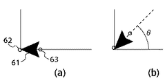
最後に、ポインタ生成部14に予め登録されたポインタ図形61(図6参照)を、そのポインタ図形61の先端を中心にして、Pointer(J).θだけ回転させたポインタマーク22を生成する(ステップS54)。
【0051】
図6は、識別番号Jに対して予め登録されたポインタ図形61に基づいて生成した例を示している。図6において、61は予め登録されたポインタ図形、62はポインタ図形の先端、63はポインタ図形の末尾を示している。ポインタ図形61を回転させる場合は、ポインタ図形61の先端62を中心として回転させることとし、例えば図6(b)に示したように、ポインタ図形61をその先端62を中心として左回りに角度θだけ回転させる。
【0052】
なお、上記ステップS54では、ポインタマーク22の全長が数式(3)で算出された長さになるように、回転されたポインタ図形61に対して直線成分を付加する処理も行っている。
【0053】
このような処理の結果、図2に示したように、生成されたポインタマーク22の方向は、基準点23と指示点24とを結ぶ線の方向となり、ポインタマーク22の先端(矢印の先端)は、指示点24に位置するようになる。この結果、資料等を表示した表示画面21上に表示されるポインタマーク22の方向は、説明者25の実際の位置と説明者25による資料等の指示点(着目位置)24との方向にほぼ対応するものとなり、説明者25と指示点24とが、講習会等の参会者にとって自然な形で連結されるので、参会者に何ら違和感を与えることはなくなる。
【0054】
[第1の応用変形例]
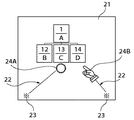
上記の実施形態では、マルチウィンドウが形成されている場合を考慮していなかったが、マルチウィンドウが形成されている場合は、図7に示したように、ポインタマーク22の指示点24が存在するウィンドウと、各ウィンドウの背景部にのみポインタマークを表示することにより、指示点24が存在しないウィンドウの情報を見やすくするようにしてもよい。
【0055】
この場合の処理を図8のフローチャートに基づいて説明する。ポインタ表示制御部13は、まず、ポインタ生成部14にてビットマップ展開されたポインタマーク22を得て、作業用ポインタ画像領域PtBufに格納する(ステップS81)。そして、ポインタマーク22の指示点24が存在するウィンドウの識別子TargetWinIDを得る(ステップS82)。
【0056】
次に、指示領域ポインタ画像領域PtBufTopの内容をクリアし(ステップS83)、作業用ポインタ画像領域PtBuf内のポインタマーク22のうち、ポインタマーク22の指示点24が存在するウィンドウであるTargetWinIDウィンドウに含まれる部分を、指示領域ポインタ画像領域PtBufTopにコピーする(ステップS84)。
【0057】
次に、表示画面21に表示されているウィンドウの総数を得て、ウィンドウ総数領域TotWinsに格納し(ステップS85)。ウィンドウ作業カウンタlwinをゼロにする(ステップS86)。そして、ウィンドウ作業カウンタlwinの値をプラス1して(ステップS87)、ウィンドウ作業カウンタlwinの値がウィンドウ総数領域TotWinsの値を超えたか否かを判別する(ステップS88)。
【0058】
その結果、lwinの値がTotWinsの値を超えていなければ、作業用ポインタ画像領域PtBuf内のポインタマーク22のうち、ウィンドウ作業カウンタlwinの値に対応するウィンドウが占める部分を消去する(ステップS89)。そして、ステップS87に戻ることにより、表示画面21に表示されている全てのウィンドウが占める部分のポインタマーク22を消去する。
【0059】
一方、ウィンドウ作業カウンタlwinの値がウィンドウ総数領域TotWinsの値を超えたと判別された場合、すなわち、全てのウィンドウと重なる部分のポインタマーク22の消去処理が完了した場合は、指示点24が存在するウィンドウ領域のポインタマーク22を復活させるべく、指示領域ポインタ画像領域PtBufTopに保存した指示点24が存在するウインドウ領域のポインターマーク22の部分を、作業用ポインタ画像領域PtBufに書込む(ステップS90)。そして、作業用ポインタ画像情報PtBuf内のポインタマーク22を表示画面バッッファの画像情報と合成して(ステップS91)、1つのポインタマータ表示処理を終了する。
【0060】
このような処理の結果、図7に示したように、ポインタマーク22は、指示点24が存在するウィンドウW1の部分22Aと、各ウインドウの背景部分22Bのみが表示され、指示点24が存在しないウィンドウW2,W3の部分は、表示されなくなるので、指示点24が存在しないウィンドウW2,W3の情報が見やすくなる。
【0061】
なお、図8の処理では、基準点23は、ウィンドウ形成領域外に設定されることを前提にしていたため、基準点23がウィンドウ内に存在する場合の処理が欠落しているが、ウィンドウ形成領域内に基準点23を設定することを容認する場合は、ポインタマーク22は、その基準点23を含むウィンドウ領域の部分をも表示させるようにすればよい。
【0062】
[第2の応用変形例]
第2の応用変形例として、図9に示したように、ポインタマーク22のグラデーション(階調)を基準点23側から指示点24側へ向かって単調に変化させることにより、ポインタマーク22に対する注目度を向上させることが考えられる。
【0063】
この場合、単調な明度(濃度)勾配を持つビットマップ画像をポインタマーク22の雛形として予めROM16等に登録しておく方式が考えられる。この登録方式では、矢線(直線成分)がある程度長いポインタマーク22を登録しておき、基準点23と指定点24との距離の長さ分だけを指定点24の方から切出して上記の回転処理を施すのが望ましい。この理由は、単調な明度勾配を持つ比較的矢線の短いビットマップ画像をポインタマーク22の雛形として予め登録した場合は、基準点23と指定点24との距離が比較的長いときに矢線(単調な明度勾配を持つもの)を付加しなければならず、その付加処理に時間を取られて登録方式における迅速処理性という効果が半減してしまうからである。
【0064】
また、当然のことながら、ポインタマーク22の雛形として明度(濃度)勾配を持たないビットマップ画像を予めROM16等に登録しておく方法も考えられる。この方式では、図10に示した処理により、ポインタマーク22の雛形に対して明度勾配を付与することができる。
【0065】
すなわち、ポインタ生成部14は、まず、図5に示した手順でポインタマーク生成処理を行う。すなわち、ポインタマークの先端が指示点24、後端が基準点23に一致するように、ピットマップ画像である雛形のポインタ図形61のサイズ変更処理、及び回転処理を行う(ステップS101)。
【0066】
次に、予め設定された基準点23の明度を得て、変数VOに格納し(ステップS102)、予め設定された指示点24の明度を得て変数VRに格納する(ステップS103)。そして、基準点23と指示点24の距離を計算し、変数Dmaxに格納する(ステップS104)。
【0067】
次に、ステップS101にて生成したポインタマーク22を構成する全ての画素について、後述のステップS106〜S108の明度勾配付与処理が完了したか否かを判別する(ステップS105)。なお、この明度勾配付与処理は、ステップS101にて生成したポインタマーク22を含む所定の矩形領域の画像情報を切出して行っている。ステップS105にて、明度勾配付与処理が完了したと判別された場合は、この明度勾配付与処理を終了する。
【0068】
一方、明度勾配付与処理が完了していなければ、後述の画素ポインタPで示される画素の画素値Vが“0”であるか否かを判別する(ステップS106)。その結果、画素値Vが“0”であれば、画素ポインタPで示される画素がポインタマーク22を構成する画素ではないことを意味するので、ステップS105に戻り、明度勾配付与処理が完了したか否かを判別する。
【0069】
画素値Vが“0”でなく、画素ポインタPで示される画素がポインタマーク22を構成する画素である場合は、その画素位置と基準点23との距離を求め、変数Dに格納する(ステップS107)。そして、画素ポインタPで示されるポインタマーク22の画素の新たな画素値Vを次式により求めて、変数Vに格納することにより、明度勾配を付与した画素値に変更する。
【0070】
V=VO+D×(VR−VO)/Dmax … (5)
そして、画素ポインタPを1画素分だけ更新して(ステップS109)、ステップS105に戻る。なお、画素ポインタPの更新処理は、ポインタマーク22を含む上記の矩形領域の範囲内で行う。
【0071】
このような処理により、基準点23と指示点24との間でグラデーションが単調に変化するポインタマーク22を生成することができる。この場合、上記の式(5)から推測できるように、設定された基準点23の明度VOが設定された指示点24の明度VRより大きいときは、図9の左側のポインタマーク22のように、基準点23から指示点24に向かって明度が徐々に低下していき、設定された基準点23の明度VOが設定された指示点24の明度VRより小さいときは、図9の右側のポインタマーク22のように、基準点23から指示点24に向かって明度が徐々に高くなっていく。
【0072】
このように演算により明度勾配を付与する場合は、演算処理に多少の時間は要するものの、基準点23と指示点24とで明度差の大きなポインタマーク22を簡単に得ることが可能となる。一方、明度勾配を持つポインタマーク22の雛形を登録しておく方式では、処理速度は速くなるものの、基準点23と指示点24との距離が短い場合に、基準点23と指示点24との間で明度差を大きくとることが困難になる。
【0073】
なお、ポインタマーク22の雛形をベクトル形式で登録した場合にも、演算処理により明度勾配を付与することが可能であり、この場合には、ベクトル形式のポインタマーク22の雛形を、基準点座標、および指示点座標に基づいて変形して、ビットマップ画像に変換した後に、図10のステップS102〜S109の処理を行えばよい。
【0074】
[第3の応用変形例]
ポインタマーク22と背景の画像とを所謂アルファブレンドして透明感を付与することにより、ポインタマーク22を背景の画像と重ねて表示しても、図11に示したように、背景の画像を明確に判読できるようにすることも可能である。
【0075】
このアルファブレンド処理を図12のフローチャートに基づいて説明する。ポインタ生成部14は、図5に示した手順でポインタマーク生成処理を行う。すなわち、ポインタマークの先端が指示点24、後端が基準点23に一致するように、ピットマップ画像である雛形のポインタ図形61のサイズ変更処理、及び回転処理を行う(ステップS121)。
【0076】
次に、ポインタ表示制御部13は、まず、基準点23と指示点24の距離を計算し、変数Dmaxに格納する(ステップS122)。そして、ポインタ表示制御部13は、ステップS121にて生成したポインタマーク22を構成する全ての画素について、アルファブレンド処理が完了したか否かを判別する(ステップS123)。なお、このアルファブレンド処理は、ステップS121にて生成したポインタマーク22を含む所定の矩形領域の画像情報を切出して行っている。ステップS123にて、アルファブレンド処理が完了したと判別された場合は、このアルファブレンド処理を終了する。
【0077】
一方、アルファブレンド処理が完了していなければ、後述の画素ポインタPで示される画素の画素値Vが“0”であるか否かを判別する(ステップS124)。その結果、画素値Vが“0”であれば、画素ポインタPで示される画素がポインタマーク22を構成する画素ではないことを意味するので、ステップS123に戻り、アルファブレンド処理が完了したか否かを判別する。
【0078】
画素値Vが“0”でなく、画素ポインタPで示される画素がポインタマーク22を構成する画素である場合は、その画素位置と基準点23との距離を求め、変数Dに格納する(ステップS125)。そして、画素ポインタPで示されるポインタマーク22の画素と、当該画素と重なる表示画像の画素との混合率αを次式で求める(ステップS126)。
【0079】
α=D/Dmax … (6)
次に、画素ポインタPで示されるポインタマーク22の画素と重なる表示画像の画素値を得て、変数Uに格納する(ステップS127)。そして、画素ポインタPで示されるポインタマーク22の画素の新たな画素値Vを次式により求めて、変数Vに格納することにより、アルファブレンドした画素値に変更する(ステップS128)。
【0080】
V=α×V+(1−α)×U … (7)
そして、画素ポインタPを1画素分だけ更新して(ステップS129)、ステップS123に戻る。なお、画素ポインタPの更新処理は、ポインタマーク22を含む上記の矩形領域の範囲内で行う。
【0081】
このように、ポインタマーク22と表示画像の互いに重なる画素について、それら画素値の混合比率を、基準点23と指示点24との間で単調に変化させることにより、ポインタマーク22の透明度が基準点23から指示点24に向かって単調に変化するようになり、ポインタマーク22と表示画像とを重ねて表示しても、表示画像を判読することができ、ポインタマーク22の注目度も向上させることが可能となる。
【0082】
なお、ポインタマーク22の雛形をベクトル形式で登録した場合にも、演算処理によりアルファブレンドを行うことが可能であり、この場合には、ベクトル形式のポインタマーク22の雛形を、基準点座標、および指示点座標に基づいて変形して、ビットマップ画像に変換した後に、図12のステップS122〜S129の処理を行えばよい。
【0083】
また、上記のようにポインタマーク22の透明度を基準点23から指示点24に向かって単調に変化させることなく、基準点23から指示点24まで一定の透明度にして、処理の迅速化を図ってもよい。
【0084】
[第4の応用変形例]
ポインタ図形の指示点24の近傍の形状は、図13に示したように、各種の形状を用いることができる。この場合、各種形状のポインタ図形をROM16等に登録しておき、基準点23に応じて自動的に選択させたり、或いはユーザに所望の形状のポインタ図形を任意に選択させるようにするとよい。
【0085】
[第5の応用変形例]
ポインタ図形の基準点23の近傍の形状は、図14に示したように、各種の形状を用いることができる。この場合、各種形状の基準点23の図形をROM16等に登録しておき、指示点24に応じて自動的に選択させたり、或いはユーザに所望の基準点23の形状を任意に選択させるようにするとよい。
【0086】
このように、本発明では、表示画面上の基準点を予め設定しておき、表示画面上の任意の点が指示された際、この指示に係る指示点と予め設定された基準点とを結ぶ方向のポインタマークを生成して表示画面上に表示させると共に、この表示画面に表示されている画像(ポインタマークを含む)を投影装置に転送して大型スクリーンに投影させるようにしている。従って、表示されたポインタマークは、説明者と指示点(着目点)とを自然な形で連結したような形となり、プレゼンテーションシステム等に適用するのに好適なものとなる。
【0087】
なお、本発明は、上記の実施形態に限定されることなく、例えば、上記実施形態においては、ポインタマーク22を点滅させてはいないが、ポインタマーク22を点滅させてもよい。また、ポインタ図形を予め登録することなく、基準点23と指示点24とを単純に結ぶ直線をポインタマーク22として表示することも可能である。また、ポインタマーク22は、基準点23と指示点24とを結ぶ線分の方向でありさえすれば、その長さは基準点23と指示点24との距離より短くてもよい。また、ポインタマーク22をドットイメージで表示させる場合は、基準点23から指示点24に向かって1ドット、又は数ドットの単位で順次点灯させていくことも可能である。
【0088】
さらに、上記の実施形態、応用変形例を任意に組み合わせることも可能である。例えば、第1の応用変形例のように、指示点24の存在するウィンドウと背景部にのみポインタマーク22を表示すると共に、そのポインタマーク22にグラデーションを付与したり、或いは基準点23、指示点24に特定の図形を表示させることも可能である。
【0089】
【発明の効果】
以上説明したように、本発明によれば、表示画面上の任意の点を指示する指示手段と、表示画面上の基準点を予め設定する設定手段と、前記指示手段により表示画面上の任意の点が指示された際、該指示に係る指示点と前記設定手段により設定された基準点とを結ぶ方向のポインタマークを生成する生成手段と、前記生成手段により生成されたポインタマークを前記表示画面上に表示させる表示制御手段とを備えているので、前記表示画面上に表示されている画像を投影装置等に転送して大型スクリーンに投影させるプレゼンテーションシステム等に適用するのに好適なポインタマークを表示することが可能となり、説明者にとってはより使い易く、参会者にとってはより分かりやすいプレゼンテーションシステムを実現することが可能となる。
【図面の簡単な説明】
【図1】本発明の一実施形態に係るポインタマーク表示制御装置の機能ブロック図である。
【図2】説明者とポインタマークとの位置関係を示した図である。
【図3】1つの基準点の設定処理(サブルーチン)を示すフローチャートである。
【図4】全ての基準点の設定処理(メインルーチン)を示すフローチャートである。
【図5】ポインタマーク生成処理を示すフローチャートである。
【図6】予め登録されたポインタ図形をポインタ生成部によって加工する際の加工例を説明するための図である。
【図7】第1の応用変形例に係るポインタマークを示す概念図である。
【図8】第1の応用変形例に係るポインタマークの表示処理を示すフローチャートである。
【図9】第2の応用変形例に係るポインタマークを示す概念図である。
【図10】第2の応用変形例におけるポインタマークへの明度勾配付与処理を示すフローチャートである。
【図11】第3の応用変形例に係るポインタマークを示す概念図である。
【図12】第3の応用変形例におけるポインタマークへの明度勾配付与処理を示すフローチャートである。
【図13】第4の応用変形例におけるポインタマークの指示点の形状例を示す概念図である。
【図14】第5の応用変形例におけるポインタマークの基準点の形状例を示す概念図である。
【符号の説明】
11 座標指示部
12 基準点設定部
13 ポインタ表示制御部
14 ポインタ生成部
15 CPU
16 ROM
17 RAM
18 投影装置
19 大型スクリーン
20 ディスプレイ装置
21 表示画面
22 ポインタマーク
23 基準点
24 指示点
61 ポインタ図形
62 ポインタ図形の先端
63 ポインタ図形の末尾[0001]
BACKGROUND OF THE INVENTION
The present invention relates to a display control technique for a pointer mark such as a cursor.
[0002]
[Prior art]
In recent years, an information processing apparatus such as a personal computer uses a bitmap display as a display device, and uses a mouse, an electronic pen, or the like as a pointing device for indicating a coordinate position on the bitmap display, thereby inputting an icon or the like. Graphical user interfaces that are made possible by information have become commonplace.
[0003]
In this type of graphical user interface, when a coordinate position such as an icon or a character input position on the display screen is designated, a pointer mark is displayed at the designated position. As the shape of the pointer mark, a cursor with an arrow pointing upward to the left, a vertical bar type I beam (caret), or the like is generally used. In the present specification, the term “shape” is used in the meaning of taking the direction into account in addition to the shape in a pure sense.
[0004]
An apparatus is also known in which pointer marks having different shapes are displayed in accordance with areas on a display screen in order to realize a better graphical user interface. Further, in Japanese Patent Laid-Open No. 06-289835, an apparatus for changing the shape (orientation) of a pointer mark according to the indicated position on the display screen so that the pointer mark can be displayed even when a corner on the display screen is designated. Has been proposed.
[0005]
In addition, such information processing apparatuses have recently been used for presentations. In this type of presentation system, for example, in a seminar or a technical briefing session, a video signal displayed on a display screen of a personal computer is input to a projection device such as a liquid crystal projector, and the above-mentioned image is enlarged by this projection device. It is projected on the screen and materials are presented to a large number of participants. Then, an instructor such as a technical briefing session proceeds with the explanation while moving the pointer mark to the explanation location (position of interest) using the pointing device of the personal computer.
[0006]
Even in such a presentation system, conventionally, as the shape of the pointer mark, the shape used in the information processing apparatus alone has been used as it is.
[0007]
[Problems to be solved by the invention]
By the way, when using a presentation system at a technical briefing session etc., due to the nature of the technical briefing session etc., the gaze of the participant does not concentrate only on the projection screen, the position of the pointer mark on the projection screen and the presenter Often round trip. Therefore, in the presentation system, it is desirable that the shape of the pointer mark is a natural connection between the presenter and the position of interest on the projection screen.
[0008]
However, the shape of the conventional pointer mark is determined on the assumption that only the display screen of the information processing apparatus is viewed, and is not assumed to be applied to a presentation system. It was difficult to connect the positions of interest on the screen in a natural way.
[0009]
The present invention has been made under such a background, and an object thereof is to make it possible to display a pointer mark suitable for application to a presentation system or the like.
[0010]
In order to solve the above problems, the present invention provides:Window display means for displaying a plurality of windows on a display screen;Instruction means for indicating any point on the display screen;SaidA setting means for presetting a reference point on the display screen, and when an arbitrary point on the display screen is instructed by the instruction means, the indication point related to the instruction is connected to the reference point set by the setting means Generating means for generating a directional pointer mark, and the pointer mark generated by the generating meansWith respect to the plurality of windows on the display screen, the pointer marks generated by the generation unit are deleted from the plurality of windows on the display screen by deleting the pointer marks existing in the window where the pointing point does not exist. Of the windows, the window where the indicated point exists and only the background part which is a display area other than the plurality of windows on the display screenDisplay control means for displaying on the screen.
[0011]
The present invention also provides:A window display step of displaying a plurality of windows on the display screen;An instruction process for indicating an arbitrary point on the display screen;SaidA setting step for setting a reference point on the display screen in advance, and when an arbitrary point on the display screen is instructed by the instruction step, the instruction point related to the instruction is connected to the reference point set by the setting step Generating step for generating direction pointer marks, and pointer marks generated by the generating stepThe pointer mark generated by the generating step is deleted from the plurality of windows on the display screen by deleting a pointer mark that exists in the window where the pointing point does not exist. Of the windows, the window where the indicated point exists and only the background part which is a display area other than the plurality of windows on the display screenAnd a display control process for displaying on the screen.
[0012]
Further, the present invention provides a display control system for transferring an image displayed on a display screen of an information processing device to a projection device and projecting the image onto a screen, wherein the information processing device includes:Window display means for displaying a plurality of windows on the display screen; andInstruction means for indicating any point on the display screen;SaidA setting means for presetting a reference point on the display screen, and when an arbitrary point on the display screen is instructed by the instruction means, the indication point related to the instruction is connected to the reference point set by the setting means Generating means for generating a directional pointer mark, and the pointer mark generated by the generating meansWith respect to the plurality of windows on the display screen, the pointer marks generated by the generation unit are deleted from the plurality of windows on the display screen by deleting the pointer marks existing in the window where the pointing point does not exist. Of the windows, the window where the indicated point exists and only the background part which is a display area other than the plurality of windows on the display screenDisplay control means for displaying on the screen.
[0013]
Further, the present invention is a storage medium for storing a control program for transferring an image displayed on a display screen of an information processing device to a projection device and projecting the image onto a screen, and the control program includes:A window display routine for displaying a plurality of windows on the display screen; andAn instruction routine for indicating an arbitrary point on the display screen;SaidA setting routine for presetting a reference point on the display screen, and when an arbitrary point on the display screen is instructed by the instruction routine, the instruction point related to the instruction is connected to the reference point set by the setting routine A generation routine for generating a pointer mark for a direction, and a pointer mark generated by the generation routineThe pointer mark generated by the generation routine is deleted from the plurality of windows on the display screen by deleting the pointer mark existing in the window where the pointing point does not exist. Of the windows, the window where the indicated point exists and only the background part which is a display area other than the plurality of windows on the display screenA display control routine to be displayed.
[0014]
In the present invention,The display control means includes a duplicating means for duplicating a portion of the pointer mark generated by the generating means included in the window where the pointing point exists, and a pointer mark generated by the generating means on the display screen. An erasing unit for erasing a portion included in the plurality of windows, a pointer mark duplicated by the duplicating unit, and a pointer mark included in a background portion other than the plurality of windows on the display screen And a synthesizing means.
[0015]
In the present invention,, The generating meansPointer mark registered as a templateIs processed to generate a pointer mark in the direction connecting the indicated point and the reference point.
[0016]
In the present invention, the pointer mark registered as the template isbitmapIt is described in a data format.
[0017]
In the present invention,The pointer mark registered as the template is described in a vector data format.
[0018]
In the present invention, the aboveGenerationMeansAn arrow-shaped pointer mark from the reference point to the pointing point is generated.
[0019]
In the present invention,The setting unit presets a plurality of reference points, and the generation unit generates a pointer mark using a reference point arbitrarily selected from the plurality of set reference points..
[0020]
In the present invention, the display control means may display the pointer mark generated by the generation means.Displayed on the display screen while flashing.
[0021]
In the present invention,The display control means sequentially turns on the pointer mark generated by the generation means in units of one dot or several dots from the reference point toward the indication point when displaying the pointer mark as a dot image..
[0022]
In the present invention,Transfer control means for transferring the image displayed on the display screen to the projection device and projecting it onto the screen is provided..
[0023]
In the present invention,The generating unit generates a pointer mark having a monotonous brightness gradient using a pointer mark having a brightness gradient in a bitmap image format registered in advance as a template..
[0026]
In the present invention, the generating unitStageThe pointer mark having a monotonous brightness gradient is generated by changing the pixel value of the pointer mark having no brightness gradient in the bitmap image format registered in advance as a template.
[0027]
In the present invention, the generating unitStageAfter changing a pointer mark having no brightness gradient in the vector data format registered in advance as a template into a bitmap image format, the pixel value of the pointer mark in the bitmap image format is changed to obtain a monotonous brightness gradient. A pointer mark is generated.
[0030]
In the present invention, the generating unitStageA pointer mark having a monotonous brightness gradient is generated by changing a pointer mark in a vector data format registered in advance as a template into a bitmap image format and then changing a pixel value of the pointer mark.
[0031]
In the present invention, the display control meansStageThe generation handIn stepsA specific figure is arranged and displayed with the pointer mark generated by the pointer as an indication point.
[0032]
In the present invention, the display control meansStageThe generation handIn stepsA specific figure is arranged and displayed with the generated pointer mark as a reference point.
[0033]
DETAILED DESCRIPTION OF THE INVENTION
FIG. 1 is a functional block diagram of a pointer mark display control apparatus according to an embodiment of the present invention. This pointer mark display control apparatus is mounted on the
[0034]
In FIG. 1,
[0035]
A pointer
[0036]
The coordinate
[0037]
FIG. 2 is a diagram showing the
[0038]
In FIG. 2, information from the
[0039]
A plurality of reference points set by the reference
[0040]
FIG. 3 is a flowchart showing a process for setting one reference point. This flowchart corresponds to a subroutine showing the detailed processing of step S44 in the flowchart of FIG.
[0041]
First, the reference
[0042]
FIG. 4 is a flowchart showing a setting process (main routine) for a plurality of reference points.
[0043]
The reference
[0044]
Next, the coordinate data of the reference point with the identification number J described in FIG. 3 is set (step S44). Next, the counter J is incremented by “1” (step S45). Then, the count value in the counter J is compared with the numerical value of the variable JMax (step S46). As a result, if the count value in the counter J is less than or equal to the value of the variable JMax, it means that the coordinate data setting processing has not yet been completed for all the settable reference points, and the process returns to step S43. The above processing is continued. On the other hand, if the count value in the counter J is larger than the numerical value of the variable JMax, it means that the coordinate data setting process has been completed for all the settable reference points, and the process ends.
[0045]
FIG. 5 is a flowchart showing pointer mark generation processing by the
[0046]
First, the
Pointer (J). RX = Pointer (J). X-Pointer (J). OX (1) is calculated,
Pointer (J). RY = Pointer (J). Y-Pointer (J). OY (2) is calculated.
[0047]
Here, Pointer (J). OX, Pointer (J). OY is the coordinates of the reference point as described above.
[0048]
Next, based on the relative coordinates calculated in step S52, the coordinates currently designated by the coordinate designating
Pointer (J). R = SQRT [Pointer (J). RX ** 2 + Pointer (J). RY ** 2] ... (3) is calculated,
Pointer (J). θ = atan [Pointer (j). RY, Pointer (J). RX] (4) is calculated.
[0049]
Here, “SQRT” represents a square root, “**” represents a power, and “atan” represents an arc tangent.
[0050]
Finally, a pointer graphic 61 (see FIG. 6) registered in advance in the
[0051]
FIG. 6 shows an example generated based on the pointer graphic 61 registered in advance for the identification number J. In FIG. 6, 61 indicates a pointer graphic registered in advance, 62 indicates the tip of the pointer graphic, and 63 indicates the end of the pointer graphic. When the pointer graphic 61 is rotated, the pointer graphic 61 is rotated around the
[0052]
Note that in step S54, a process of adding a linear component to the rotated pointer graphic 61 is also performed so that the total length of the
[0053]
As a result of such processing, as shown in FIG. 2, the direction of the generated
[0054]
[First Modified Example]
In the above embodiment, the case where the multi-window is formed is not considered. However, when the multi-window is formed, the
[0055]
The processing in this case will be described based on the flowchart of FIG. First, the pointer
[0056]
Next, the contents of the pointing area pointer image area PtBufTop are cleared (step S83) and included in the TargetWinID window that is the window where the
[0057]
Next, the total number of windows displayed on the
[0058]
As a result, if the value of lwin does not exceed the value of TotWins, the portion occupied by the window corresponding to the value of the window work counter lwin is deleted from the
[0059]
On the other hand, when it is determined that the value of the window work counter lwin has exceeded the value of the total number of windows area TotWins, that is, when the erasure processing of the
[0060]
As a result of such processing, as shown in FIG. 7, the
[0061]
In the processing of FIG. 8, since it is assumed that the
[0062]
[Second Modified Example]
As a second modified example, as shown in FIG. 9, attention is paid to the
[0063]
In this case, a method is conceivable in which a bitmap image having a monotonous lightness (density) gradient is registered in advance in the
[0064]
As a matter of course, a method of registering a bitmap image having no lightness (density) gradient as a template of the
[0065]
That is, the
[0066]
Next, the lightness of the
[0067]
Next, it is determined whether or not the lightness gradient application processing in steps S106 to S108 described later has been completed for all the pixels constituting the
[0068]
On the other hand, if the lightness gradient providing process has not been completed, it is determined whether or not the pixel value V of the pixel indicated by the pixel pointer P described later is “0” (step S106). As a result, if the pixel value V is “0”, it means that the pixel indicated by the pixel pointer P is not a pixel constituting the
[0069]
If the pixel value V is not "0" and the pixel indicated by the pixel pointer P is a pixel constituting the
[0070]
V = VO + D × (VR−VO) / Dmax (5)
Then, the pixel pointer P is updated by one pixel (step S109), and the process returns to step S105. Note that the pixel pointer P is updated within the rectangular area including the
[0071]
By such processing, it is possible to generate the
[0072]
In this way, when a lightness gradient is given by calculation, it is possible to easily obtain a
[0073]
In addition, even when the template of the
[0074]
[Third application modification]
By so-called alpha blending the
[0075]
This alpha blending process will be described based on the flowchart of FIG. The
[0076]
Next, the pointer
[0077]
On the other hand, if the alpha blend process has not been completed, it is determined whether or not the pixel value V of the pixel indicated by the pixel pointer P described later is “0” (step S124). As a result, if the pixel value V is “0”, it means that the pixel indicated by the pixel pointer P is not a pixel constituting the
[0078]
If the pixel value V is not "0" and the pixel indicated by the pixel pointer P is a pixel constituting the
[0079]
α = D / Dmax (6)
Next, the pixel value of the display image that overlaps the pixel of the
[0080]
V = α × V + (1−α) × U (7)
Then, the pixel pointer P is updated by one pixel (step S129), and the process returns to step S123. Note that the pixel pointer P is updated within the rectangular area including the
[0081]
As described above, the transparency of the
[0082]
It should be noted that even when the
[0083]
Further, as described above, the transparency of the
[0084]
[Fourth Modified Application]
Various shapes can be used as the shape in the vicinity of the
[0085]
[Fifth applied modification]
As the shape near the
[0086]
As described above, in the present invention, a reference point on the display screen is set in advance, and when an arbitrary point on the display screen is designated, the designated point related to this indication is connected to the preset reference point. A direction pointer mark is generated and displayed on the display screen, and an image (including the pointer mark) displayed on the display screen is transferred to a projection device and projected onto a large screen. Therefore, the displayed pointer mark has a shape in which the explainer and the indicated point (point of interest) are connected in a natural manner, and is suitable for application to a presentation system or the like.
[0087]
The present invention is not limited to the above embodiment. For example, in the above embodiment, the
[0088]
Furthermore, it is possible to arbitrarily combine the above-described embodiments and application modifications. For example, as in the first modified example, the
[0089]
【The invention's effect】
As described above, according to the present invention, an instruction unit that designates an arbitrary point on the display screen, a setting unit that presets a reference point on the display screen, and an arbitrary point on the display screen by the instruction unit. When a point is specified, a generation unit that generates a pointer mark in a direction connecting the specified point related to the instruction and the reference point set by the setting unit, and the pointer mark generated by the generation unit is displayed on the display screen Display control means for displaying the pointer mark suitable for application to a presentation system or the like that transfers the image displayed on the display screen to a projection device or the like and projects it on a large screen. This makes it possible to display a presentation system that is easier to use for explainers and easier for participants to understand. .
[Brief description of the drawings]
FIG. 1 is a functional block diagram of a pointer mark display control device according to an embodiment of the present invention.
FIG. 2 is a diagram showing a positional relationship between an explainer and a pointer mark.
FIG. 3 is a flowchart showing one reference point setting process (subroutine).
FIG. 4 is a flowchart showing setting processing (main routine) for all reference points.
FIG. 5 is a flowchart showing pointer mark generation processing;
FIG. 6 is a diagram for explaining a processing example when processing a pointer graphic registered in advance by a pointer generation unit;
FIG. 7 is a conceptual diagram showing pointer marks according to a first applied modification.
FIG. 8 is a flowchart showing pointer mark display processing according to a first applied modification.
FIG. 9 is a conceptual diagram showing pointer marks according to a second applied modification.
FIG. 10 is a flowchart showing a lightness gradient imparting process to a pointer mark in a second applied modification.
FIG. 11 is a conceptual diagram showing a pointer mark according to a third applied modification.
FIG. 12 is a flowchart showing lightness gradient imparting processing to a pointer mark in a third applied modification.
FIG. 13 is a conceptual diagram illustrating an example of the shape of an indication point of a pointer mark in a fourth applied modification.
FIG. 14 is a conceptual diagram showing a shape example of a reference point of a pointer mark in a fifth applied modification.
[Explanation of symbols]
11 Coordinate indicator
12 Reference point setting section
13 Pointer display controller
14 Pointer generator
15 CPU
16 ROM
17 RAM
18 Projector
19 Large screen
20 Display device
21 Display screen
22 Pointer mark
23 reference point
24 indication points
61 Pointer graphics
62 Pointer tip
63 End of pointer graphic
Claims (19)
前記表示画面上の任意の点を指示する指示手段と、
前記表示画面上の基準点を予め設定する設定手段と、
前記指示手段により表示画面上の任意の点が指示された際、該指示に係る指示点と前記設定手段により設定された基準点とを結ぶ方向のポインタマークを生成する生成手段と、
前記生成手段により生成されたポインタマークについて、前記表示画面上の前記複数のウィンドウのうち、前記指示点の存在しないウィンドウに存在するポインタマークを消去することにより、前記生成手段により生成されたポインタマークを、前記表示画面上の前記複数のウィンドウのうち、前記指示点の存在するウィンドウと、前記表示画面上の前記複数のウィンドウ以外の表示領域である背景部にのみに表示させる表示制御手段と、
を備えたことを特徴とするポインタマーク表示制御装置。 Window display means for displaying a plurality of windows on the display screen;
And instruction means for instructing an arbitrary point on the display screen,
Setting means for previously setting a reference point on the display screen,
Generating means for generating a pointer mark in a direction connecting the indicated point related to the instruction and the reference point set by the setting means when an arbitrary point on the display screen is instructed by the instruction means;
For the pointer mark generated by the generating unit, the pointer mark generated by the generating unit is deleted by deleting the pointer mark existing in the window where the pointing point does not exist among the plurality of windows on the display screen. Display control means for displaying only on a window in which the indicated point exists among the plurality of windows on the display screen, and on a background portion that is a display area other than the plurality of windows on the display screen;
A pointer mark display control device comprising:
前記生成手段により生成されたポインタマークのうち前記表示画面上の前記複数のウィンドウに含まれる部分を消去する消去手段と、An erasing unit for erasing a portion of the pointer mark generated by the generating unit included in the plurality of windows on the display screen;
前記複製手段で複製されたポインタマークと、前記表示画面上の前記複数のウィンドウ以外の領域である背景部に含まれるポインタマークを合成する合成手段と、A combining means for combining the pointer mark duplicated by the duplicating means and a pointer mark included in a background portion that is an area other than the plurality of windows on the display screen;
を更に備えることを特徴とする請求項1記載のポインタマーク表示制御装置。The pointer mark display control apparatus according to claim 1, further comprising:
前記表示画面上の任意の点を指示する指示工程と、
前記表示画面上の基準点を予め設定する設定工程と、
前記指示工程により表示画面上の任意の点が指示された際、該指示に係る指示点と前記設定工程により設定された基準点とを結ぶ方向のポインタマークを生成する生成工程と、
前記生成工程により生成されたポインタマークについて、前記表示画面上の前記複数のウィンドウのうち、前記指示点の存在しないウィンドウに存在するポインタマークを消去することにより、前記生成工程により生成されたポインタマークを、前記表示画面上の前記複数のウィンドウのうち、前記指示点の存在するウィンドウと、前記表示画面上の前記複数のウィンドウ以外の表示領域である背景部にのみに表示させる表示制御工程と、
を備えたことを特徴とするポインタマーク表示制御方法。 A window display process for displaying a plurality of windows on the display screen;
An instruction step of instructing an arbitrary point on the display screen,
A setting step for setting beforehand a reference point on said display screen,
When an arbitrary point on the display screen is instructed by the instructing step, a generating step of generating a pointer mark in a direction connecting the indicating point related to the instruction and the reference point set in the setting step;
For the pointer mark generated by the generating step, the pointer mark generated by the generating step is deleted by deleting the pointer mark existing in the window where the pointing point does not exist among the plurality of windows on the display screen. A display control step of displaying only on a window in which the indicated point exists among the plurality of windows on the display screen and a background portion which is a display area other than the plurality of windows on the display screen;
A pointer mark display control method comprising:
前記表示画面上に複数のウィンドウを表示するウィンドウ表示手段と、
前記表示画面上の任意の点を指示する指示手段と、
前記表示画面上の基準点を予め設定する設定手段と、
前記指示手段により表示画面上の任意の点が指示された際、該指示に係る指示点と前記設定手段により設定された基準点とを結ぶ方向のポインタマークを生成する生成手段と、
前記生成手段により生成されたポインタマークについて、前記表示画面上の前記複数のウィンドウのうち、前記指示点の存在しないウィンドウに存在するポインタマークを消去することにより、前記生成手段により生成されたポインタマークを、前記表示画面上の前記複数のウィンドウのうち、前記指示点の存在するウィンドウと、前記表示画面上の前記複数のウィンドウ以外の表示領域である背景部にのみに表示させる表示制御手段と、
を備えたことを特徴とする表示制御システム。In a display control system for transferring an image displayed on a display screen of an information processing device to a projection device and projecting the image onto a screen, the information processing device includes:
Window display means for displaying a plurality of windows on the display screen;
And instruction means for instructing an arbitrary point on the display screen,
Setting means for previously setting a reference point on the display screen,
Generating means for generating a pointer mark in a direction connecting the indicated point related to the instruction and the reference point set by the setting means when an arbitrary point on the display screen is instructed by the instruction means;
For the pointer mark generated by the generating unit, the pointer mark generated by the generating unit is deleted by deleting the pointer mark existing in the window where the pointing point does not exist among the plurality of windows on the display screen. Display control means for displaying only on a window in which the indicated point exists among the plurality of windows on the display screen, and on a background portion that is a display area other than the plurality of windows on the display screen;
A display control system comprising:
前記表示画面上に複数のウィンドウを表示するウィンドウ表示ルーチンと、
前記表示画面上の任意の点を指示する指示ルーチンと、
前記表示画面上の基準点を予め設定する設定ルーチンと、
前記指示ルーチンにより表示画面上の任意の点が指示された際、該指示に係る指示点と
前記設定ルーチンにより設定された基準点とを結ぶ方向のポインタマークを生成する生成ルーチンと、
前記生成ルーチンにより生成されたポインタマークについて、前記表示画面上の前記複数のウィンドウのうち、前記指示点の存在しないウィンドウに存在するポインタマークを消去することにより、前記生成ルーチンにより生成されたポインタマークを、前記表示画面上の前記複数のウィンドウのうち、前記指示点の存在するウィンドウと、前記表示画面 上の前記複数のウィンドウ以外の表示領域である背景部にのみに表示させる表示制御ルーチンと、
を含むことを特徴とする記憶媒体。A storage medium for storing a control program for transferring an image displayed on a display screen of an information processing device to a projection device and projecting the image onto a screen, the control program comprising:
A window display routine for displaying a plurality of windows on the display screen;
And instruction routines for instructing an arbitrary point on the display screen,
A setting routine for previously setting a reference point on the display screen,
When an arbitrary point on the display screen is instructed by the instruction routine, a generation routine for generating a pointer mark in a direction connecting the instruction point related to the instruction and the reference point set by the setting routine;
For the pointer mark generated by the generation routine, the pointer mark generated by the generation routine is erased from the plurality of windows on the display screen in the window where the pointing point does not exist. A display control routine for displaying only on a window in which the indicated point exists among the plurality of windows on the display screen, and on a background portion that is a display area other than the plurality of windows on the display screen ;
A storage medium comprising:
Priority Applications (2)
| Application Number | Priority Date | Filing Date | Title |
|---|---|---|---|
| JP20143199A JP4054487B2 (en) | 1998-07-28 | 1999-07-15 | Pointer mark display control device, display control method, display control system, and storage medium |
| US09/362,127 US6392674B1 (en) | 1998-07-28 | 1999-07-28 | Pointer mark display controller, display control method, display control system, and its storage medium |
Applications Claiming Priority (3)
| Application Number | Priority Date | Filing Date | Title |
|---|---|---|---|
| JP22659398 | 1998-07-28 | ||
| JP10-226593 | 1998-07-28 | ||
| JP20143199A JP4054487B2 (en) | 1998-07-28 | 1999-07-15 | Pointer mark display control device, display control method, display control system, and storage medium |
Publications (3)
| Publication Number | Publication Date |
|---|---|
| JP2000105657A JP2000105657A (en) | 2000-04-11 |
| JP2000105657A5 JP2000105657A5 (en) | 2005-10-20 |
| JP4054487B2 true JP4054487B2 (en) | 2008-02-27 |
Family
ID=26512785
Family Applications (1)
| Application Number | Title | Priority Date | Filing Date |
|---|---|---|---|
| JP20143199A Expired - Fee Related JP4054487B2 (en) | 1998-07-28 | 1999-07-15 | Pointer mark display control device, display control method, display control system, and storage medium |
Country Status (2)
| Country | Link |
|---|---|
| US (1) | US6392674B1 (en) |
| JP (1) | JP4054487B2 (en) |
Families Citing this family (32)
| Publication number | Priority date | Publication date | Assignee | Title |
|---|---|---|---|---|
| US20020056136A1 (en) * | 1995-09-29 | 2002-05-09 | Wistendahl Douglass A. | System for converting existing TV content to interactive TV programs operated with a standard remote control and TV set-top box |
| TW452722B (en) * | 1999-10-02 | 2001-09-01 | Ulead Systems Inc | Processing method for implementing 3-dimentional of arrowhead/line |
| US7577978B1 (en) * | 2000-03-22 | 2009-08-18 | Wistendahl Douglass A | System for converting TV content to interactive TV game program operated with a standard remote control and TV set-top box |
| US6873344B2 (en) | 2001-02-22 | 2005-03-29 | Sony Corporation | Media production system using flowgraph representation of operations |
| US7133168B2 (en) * | 2002-12-12 | 2006-11-07 | Xerox Corporation | Portable coilable electronic apparatus and method |
| JP2005311598A (en) * | 2004-04-20 | 2005-11-04 | Elmo Co Ltd | Data presentation apparatus |
| JP2006197041A (en) * | 2005-01-12 | 2006-07-27 | Nec Corp | PoC SYSTEM AND PoC MOBILE TERMINAL, POINTER DISPLAY METHOD USED THEREFOR, AND PROGRAM THEREOF |
| US8675847B2 (en) | 2007-01-03 | 2014-03-18 | Cisco Technology, Inc. | Scalable conference bridge |
| GB2458297B (en) * | 2008-03-13 | 2012-12-12 | Performance Designed Products Ltd | Pointing device |
| JP5216703B2 (en) * | 2009-06-29 | 2013-06-19 | 株式会社日立製作所 | Video display system and video display method |
| CN103443756A (en) * | 2011-03-09 | 2013-12-11 | 国誉株式会社 | Presentation system |
| JP2013182462A (en) * | 2012-03-02 | 2013-09-12 | Casio Comput Co Ltd | Indicated position display control device, program, and indicated position display control method |
| CN104364746B (en) * | 2012-06-29 | 2017-08-18 | 日立麦克赛尔株式会社 | Display system, display device, display terminal, the display methods of display terminal |
| CN104469256B (en) * | 2013-09-22 | 2019-04-23 | 思科技术公司 | Immersion and interactive video conference room environment |
| US10291597B2 (en) | 2014-08-14 | 2019-05-14 | Cisco Technology, Inc. | Sharing resources across multiple devices in online meetings |
| US10542126B2 (en) | 2014-12-22 | 2020-01-21 | Cisco Technology, Inc. | Offline virtual participation in an online conference meeting |
| US9948786B2 (en) | 2015-04-17 | 2018-04-17 | Cisco Technology, Inc. | Handling conferences using highly-distributed agents |
| US10291762B2 (en) | 2015-12-04 | 2019-05-14 | Cisco Technology, Inc. | Docking station for mobile computing devices |
| US10574609B2 (en) | 2016-06-29 | 2020-02-25 | Cisco Technology, Inc. | Chat room access control |
| US10592867B2 (en) | 2016-11-11 | 2020-03-17 | Cisco Technology, Inc. | In-meeting graphical user interface display using calendar information and system |
| US10516707B2 (en) | 2016-12-15 | 2019-12-24 | Cisco Technology, Inc. | Initiating a conferencing meeting using a conference room device |
| US10515117B2 (en) | 2017-02-14 | 2019-12-24 | Cisco Technology, Inc. | Generating and reviewing motion metadata |
| US9942519B1 (en) | 2017-02-21 | 2018-04-10 | Cisco Technology, Inc. | Technologies for following participants in a video conference |
| US10440073B2 (en) | 2017-04-11 | 2019-10-08 | Cisco Technology, Inc. | User interface for proximity based teleconference transfer |
| US10375125B2 (en) | 2017-04-27 | 2019-08-06 | Cisco Technology, Inc. | Automatically joining devices to a video conference |
| US10404481B2 (en) | 2017-06-06 | 2019-09-03 | Cisco Technology, Inc. | Unauthorized participant detection in multiparty conferencing by comparing a reference hash value received from a key management server with a generated roster hash value |
| US10375474B2 (en) | 2017-06-12 | 2019-08-06 | Cisco Technology, Inc. | Hybrid horn microphone |
| US10477148B2 (en) | 2017-06-23 | 2019-11-12 | Cisco Technology, Inc. | Speaker anticipation |
| US10516709B2 (en) | 2017-06-29 | 2019-12-24 | Cisco Technology, Inc. | Files automatically shared at conference initiation |
| US10706391B2 (en) | 2017-07-13 | 2020-07-07 | Cisco Technology, Inc. | Protecting scheduled meeting in physical room |
| US10091348B1 (en) | 2017-07-25 | 2018-10-02 | Cisco Technology, Inc. | Predictive model for voice/video over IP calls |
| US10771621B2 (en) | 2017-10-31 | 2020-09-08 | Cisco Technology, Inc. | Acoustic echo cancellation based sub band domain active speaker detection for audio and video conferencing applications |
Family Cites Families (2)
| Publication number | Priority date | Publication date | Assignee | Title |
|---|---|---|---|---|
| US5613019A (en) * | 1993-05-20 | 1997-03-18 | Microsoft Corporation | System and methods for spacing, storing and recognizing electronic representations of handwriting, printing and drawings |
| CA2140164A1 (en) * | 1994-01-27 | 1995-07-28 | Kenneth R. Robertson | System and method for computer cursor control |
-
1999
- 1999-07-15 JP JP20143199A patent/JP4054487B2/en not_active Expired - Fee Related
- 1999-07-28 US US09/362,127 patent/US6392674B1/en not_active Expired - Fee Related
Also Published As
| Publication number | Publication date |
|---|---|
| US6392674B1 (en) | 2002-05-21 |
| JP2000105657A (en) | 2000-04-11 |
Similar Documents
| Publication | Publication Date | Title |
|---|---|---|
| JP4054487B2 (en) | Pointer mark display control device, display control method, display control system, and storage medium | |
| JP4083827B2 (en) | Image processing method and image processing apparatus | |
| US7454707B2 (en) | Image editing method, image editing apparatus, program for implementing image editing method, and recording medium recording program | |
| EP2317761A2 (en) | Presentation system and display device for use in the presentation system | |
| JP3429618B2 (en) | Image layout device with image component clipping function | |
| JP2004094679A (en) | Display controller, display device with touch panel, and controlling method and control program for display device with touch panel | |
| JPH04270384A (en) | Partial display method for unmagnification or enlarged image | |
| JPH07111742B2 (en) | Method and apparatus for transforming figure | |
| JP2007066081A (en) | Electronic conference device, and electronic conference device control program | |
| JP2003233462A (en) | Drawing auxiliary system, image printing system, drawing auxiliary program and image printing program, as well as drawing auxiliary method and image printing method | |
| JPH06215074A (en) | Graphic processor | |
| JP4201361B2 (en) | Design evaluation device and design creation device | |
| JPH0950358A (en) | Document processor and document editing method | |
| JPH06175776A (en) | Presentation device | |
| JP2963320B2 (en) | Drawing display device | |
| JPH09259295A (en) | Cad system | |
| JPS59225480A (en) | Document editing device | |
| JPH08272994A (en) | Device and method for information processing | |
| JPH08123983A (en) | Projection plane associated display device | |
| JP2000048220A (en) | Device and method for document preparation and storage medium | |
| JPH06301762A (en) | Graphic input system | |
| JPS622374A (en) | Plotting system | |
| JPH067386B2 (en) | Graphic editing device | |
| JP4324284B2 (en) | Correction information input system and photo processing apparatus | |
| JP3205016B2 (en) | Electronic device and control method thereof |
Legal Events
| Date | Code | Title | Description |
|---|---|---|---|
| A521 | Request for written amendment filed |
Free format text: JAPANESE INTERMEDIATE CODE: A523 Effective date: 20050615 |
|
| A621 | Written request for application examination |
Free format text: JAPANESE INTERMEDIATE CODE: A621 Effective date: 20050615 |
|
| RD03 | Notification of appointment of power of attorney |
Free format text: JAPANESE INTERMEDIATE CODE: A7423 Effective date: 20060307 |
|
| RD05 | Notification of revocation of power of attorney |
Free format text: JAPANESE INTERMEDIATE CODE: A7425 Effective date: 20070626 |
|
| A977 | Report on retrieval |
Free format text: JAPANESE INTERMEDIATE CODE: A971007 Effective date: 20070906 |
|
| A131 | Notification of reasons for refusal |
Free format text: JAPANESE INTERMEDIATE CODE: A131 Effective date: 20070911 |
|
| A521 | Request for written amendment filed |
Free format text: JAPANESE INTERMEDIATE CODE: A523 Effective date: 20071108 |
|
| TRDD | Decision of grant or rejection written | ||
| A01 | Written decision to grant a patent or to grant a registration (utility model) |
Free format text: JAPANESE INTERMEDIATE CODE: A01 Effective date: 20071204 |
|
| A61 | First payment of annual fees (during grant procedure) |
Free format text: JAPANESE INTERMEDIATE CODE: A61 Effective date: 20071210 |
|
| FPAY | Renewal fee payment (event date is renewal date of database) |
Free format text: PAYMENT UNTIL: 20101214 Year of fee payment: 3 |
|
| R150 | Certificate of patent or registration of utility model |
Free format text: JAPANESE INTERMEDIATE CODE: R150 |
|
| FPAY | Renewal fee payment (event date is renewal date of database) |
Free format text: PAYMENT UNTIL: 20111214 Year of fee payment: 4 |
|
| FPAY | Renewal fee payment (event date is renewal date of database) |
Free format text: PAYMENT UNTIL: 20121214 Year of fee payment: 5 |
|
| FPAY | Renewal fee payment (event date is renewal date of database) |
Free format text: PAYMENT UNTIL: 20131214 Year of fee payment: 6 |
|
| LAPS | Cancellation because of no payment of annual fees |