【0001】
【発明の属する技術分野】
本発明は、かんむり瓦やその他の瓦を屋根の棟に沿って継ぎ合わせながら積層した棟瓦を支持する棟瓦支持部材と、この棟瓦支持部材を使用して屋根の棟に沿って葺いた棟瓦に関し、特に、換気性、耐震性、防水性及び施工性の何れをも向上させた棟瓦構造に関する。
【0002】
【従来の技術】
瓦葺の屋根では、かんむり瓦を棟に沿って継ぎ合わせて、いわゆる棟作りが行われる。いわゆる和風の瓦葺き屋根では、面戸瓦、1層以上ののし瓦及びかんむり瓦(丸瓦)等を順次積み上げて棟作りが行われる。他方、洋風屋根では、のし瓦は比較的単純であり、屋根の勾配に沿って桟瓦を軒先から棟に向けて葺きあげた後、棟に沿ってかんむり瓦を継ぎ合わせながら載せ、金属線等で固定するだけである。かんむり瓦としては、角形のものが多く使用される。
【0003】
【発明が解決しようとしている課題】
このような従来の棟瓦では、防水性はほぼ完全な状態であるが、地震や強風等で、棟瓦の重ね合わせ部分にずれを生じることがあった。特に最近の窯業瓦は、屋根構造の関係から、軽量化の傾向にあり、従来の棟瓦の積層では、地震、強風などで重ね合わせ部分にずれを生じ、1枚ずれると次々に広い範囲に波及する。このため、瓦が落下したり、落下破損しないまでも、葺替えをしなければならないといった問題があった。
【0004】
特に今日では、阪神淡路大震災を契機として、住宅の耐震性が見直されている。棟瓦の耐震性も例外ではなく、その見直しが図れている。
さらに、今日の住宅は気密性が高く、特に冬場には屋内外の気温差が大きくなる。この弊害として、天井と屋根に囲まれた、いわゆる小屋裏等の結露が指摘されている。これにより、屋根の最上部に当たる棟部における換気の必要性が指摘されている。
本発明はこのような従来の棟瓦における課題に鑑み、耐震性、施工性及び換気性に優れるだけでなく、防水性にも優れた棟瓦支持部材とこれを使用した棟瓦を提供することを目的とする。
【0005】
【課題を解決するための手段】
本発明では、前記の目的を達成するため、棟に沿って屋根の上に、内部に通気可能な空間を有するフレーム本体1を取り付け、このフレーム本体1の両側に同レーム本体1と平行に桟部4を設け、この桟部4と前記フレーム本体1の側壁とに通気窓6を設けた。桟部4は、瓦桟を兼ねるものであり、ここに桟瓦17の瓦尻の下に突設された突起を引っかけて屋根の最上部の桟瓦17を葺く。さらに、屋根の棟または前記フレーム本体1から梁支持部材を立設し、この梁支持部材に棟瓦梁25を架設する。そして、フレーム本体1とその両側の桟瓦17とにわたって棟瓦を載せ、棟瓦のかんむり瓦26を前記棟瓦梁25に固定する。
【0006】
すなわち、本発明による棟瓦支持部材は、内部に通気可能な空間を有し、屋根の棟の頂部に沿って屋根の上に取り付けられる長尺なフレーム本体1を有し、このフレーム本体1は、その両側に設けられ、屋根の棟の頂部の両側の野地板16上に固定される板状の支持板2と、この支持板2の上にあって、前記フレーム本体1の両側に設けられ、屋根の最上部に葺く桟瓦17の尻部を引っかける段部を有する長尺な桟部4と、この桟部4と前記フレーム本体1の側壁とにそれぞれ開口した通気窓6とを有することを特徴とする。さらにこのフレーム本体1の他のフレーム本体1と継ぎ合わせられる端部の頂部に、棟瓦梁25を架設する梁支持柱12または釘状の支持ピン21を立設する切欠8が設けられている。
【0007】
フレーム本体1と桟部4とに開口した通気窓6は、外側から中心部に向かってフレーム本体1及び桟部4の長手方向に沿って交互にずれて配置されている。また、フレーム本体1の側壁の通気窓6の内側に間隔をおいて邪魔板部3が立設している。
【0008】
フレーム本体1の端部には、必要に応じて他のフレーム本体1と継ぎ合わせる継手9が設けられている。
桟部4は、フレーム本体1の両側を上方に正面矩形に折り曲げて形成されたものや、支持板2上に立設されたパネル状のものからなる。後者の桟部4は互いに平行に複数枚立設することもできる。
【0009】
このような棟瓦支持部材を使用して施工される棟瓦は、棟瓦支持部材の前記フレーム本体1を屋根の棟の頂部に沿って屋根の上に取り付けると共に、フレーム本体1の両側の支持板2を屋根の棟の両側の固定し、前記桟部4に桟瓦17の尻部を引っかけて屋根の最上部の桟瓦17を葺き、さらにフレーム本体1の上に瓦支持部材を立設し、フレーム本体1及びその両側に葺いた桟瓦17にわたって少なくともかんむり瓦26、76を有する棟瓦を載せ、かんむり瓦26、78を前記瓦支持部材に固定することにより施工される。
【0010】
瓦支持部材は、例えば、屋根の棟に沿ってフレーム本体1の上に立設された梁支持柱12と、この梁支持柱12に架設した棟瓦梁25からなる。また、他の瓦支持部材は、フレーム本体1の中央からその上に固定された棟瓦支持フレーム51からなる。
棟瓦がかんむり瓦25だけからなる場合もあるが、フレーム本体1及びその両側に葺いた桟瓦17の上に面戸瓦とのし瓦22、23の少なくとも何れかが載せられ、その上にかんむり瓦26が載せられることもある。
【0011】
このような構造を有する棟瓦では、屋根の棟の部分がフレーム本体1とその両側の支持板2によって覆われるが、フレーム本体1は、屋根の棟に沿って取り付けられ、その両側の支持板2から立設した桟部4に桟瓦17の瓦尻が引っかけられ、屋根の最上部の桟瓦17が葺かれるため、屋根の最上部に瓦桟を設ける必要が無くなる。そして、この桟部4を複数枚平行に立設することにより、屋根の最上部の桟瓦17を葺く高さが多少ずれても、その高さを臨機に調整して葺くことができる。
【0012】
さらに、フレーム本体1とその両側の桟瓦17にわたって葺かれる棟瓦のかんむり瓦26は、は、フレーム本体1から立設した梁支持柱12に架設した棟瓦梁25に固定されるので、屋根の最上部の桟瓦17と棟瓦とが完全に固定され、地震等の振動で崩落しにくい棟瓦が施工できる。
【0013】
また、桟部4とフレーム本体1の側壁に通気窓6が設けられていると共に、屋根の棟に沿って設置される長尺なフレーム本体1の内部に通気可能な空間が形成されているため、棟の部分に屋根の小屋裏に通じる通気口を設けておくことにより、前記通気窓6及びフレーム本体1の内部空間を通して小屋裏の自然換気が行える。
【0014】
前記通気窓6は、隣接する桟フレーム4とフレーム本体1の側壁とで、桟フレーム4とフレーム本体1の長手方向に交互にずれていることにより、降雨時に雨水が通気窓6を通してフレーム本体1の内部に浸入するのが防止される。加えて、フレーム本体1の側壁の通気窓6の内側に邪魔板部3を立設することにより、フレーム本体1の内部への雨水の浸入が概ね完全に防止できる。
【0015】
【発明の実施の形態】
次に、図面を参照しながら、本発明の実施の形態について、具体的且つ詳細に説明する。
図1に瓦支持部材を使用した棟瓦を示し、図2〜図6に棟瓦支持部材及びその構成部材を示す。この棟瓦支持部材は、アルミニウム、ステンレス、亜鉛引き鉄板、トタン板等の耐食性を有するか或いは耐食処理を施した金属、或いは樹脂等により作られる。その構成部材は、大きく分けて、フレーム本体1とそれから立設される梁支持柱12(図6参照)、支持ピン21(図5参照)からなる。
【0016】
このフレーム本体1は後述するように、屋根の棟に沿って長手方向に継ぎ合わせて設置されるが、その長さは特に限定はない。しかし、1本の棟瓦支持部材が長すぎても短すぎても取り扱いしにくく、施工性が劣るため、屋根を葺く建築物のモジュールに対応した長さを基準とするのが適当である。例えば、在来工法の903mm(半間)モジュールの場合は、その長さの棟瓦支持部材を基準とし、予備としてその1/3の303mm(1尺)や2/3の606mm(2尺)を揃えておくとよい。もちろん、メートルモジュールの場合は、1000mmの長さを基本とする。
図3はフレーム本体1の正面を、図4はフレーム本体1の一端側の一部を示している。図3に示すように、フレーム本体1及びその付属部材は両側において対称となっている。なお、これらの図において、アンダーラインを施した符合「1」は、フレーム本体の全体を指し示し、アンダーラインの無い他の符合はそのフレーム本体1の各部分を指し示すものとする。一部の符合は両側において対称となっている片側の部分のみを指し示しているが、これは他側の部分の符合を省略したに過ぎない。
【0017】
このフレーム本体1は、ステンレス板等の金属板を長手方向に沿って厚さ方向に折り曲げて形成したもので、中央部が低く、その両側が上側に折り曲げられ、一段高くなっており、さらにその両側が低くなっている。前記の一段高くなった部分が台状の桟部4、4となっている。このフレーム本体1の桟部4、4からその両側にわたっては、両側縁へ近づくにしたがって低くなるような勾配が形成されている。
【0018】
このフレーム本体1の下部両側に板状の一対の支持板2、2が固定されいる。この支持板2、2は、フレーム本体1の桟部4、4の外側でフレーム本体1の縁部にスポット溶接等の手段で固着されていると共に、フレーム本体1の桟部4、4の上部下面に、正面コ字形の長尺なスペーサ金具5を介して固着されている。
【0019】
この支持板2は両側部にいくに従って低くなるような勾配を有しており、この勾配は、屋根の棟の両側の勾配とほぼ同じである。図示の例ではフレーム本体1の桟部4、4の勾配は、支持板2、2の勾配と等しく、従って桟部4、4の上面と支持板2の上面とは平行であるが、必ずしもこれらは平行である必要はない。支持板2の勾配は、屋根の棟の両側の勾配とほぼ同じとするが、桟部4、4の勾配は、その上に載せる棟瓦等の形状に応じて適宜選択する。
【0020】
支持板2、2の下辺近くには、その支持板2、2を屋根の棟に固定するための釘穴10が数カ所設けられている。他方、支持板2の勾配に沿って上側の縁は、フレーム本体1に向けて上方向に折り曲げられ、この部分が正面L字形の邪魔板部3となっている。
【0021】
フレーム本体1の上壁とその両側の側壁には、横に長い矩形の通気窓6が一定の間隔で開設されている。さらにこのような横に長い矩形の通気窓6は、フレーム本体1の一段低くなった中央部と、フレーム本体1と支持板2とを連結しているスペーサ金具5、5の縦壁にも設けられており、これらの通気窓6はフレーム本体1の長手方向に何れも同じ間隔で設けられている。そして、フレーム本体1の上壁の通気窓6、その側壁の通気窓6、スペーサ金具5、5の通気窓6及びフレーム本体1の中央部の通気窓6は、外側から内側に向けて交互に1間隔分ずつフレーム本体1及び支持板2、2の長手方向にずれている。
【0022】
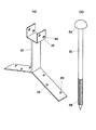
図5(a)に梁支持柱12を示す。この梁支持柱12は、屋根の棟の両側の勾配に対応した勾配を有する一対の脚部13を有し、この脚部20の頂部から立設した梁支持柱12の上端に、上向きに開いた正面コ字形の梁支持部18を有する。前記の脚部13には、同脚部13を屋根の野地板16に固定するための釘穴20が設けられている。また、梁支持柱12の上端の梁支持部18側壁にも棟瓦梁25を固定するための釘穴30が設けられている。
図5(b)は支持ピン21を示す。この支持ピン21は、大きな釘状のもので、頭部24は部分球形であり、先端部の周面には螺旋状の抜止29が刻設されている。
【0023】
図7は、屋根に葺かれる桟瓦17と、屋根の棟の上に葺かれる棟瓦の一部を示す。
和風の桟瓦17では、図示のような引掛桟瓦が使用されることが多い。図7では、桟瓦の下になっていて見えないが、桟瓦の図7において左上の瓦尻の下から屋根の瓦桟に引っ掛けるための突起が突設している。
【0024】
棟瓦は、少なくともかんむり瓦26を有し、洋風の場合は角形のかんむり瓦76のみが使用されることが多い。和風の場合は、いわゆる丸瓦と呼ばれる円筒形のかんむり瓦26が使用される。このかんむり瓦26は、円筒形の円筒部48一端側に円筒部の他端の外径より内径の太いソケット状の「ひも」と呼ばれる継手部分があり、この中に他のかんむり瓦26の他端を差し込んで接続するため、いわゆるひも付き丸瓦と呼ばれる。このかんむり瓦26の円筒部48の中央部には、釘を通す釘穴41が開設されている。
【0025】
このかんむり瓦の下に積まれる棟瓦は、面戸瓦やのし瓦22、23である。図7では面戸瓦は図示していない。下側に積まれるのし瓦22は1枚ののし瓦として使用され、上に積まれるのし瓦23は、縦に分割し、穴36に通した金属線等で互いに固定される。のし瓦22の端面には半円形の切欠35が設けられている。これは、前記棟瓦支持柱12を通すためのものである。
【0026】
次に、このような棟瓦支持部材及びかんむり瓦26等を使用して屋根の棟に棟瓦を構築する手順について説明する。
図1に示すように、一般的な木造建築の屋根の棟部では、いわゆる「棟木」と呼ばれる棟梁14が、いわゆる「つか」と呼ばれる図示してない小屋柱に支持された状態で架設されており、棟梁14と、その両側に架設された、いわゆる「母屋」と呼ばれる図示してない小屋梁との間に、いわゆる「たるき」と呼ばれる屋根梁15が、図1において紙面前後方向に所定の間隔で列んで架設されている。
【0027】
この屋根梁15の上には、板材からなる野地板16が張られ、さらに屋根の野地板16には、いわゆるルーフィングシートと呼ばれる防水シートが張られる。図示してはいないが、野地板16の頂部である棟の部分には、野地板16の間に隙間を開けておくか、或いは所々野地板16に開口部を開けておく。この隙間や開口部の幅は、前記棟瓦支持部材のフレーム本体1の幅より狭くする。
【0028】
図1に示すように、まず屋根の野地板16の頂部である棟に沿って、前記棟瓦支持部材を設置する。この設置に際しては、フレーム本体1の中央を野地板16の頂きである棟に位置合わせ、支持板2をその両側の野地板16の上に載せ、支持板2の釘穴10から野地板16を通して屋根梁15に釘19を打ち込み、固定する。このようにして、フレーム本体1を棟に沿ってその長手方向に継ぎ合わせながら屋根の野地板16及び屋根梁15に固定する。
【0029】
このようにして棟瓦支持部材を屋根の棟の上に取り付けるに当たっては、図6に示すように、棟瓦支持部材を屋根の棟に沿って継ぎ合わせていく。このとき、継ぎ合わせるフレーム本体1の間に前記梁支持柱12を挿入し、この梁支持柱12を継ぎ合わせた一対のフレーム本体1の端部の切欠8(図4参照)の中に嵌め込む。図6に示されたように、一対の切欠8はフレーム本体1を継ぎ合わせることで、矩形の窓状の開口部となる。梁支持柱12の両側の脚部13をフレーム本体1の端部の切欠11からその外に出し、この脚部13を支持板2の端部から突出した突片7(図4参照)の上に載せる。脚部13もその釘穴20を通して野地板16やその下の屋根梁15に釘19を打ち込んで固定される(図1参照)。
【0030】
このようようにして棟瓦支持部材が屋根の棟に沿って順次長手方向に継ぎ合わせられると共に、梁支持柱12が一定の間隔でフレーム本体1の継ぎ目の切欠11から立設される。この梁支持柱12の梁支持部18には、棟瓦梁25が嵌め込まれ、架設される。この棟瓦梁25は、梁支持部18の側壁に設けた釘穴30から打ち込んだ釘により梁支持部18に固定される。
【0031】
なお、梁支持柱12は、梁支持部材の1つ毎の間隔ではなく、例えば棟支持部材の1つおきの継ぎ目に設置するというように、適宜その間隔を変更することができる。その場合に、フレーム本体1の継ぎ目の切欠8によって形成される矩形の穴には、図5(b)に示すような支持ピン21を打ち込み、これに棟瓦梁25を固定してもよい。
【0032】
次に、屋根の野地板16の上に桟瓦17を葺く。桟瓦17は、軒先、妻、下り棟等の変化のある部分には、軒先桟瓦、一文字桟瓦、けらば桟瓦等の特殊な形状の桟瓦が使用されるが、洋風屋根の平坦な勾配部分には、主として平のし瓦やスペイン丸瓦等の桟瓦が使用される。桟瓦17は、屋根の勾配に沿ってその上側に当たる尻部の下面から突設した突起を、野地板16の上に棟と平行に釘等で固定した角材からなる瓦桟42に引っ掛けながら、屋根の軒先側から屋根の勾配に沿って棟側へ、つまり下から上側へと順次重ね葺きされる。このために、前記瓦桟42は、この桟瓦17を葺く間隔毎に、屋根の勾配に沿って所定の間隔で平行に取り付けられる。
【0033】
図1では、棟に最も近い屋根の最上部の桟瓦17の一部を示しているが、屋根の最上部の桟瓦17は、瓦桟ではなく、梁支持柱のフレーム本体1の両側に形成された台状の高くなった桟部4に瓦尻の下方の突起を引っ掛けて葺く。従って、屋根の最上部では、桟部4、4が瓦桟に代わり、この部分には瓦桟42を設けることは不要となる。
【0034】
なお、野地板16の上に瓦桟42を設ける前に、屋根の棟及び瓦桟42と直交するよう、つまり屋根の勾配方向に長尺な薄板からなるスペーサ43を設け、このスペーサ43上に瓦桟42を設けるとよい。このスペーサ43は、棟及び瓦桟42と直交する方向に間隔をおいて平行に設ける。瓦桟42をスペーサ43の厚み分だけ野地板16の上面から離して取り付けることにより、野地板16の上面での屋根の勾配に沿った流排水を円滑にすることができる。
【0035】
次に、桟瓦17及び棟瓦支持部材のフレーム本体1の上に棟瓦を積み上げる。例えば、面戸瓦、のし瓦22、23及びかんむり瓦26を棟の長手方向に継ぎ合わせながら積み上げて、棟瓦を構築する。
例えば、前記棟瓦支持部材のフレーム本体1の両側に一対の面戸瓦を取り付けるが、図示の例では面戸瓦は使用されていないため、棟瓦支持部材のフレーム本体1のとその両側の桟瓦17にわたって、中央部で分割されていない一体ののし瓦22を乗せる。
【0036】
棟に沿って複数ののし瓦22の端部を付き合わせて継ぎ合わせながら、屋根の棟に沿ってのし瓦22を葺いていく。このとき、棟瓦支持柱12がのし瓦22の切欠35の位置になるようにあらかじめのし瓦22の設置位置を調整しておく。次に、前記のし瓦22の上に、中央部を帯状に除去して2つ割りにした左右一対ののし瓦23、23を乗せる。このようにして中央部を帯状に除去して2つ割にした左右一対ののし瓦23、23を乗せるのは、下ののし瓦22より上ののし瓦23、23の設置幅を狭くするためである。なお、こののし瓦23、23の長さは、その下ののし瓦22と同じである。
【0037】
こののし瓦23、23もまた、棟に沿って端部を付き合わせて継ぎ合わせながら、順次複数組のものをのし瓦22の上に積み上げて行くが、上ののし瓦23、23と下ののし瓦22は、端部の突き合わせ位置が、のし瓦22、23の長さの半分だけずれるように継ぎ合わせながら積み重ねる。
【0038】
このようにしてのし瓦23、23をのし瓦22の上面の所定の位置に乗せた状態で、図1に示すように、のし瓦23、23の中間部の対向する部分に設けた穴36に銅線等の金属線を通し、一対ずつののし瓦23、23を結束し、互いに固定する。梁支持柱12は、分割したのし瓦23,23の間から突設される。
【0039】
なお、図1では、一体ののし瓦22を1段、分割したのし瓦23、23を1段重ね、合計2段ののし瓦22、23を積み重ねているが、のし瓦22が1段だけ積み重ねられ、分割したのし瓦23、23を積み重ねない場合もある。反対に、分割したのし瓦23、23を3段以上積み重ねる場合もある。この場合は、上にいくに従って、のし瓦の設置幅が狭くなるように重ねていく。さらに、のし瓦22の下に面戸瓦を積むことも多い。
【0040】
またこれらのし瓦22、23を葺くのと前後して、梁支持柱12の上端の梁受支持部18に角材等からなる棟瓦梁25を嵌め込み、梁支持部18の側面の釘穴30から釘を打ち込んで固定する。これにより、棟瓦梁25をのし瓦23、23の間の上に水平になるように架設する。
【0041】
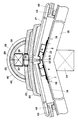
最後にのし瓦23の上にかんむり瓦26を乗せ、図1に示すように、その円筒部48の中央部が棟瓦梁25の上にほぼ乗る状態とする。かんむり瓦26は、紐部40を隣接する他のかんむり瓦26の円筒部48の端部に重ねて継ぎ合わせながら、棟瓦梁25に被せるようにし、両側ののし瓦23の上に葺いていく。
【0042】
このようにして葺いたかんむり瓦26は、図1に示すように、かんむり瓦26の円筒部48の中央に設けた釘穴41から釘28を棟瓦梁25に打ち込み、かんむり瓦26を棟瓦梁25に固定する。これによって、最も下の桟瓦17がその瓦尻の下方の突起をフレーム本体1の桟部4に嵌め込んで固定されるだけでなく、最も上の棟瓦であるかんむり瓦26がフレーム本体1から立設された梁支持柱12に架設された棟瓦梁25に固定される。これにより、地震等による振動に対して、棟瓦がずれず、ましては崩れることがない。
【0043】
さらに、この棟の部分で、野地板16の下の小屋裏と外部との間の高い防水性を保持したまま、その間の通気が桟瓦17の下から棟瓦支持部材の桟部4の通気窓6及びフレーム本体1の側壁の通気窓6を介して確保されるので、小屋裏の最も高い位置での換気性が確保される。
しかも、屋根の棟に沿って棟瓦支持部材を取り付けさせすれば、その後は面戸瓦、のし瓦22、23及びかんむり瓦26等を順次積み重ねていけばよいので、施工性もよく、容易に棟作りが行える。
【0044】
次に、図8〜図13に示した本発明の第二の実施の形態について説明する。
図8に瓦支持部材を使用した棟瓦を示し、図9〜図13に棟瓦支持部材及びその構成部材を示す。この棟瓦支持部材は、アルミニウム、ステンレス、亜鉛引き鉄板、トタン板等の耐食性を有するか或いは耐食処理を施した金属、或いは樹脂等により作られる。その構成部材は、大きく分けて、フレーム本体1とそれから立設される梁支持柱12(図5(a)参照)、支持ピン21(図5(b)参照)からなる。
【0045】
このフレーム本体1は後述するように、屋根の棟に沿って長手方向に継ぎ合わせて設置されるが、その長さは特に限定はない。これは前述の実施形態による棟瓦支持部材と同様である。
図10はフレーム本体1の正面を、図11はフレーム本体1の一端側の一部を、図12はフレーム本体1の他端側の一部を示している。図10に示すように、フレーム本体1及びその付属部材は両側において対称となっている。
【0046】
このフレーム本体1は、ステンレス板等の金属板を正面5角形状に形成したもので、底面には板材は無く、その全体が開いている。頂部の両側の上面の勾配は、設置する屋根の棟の両側の勾配とほぼ同じである。
図11に示すように、フレーム本体1の一端の上部両側の角部内側面に、同角部と同じ角度で曲げられた金属板からなる正面L字形の金属板が溶接等の手段で固着され、この金属板が継手片9としてフレーム本体1の一端から突設されている。さらに、フレーム本体1の一端の頂部には、切欠8が設けられている。
【0047】
図12は、フレーム本体1の他端を示しているが、このフレーム本体1の他端には前記のような継手片9は設けられていない。他方、フレーム本体1の他端の頂部には、前記フレーム本体1の一端側の切欠8と対応して同様の切欠8が設けられてがる。
【0048】
さらに、フレーム本体1の下部両側の角部に正面L字形の長尺な邪魔板3が固着され、この邪魔板3の縦の部分がフレーム本体1の内側面と間隔をおいて平行に対向している。この邪魔板3はフレーム本体1の全長にわたって設けられている。
【0049】
フレーム本体1の側壁には、後述する桟部4に設けられる通気窓6と同様の横に長い矩形の通気窓6が一定の間隔で開設されている。前記邪魔板3の縦の部分は、この通気窓6の内側にあって対向している。
図11及び図12に示す通り、フレーム本体1の端部には、その両側壁の下部に切欠11が設けられている。この切欠11の深さは、フレーム本体1の端部の頂部に設けた切欠8と同じ深さである。
【0050】
フレーム本体1の下部両側から外側に向けて一体に支持板2、2が延設されている。この支持板2、2は、両外側部へいくに従って下方に傾斜するような勾配が形成され、この勾配はフレーム本体1を設置する屋根の棟の両側の勾配と等しい。図11に示すように、フレーム本体1の一端において、前記両側の支持板2、2のそれぞれ2個所から、一体の金属片からなる突片7が突設されている。これら突片7の先端縁とフレーム本体1の先端縁とはほぼ面一である。
【0051】
図10〜図12に示すように、支持板2の上に長尺な正面L字形のステンレス板等が固着され、これによってフレーム本体1と平行に立設された桟部4が立設されている。図示の桟部4は、両側に一定の間隔で3つずつ立設されているが、この数は任意であってよい。但しその間隔は、後述する桟瓦17の瓦尻の下面の引き掛け用の突起の幅より広くする。従って、桟部4を多く立設する場合は、その分だけ支持板2の幅を広くする必要がある。支持板2の幅を広くすることは、棟瓦支持部材の全体の重量等も増すため、施工性が劣化するので、自ずと限度があり、図示のように両側の支持板2にそれぞれ2ないしは3つ程度の桟部4を設けるのが適当である。
【0052】
桟部4には、前記フレーム本体1の側壁に設けられたのと同様の横に長い矩形の複数の通気窓6が一定の間隔で開設されている。これら桟部4とフレーム本体1の通気窓6の幅と、それらの隣接する通気窓6の間隙の幅は同じであり、且つ隣接する桟部4及びフレーム本体1の側壁に設けられた通気窓は、交互にフレーム本体1及び桟部4の長手方向に1間隔分ずつずれている。
さらに、支持板2、2の桟部4の間の適当な位置に、支持板2を釘で屋根の野地板16に固定するための釘穴10が設けられている。
【0053】
この棟瓦支持部材を使用して屋根の棟にそって棟瓦を施工するのに使用された梁支持柱12や支持ピン21は、図5(a)、(b)にそれぞれ示したものと同様である。また、屋根に葺かれる桟瓦17や棟瓦も図7に示したものと同様である。これらの詳細は前述した通りである。
【0054】
次に、このような棟瓦支持部材及びかんむり瓦26等を使用して屋根の棟に棟瓦を構築する手順について説明する。
図8に示すように、まず屋根の野地板16の頂部である棟に沿って、前記棟瓦支持部材を設置する。この設置に際しては、フレーム本体1の中央を野地板16の頂きである棟に位置合わせ、支持板2をその両側の野地板16の上に載せ、支持板2の釘穴10から野地板16を通して屋根梁15に釘19を打ち込み、固定する。このようにして、フレーム本体1を棟に沿ってその長手方向に継ぎ合わせながら屋根の野地板16及び屋根梁15に固定する。
【0055】
このようにして棟瓦支持部材を屋根の棟の上に取り付けるに当たっては、図13に示すように、棟瓦支持部材を屋根の棟に沿って継ぎ合わせていく。このとき、フレーム本体1の一端から突設された継手片9(図11参照)を継ぎ合わせる他の棟瓦支持部材のフレーム本体1の他端(図12参照)に嵌め込んで継ぎ合わせる。
【0056】
このとき、継ぎ合わせるフレーム本体1の間に前記梁支持柱12を挿入し、この梁支持柱12を継ぎ合わせた一対のフレーム本体1の端部の切欠8(図11及び図12参照)の中に嵌め込む。図13に示されたように、一対の切欠8はフレーム本体1を継ぎ合わせることで、矩形の窓状の開口部となる。梁支持柱12の両側の脚部13をフレーム本体1の端部の切欠11からその外に出し、この脚部13を支持板2の端部から突出した突片7(図11及び図12参照)の上に載せる。脚部13もその釘穴20を通して野地板16やその下の屋根梁15(図8参照)に釘を打ち込んで固定される。
【0057】
このようようにして棟瓦支持部材が屋根の棟に沿って順次長手方向に継ぎ合わせられると共に、梁支持柱12が一定の間隔でフレーム本体1の継ぎ目の切欠11から立設される。この梁支持柱12の梁支持部18には、棟瓦梁25が嵌め込まれ、架設される。この棟瓦梁25は、梁支持部18の側壁に設けた釘穴30から打ち込んだ釘により梁支持部18に固定される。
【0058】
次に、屋根の野地板16の上に桟瓦17を葺く。図8では、棟に最も近い屋根の最上部の桟瓦17の一部を示しているが、屋根の最上部の桟瓦17は、瓦桟ではなく、梁支持柱の支持板2から突設された桟部4の何れかに瓦尻の下方の突起を引っ掛けて葺く。従って、屋根の最上部では、桟部4が瓦桟に代わり、この部分には瓦桟を設けることは不要となる。また桟部4が図8のように間隔をおいて複数あると、最上部の桟瓦17の位置を調整して葺くことができる。
【0059】
次に、桟瓦17及び棟瓦支持部材のフレーム本体1の上に棟瓦を積み上げる。例えば、面戸瓦、のし瓦22、23及びかんむり瓦26を棟の長手方向に継ぎ合わせながら積み上げて、棟瓦を構築する。これらの具体的な施工手段は、図1〜図7により前述した実施形態のものと同様であり、同様にして施工の容易性、強度、通気性等が得られる。
【0060】
次に、図14〜図20を参照しながら、本発明の他の実施の形態について説明する。
これらの実施形態は、図1〜図7により前述した棟瓦において、棟の上に梁支持柱12を立設し、これに棟瓦梁25を架設するのに代えて、棟瓦支持部材の上に、棟瓦支持フレーム51を立設したものである。洋風のかんむり瓦76をふくのに好適な実施形態である。
【0061】
図14に棟瓦支持フレーム51を使用した棟瓦を示し、図15〜図18及び図20に棟瓦支持フレーム51を示す。この棟瓦支持フレーム51は、アルミニウム、ステンレス、亜鉛引き鉄板、トタン板等の耐食性を有するか或いは耐食処理を施した金属、或いは樹脂等により作られる。棟瓦支持フレーム51は、正面がコ字形のチャンネル形状を有する長尺な金属部材からなるフレーム本体52と、そのの上に搭載される棟覆い部材56とからなる。
この棟瓦支持フレーム51は後述するように、屋根の棟に沿って長手方向に継ぎ合わせて設置されるが、その長さは、その下に設置される棟瓦支持部材の長さに準じる。
【0062】
前記フレーム本体52は、その一対の平行な側板の間に正面矩形のリング状のスペーサ54を挟持し、溶接等で固定したものである。従って、フレーム本体52の対向する一対の側壁2の間は、スペーサ54がある部分を除いて空間となっており、上下に通気性を有する。フレーム本体52の上縁部81はスペーサ54より高く延びている。他方、フレーム本体52の底壁60には、前述した棟瓦支持部材のフレーム本体1の中央部の通気窓6と同じ間隔で同じ大きさの通気窓(図示せず)が設けられている。
【0063】
前記スペーサ54の上下両壁には、棟瓦支持フレーム51の長手方向と直交する方向に対向するように貫通孔が設けられている。フレーム本体52の一対の側板を左右に水平に配置し、且つ棟瓦支持フレーム51の長手方向を水平に配置したとき、前記の貫通孔は、垂直に対向するように配置される。これら貫通孔は、後述するねじ74の径より僅かに大きく、スペーサ54の下側の壁部の上面には、その貫通孔と中心軸が一致するようにナット83が固着されている。
【0064】
フレーム本体52には、図20に示されたようなアタッチメント87が必要に応じて使用される。このアタッチメント87は、フレーム本体52と同じ長さを有し、フレーム本体52と同様の材料で作られる。このアタッチメント87は、幅の異なる横コ字形を呈したチャンネル状の一対の部材88、89を、上下に固着して作られており、下方の幅の狭い部材88をフレーム本体52の側板の上縁部81の間に嵌め込むことができる。上側の部材89の幅は、フレーム本体52の側板の上縁部81の幅と同じである。
【0065】
アタッチメント87を構成する上下の部材88、89の貼り合わせた横壁は、図示していない矩形の通気口が開口しており、通気口の間の部分は、フレーム本体52のスペーサ54の位置と対応している。また、この通気口の間の部分には、フレーム本体52のスペーサ54の前記貫通孔に対応して、同様の貫通孔が設けれている。
【0066】
このアタッチメント87の下方の部材88をフレーム本体52の上縁部81の間に嵌め込むことにより、上側の部材89の高さだけ、フレーム本体52が実質的に高くなる。従って、このアタッチメント87は、フレーム本体52の高さが低いため、後述する棟覆い部材56の中央部の両側に適当な勾配を形成でけいない時に使用する。アタッチメント87は、必要に応じて2段以上を重ねて用いることもできる。
【0067】
前記棟フレーム本体52の上に棟覆い部材56が載せられる。図14、図15、図18及び図20に示すように、この棟覆い部材56は、フレーム本体52と同様のもので作られた同じ長さの部材である。
この棟覆い部材56は、左右対称の5組の板状部材からなっている。図14、図15及び図20は、これらの板状部材を組み上げた状態を示し、図18は、一部の板状部材を分解した状態を示す。
【0068】
上側の第一の板状部材53は、端面L字形を呈し、外側部が下方に垂下した邪魔板77となっている。この第一の板状部材53とほぼ平行に配置された第二の板状部材55は、端面クランク状を呈し、その外側部の上面が第一の板状部材53の邪魔板77に近い内側の下面に固着されている。第一と第二の板状部材の間に挿入された第三の板状部材は、その内側縁部が第一の板状部材53の内側縁部の下面に固着され、その外側縁部が、第二の板状部材55の外側の立上り壁部に近い上面に固着されている。第一、第二及び第三の板状部材53、55、57の内側縁部を固定する第四の板状部材は、側面L字形を呈し、その内側に折れ曲がった上端は、第一の板状部材53の内側縁部に固着された第二の板状部材84の内側縁部の下面に固定されている。また、この第四の板状部材の下端縁部は、第二の板状部材55の下方に折れ曲がった内側縁部に固着され、この第二の板状部材55の内側縁部と共に、棟覆い部材56の中央から下方に垂下する差込片82を形成している。さらに、第五の板状部材94は、第二の板状部材55の両側部の下面に設けられた端面L字形のもので、この第五の板状部材94と前記第二の板状部材55の外側を向いた側面との間に溝状の風圧板取付部98が形成される。
【0069】
図18に示すように、第一の板状部材53の両側部には、その上面の水を抜く水抜孔85が適当な間隔で穿孔されている。さらに、第一の板状部材53の両側側の上面であって、前記水抜孔85の外側と、第五の板状部材94の下面には、それらの長手方向に沿って、ゴム、発泡樹脂等の弾性体からなる弾性部材79、80がそれぞれ取り付けられている。
【0070】
このように、5対の板状部材53、55、57、84が左右対称に組み上げられた状態で、第一の板状部材53の内側縁部が、帯状の連結部材71により連結されている。この連結部材71は、その長手方向に沿って塑性的に湾曲できるようになっており、これによって左右の板状部材53、3、57、84は、適当な角度で互いに傾斜させることができる。通常は、図18に示すように、連結部材71で連結された棟覆い部材56の中央部が高く、両側が低くなるような勾配が形成されるよう、連結部材71で棟覆い部材56の両側を曲げた状態で使用する。この棟覆い部材56の前記連結部材71には、前記フレーム本体52のスペーサ54やアタッチメント87の貫通孔の位置に対応して、貫通孔が設けられている。
【0071】
棟覆い部材56の第一の板状部材53の両外側の邪魔板77が垂下した部分の内側、すなわち、棟覆い部材56の側面を形成する第二の板状部材55の外側の立上り壁に、同板状部材55の長手方向に間隔をおいて開口部である通気窓58が設けられている。また、この第二の板状部材55の立上り壁の内側の上面に接合した第三の板状部材57の両外側縁にも、開口部からなる通気窓62が設けられている。さらに、第四の板状部材84の第二と第三の板状部材55、57に固着された部分の間にも、開口部である通気窓70が設けられている。
【0072】
これら通気窓58、62、70と各板状部材53、55、57の間隙とを介して、棟覆い部材56の両側部、すなわち邪魔板77側から第四の板状部材84の間の空間に通じる空気の流通路が形成されている。内側と外側の通気窓58、62、70、すなわち、通気窓58と通気窓62及び通気窓62と通気窓70とは、それぞれ棟覆い部材56の長手方向に互いにずれるように配置されている。
【0073】
第二の板状部材55の両側の立上り壁に設けられた通気窓58には、蜂等の小さな昆虫が通れない程度の目の細かいメッシュやパンチングメタル等からなるスクリーン61が張られている。また、棟覆い部材56の中央部の第四の板状部材84に設けられた通気窓70にも、蜂等の小さな昆虫が通れない程度の目の細かいメッシュやパンチングメタル等からなるスクリーン92が張られている。
【0074】
前記の風圧板取付部98を形成する第五の板状部材94の先端辺部には、図17に示すように、その長手方向に所定の間隔で切欠きが形成され、この切欠きは排水部95となっている。この排水部95は、前記第二の板状部材55の立ち上がり壁に設けられた通気窓58に対し、棟覆い部材56の長手方向にずれた位置に設けられている。より具体的には、隣接する通気窓58の間に位置するよう排水部95が設けられている。
【0075】
図15〜図18に示すように、前記風圧板取付部98には、風圧板93が差し込んで取り付けられる。この風圧板93は、ステンレスやアルミニウム板等からなるもので、棟覆い部材56の1ユニット分の長さ、1/2ユニット分或いは1/3ユニット分の長さを有する長尺な板材である。1/2ユニット分或いは1/3ユニット分の長さを有する風圧板93は、1ユニット分の棟覆い部材56に2枚または3枚が縦に並べて取り付けられる。
【0076】
この風圧板93には、前記風圧板取付部98の排水部95の位置に対応して下辺側に切欠き状の凹部が形成され、これが排水部96となっている。風圧板93が風圧板取付部98に取り付けられた状態で、風圧板93の排水部96と風圧板取付部98の排水部95とが一致し、水抜き用の開口部が形成される。風圧板93の排水部96が形成された部分は、他の部分より高くなっており、この部分は風受け部97である。
【0077】
図16に示すように、棟覆い部材56の風圧板取付部98の溝幅は、風圧板93の厚さに比べて充分大きく、このため風圧板93は、風圧板取付部98内で或る程度自由に揺動できる。
図15及び図20に示すように、棟覆い部材56の両側が低くなるような勾配を形成した場合、図16に示すように、第二の板状部材55の立ち上がり壁も傾く。このため、風圧板93は、図16に二点鎖線で示すように、自重によって棟覆い部材56の両外側に傾いている。この状態では、風圧板93が風圧板取付部98の縁または邪魔板77に当たってそれ以上の傾きが止められる。また、この状態では、風圧板93が棟覆い部材56の第二の板状部材55の立ち上がり壁から離れ、そこに設けた通気窓58が開いている。
【0078】
他方、風圧板93が棟覆い部材56の両側から図16に矢印で示すように吹き込んでくる風の風圧を受け、その風圧が強くなると、風圧板93は起こされて、第二の板状部材55の立ち上がり壁に当接する。この状態では、風圧板93が第二の板状部材55の立ち上がり壁に設けた通気窓58が閉じられる。
【0079】
前記連結部材71の上に、棟瓦固定部材63が取り付けられる。この棟瓦固定部材63は、棟覆い部材56と同じ長さで、端面ヘ字形のベースから垂直に壁を立ち上げ、この壁の上端を内側に鈎状に曲げてフック状に形成したものである。この棟瓦固定部材63の前記連結部材71の上に載せられる部分には、連結部材71の貫通孔に対応して貫通孔が設けられている。
【0080】
この棟覆い部材56は、前記フレーム本体52の上面に中央を合わせて載せる。すなわち、棟覆い部材56の中央の差込片82を、支持フレーム本体52の側板の上縁部81の間に差し込んで支持する。この状態で、棟覆い部材56の両外側が下方になるようそれを中央部で曲げ、棟覆い部材56の中央から両側部分に勾配を形成する。棟覆い部材56の中央の連結部材71とその上の棟瓦固定部材63の貫通孔からねじ74を差し込み、このねじ74の先端をフレーム本体52のスペーサ54の上壁の貫通孔に差し込み、さらにスペーサ54の下壁のナット83にねじ込み、締め付ける。
【0081】
この状態では、フレーム本体52の側板の上縁部81の内側に棟覆い部材56の差込片82が係合させれるため、フレーム本体52と棟覆い部材56とは、互いに幅方向の位置が規制される。また、ねじ74によりフレーム本体52と棟覆い部材56との長手方向の移動も規制され、フレーム本体52と棟覆い部材56とは、完全に固定される。
【0082】
なお、フレーム本体52の上に、図20に示すようなアタッチメント87が取り付けられる場合、棟覆い部材56は、このアタッチメント87の上に取り付けられることは言うまでもない。この場合は、アタッチメント87の上側の部材89の間に棟覆い部材56の差込片82を係合させる。
【0083】
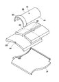
図19に、この棟瓦支持フレーム51を使用して屋根の棟の上に葺かれるかんむり瓦76を示す。このかんむり瓦76は、基本的に部分角筒形を呈した筒部を主体としており、この筒部の一方の端部には、筒部より一段高さが低い継手部90を有する。この継手部90を、他のかんむり瓦の端部に差し込むことにより、かんむり瓦が順次接続される。
【0084】
かんむり瓦76の筒部の中央には貫通孔91が設けられている。この貫通孔91には、フックねじ78の上端が嵌合される。このフックねじ78の下端は、鈎状に曲がっており、その上端にはねじが切られている。このねじが切られた上端には、リング状の弾性体からなるパッキン75が嵌め込まれ、さらにナット73がねじ込まれる。
【0085】
次に、前記のような棟瓦支持部材、棟瓦支持フレーム51及びかんむり瓦76を使用して屋根の棟に棟瓦を構築する手順について説明する。
図14に示すように、まず屋根の野地16の頂部である棟に沿って、前記棟瓦支持部材を設置する。この部分の工事は、基本的には図1〜図7に示した実施形態と同様であり、その詳細な説明は省略する。
【0086】
相違する点は、図1に示すように、屋根の棟に梁支持柱を立設する代わりに、棟瓦支持部材のフレーム本体1の中央部の平坦な部分に、前記の棟支持フレーム51のフレーム本体52の底面を載せて固定する。棟支持フレーム51の固定手段は、フレーム本体1の中央部の平坦な部分の底面に予め溶接等でナット83を固定しておき、これに棟覆い部材56をフレーム本体56を固定するためのボルト74の先端をねじ込んで、フレーム本体1、フレーム本体52及び棟覆い部材56を同時に固定する。あるいはフレーム本体52の底壁60をフレーム本体1の中央部の平坦な部分の上面に予め溶接してしまってもよい。このとき、棟瓦支持部材のフレーム本体1の中央部の通気窓6と前記の棟支持フレーム51のフレーム本体52の底壁60の通気窓とは一致させる。
【0087】
次に、棟覆い部材56をフレーム本体52の上面に中央を合わせて載せ、棟覆い部材56の中央の差込片82を、フレーム本体52の側板の上縁部81の間に差し込んで支持する。この状態で、棟覆い部材56の両外側が下方になるようそれを中央部で曲げ、桟瓦17の高さに応じて、棟覆い部材56の中央部から両側に適当な勾配を形成する。この状態では、前記棟覆い部材56の両外側部が最も上の桟瓦17の上に載せられ、その両側下面の弾性部材80が桟瓦17の上面に当たる。
【0088】
既に述べた通り、桟瓦17は、屋根の軒先側から上に葺き上げてくるため、棟に最も近い最上部では、桟瓦17の1枚分の長さに満たない長さで上下の桟瓦17の重ね合わせが調整される。このため、その調整量によっては、最上部の桟瓦17の上面の勾配が変わり、その高さが変わってくることがある。
【0089】
この場合、桟瓦17の上面が高くなり、前述のようにしてフレーム本体52の上に載せた棟覆い部材56の両側の勾配が緩くなりすぎてしまうことも起こり得る。それでは、棟覆い部材56の上面を伝わって雨水等が棟の方向に流れてしまうので、棟覆い部材56の取付高さを高くしなければならない。
そこでこのような場合は、図20に示すようなアタッチメント87を使用し、その上に棟覆い部材56を取り付けて、その取付高さを高くする。
【0090】
図14、図15、図18及び図19に示すように、棟覆い部材56の中央の連結部材71の上に棟瓦固定部材63を載せる。この棟瓦固定部材63及び連結部材71の貫通孔からボルト74を差し込み、このねじの先端をフレーム本体52のスペーサ54の上壁と下壁の貫通孔に差し込み、さらにボルト74の先端をフレーム本体1に固定したナット83にねじ込み、フレーム本体1の上にフレーム本体52と棟覆い部材56とを固定する。
次に、桟瓦17及び棟覆い部材56の上にかんむり瓦76を載せ、図14に示すように、その筒部の中央頂部を棟覆い部材56の中央部に位置合わせする。
【0091】
かんむり瓦76は、継手部90を隣接する他のかんむり瓦76の筒部の端部に挿入して継ぎ合わせながら葺いていく。この際、予め図14及び図19で示すように、フックねじ78の上端をかんむり瓦の貫通孔91に挿入しておく、そして、このフックねじ78の鈎状に曲がった下端を棟瓦覆い部材56の上に固定した棟瓦固定部材63の上縁のフック状に曲がった部分に掛ける。
【0092】
さらに、フックねじ78の上端のねじ部分にゴムリング等の弾性リング状のパッキン91を嵌め込み、その上からナット73をフックねじ78の上端にねじ込む。このナット73を締め込み、かんむり瓦76を棟瓦固定部材63を介して棟覆い部材56に固定する。このようにして、棟瓦が施工される。
【0093】
このような棟瓦では、棟の部分で、野地66の下の小屋裏と外部との間の高い防水性を保持したまま、その間の通気がフレーム本体52の通気窓3、棟覆い部材56の通気窓70及びその邪魔板57、58の間隙により確保されるので、小屋裏の最も高い位置での換気性が確保される。なお、かんむり瓦76と棟覆い部材6との間に吹き込んだ雨水は、第一の板状部材53の勾配にそってその両側部側に流れ、水抜孔85からその下の第二及び第三の板状部材55、57に流れ落ち、第二の板状部材55の通気窓8から風圧板93と風圧板取付部98の排水部95、96を通って棟覆い部材56の外側に流れ出す。
【0094】
また、棟覆い部材56の外側の風が弱いときは、風圧板93は、図16に二点鎖線で示すように傾いており、これによって最も外側の通気窓58が開かれ、前記のような棟覆い部材及びフレーム本体52の内部を通して、屋根の小屋裏の換気性が確保できる。これに対し、棟覆い部材56の側方から、図16に矢印示すように強い風が吹き込んできた場合、風圧板93が風圧を受け、図16に二点鎖線で示した角度から次第に通気窓58側に立ってくる。そして、ある程度の風速になると、風圧板93がその風圧を受け、図16に実線で示ように棟覆い部材56の側面に当接し、外側の通気窓58を閉じる。
【0095】
このようにして風圧板93で通気窓58が閉じられる風速は、風圧板93の重量、例えば板厚や幅等により設定できる。例えば、風圧板93として厚さ0.6mm、長さ965mm(1/2ユニット分の長さ)のステンレス板を使用した場合と、厚さ1.0mm、長さ965mm(1/2ユニット分の長さ)のアルミニウム板を使用した場合では、概ね同等の横風の風速で通気窓58を閉じることができた。具体的には、前記のようにして棟瓦を施工し、棟覆い部材56の側方から横風吹きつけて、次第にその風速を高めていって実験した結果では、前記のステンレス板及びアルミニウムの風圧板を使用した場合、いずれも風速19.4m/secで通気窓58が閉じられた。
このようにして、風が強くなると風圧板93で通気窓58が閉じられるようにしたことから、風雨が強いとき、雨水が通気窓58から棟覆い部材56の中に吹き込まれるのを防止することができる。
【0096】
また、前記のようにして棟瓦を施工するときは、屋根の棟に沿って棟瓦支持フレーム51と棟瓦梁75を取り付けさせすれば、その後は、それに沿ってかんむり瓦76を順次列べていけばよい。従って、施工性がよく、容易に棟作りが行われる。また、フレーム本体52と棟覆い部材56とにより、かんむり瓦76が固定されるので、地震等に対して高い強度の棟瓦を構築することができる。
【0097】
【発明の効果】
以上説明した通り、本発明による棟瓦支持部材とそれを使用して施工された棟瓦は、換気構造を有する棟瓦であったも、最も下に重ねられる最下段の瓦と最も上に重ねられる最上段の瓦とが棟に沿って設置された棟瓦支持部材にしっかりと固定されるので、高い耐震性と防水性を備える。しかも施工性に優れており、熟練した高い技能を有する技能者でなくても、容易に棟作りが行える。
【図面の簡単な説明】
【図1】本発明による棟瓦支持部材を使用して施工した棟瓦の例を示す屋根の棟部分の一部縦断正面図である。
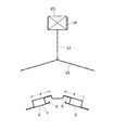
【図2】同棟瓦支持部材と梁支持柱の例を示す正面図である。
【図3】同棟瓦支持部材の正面図である。
【図4】同棟瓦支持部材の例を示すその一端部の斜視図である。
【図5】前記梁支持柱とそれに代えて棟に立設される支持ピンの斜視図である。
【図6】同梁支持柱を組み込んで前記棟瓦支持部材の端部を継ぎ合わせた状態の継合部の要部斜視図である。
【図7】本発明による棟瓦の例の瓦の構成を示す斜視図である。
【図8】本発明の他の実施形態による棟瓦支持部材を使用して施工した棟瓦の例を示す屋根の棟部分の一部縦断正面図である。
【図9】同棟瓦支持部材と梁支持柱の例を示す正面図である。
【図10】同棟瓦支持部材の正面図である。
【図11】同棟瓦支持部材の例を示すその一端部の斜視図である。
【図12】同棟瓦支持部材の例を示すその他端部の斜視図である。
【図13】前記梁支持柱を組み込んで同棟瓦支持部材の端部を継ぎ合わせた状態の継合部の要部斜視図である。
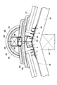
【図14】本発明の他の実施形態による棟瓦支持部材とその上に棟瓦支持フレームを搭載して施工した棟瓦の例を示す屋根の棟部分の一部縦断正面図である。
【図15】同棟瓦支持部材とその上に固定される棟瓦支持フレームの例を示す正面図である。
【図16】棟瓦支持部材の棟覆い部材の側部を示す要部拡大断面図である。
【図17】図16におけるA−A線矢視図である。
【図18】前記棟瓦支持部材の例を示す要部斜視図である。
【図19】棟瓦支持部材の上に固定される棟瓦であるかんむり瓦とそれを固定する棟瓦固定部材を示す分解斜視図である。
【図20】前記棟瓦支持部材、その上に固定される棟瓦支持フレーム及びそれに取り付けられるアタッチメントの例を示す縦断正面図である。
【符号の説明】
1 フレーム本体
2 支持板
3 邪魔板部
4 桟部
6 通気窓
8 切欠
9 継手
12 梁支持柱
16 野地板
17 桟瓦
21 支持ピン
22 のし瓦
23 のし瓦
25 棟瓦梁
26 かんむり瓦
51 棟瓦支持フレーム
76 かんむり瓦[0001]
BACKGROUND OF THE INVENTION
The present invention relates to a ridge tile support member for supporting a ridge tile obtained by laminating a roof tile and other tiles along a roof ridge, and a ridge tile spread along the roof ridge using the ridge tile support member. In particular, the present invention relates to a roof tile structure that improves all of ventilation, earthquake resistance, waterproofing and workability.
[0002]
[Prior art]
On the roof of tiled tiles, so-called ridges are made by joining tiled tiles along the ridges. A so-called Japanese-style tiled roof is constructed by sequentially stacking face door tiles, one or more layers of tile tiles, and kanmuri tiles (round tiles). On the other hand, the roof tiles are relatively simple for Western-style roofs. After rolling up the roof tiles from the eaves to the ridge along the roof gradient, the tile roof tiles are put together along the ridge, and the metal wire Just fix it with etc. A square-shaped roof tile is often used.
[0003]
[Problems to be solved by the invention]
In such a conventional roof tile, the waterproof property is almost perfect, but the overlapping portion of the roof tile may be displaced due to an earthquake or a strong wind. In particular, recent ceramic tiles tend to be lighter due to the roof structure. Conventional stacking of roof tiles causes the overlapping part to shift due to earthquakes, strong winds, etc., and if one sheet shifts, it spreads over a wide range one after another. To do. For this reason, there is a problem that the roof must be changed before the roof tiles are dropped or broken.
[0004]
In particular, today, the earthquake resistance of houses has been reviewed following the Great Hanshin-Awaji Earthquake. The earthquake resistance of the roof tiles is no exception and can be reviewed.
In addition, today's houses are highly airtight, especially in winter when the temperature difference between indoors and outdoors increases. As this adverse effect, dew condensation on the so-called hut behind the ceiling and roof is pointed out. Thereby, the necessity of ventilation in the ridge part which hits the uppermost part of a roof is pointed out.
In view of the problems in such a conventional ridge tile, the present invention aims to provide a ridge tile support member excellent not only in earthquake resistance, workability and ventilation, but also in waterproof properties and a ridge tile using the same. To do.
[0005]
[Means for Solving the Problems]
In the present invention, in order to achieve the above-mentioned object, a frame main body 1 having a space capable of venting is attached on the roof along the ridge, and the frame main body 1 is parallel to the frame main body 1 on both sides. A ventilation window 6 is provided on the crosspiece 4 and the side wall of the frame body 1. The crosspiece 4 also serves as a tile crossing, and hooks a protrusion projecting below the bottom of the roof tile 17 so as to spread the top roof tile 17 of the roof. Further, a beam support member is erected from the roof ridge or the frame body 1, and the ridge tile beam 25 is installed on the beam support member. Then, the ridge tile is placed over the frame main body 1 and the cross tiles 17 on both sides of the frame body 1, and the ridge tile pinning tile 26 is fixed to the ridge tile beam 25.
[0006]
That is, the ridge tile support member according to the present invention has a space that allows ventilation therein, and has a long frame body 1 that is attached to the roof along the top of the roof ridge. A plate-like support plate 2 provided on both sides of the roof ridge and fixed on the base plate 16 on both sides of the top of the roof ridge, and provided on both sides of the frame body 1 on the support plate 2Hook the bottom of the roof tile 17 that goes to the top of the roofIt has the elongate crosspiece part 4 which has a step part, and the ventilation window 6 each opened to this crosspiece part 4 and the side wall of the said frame main body 1, It is characterized by the above-mentioned.Further, a notch 8 for erecting a beam support column 12 for laying a ridge roof beam 25 or a nail-like support pin 21 is provided at the top of an end portion to be joined to another frame body 1 of the frame body 1.
[0007]
The ventilation windows 6 opened in the frame main body 1 and the crosspiece 4 are alternately displaced along the longitudinal direction of the frame main body 1 and the crosspiece 4 from the outside toward the center. Further, a baffle plate portion 3 is erected on the inner side of the ventilation window 6 on the side wall of the frame body 1 with a space.
[0008]
At the end of the frame body 1, there is a joint 9 for joining with other frame bodies 1 as necessary.Is provided.
The crosspiece 4 is formed by bending both sides of the frame main body 1 upward into a front rectangle or a panel-like one standing on the support plate 2. A plurality of the latter crosspieces 4 can be erected in parallel with each other.
[0009]
The ridge tile constructed using such a ridge tile support member attaches the frame main body 1 of the ridge tile support member on the roof along the top of the roof ridge, and supports the support plates 2 on both sides of the frame main body 1. The both sides of the roof ridge are fixed, the bottom of the roof tile 17 is hooked on the rail 4 and the top roof tile 17 of the roof is spread, and the frame body 1ofA tile support member is erected on the roof, and a ridge tile having at least the tile roof tiles 26 and 76 is placed over the frame body 1 and the roof tiles 17 extending on both sides thereof, and the tile roof tiles 26 and 78 are fixed to the roof tile support member. It is constructed by.
[0010]
The tile support member includes, for example, a beam support column 12 erected on the frame body 1 along the roof ridge, and a ridge tile beam 25 installed on the beam support column 12. The other roof tile support member includes a roof tile support frame 51 fixed on the frame body 1 from the center thereof.
In some cases, the ridge tile is composed only of the shingled tile 25, but at least one of the face tiles 22 and 23 is placed on the frame main body 1 and the cross tiles 17 spread on both sides thereof. A peeled tile 26 may be placed.
[0011]
In the ridge tile having such a structure, the roof ridge portion is covered with the frame body 1 and the support plates 2 on both sides thereof, but the frame body 1 is attached along the roof ridge and the support plates 2 on both sides thereof. Since the tile bottom of the roof tile 17 is hooked on the frame 4 standing upright and the top roof tile 17 of the roof is sown, it is not necessary to provide a roof tile on the top of the roof. Then, by setting up a plurality of the crosspieces 4 in parallel, even if the height of the topmost roof tiles 17 on the roof is slightly deviated, the height can be adjusted as needed.
[0012]
Furthermore, the ridged roof tile 26 spanned over the frame body 1 and the sills 17 on both sides of the frame body 1 is fixed to the ridge tile beam 25 erected on the beam support column 12 erected from the frame body 1. The upper roof tile 17 and the ridge tile are completely fixed, and the ridge tile that is difficult to collapse due to vibration such as an earthquake can be constructed.
[0013]
In addition, a ventilation window 6 is provided on the side wall of the crosspiece 4 and the frame body 1 and a space that allows ventilation is formed inside the long frame body 1 installed along the roof ridge. By providing a vent in the ridge portion that leads to the roof of the roof, natural ventilation of the roof can be performed through the ventilation window 6 and the internal space of the frame body 1.
[0014]
The ventilation window 6 is alternately shifted in the longitudinal direction of the crosspiece frame 4 and the frame main body 1 between the adjacent crosspiece frame 4 and the side wall of the frame main body 1. Intrusion into the interior of the is prevented. In addition, by providing the baffle plate portion 3 upright inside the ventilation window 6 on the side wall of the frame main body 1, it is possible to almost completely prevent rain water from entering the inside of the frame main body 1.
[0015]
DETAILED DESCRIPTION OF THE INVENTION
Next, embodiments of the present invention will be described specifically and in detail with reference to the drawings.
FIG. 1 shows a roof tile using a roof tile support member, and FIGS. 2 to 6 show a roof tile support member and its constituent members. This ridge tile support member is made of a corrosion-resistant metal such as aluminum, stainless steel, galvanized iron plate, tin plate or the like, or a resin or the like. The constituent members are roughly divided into a frame body 1, a beam support column 12 (see FIG. 6) and a support pin 21 (see FIG. 5) standing upright therefrom.
[0016]
As will be described later, the frame main body 1 is installed in the longitudinal direction along the roof ridge, but the length is not particularly limited. However, if one ridge tile support member is too long or too short, it is difficult to handle and the workability is inferior, so it is appropriate to use the length corresponding to the module of the building that covers the roof as a reference. For example, in the case of a conventional 903 mm (half-width) module, 1/3 of 303 mm (1 scale) and 2/3 of 606 mm (2 scale) are prepared as a reserve, based on the length of the roof tile support member. It is good to keep. Of course, in the case of a metric module, the length is basically 1000 mm.
FIG. 3 shows the front of the frame body 1 and FIG. 4 shows a part of one end side of the frame body 1. As shown in FIG. 3, the frame main body 1 and its attachment members are symmetrical on both sides.In these drawings, the underlined symbol “1” indicates the entire frame body, and the other symbols without the underline indicate each part of the frame body 1. Some of the signs indicate only one part that is symmetric on both sides, but this is merely an omission of the sign on the other part.
[0017]
The frame body 1 is formed by bending a metal plate such as a stainless steel plate in the thickness direction along the longitudinal direction, the center portion is low, the both sides thereof are bent upward, and the height is further increased. Both sides are lowered. The raised portions are the table-like crosspieces 4 and 4. A gradient is formed from the crosspieces 4 and 4 of the frame main body 1 to both sides thereof so as to become lower toward the side edges.
[0018]
A pair of plate-like support plates 2 and 2 are fixed to both lower sides of the frame body 1. The support plates 2 and 2 are fixed to the edge of the frame body 1 on the outside of the frame parts 4 and 4 of the frame body 1 by means of spot welding or the like, and above the frame parts 4 and 4 of the frame body 1. It is fixed to the lower surface via a long U-shaped spacer metal fitting 5.
[0019]
The support plate 2 has a slope that becomes lower toward both sides, and this slope is almost the same as the slope on both sides of the roof ridge. In the illustrated example, the slopes of the crosspieces 4 and 4 of the frame main body 1 are equal to the slopes of the support plates 2 and 2, so that the top surfaces of the crosspieces 4 and 4 and the top surface of the support plate 2 are parallel. Need not be parallel. The gradient of the support plate 2 is substantially the same as the gradient on both sides of the roof ridge, but the gradient of the crosspieces 4 and 4 is appropriately selected according to the shape of the roof tiles to be placed thereon.
[0020]
Near the lower sides of the support plates 2 and 2, several nail holes 10 for fixing the support plates 2 and 2 to the roof ridge are provided. On the other hand, the upper edge along the gradient of the support plate 2 is bent upward toward the frame body 1, and this portion is a front L-shaped baffle plate portion 3.
[0021]
On the upper wall of the frame main body 1 and the side walls on both sides thereof, rectangular ventilation windows 6 that are horizontally long are opened at regular intervals. Further, such a horizontally elongated rectangular ventilation window 6 is also provided on the vertical wall of the spacer metal fittings 5 and 5 that connect the frame main body 1 and the support plate 2 to the lower central portion of the frame main body 1. These ventilation windows 6 are provided at the same interval in the longitudinal direction of the frame body 1. The ventilation window 6 on the upper wall of the frame body 1, the ventilation window 6 on the side wall, the ventilation window 6 of the spacer fittings 5 and 5, and the ventilation window 6 in the center of the frame body 1 are alternately directed from the outside to the inside. The frame main body 1 and the support plates 2 and 2 are shifted in the longitudinal direction by one interval.
[0022]
FIG. 5A shows the beam support column 12. This beam support column 12 has a pair of legs 13 having a gradient corresponding to the gradients on both sides of the roof ridge, and opens upward at the upper end of the beam support column 12 erected from the top of the leg 20. And a front U-shaped beam support 18. The leg portion 13 is provided with a nail hole 20 for fixing the leg portion 13 to the roof base plate 16. Further, a nail hole 30 for fixing the ridge tile beam 25 is also provided on the side wall of the beam support 18 at the upper end of the beam support column 12.
FIG. 5B shows the support pin 21. The support pin 21 has a large nail shape, the head portion 24 has a partial spherical shape, and a spiral retaining member 29 is engraved on the peripheral surface of the tip portion.
[0023]
FIG. 7 shows a roof tile 17 to be laid on the roof and a part of the ridge tile to be laid on the roof ridge.
In the Japanese style roof tile 17, a hanging roof tile as illustrated is often used. In FIG. 7, although it is under the roof tile and cannot be seen, in FIG. 7 of the roof tile, a protrusion for hooking on the roof roof tile from the bottom of the upper left tile is protrudingly provided.
[0024]
The roof tile has at least the tile roof 26, and in the case of Western style, only the square roof tile 76 is often used. In the case of Japanese style, a cylindrical shaped roof tile 26 called a so-called round roof tile is used. The hollow tile 26 has a joint portion called a “string” having a larger inner diameter than the outer diameter of the other end of the cylindrical portion on one end side of the cylindrical cylindrical portion 48, and the other hollow tile 26 is included therein. Because the other end of the cable is inserted and connected, it is called a so-called stringed roof tile. A nail hole 41 through which a nail passes is formed in the central portion of the cylindrical portion 48 of the hollow tile 26.
[0025]
The roof tiles to be stacked under the roof tiles are the face door tiles and the roof tiles 22 and 23. In FIG. 7, the face tile is not shown. The roof tiles 22 stacked on the lower side are used as a single roof tile, and the roof tiles 23 stacked on the top are vertically divided and fixed to each other by metal wires or the like passed through the holes 36. A semicircular cutout 35 is provided on the end face of the roof tile 22. This is for passing the ridge tile support pillar 12.
[0026]
Next, a procedure for constructing a ridge tile in a roof ridge by using such a ridge tile support member and the curl tile 26 will be described.
As shown in FIG. 1, in a ridge portion of a general wooden building roof, a so-called “purlin” 14 is erected in a state of being supported by a so-called “tsuka” hut pillar (not shown). In addition, a roof beam 15 called “Taruki” between the ridge beam 14 and a hut beam (not shown) called “main building” erected on both sides of the building beam 14 in FIG. It is erected in rows at intervals.
[0027]
On the roof beam 15, a field board 16 made of a plate material is stretched, and a waterproof sheet called a roofing sheet is stretched on the roof field board 16. Although not shown in the figure, a gap is made between the field boards 16 in the ridge portion that is the top of the field board 16, or openings are opened in the field boards 16 in some places. The width of the gap and the opening is made narrower than the width of the frame body 1 of the ridge tile support member.
[0028]
As shown in FIG. 1, first, the ridge tile support member is installed along the ridge that is the top of the roof base plate 16. For this installation, the center of the frame body 1 is aligned with the ridge where the base plate 16 is received, the support plate 2 is placed on the base plate 16 on both sides thereof, and the base plate 16 is passed through the nail holes 10 of the support plate 2. A nail 19 is driven into the roof beam 15 and fixed. In this manner, the frame body 1 is fixed to the roof base plate 16 and the roof beam 15 while being joined together in the longitudinal direction along the ridge.
[0029]
When the ridge tile support member is mounted on the roof ridge in this way, the ridge tile support member is spliced along the roof ridge as shown in FIG. At this time, the beam support column 12 is inserted between the frame main bodies 1 to be joined, and the beam support columns 12 are fitted into the notches 8 (see FIG. 4) at the ends of the paired frame main bodies 1. . As shown in FIG. 6, the pair of cutouts 8 become rectangular window-shaped openings by joining the frame main bodies 1 together. The leg portions 13 on both sides of the beam support column 12 are projected out of the notch 11 at the end of the frame body 1, and the leg portion 13 is projected on the protruding piece 7 (see FIG. 4) protruding from the end of the support plate 2. Put it on. The leg 13 is also fixed by driving a nail 19 through the nail hole 20 into the base plate 16 and the roof beam 15 below (see FIG. 1).
[0030]
In this way, the roof tile support members are sequentially spliced in the longitudinal direction along the roof ridge, and the beam support columns 12 are erected from the joint notches 11 of the frame main body 1 at regular intervals. A roof tile beam 25 is fitted into the beam support portion 18 of the beam support column 12 and installed. The ridge roof beam 25 is fixed to the beam support portion 18 by a nail driven from a nail hole 30 provided on the side wall of the beam support portion 18.
[0031]
Note that the beam support columns 12 can be changed as appropriate, such as being installed at every other joint of the ridge support members, rather than every other beam support member. In that case, a support pin 21 as shown in FIG. 5B may be driven into a rectangular hole formed by the notch 8 of the joint of the frame body 1, and the ridge roof beam 25 may be fixed thereto.
[0032]
Next, the roof tile 17 is spread on the roof base plate 16. As for the roof tile 17, specially shaped roof tiles such as eaves roof tiles, single-character roof tiles, and kerak roof tiles are used for the changing parts such as eaves, wives, and downhills. In particular, flat roof tiles such as flat roof tiles and Spanish round tiles are used. The roof tile 17 is formed by hooking a protrusion projecting from the lower surface of the bottom part that hits the upper side of the roof along the slope of the roof onto a roof tile 42 made of square material fixed with a nail or the like on the field board 16 in parallel with the ridge. From the eaves side to the ridge side along the roof gradient, that is, from the bottom to the top, it is rolled up sequentially. For this purpose, the roof tiles 42 are attached in parallel at predetermined intervals along the roof gradient at every interval in which the roof tiles 17 are spread.
[0033]
In FIG. 1, a part of the topmost roof tile 17 of the roof closest to the ridge is shown, but the topmost roof tile 17 of the roof is not a tile rail but formed on both sides of the frame main body 1 of the beam support pillar. Hook the lower projection of the bottom of the roof tile on the pedestal 4 that has become a trapezoid. Therefore, in the uppermost part of the roof, the crosspieces 4 and 4 are replaced with the tiles, and it is not necessary to provide the tiles 42 in this portion.
[0034]
Before providing the roof tiles 42 on the field board 16, a spacer 43 made of a thin plate that is long in the direction of the roof gradient is provided so as to be orthogonal to the roof ridge and the roof tiles 42. It is good to provide the tile crossing 42. The spacers 43 are provided in parallel with an interval in a direction orthogonal to the ridge and the roof bar 42. By attaching the tile rail 42 away from the upper surface of the field plate 16 by the thickness of the spacer 43, the drainage along the roof gradient on the upper surface of the field plate 16 can be made smooth.
[0035]
Next, the roof tile is stacked on the frame body 1 of the roof tile 17 and the roof tile support member. For example, a roof tile is constructed by stacking face door tiles, roof tiles 22 and 23, and a tile tile 26 while joining them in the longitudinal direction of the building.
For example, although a pair of face roof tiles are attached to both sides of the frame main body 1 of the ridge tile support member, since the face roof tiles are not used in the illustrated example, the roof tiles 17 on the frame main body 1 of the ridge tile support member and on both sides thereof are used. A single roof tile 22 that is not divided at the center is placed.
[0036]
The roof tiles 22 are rubbed along the roof ridge while the ends of the plurality of roof tiles 22 are joined and joined together along the ridge. At this time, the installation position of the roof tile 22 is adjusted in advance so that the ridge tile support pillar 12 is positioned at the notch 35 of the roof tile 22. Next, on the roof tile 22, a pair of left and right roof tiles 23, 23 having the central portion removed in a strip shape and divided into two are placed. The pair of left and right roof tiles 23, 23 divided in half by removing the central portion in this way is placed on the installation width of the roof tiles 23, 23 above the lower roof tile 22. This is to make it narrower. The length of the roof tiles 23 and 23 is the same as the length of the roof tile 22 below.
[0037]
The roof tiles 23 and 23 are also piled up on the roof tile 22 in succession while joining the end portions along the ridge and joining them. The bottom roof tiles 22 are stacked while being joined so that the end butting positions are shifted by half the length of the roof tiles 22 and 23.
[0038]
As shown in FIG. 1, the roof tiles 23, 23 are provided at the opposite portions of the intermediate portions of the roof tiles 23, 23 as shown in FIG. A metal wire such as a copper wire is passed through the hole 36, and the pair of tiles 23 and 23 are bound and fixed to each other. The beam support column 12 protrudes from between the divided roof tiles 23 and 23.
[0039]
In FIG. 1, the integrated roof tiles 22 are stacked in one stage, the divided roof tiles 23 and 23 are stacked in one stage, and a total of two stages of roof tiles 22 and 23 are stacked. There is a case where only one stage is stacked and the divided roof tiles 23 and 23 are not stacked. On the contrary, the divided roof tiles 23 and 23 may be stacked in three or more stages. In this case, the tiles are stacked so that the installation width of the tiles becomes narrower as they go up. Furthermore, face tiles are often placed under the roof tiles 22.
[0040]
Further, before and after rolling these roof tiles 22 and 23, a roof tile beam 25 made of square or the like is fitted into the beam receiving support portion 18 at the upper end of the beam support column 12, and a nail hole 30 on the side surface of the beam support portion 18 is inserted. Drive in the nail and fix it. Thereby, the ridge tile beam 25 is installed so as to be horizontal between the tiles 23 and 23.
[0041]
Finally, the roof tile 26 is placed on the roof tile 23 so that the central portion of the cylindrical portion 48 is almost on the building tile beam 25 as shown in FIG. The roof tiles 26 are placed on the roof tile beams 25 while the string portions 40 are overlapped and joined to the ends of the cylindrical portions 48 of the other adjacent roof tiles 26, and the roof tiles 23 are placed on the roof tiles 23 on both sides. I will go.
[0042]
As shown in FIG. 1, the sooted roof tile 26 is driven into the ridge roof beam 25 from the nail hole 41 provided at the center of the cylindrical portion 48 of the roof tile 26, so that the roof tile 26 is Fix to the roof tile beam 25. As a result, the lowermost roof tile 17 is not only fixed by fitting the projection below the bottom of the roof tile into the rail section 4 of the frame body 1, but the upper tile roof tile 26 is removed from the frame body 1. It is fixed to a ridge tile beam 25 erected on the standing beam support column 12. This prevents the roof tiles from slipping or even collapsing against vibrations caused by earthquakes or the like.
[0043]
Further, in this ridge portion, while maintaining a high waterproof property between the back of the hut below the base plate 16 and the outside, the ventilation between them is from the bottom of the roof tile 17 to the ventilation window 6 of the bridge section 4 of the roof tile support member. And since it is ensured through the ventilation window 6 on the side wall of the frame body 1, the ventilation performance at the highest position on the back of the cabin is ensured.
Moreover, if the roof tile support members are attached along the roof ridge, then the face tiles, the tile roof tiles 22 and 23, the tile roof tiles 26, etc. can be stacked one after another. You can make a building.
[0044]
Next, a second embodiment of the present invention shown in FIGS. 8 to 13 will be described.
FIG. 8 shows a ridge tile using a tile support member, and FIGS. 9 to 13 show the ridge tile support member and its constituent members. This ridge tile support member is made of a corrosion-resistant metal such as aluminum, stainless steel, galvanized iron plate, tin plate or the like, or a resin or the like. The constituent members are roughly divided into a frame main body 1, a beam support column 12 (see FIG. 5 (a)) and a support pin 21 (see FIG. 5 (b)).
[0045]
As will be described later, the frame main body 1 is installed in the longitudinal direction along the roof ridge, but the length is not particularly limited. This is the same as the roof tile support member according to the above-described embodiment.
10 shows a front view of the frame body 1, FIG. 11 shows a part of one end side of the frame body 1, and FIG. 12 shows a part of the other end side of the frame body 1. As shown in FIG. 10, the frame main body 1 and its attachment members are symmetrical on both sides.
[0046]
The frame body 1 is formed by forming a metal plate such as a stainless steel plate into a front pentagonal shape, and there is no plate material on the bottom surface, and the whole is open. The slope of the top surface on both sides of the top is almost the same as the slope on both sides of the roof ridge to be installed.
As shown in FIG. 11, a front L-shaped metal plate made of a metal plate bent at the same angle as the corner portion is fixed to the inner side surface of the upper side of one end of the frame body 1 by means such as welding, This metal plate protrudes from one end of the frame body 1 as a joint piece 9. Further, a notch 8 is provided at the top of one end of the frame body 1.
[0047]
FIG. 12 shows the other end of the frame body 1, but the joint piece 9 as described above is not provided at the other end of the frame body 1. On the other hand, a similar notch 8 is provided at the top of the other end of the frame body 1 in correspondence with the notch 8 on one end side of the frame body 1.
[0048]
Furthermore, a long front L-shaped baffle plate 3 is fixed to the corners on both sides of the lower portion of the frame body 1, and the vertical portion of the baffle plate 3 faces the inner side surface of the frame body 1 in parallel with a gap. ing. The baffle plate 3 is provided over the entire length of the frame body 1.
[0049]
On the side wall of the frame body 1, rectangular long ventilation windows 6 are opened at regular intervals, similar to the ventilation windows 6 provided in the crosspiece 4 described later. The vertical part of the baffle plate 3 is located inside the ventilation window 6 and faces the ventilation window 6.
As shown in FIGS. 11 and 12, a cutout 11 is provided at the lower portion of both side walls of the end portion of the frame body 1. The depth of the notch 11 is the same depth as the notch 8 provided at the top of the end of the frame body 1.
[0050]
Support plates 2 and 2 are integrally extended outward from both lower sides of the frame body 1. The support plates 2, 2 are inclined so as to incline downward toward both outer portions, and this gradient is equal to the gradient on both sides of the roof ridge on which the frame body 1 is installed. As shown in FIG. 11, at one end of the frame body 1, projecting pieces 7 made of an integral metal piece project from two portions of the support plates 2 and 2 on both sides. The leading edges of the projecting pieces 7 and the leading edges of the frame body 1 are substantially flush.
[0051]
As shown in FIGS. 10 to 12, a long front L-shaped stainless steel plate or the like is fixed on the support plate 2, whereby the crosspiece 4 erected in parallel with the frame body 1 is erected. Yes. The illustrated crosspieces 4 are erected three by three at regular intervals on both sides, but this number may be arbitrary. However, the interval is made wider than the width of the hooking projection on the bottom surface of the bottom of the roof tile 17 to be described later. Therefore, when many crosspieces 4 are erected, it is necessary to increase the width of the support plate 2 accordingly. Increasing the width of the support plate 2 also increases the overall weight of the roof tile support member, which degrades the workability. Therefore, there is a limit naturally, and two or three support plates 2 on both sides as shown in the figure. It is appropriate to provide a cross section 4 of a degree.
[0052]
In the crosspiece 4, a plurality of horizontally long rectangular ventilation windows 6 similar to those provided on the side wall of the frame body 1 are opened at regular intervals. The widths of the crosspieces 4 and the ventilation windows 6 of the frame main body 1 are the same as the widths of the gaps between the adjacent ventilation windows 6 and the ventilation windows provided on the side walls of the adjacent crosspieces 4 and the frame main body 1. Are alternately shifted by one interval in the longitudinal direction of the frame body 1 and the crosspiece 4.
Further, a nail hole 10 for fixing the support plate 2 to the roof base plate 16 with a nail is provided at an appropriate position between the crosspieces 4 of the support plates 2 and 2.
[0053]
The beam support pillars 12 and the support pins 21 used to construct the roof tile along the roof ridge using this roof tile support member are the same as those shown in FIGS. 5 (a) and 5 (b), respectively. is there. The roof tiles 17 and the roof tiles that are laid on the roof are the same as those shown in FIG. These details are as described above.
[0054]
Next, a procedure for constructing a ridge tile in a roof ridge by using such a ridge tile support member and the curl tile 26 will be described.
As shown in FIG. 8, the ridge tile support member is first installed along the ridge that is the top of the roof base plate 16. For this installation, the center of the frame body 1 is aligned with the ridge where the base plate 16 is received, the support plate 2 is placed on the base plate 16 on both sides thereof, and the base plate 16 is passed through the nail holes 10 of the support plate 2. A nail 19 is driven into the roof beam 15 and fixed. In this manner, the frame body 1 is fixed to the roof base plate 16 and the roof beam 15 while being joined together in the longitudinal direction along the ridge.
[0055]
In attaching the ridge tile support member on the roof ridge in this way, the ridge tile support member is spliced along the roof ridge as shown in FIG. At this time, the joint piece 9 (see FIG. 11) projecting from one end of the frame body 1 is fitted and joined to the other end (see FIG. 12) of the frame body 1 of another roof tile support member.
[0056]
At this time, the beam support column 12 is inserted between the frame main bodies 1 to be joined, and the notches 8 (see FIGS. 11 and 12) at the ends of the pair of frame main bodies 1 to which the beam support columns 12 are joined. Fit into. As shown in FIG. 13, the pair of cutouts 8 become rectangular window-like openings by joining the frame main body 1 together. The leg portions 13 on both sides of the beam support column 12 are protruded outside from the notches 11 at the end of the frame body 1, and the projecting pieces 7 projecting from the end portions of the support plate 2 (see FIGS. 11 and 12). ). The leg 13 is also fixed by driving a nail through the nail hole 20 to the base plate 16 and the roof beam 15 (see FIG. 8) below the base plate 16.
[0057]
In this way, the roof tile support members are sequentially spliced in the longitudinal direction along the roof ridge, and the beam support columns 12 are erected from the joint notches 11 of the frame main body 1 at regular intervals. A roof tile beam 25 is fitted into the beam support portion 18 of the beam support column 12 and installed. The ridge roof beam 25 is fixed to the beam support portion 18 by a nail driven from a nail hole 30 provided on the side wall of the beam support portion 18.
[0058]
Next, the roof tile 17 is spread on the roof base plate 16. FIG. 8 shows a part of the topmost roof tile 17 of the roof closest to the ridge. However, the topmost roof tile 17 of the roof is not a tile rail but protrudes from the support plate 2 of the beam support column. Hook the lower protrusion of the tile bottom on any of the crosspieces 4 and spread it. Therefore, at the uppermost part of the roof, the crosspiece 4 is replaced with a tile cross, and it is not necessary to provide a tile cross at this portion. Further, when there are a plurality of crosspieces 4 at intervals as shown in FIG. 8, it is possible to adjust the position of the topmost roof tile 17.
[0059]
Next, the roof tile is stacked on the frame body 1 of the roof tile 17 and the roof tile support member. For example, a roof tile is constructed by stacking face door tiles, roof tiles 22 and 23, and a tile tile 26 while joining them in the longitudinal direction of the building. These specific construction means are the same as those of the embodiment described above with reference to FIGS. 1 to 7, and the ease of construction, strength, air permeability, and the like are obtained in the same manner.
[0060]
Next, another embodiment of the present invention will be described with reference to FIGS.
In these embodiments, in the ridge tile described above with reference to FIGS. 1 to 7, instead of erected the beam support pillar 12 on the ridge and erection the ridge tile beam 25 on this, on the ridge tile support member, A roof tile support frame 51 is erected. This is a preferred embodiment for wiping a Western style tile roof tile 76.
[0061]
FIG. 14 shows a roof tile using the roof tile support frame 51, and FIGS. 15 to 18 and 20 show the roof tile support frame 51. The ridge tile support frame 51 is made of a metal having a corrosion resistance such as aluminum, stainless steel, galvanized iron plate, tin plate or the like, a metal subjected to a corrosion resistance treatment, or a resin. The ridge tile support frame 51 includes a frame main body 52 made of a long metal member having a channel shape with a U-shaped front surface, and a ridge cover member 56 mounted thereon.
As will be described later, the ridge tile support frame 51 is installed along the roof ridge in the longitudinal direction. The length of the ridge tile support frame 51 conforms to the length of the ridge tile support member installed therebelow.
[0062]
The frame main body 52 has a front rectangular ring-shaped spacer 54 sandwiched between a pair of parallel side plates and is fixed by welding or the like. Therefore, the space between the pair of opposing side walls 2 of the frame main body 52 is a space except for the portion where the spacer 54 is present, and is vertically permeable. The upper edge 81 of the frame body 52 extends higher than the spacer 54. On the other hand, the bottom wall 60 of the frame body 52 is provided with ventilation windows (not shown) of the same size at the same interval as the ventilation window 6 at the center of the frame body 1 of the ridge tile support member described above.
[0063]
Through holes are provided in the upper and lower walls of the spacer 54 so as to face each other in a direction perpendicular to the longitudinal direction of the roof tile support frame 51. When the pair of side plates of the frame main body 52 are horizontally arranged on the left and right, and the longitudinal direction of the ridge tile support frame 51 is horizontally arranged, the through holes are arranged so as to face each other vertically. These through holes are slightly larger than the diameter of a screw 74 described later, and a nut 83 is fixed to the upper surface of the lower wall portion of the spacer 54 so that the through hole and the central axis coincide.
[0064]
An attachment 87 as shown in FIG. 20 is used for the frame main body 52 as required. The attachment 87 has the same length as the frame main body 52 and is made of the same material as the frame main body 52. This attachment 87 is formed by vertically adhering a pair of channel-shaped members 88 and 89 having horizontal U-shapes having different widths, and a lower narrow member 88 on the side plate of the frame main body 52. It can be fitted between the edges 81. The width of the upper member 89 is the same as the width of the upper edge portion 81 of the side plate of the frame main body 52.
[0065]
The lateral wall where the upper and lower members 88 and 89 constituting the attachment 87 are bonded has a rectangular ventilation hole (not shown), and the portion between the ventilation holes corresponds to the position of the spacer 54 of the frame main body 52. is doing. In addition, a similar through hole is provided in a portion between the vents corresponding to the through hole of the spacer 54 of the frame main body 52.
[0066]
By fitting the member 88 below the attachment 87 between the upper edge portions 81 of the frame main body 52, the frame main body 52 becomes substantially higher by the height of the upper member 89. Therefore, this attachment 87 is used when the frame main body 52 has a low height, so that an appropriate gradient cannot be formed on both sides of the central portion of the ridge covering member 56 described later. The attachment 87 can be used by overlapping two or more stages as necessary.
[0067]
A ridge covering member 56 is placed on the ridge frame main body 52. As shown in FIGS. 14, 15, 18, and 20, the ridge covering member 56 is a member of the same length made of the same material as the frame main body 52.
The ridge covering member 56 is composed of five symmetrical plate-like members. 14, FIG. 15 and FIG. 20 show a state in which these plate-like members are assembled, and FIG. 18 shows a state in which some plate-like members are disassembled.
[0068]
The upper first plate-like member 53 has an end face L-shape, and is a baffle plate 77 whose outer portion hangs downward. The second plate-like member 55 arranged substantially parallel to the first plate-like member 53 has an end face crank shape, and the upper surface of the outer portion thereof is an inner side close to the baffle plate 77 of the first plate-like member 53. It is fixed to the lower surface of the. The third plate-like member inserted between the first and second plate-like members has its inner edge fixed to the lower surface of the inner edge of the first plate-like member 53, and its outer edge is The second plate-like member 55 is fixed to the upper surface near the rising wall portion outside. The 4th plate-shaped member which fixes the inner edge part of the 1st, 2nd and 3rd plate-shaped members 53, 55, and 57 exhibits side L shape, and the upper end bent inside is the 1st plate The second plate-like member 84 fixed to the inner edge of the member 53 is fixed to the lower surface of the inner edge. The lower edge of the fourth plate-like member is fixed to the inner edge of the second plate-like member 55, and the ridge is covered together with the inner edge of the second plate-like member 55. An insertion piece 82 that hangs downward from the center of the member 56 is formed. Further, the fifth plate-like member 94 is an L-shaped end face provided on the lower surface of both side portions of the second plate-like member 55, and the fifth plate-like member 94 and the second plate-like member are provided. A groove-like wind pressure plate mounting portion 98 is formed between the side surface facing the outside of 55.
[0069]
As shown in FIG. 18, water drain holes 85 for draining water on the upper surface of the first plate-like member 53 are drilled at appropriate intervals. Further, on the upper surfaces on both sides of the first plate-like member 53, on the outside of the drain hole 85 and the lower surface of the fifth plate-like member 94, along the longitudinal direction thereof, rubber, foam resin Elastic members 79 and 80 made of an elastic body such as the like are respectively attached.
[0070]
In this way, the inner edge of the first plate member 53 is connected by the belt-like connecting member 71 in a state where the five pairs of plate members 53, 55, 57 and 84 are assembled symmetrically. . The connecting member 71 can be plastically bent along the longitudinal direction thereof, whereby the left and right plate-like members 53, 3, 57, 84 can be inclined with each other at an appropriate angle. Normally, as shown in FIG. 18, the connecting member 71 has both sides of the ridge covering member 56 so that a gradient is formed such that the central portion of the ridge covering member 56 connected by the connecting member 71 is high and both sides are low. Use in a bent state. The connecting member 71 of the ridge cover member 56 is provided with through holes corresponding to the positions of the spacers 54 of the frame main body 52 and the through holes of the attachment 87.
[0071]
On the inside of the portion where the baffle plates 77 on both outer sides of the first plate-like member 53 of the ridge cover member 56 hang down, that is, on the rising wall outside the second plate-like member 55 that forms the side surface of the ridge cover member 56. A ventilation window 58 as an opening is provided at intervals in the longitudinal direction of the plate-like member 55. Further, ventilation windows 62 each having an opening are provided on both outer edges of the third plate member 57 joined to the upper surface inside the rising wall of the second plate member 55. Further, a ventilation window 70 that is an opening is provided between portions of the fourth plate-like member 84 fixed to the second and third plate-like members 55 and 57.
[0072]
The space between both sides of the wing covering member 56, that is, the baffle plate 77 side to the fourth plate member 84, through the ventilation windows 58, 62, 70 and the gaps between the plate members 53, 55, 57. An air flow passage leading to is formed. The inner and outer ventilation windows 58, 62, 70, that is, the ventilation window 58 and the ventilation window 62, and the ventilation window 62 and the ventilation window 70 are arranged so as to be shifted from each other in the longitudinal direction of the ridge cover member 56.
[0073]
The ventilation window 58 provided on the rising wall on both sides of the second plate-like member 55 is stretched with a screen 61 made of a fine mesh or punching metal that does not allow small insects such as bees to pass through. In addition, a screen 92 made of fine mesh, punching metal, or the like that cannot allow small insects such as bees to pass through the ventilation window 70 provided in the fourth plate-shaped member 84 at the center of the ridge cover member 56. It is stretched.
[0074]
As shown in FIG. 17, notches are formed in the longitudinal direction of the fifth plate-like member 94 forming the wind pressure plate mounting portion 98 at predetermined intervals in the longitudinal direction. Part 95. The drainage portion 95 is provided at a position shifted in the longitudinal direction of the ridge cover member 56 with respect to the ventilation window 58 provided on the rising wall of the second plate member 55. More specifically, a drainage portion 95 is provided so as to be positioned between adjacent ventilation windows 58.
[0075]
As shown in FIGS. 15 to 18, a wind pressure plate 93 is inserted and attached to the wind pressure plate mounting portion 98. The wind pressure plate 93 is made of stainless steel, aluminum plate, or the like, and is a long plate material having a length corresponding to one unit, a half unit or a third unit of the ridge covering member 56. . Two or three wind pressure plates 93 each having a length corresponding to 1/2 unit or 1/3 unit are attached to a ridge covering member 56 corresponding to 1 unit in a line.
[0076]
In the wind pressure plate 93, a notch-shaped recess is formed on the lower side corresponding to the position of the drainage portion 95 of the wind pressure plate mounting portion 98, and this is the drainage portion 96. In a state where the wind pressure plate 93 is attached to the wind pressure plate attachment portion 98, the drainage portion 96 of the wind pressure plate 93 and the drainage portion 95 of the wind pressure plate attachment portion 98 coincide with each other to form an opening for draining water. The portion of the wind pressure plate 93 where the drainage portion 96 is formed is higher than the other portions, and this portion is the wind receiving portion 97.
[0077]
As shown in FIG. 16, the groove width of the wind pressure plate mounting portion 98 of the ridge cover member 56 is sufficiently larger than the thickness of the wind pressure plate 93, so that the wind pressure plate 93 is within the wind pressure plate mounting portion 98. It can swing freely.
As shown in FIGS. 15 and 20, when a slope is formed such that both sides of the ridge covering member 56 are lowered, the rising wall of the second plate-like member 55 is also inclined as shown in FIG. For this reason, the wind pressure plate 93 is inclined to both outer sides of the ridge covering member 56 by its own weight, as indicated by a two-dot chain line in FIG. In this state, the wind pressure plate 93 hits the edge of the wind pressure plate mounting portion 98 or the baffle plate 77 and the further inclination is stopped. In this state, the wind pressure plate 93 is separated from the rising wall of the second plate-like member 55 of the wing covering member 56, and the ventilation window 58 provided there is opened.
[0078]
On the other hand, when the wind pressure plate 93 receives the wind pressure of the wind blown from both sides of the wing covering member 56 as shown by the arrows in FIG. 16 and the wind pressure becomes stronger, the wind pressure plate 93 is raised and the second plate member 55 abuts against the rising wall. In this state, the ventilation window 58 provided with the wind pressure plate 93 on the rising wall of the second plate-like member 55 is closed.
[0079]
A roof tile fixing member 63 is attached on the connecting member 71. The ridge tile fixing member 63 has the same length as that of the ridge cover member 56, and is formed in a hook shape by vertically raising a wall from an end-face-shaped base and bending the upper end of the wall inwardly in a hook shape. . A through hole corresponding to the through hole of the connecting member 71 is provided in a portion of the roof tile fixing member 63 placed on the connecting member 71.
[0080]
The ridge covering member 56 is placed on the upper surface of the frame main body 52 with its center aligned. That is, the insertion piece 82 at the center of the ridge cover member 56 is inserted and supported between the upper edges 81 of the side plates of the support frame main body 52. In this state, the outer side of the ridge covering member 56 is bent at the center so that both outer sides are downward, and a gradient is formed from the center of the ridge covering member 56 to both side portions. A screw 74 is inserted from the through hole of the central connecting member 71 of the ridge cover member 56 and the ridge tile fixing member 63 above the ridge cover member 56, and the tip of the screw 74 is inserted into the through hole in the upper wall of the spacer 54 of the frame body 52. Screw into the nut 83 on the lower wall of 54 and tighten.
[0081]
In this state, the insertion piece 82 of the ridge cover member 56 is engaged with the inside of the upper edge portion 81 of the side plate of the frame main body 52, so that the frame main body 52 and the ridge cover member 56 are positioned in the width direction with respect to each other. Be regulated. Moreover, the movement of the frame main body 52 and the ridge covering member 56 in the longitudinal direction is restricted by the screw 74, and the frame main body 52 and the ridge covering member 56 are completely fixed.
[0082]
Needless to say, when an attachment 87 as shown in FIG. 20 is attached on the frame main body 52, the ridge covering member 56 is attached on the attachment 87. In this case, the insertion piece 82 of the ridge covering member 56 is engaged between the upper member 89 of the attachment 87.
[0083]
FIG. 19 shows a hollow tile 76 that is laid on the roof ridge using the ridge tile support frame 51. The chimney tile 76 mainly includes a cylindrical portion having a partial square cylindrical shape, and has a joint portion 90 that is one step lower than the cylindrical portion at one end portion of the cylindrical portion. By inserting this joint portion 90 into the end of another pin roof tile, the pin roof tiles are sequentially connected.
[0084]
A through-hole 91 is provided at the center of the cylindrical portion of the roof tile 76. The upper end of the hook screw 78 is fitted into the through hole 91. The lower end of the hook screw 78 is bent like a bowl, and the upper end is threaded. A packing 75 made of a ring-shaped elastic body is fitted into the upper end of the screw, and a nut 73 is further screwed.
[0085]
Next, a procedure for constructing a ridge tile in a roof ridge using the ridge tile support member, the ridge tile support frame 51, and the facing tile 76 will be described.
As shown in FIG. 14, first, the ridge tile support member is installed along the ridge that is the top of the roof field 16. The construction of this part is basically the same as that of the embodiment shown in FIGS. 1 to 7, and detailed description thereof will be omitted.
[0086]
The difference is that, as shown in FIG. 1, the frame of the ridge support frame 51 is arranged on the flat portion of the central portion of the frame main body 1 of the ridge tile support member instead of standing the beam support pillar on the roof ridge. The bottom surface of the main body 52 is placed and fixed. The ridge support frame 51 is fixed by fixing a nut 83 in advance to the bottom of the flat portion at the center of the frame body 1 by welding or the like, and a bolt for fixing the ridge cover member 56 to the frame body 56. The tip of 74 is screwed in, and the frame main body 1, the frame main body 52, and the ridge covering member 56 are fixed simultaneously. Alternatively, the bottom wall 60 of the frame body 52 may be previously welded to the upper surface of the flat portion at the center of the frame body 1. At this time, the ventilation window 6 at the center of the frame body 1 of the ridge tile support member and the ventilation window of the bottom wall 60 of the frame body 52 of the ridge support frame 51 are matched.
[0087]
Next, the ridge covering member 56 is placed on the upper surface of the frame main body 52 so that the center is aligned, and the insertion piece 82 at the center of the ridge covering member 56 is inserted and supported between the upper edge portions 81 of the side plates of the frame main body 52. . In this state, the ridge covering member 56 is bent at the center so that both outer sides are downward, and an appropriate gradient is formed on both sides from the center of the ridge covering member 56 according to the height of the roof tile 17. In this state, both outer side portions of the ridge covering member 56 are placed on the uppermost roof tile 17, and the elastic members 80 on the lower surfaces of both sides hit the upper surface of the roof tile 17.
[0088]
As already mentioned, since the roof tiles 17 are lifted up from the eaves side of the roof, the top and bottom roof tiles 17 have a length that is less than the length of one piece of the roof tiles 17 at the uppermost part closest to the building. The overlay is adjusted. For this reason, depending on the amount of adjustment, the slope of the upper surface of the topmost roof tile 17 may change and its height may change.
[0089]
In this case, the upper surface of the roof tile 17 becomes high, and the slopes on both sides of the ridge covering member 56 placed on the frame main body 52 as described above may become too loose. Then, since rainwater etc. will flow in the direction of a ridge along the upper surface of the ridge cover member 56, the installation height of the ridge cover member 56 must be made high.
Therefore, in such a case, an attachment 87 as shown in FIG. 20 is used, and a ridge covering member 56 is attached thereon to increase the attachment height.
[0090]
As shown in FIGS. 14, 15, 18, and 19, the roof tile fixing member 63 is placed on the connecting member 71 at the center of the roof covering member 56. Bolts 74 are inserted from the through holes of the roof tile fixing member 63 and the connecting member 71, the tips of the screws are inserted into the through holes of the upper wall and the lower wall of the spacer 54 of the frame main body 52, and the tips of the bolts 74 are inserted into the frame main body 1. Then, the frame body 52 and the wing covering member 56 are fixed on the frame body 1.
Next, the shingled tile 76 is placed on the roof tile 17 and the ridge covering member 56, and the central top portion of the cylindrical portion is aligned with the central portion of the ridge covering member 56 as shown in FIG. 14.
[0091]
The pin roof tile 76 is rolled while inserting the joint portion 90 into the end portion of the cylindrical portion of another adjacent pin roof tile 76 and joining them together. At this time, as shown in FIG. 14 and FIG. 19 in advance, the upper end of the hook screw 78 is inserted into the through hole 91 of the pinch tile, and the lower end of the hook screw 78 bent in a bowl shape is the roof tile covering member. It is hung on the bent portion of the upper edge of the roof tile fixing member 63 fixed on the hook 56 in a hook shape.
[0092]
Further, an elastic ring-shaped packing 91 such as a rubber ring is fitted into the screw portion at the upper end of the hook screw 78, and the nut 73 is screwed into the upper end of the hook screw 78 from above. The nut 73 is tightened, and the roof tile 76 is fixed to the building cover member 56 via the building tile fixing member 63. In this way, the roof tile is constructed.
[0093]
In such a ridge tile, the high ventilation between the back of the hut under the field 66 and the outside is maintained at the ridge portion, and the ventilation between them is the ventilation window 3 of the frame main body 52 and the ventilation of the ridge cover member 56. Since it is ensured by the gap between the window 70 and its baffle plates 57 and 58, ventilation is ensured at the highest position on the back of the cabin. The rainwater blown between the roof tile 76 and the ridge cover member 6 flows to the both side portions along the gradient of the first plate-like member 53, and the second and second portions below the drainage hole 85. It flows down to the third plate-like members 55 and 57, flows out from the ventilation window 8 of the second plate-like member 55 to the outside of the ridge cover member 56 through the wind pressure plate 93 and the drainage portions 95 and 96 of the wind pressure plate attachment portion 98.
[0094]
Further, when the wind outside the wing covering member 56 is weak, the wind pressure plate 93 is inclined as shown by a two-dot chain line in FIG. 16, thereby opening the outermost ventilation window 58, as described above. Through the inside of the ridge covering member and the frame main body 52, the ventilation of the roof of the roof can be secured. On the other hand, when strong wind blows in from the side of the wing covering member 56 as shown by the arrow in FIG. 16, the wind pressure plate 93 receives the wind pressure and gradually increases the ventilation window from the angle shown by the two-dot chain line in FIG. Stand on the 58th side. When the wind speed reaches a certain level, the wind pressure plate 93 receives the wind pressure, contacts the side surface of the ridge covering member 56 as shown by the solid line in FIG. 16, and closes the outer ventilation window 58.
[0095]
The wind speed at which the ventilation window 58 is closed by the wind pressure plate 93 in this way can be set by the weight of the wind pressure plate 93, for example, the plate thickness and width. For example, when a stainless steel plate having a thickness of 0.6 mm and a length of 965 mm (a length corresponding to 1/2 unit) is used as the wind pressure plate 93, a thickness of 1.0 mm and a length of 965 mm (a portion corresponding to 1/2 unit) In the case of using an aluminum plate having a length), the ventilation window 58 could be closed with substantially the same crosswind speed. Specifically, the roof tile was constructed as described above, and the wind was blown from the side of the ridge covering member 56, and the wind speed was gradually increased. As a result of the experiment, the stainless steel plate and the aluminum wind pressure plate were used. In each case, the ventilation window 58 was closed at a wind speed of 19.4 m / sec.
In this way, since the ventilation window 58 is closed by the wind pressure plate 93 when the wind becomes stronger, it is possible to prevent rainwater from being blown from the ventilation window 58 into the wing covering member 56 when the wind and rain are strong. Can do.
[0096]
In addition, when the ridge tile is constructed as described above, the ridge tile support frame 51 and the ridge tile beam 75 are attached along the roof ridge, and thereafter, the tile tiles 76 are sequentially arranged along the roof tile. That's fine. Therefore, the workability is good and building is easy. Moreover, since the pin roof tile 76 is fixed by the frame main body 52 and the ridge covering member 56, it is possible to construct a high strength ridge tile against an earthquake or the like.
[0097]
【The invention's effect】
As described above, the ridge tile support member according to the present invention and the ridge tile constructed by using the ridge tile support member are ridge tiles having a ventilation structure, but the bottom tile that is stacked at the bottom and the top tile that is stacked at the top. Because the roof tiles are firmly fixed to the roof tile support members installed along the tower, it has high earthquake resistance and water resistance. Moreover, it is excellent in workability and can be easily constructed even if it is not a skilled and highly skilled technician.
[Brief description of the drawings]
FIG. 1 is a partially longitudinal front view of a ridge portion of a roof showing an example of a ridge tile constructed using a ridge tile support member according to the present invention.
FIG. 2 is a front view showing an example of the same roof tile support member and beam support pillars.
FIG. 3 is a front view of the roof tile support member.
FIG. 4 is a perspective view of one end portion showing an example of the roof tile support member.
FIG. 5 is a perspective view of the beam support pillar and a support pin standing on the ridge instead.
FIG. 6 is a perspective view of a main part of a joining portion in a state where the beam supporting pillars are incorporated and ends of the ridge tile supporting members are joined together.
FIG. 7 is a perspective view showing the configuration of a roof tile as an example of a roof tile according to the present invention.
FIG. 8 is a partially longitudinal front view of a roof ridge portion showing an example of a ridge tile constructed using a ridge tile support member according to another embodiment of the present invention.
FIG. 9 is a front view showing an example of the same roof tile support member and beam support pillars.
FIG. 10 is a front view of the roof tile support member.
FIG. 11 is a perspective view of one end portion showing an example of the roof tile support member.
FIG. 12 is a perspective view of the other end showing an example of the roof tile support member.
FIG. 13 is a perspective view of a main part of a joining portion in a state where the beam supporting columns are incorporated and ends of the same roof tile supporting member are joined together.
FIG. 14 is a partial longitudinal sectional front view of a ridge portion of a roof showing an example of a ridge tile constructed by mounting a ridge tile support frame on the ridge tile support member according to another embodiment of the present invention.
FIG. 15 is a front view showing an example of the roof tile support member and a roof tile support frame fixed thereon.
FIG. 16 is an enlarged cross-sectional view of a main part showing a side portion of a ridge covering member of the ridge tile support member.
17 is a view taken along the line AA in FIG.
FIG. 18 is a main part perspective view showing an example of the ridge tile support member.
FIG. 19 is an exploded perspective view showing a roof tile that is a roof tile fixed on the roof tile support member and a roof tile fixing member that fixes the roof tile.
FIG. 20 is a longitudinal front view showing an example of the ridge tile support member, a ridge tile support frame fixed on the ridge tile support member, and an attachment attached thereto.
[Explanation of symbols]
1 Frame body
2 Support plate
3 Baffle plate
4 piers
6 Ventilation window
8 Notches
9 Fitting
12 Beam support column
16 Field board
17 Tile
21 Support pin
22 roof tiles
23 roof tiles
25 Building tile beams
26 Kanmuri Tile
51 Tile Support Frame
76 Kanmuri Tile