JP4050334B2 - Gas phase hydrogenation method - Google Patents
Gas phase hydrogenation method Download PDFInfo
- Publication number
- JP4050334B2 JP4050334B2 JP00080094A JP80094A JP4050334B2 JP 4050334 B2 JP4050334 B2 JP 4050334B2 JP 00080094 A JP00080094 A JP 00080094A JP 80094 A JP80094 A JP 80094A JP 4050334 B2 JP4050334 B2 JP 4050334B2
- Authority
- JP
- Japan
- Prior art keywords
- hydrogenation
- gas
- hydrogen
- catalyst
- stream
- Prior art date
- Legal status (The legal status is an assumption and is not a legal conclusion. Google has not performed a legal analysis and makes no representation as to the accuracy of the status listed.)
- Expired - Fee Related
Links
- ZQJNPHCQABYENK-UHFFFAOYSA-N COC(C(CC1)CCC1C(O)=O)=O Chemical compound COC(C(CC1)CCC1C(O)=O)=O ZQJNPHCQABYENK-UHFFFAOYSA-N 0.000 description 1
Images


Classifications
-
- C—CHEMISTRY; METALLURGY
- C07—ORGANIC CHEMISTRY
- C07C—ACYCLIC OR CARBOCYCLIC COMPOUNDS
- C07C29/00—Preparation of compounds having hydroxy or O-metal groups bound to a carbon atom not belonging to a six-membered aromatic ring
- C07C29/132—Preparation of compounds having hydroxy or O-metal groups bound to a carbon atom not belonging to a six-membered aromatic ring by reduction of an oxygen containing functional group
- C07C29/136—Preparation of compounds having hydroxy or O-metal groups bound to a carbon atom not belonging to a six-membered aromatic ring by reduction of an oxygen containing functional group of >C=O containing groups, e.g. —COOH
- C07C29/147—Preparation of compounds having hydroxy or O-metal groups bound to a carbon atom not belonging to a six-membered aromatic ring by reduction of an oxygen containing functional group of >C=O containing groups, e.g. —COOH of carboxylic acids or derivatives thereof
- C07C29/149—Preparation of compounds having hydroxy or O-metal groups bound to a carbon atom not belonging to a six-membered aromatic ring by reduction of an oxygen containing functional group of >C=O containing groups, e.g. —COOH of carboxylic acids or derivatives thereof with hydrogen or hydrogen-containing gases
-
- C—CHEMISTRY; METALLURGY
- C07—ORGANIC CHEMISTRY
- C07C—ACYCLIC OR CARBOCYCLIC COMPOUNDS
- C07C31/00—Saturated compounds having hydroxy or O-metal groups bound to acyclic carbon atoms
- C07C31/27—Polyhydroxylic alcohols containing saturated rings
- C07C31/272—Monocyclic
- C07C31/276—Monocyclic with a six-membered ring
-
- C—CHEMISTRY; METALLURGY
- C07—ORGANIC CHEMISTRY
- C07C—ACYCLIC OR CARBOCYCLIC COMPOUNDS
- C07C2601/00—Systems containing only non-condensed rings
- C07C2601/12—Systems containing only non-condensed rings with a six-membered ring
- C07C2601/14—The ring being saturated
-
- Y—GENERAL TAGGING OF NEW TECHNOLOGICAL DEVELOPMENTS; GENERAL TAGGING OF CROSS-SECTIONAL TECHNOLOGIES SPANNING OVER SEVERAL SECTIONS OF THE IPC; TECHNICAL SUBJECTS COVERED BY FORMER USPC CROSS-REFERENCE ART COLLECTIONS [XRACs] AND DIGESTS
- Y02—TECHNOLOGIES OR APPLICATIONS FOR MITIGATION OR ADAPTATION AGAINST CLIMATE CHANGE
- Y02P—CLIMATE CHANGE MITIGATION TECHNOLOGIES IN THE PRODUCTION OR PROCESSING OF GOODS
- Y02P20/00—Technologies relating to chemical industry
- Y02P20/50—Improvements relating to the production of bulk chemicals
- Y02P20/584—Recycling of catalysts
Abstract
Description
【0001】
【産業上の利用分野】
本発明は気相水素化方法に関する。
【0002】
【従来の技術】
不均一エステル水素化触媒の存在下でエステル、ジエステルおよびラクトンから選ばれる対応する不飽和有機化合物の水素化によってアルコールおよびジオールの製造に関する種々の方法が開示されている。このような不飽和有機化合物は−(CO)−O−結合中に炭素−酸素二重結合を有するという理由で不飽和である。これらの化合物はさらに不飽和結合を有する必要はない。すなわち、この型の水素化方法は、上記の炭素−酸素二重結合とは別に不飽和結合を含まない種々のエステル、ジエステルおよびラクトン、例えば、C8〜C22アルキルカルボン酸のモノエステル、C4〜C16ジカルボン酸のジエステル、および4〜16個の炭素原子を含むヒドロキシカルボン酸のラクトンなどに適用し得る。しかしながら、分子中にさらに存在する不飽和結合には及ばない。すなわち、このような方法は分子中にさらに不飽和結合を含むエステル、ジエステルおよびラクトン、例えば、C8〜C22脂肪族カルボン酸のモノエステル、不飽和脂肪族または脂環式カルボン酸のジエステルおよび不飽和ラクトンに用いることができる。
【0003】
このような水素化方法の例は、多くは従来液相で行われており、脂肪族モノカルボン酸のアルキルエステルからアルカノールへの水素化、脂肪族ジカルボン酸ジアルキルエステルから脂肪族ジオールへの水素化を含む。ある場合には、気相反応条件下で水素化反応を行うことが提案された。
【0004】
対応する環状脂肪族ジエステル、通常、それ自体が対応するベンゼンジカルボン酸ジアルキル、例えば、テレフタール酸ジメチルの水素化によって製造され得るシクロヘキサンジカルボン酸ジアルキルの水素化による環状脂肪族ジオール、シクロヘキサンジメタノールの製造が公知である。
【0005】
カルボン酸エステルの水素化触媒に用いられる市販の水素化触媒は、所望により、バリウムおよび/またはマンガンによって促進される銅クロマイトである。ブタン−1,4−ジオールの製造法でのこの触媒の使用がEP−A−0143634に開示されている。WO−A−82/03854において、酸化銅および酸化亜鉛の還元混合物を含む触媒を利用するカルボン酸の水素化分解を行う方法が開示されている。挙げられ得る水素化反応に利用し得る他の触媒はWO−A−89/00886のパラジウム/亜鉛含有触媒およびEP−A−0241760の混合触媒系である。マンガン促進銅触媒も水素化触媒として市販されている。
【0006】
水素化反応器は外部または内部冷却によって断熱的にまたは恒温的に操作される。断熱的反応器はシェル型または管状型の恒温反応器よりも建設および操作が容易であるために優れている場合は断熱的反応器が用いられる。
【0007】
エステル、ジエステルおよびラクトン供給原料の水素化は一般に発熱反応である。液相反応において、供給原料は通常は不活性希釈剤、好都合なことに再循環生成物ヒドロキシ化合物によって希釈され、触媒は全体的に液で濡れている。希釈は熱低下として働き、水素化反応の発熱性のために触媒を損なう危険性を妨げるために働く。
【0008】
典型的な気相水素化方法において、不飽和有機化合物、すなわち、エステル、ジエステルまたはラクトンは通常、加熱水素含有ガス中に直接気相化され、気相混合物となり、これはさらに加熱されるか、露点以上の温度に上げるため加熱水素含有ガスでさらに希釈される。通常は触媒と接触している気相混合物がその露点、すなわち、ガスの混合物と蒸気が霧または薄膜として結露する温度以上であることを確実にすることが重要である。この結露液は通常気相のすべての凝縮組成物および気体を通常の気相/液相臨界点を満足する濃度で溶解している。それは出発物質、中間体生成物、副産物および/または最終水素化生成物を含み得る。一般に、この方法は蒸気供給混合物の温度がその露点以上、例えば、露点以上約5℃〜約10℃高く操作される。さらに、触媒と液体の露滴、特に不飽和有機化合物に富む露滴との接触を妨げることが望ましい。なぜなら、触媒の劣化は、物理的強度の減少、触媒表面上または触媒孔中の熱スポット(hot spot)の形成、反応の発熱性のために焼結を導く可能性があり、そのために、化学的有効触媒表面(特に、銅含有触媒の場合に)の減少、ペレット孔内の爆発性蒸気の可能性の結果として触媒ペレットの崩壊に起因し得るからである。触媒表面上の熱スポットの形成のようなメカニズムによる水素化触媒の成熟減成を妨げるための水素化反応器の条件はWO−A−91/01961に開示されている。
【0009】
水素化触媒の寿命を最大化するために十分注意しても、なお、例えば、WO−A−91/01961に記載したように、水素化触媒が一般に確実に著しく不活性化され、時間の経過にともなって触媒的活性が不可逆的に減少し得る水素化範囲中の条件にさらされることが当分野では認められている。このような不活性化は異なる水素化反応における種々の理由のせいかもしれない。例えば、触媒表面上の炭素または炭素性物質の堆積は触媒活性の減少の原因になる。このような不活性化過程に加えて、触媒ペレットは時間の経過に従って物理的に崩壊し粉末化し、触媒床を通過する蒸気通路を遮断し、触媒床を通過する圧力低下の容認できない程度の増大を導く傾向がある。不活性化過程はゆるやかであるかもしれないが容易に可逆化しない。
【0010】
商業的水素化方法において、触媒は結局は活性および/または選択性を消失し、あらたな触媒の充填物で置換する必要がある。水素化反応における触媒不活性化の多くの無関係であるが補足的な理由が存在する。これらはi)触媒表面上の炭素性物質の堆積、ii)局部的な物理的条件からくる触媒ペレットの粉末化または構造的劣化、iii)触媒毒、特に塩素または硫黄を含む化合物によるもの、およびiv)に触媒が銅含有触媒であり、高温、例えば230℃をはるかに越える温度であるときの触媒の焼結である。
【0011】
銅含有触媒を用いる水素化反応では、触媒は、焼結のため(そう考えられている)および、金属の移動のために容易に不活性化され、また、触媒粒子が微細粉末に崩壊し物理的強度の減少につながることが当分野で一般に認められている。すなわち、銅含有水素化触媒の触媒不活性化は不可逆的であると考えられている。すなわち、例えば、US−A−3334149の示唆により、1,4−シクロヘキサンジカルボン酸ジメチルの液相水素化における長期使用の結果不活性化された銅含有触媒の再活性化の試みは成功しなかった。
【0012】
不活性化過程の逆転(reversible)または減速を可能にする水素化方法は触媒消費経費の低下故に当分野の公知の方法よりかなりの商業的利点を有するものと思われる。このような方法はさらに触媒回転率の減少をもたらす顕著な環境的利点をも有する。
【0013】
発明の要約
本発明の目的は従って、エステル、ジエステルおよびラクトンの水素化において、使用中の触媒活性が低下した後のエステル水素化触媒の再活性化方法の提供である。本発明のさらなる目的は、C8〜C22モノカルボン酸、ジカルボン酸ジエステルおよびラクトンから選ばれる不飽和有機化合物を水素化し、対応するアルコールまたはジオールを製造する方法であって、そこで使用される銅含有触媒の寿命を周期的な再活性化によって延命することを特徴とする方法である。
【0014】
【課題を解決するたの手段】
本発明は、エステル、ジエステルおよびラクトンから選ばれる対応する不飽和有機化合物の水素化によって、アルコールおよびジオールから選ばれるヒドロキシ化合物の製造方法であって、
(a)各々が不飽和化合物のヒドロキシ化合物への水素化を触媒するための有効な粒状水素化触媒の充填物を含む少なくとも2個の水素化ゾーンを設けること、
(b)少なくとも1個の水素化ゾーンに、操作の第1工程で水素含有ガスおよび不飽和有機化合物を含む気相供給流を供給すること、
(c)少なくとも1個の水素化ゾーンを、操作の第1工程で、不飽和有機化合物を水素化しヒドロキシ化合物を生成させる温度および圧力条件に維持すること、
(d)少なくとも1個の水素化ゾーンから、操作の第1工程で、ヒドロキシ化合物を含む反応生成物流を回収すること、
(e)少なくとも1個の他の水素化ゾーンに、操作の第1工程で、その中に含まれる水素化触媒の充填物を再活性化させる水素含有気体流を供給すること、
(f)少なくとも1個の他の水素化ゾーンに、操作の第2工程で、水素含有ガスおよび不飽和有機化合物を含む気相供給流を供給すること、
(g)少なくとも1個の他の水素化ゾーンを、操作の第2工程で、不飽和有機化合物を水素化しヒドロキシ化合物を生成させる温度および圧力条件に維持すること、
(h)少なくとも1個の他の水素化ゾーンから、操作の第2工程で、ヒドロキシ化合物を含む反応生成物流を回収すること、および
(i)少なくとも1個の水素化ゾーンに、操作の第2工程で、その中に含まれる水素化触媒の充填物を再活性化させる水素含有ガス流を供給すること
を含む方法を提供する。
【0015】
本発明の方法は、それぞれの水素化ゾーンでの供給温度でかなりの蒸気圧、例えば、約0.01psia(約0.001バール)を有して気体化できるいずれのエステル、ジエステルおよびラクトンの水素化を行うのにも利用することができ、この方法は触媒上に化学元素の炭素を堆積させない方法である。当業者に理解されるように、本発明はいかなる新規な水素化反応、またはいかなる新規な水素化条件、またはいかなる新規な触媒の発見に基づくものではないが、その代わり水素化プラントの機械的な配列および制御、およびプラント中に存在する2個またはそれ以上の水素化ゾーンを通過する物質の全体的な流れに関するものである。
【0016】
具体的には、エステル、ジエステルおよびラクトンは30個以上の炭素原子を含む。不飽和有機化合物は好ましくは例えば、C8〜C22アルキルカルボン酸のモノエステル、C4〜C16ジカルボン酸のジエステル、および4〜16個の炭素原子を含むヒドロキシカルボン酸のラクトン、およびC8〜C22脂肪族カルボン酸のモノエステル、不飽和脂肪族または脂環式カルボン酸のジエステルおよび不飽和ラクトンから選ばれる。
【0017】
エステル、ジエステルまたはラクトンの供給原料の使用を含む水素化反応の例は、これに対して本発明の示唆が適用され得るが、WO−A−91/01961、EP−A−014634、WO−A−86/03189およびWO−A−86/07358に開示された方法を含む。
【0018】
不飽和有機化合物は少なくとも4個の炭素原子を含むジカルボン酸のジ−(C1〜C4アルキル)エステルであってもよい。すなわち、好ましい一方法では、不飽和有機化合物は、例えば、C4ジカルボン酸のジアルキルエステルであり、例えば、マレイン酸ジアルキル、および対応する水素化生成物はブタン−1,4−ジオール、ガンマ−ブチロラクトンまたはテトラヒドロフランまたはそれらの1またはそれ以上の混合物である。このような方法において、銅含有触媒は好ましくは還元銅クロマイト触媒、還元促進銅クロマイト触媒、または還元マンガン促進銅触媒である。マレイン酸ジアルキルは通常はマレイン酸ジ−(C1〜C4)アルキルであり、好ましくはマレイン酸ジメチルまたはマレイン酸ジエチルである。
【0019】
同様の反応はブタン−1,4−ジオールを生成するガンマ−ブチロラクトンの水素化、またはヘキサン−1,6−ジオールを生成するイプシロン−カプロラクトンである。
【0020】
不飽和有機化合物はシクロヘキサンジカルボン酸ジ−(C1〜C4アルキル)であってもよく、例えば、シクロヘキサンジカルボン酸ジメチルであり、水素化生成物はシクロヘキサンジメタノールである。すなわち、特に好ましい方法では、不飽和有機化合物は1,4−シクロヘキサンジカルボン酸ジメチルであり、水素化生成物は1,4−シクロヘキサンジメタノールである。本発明の方法が適用し得る他の反応は、1,2−または1,3−シクロヘキサンジカルボン酸ジ−(C1〜C4アルキル)の水素化を含み、例えば、それぞれ1,2−または1,3−シクロヘキサンジカルボン酸ジメチルの1,2−または1,3−シクロヘキサンジメタノールへの水素化を含む。
【0021】
本発明の方法に出発物質として用いられ得る、他の型の不飽和有機化合物としてはエステルを挙げることができ、例えば、C8〜C22モノカルボン酸のC1〜C4アルキルエステルである。具体的なエステルにはC8〜C22アルキルカルボン酸のメチルまたはエチルエステルであり、ラウリル酸メチル、オレイン酸メチル、ステアリン酸メチル、リノール酸メチルなどである。
【0022】
本発明方法で用いられる粒状触媒は、エステルの対応するアルコールまたは混合物への水素化または水素化分解を触媒する作用を持つものであれば格他の制限はない。それは適当な形、例えばペレット、輪状または鞍型に成形されていてもよい。
【0023】
典型的な銅含有エステル水素化触媒には、アルミナ上銅触媒、還元酸化銅/酸化亜鉛触媒(必要に応じて促進剤(promoter)を伴う)、還元マンガン促進(promoted)銅触媒、還元銅クロマイト触媒(必要に応じて促進剤を伴う)などがある。適当な酸化銅/酸化亜鉛触媒前駆体としては、CuO/ZnO混合物を含んでおり、Cu:Zn重量比が、約0.4:1〜2:1であるものが含まれる。例として、DRD 92/71と呼ばれる触媒前駆体がある。促進酸化銅/酸化亜鉛前駆体は、CuO/ZnO混合物を含んでおり、そのCu:Zn重量比が、約0.4:1〜2:1の範囲のものであり、約0.1〜15重量%のバリウム、マンガンまたはバリウムとマンガンの混合物により促進される。このように促進CuO/ZnO混合物には、DRD 92/92の呼称で入手可能なMn−促進CuO/ZnO前駆体がある。適切な銅クロマイト触媒前駆体には、約0.1:1〜4:1、好ましくは約0.5:1〜4:1の範囲のCu:Cr重量比を持つものが含まれる。この型の触媒前駆体は、DRD 89/21またはPG 85/1なる呼称で入手可能である。適切な促進銅クロマイト前駆体は、約0.1:1〜4:1、好ましくは約0.5:1〜4:1の範囲のCu:Cr重量比を有するものが含まれ、約0.1〜15重量%のバリウム、マンガンまたはバリウムとマンガンの混合物により反応促進される。マンガン促進銅触媒前駆体は、典型的には、約2:1〜10:1のCu:Mn重量比を有しており、通常、約2:1〜4:1のCu:Al重量比となるようにアルミナ支持体を含有している。その具体例としては、触媒前駆体DRD 92/89がある。
【0024】
上記一般呼称DRDまたはPGを有する触媒は、全てイギリス、クリヴランド・TS18・3HA、ストックトン−オン−ティーズ、ボウスフィールド・レーン、P.O.Box 37のディビー・リサーチ・アンド・デベロップメント・リミテッドから入手することが出来る。
【0025】
本発明方法で使用される触媒の物理的支持体としては、支持体として知られているものを適宜に使用することが可能であり、そのような支持体は、酸化亜鉛、アルミナ、シリカ、アルミナ−シリカ、シリコンカーバイド、ジルコニア、チタニア、炭素、ゼオライト、またはそれらの適当な組合せなどの物質である。
【0026】
本発明の方法に使用するのに特に好ましい触媒は、上記した還元形の銅クロマイト、促進銅クロマイト、およびマンガン促進銅触媒前駆体である。
【0027】
本発明の方法の工程(e)および(i)において、水素化触媒のそれぞれの充填物はそれによって触媒充填物を再活性化させるための水素含有気体流で処理される。通常は、これらの工程を行うには温度を上昇させるのが好ましく、具体的には、約150℃〜それ以上約340℃である。これらの工程でのそれぞれの水素化ゾーン(複数であってもよい)への供給温度は、工程(b)および(f)の気相供給流の水素化ゾーンへの供給温度より、低くくてもよく、例えば、約10℃〜約50℃低いか、実質的に等しいか、または約10℃〜50℃より高くてもよい。再活性化工程(e)および(i)中の水素化ゾーンへの供給温度は、工程(b)および(f)中で用いられ気相の水素化ゾーンへの供給温度より、約10℃〜約30℃低いか、約10℃〜約30℃高くてもよい。
【0028】
工程(e)および(i)で用いられる水素含有ガス流は再循環ガスの熱流を含んでいてもよい。好都合には、少なくとも1個の(e)および(i)での水素含有ガス流は再循環および組合せ(make-up)ガスの熱流を含む。
【0029】
工程(e)および(i)中の供給圧は、工程(b)および(f)中で用いられる供給圧より、同じか、低いかまたは高くてもよい。好ましくは、それは工程(b)および(f)w@用いられる供給圧と実質的に同じである。
【0030】
本発明の方法の1つの形態において、工程(e)および(i)の少なくとも1工程から、不飽和有機化合物の気相水素含有流と混合し、対応する工程(b)および(f)の1工程の気相供給流を形成するために水素含有ガス流を回収する。
【0031】
他の形態において、工程(e)および(i)の少なくとも1工程から、対応する工程(d)および(h)の1工程の反応生成物流と混合される水素含有気体流を回収する。
【0032】
さらに本発明の方法の他の形態において、工程(e)および(i)の少なくとも1工程から、不飽和有機化合物を気体化し、不飽和有機化合物の水素含有気相流を生成するために用いられる水素含有気体流を回収する。
【0033】
少なくとも(b)および(f)の工程の1つに、熱再循環(recycle)ガスを不飽和有機化合物の気相水素含有流と共混合することにより、気相供給流を形成するのがさらに有利である。
【0034】
それぞれ工程(e)および(i)のゾーンの水素化ゾーンの少なくとも1つを通る水素含有ガスの流れる方向は、対応する工程(b)および(f)の1つのゾーンを通る気相供給流の流れる方向と同じまたは反対であってもよい。通常、不飽和有機化合物を含む気相水素含有流が不飽和有機化合物で実質的に飽和されているような条件で操作するのが有利であろう。
好ましくは工程(b)および/または工程(f)の気相供給流は少なくともその露点より5℃上の温度である。
【0035】
水素化ゾーンは、管型反応容器に触媒を、シェル型反応容器に冷却剤、またはその逆である、恒温で、またはほぼ恒温で操作し得る、シェル−および−管型反応器を含み得る。通常、しかしながら、シェル−および−管型反応容器より組み立ておよび取り付けが安価なため、断熱反応容器を使用するのが好ましい。このような断熱反応容器は,それぞれ水素化触媒充填物のみを含み得または2個またはそれ以上の触媒床を含み得、または異なる水素化触媒の床を含み得る。所望により、外部のまたは内部の床間熱交換器が、入口からそれぞれの断熱水素化反応容器への下流の1個またはそれ以上の触媒床への供給温度を調整するために設けられていてもよい。
【0036】
本発明の方法では、2個またはそれ以上の水素化ゾーンを平行で用い得、少なくともその一方がいかなるときも稼働し、他のものは再活性化モードである。2個のゾーンのみの場合、1個のゾーンは稼働し、他方のゾーンは再活性化モードである。もしプラントが3個またはそれ以上のゾーンをもつ場合、通常1個またはそれ以上のゾーンは再活性化モードであり、1個またはそれ以上は稼働している。あるいは、もしプラントが3個またはそれ以上のゾーンをもつ場合、少なくとも1個のゾーンは稼働しており、少なくとも1個のゾーンは待機モード、および少なくとも1個のゾーンが再活性化モードである。所与の時の稼働、再活性化または待機モードのゾーンの数は、望ましいプラント操作者および、特定の当該水素化反応に関係する経済的問題に依存するであろう。
【0037】
一般的に非常に発熱性である気相水素化方法は、気相水素含有反応混合物中の不飽和有機化合物がその露点以上、およびしたがって液体形よりむしろ気相形であり、同時に水素化触媒と接触していることを確実にすることが重要である。この方法では、触媒を含む不飽和有機化合物多い液体層中の水滴の危険性および局所的な「ホット・スポット(高熱部位)」の発生をもたらすことおよび触媒孔中の液体の爆発的な局所的気体化による「細塵」の形成の危険性が最小化される。しかしながら、ある場合、特に水素化生成物の蒸発が不飽和有機化合物より顕著に少ない場合は、水素化生成物の豊富な液層上の触媒の濃縮は大目に見ることができる。したがって、ある場合、例えば触媒気相中のジメチル1,4−シクロヘキサンジカルボキシレートの1,4−シクロヘキサンジメタノールを製造するための水素化では、触媒床の下流末端の反応生成物混合物が、水素化生成物の露点以上であることは必ずしも必須ではない。したがって、気相の条件は、不飽和有機化合物を伴った触媒床の入口末端で露点以上であることを必要とするが、混合気相−液体条件は触媒床末端出口では許される。水素化方法では、生成物、例えば1,4−シクロヘキサンジメタノールが、出発物質である1,4−シクロヘキサンジカルボキシレートのような不飽和有機化合物よりかなり揮発性であることが重要である。このような方法では、ガス:不飽和有機化合物のモル比は露点以上に気相供給流を維持するのに充分な程度高くなければならないが、触媒床入口末端での反応生成物流を露点以上に維持するほど高くなくてもよい。循環ガスの量を減少できるため、プラントの大きさおよび運転経費において顕著な効果があり、それによって、反応生成物流をまた露点以上にする場合よりもより少ない輸送作業およびより小さなガス再循環コンンプレッサーの使用を可能にする。
【0038】
工程(b)および工程(f)の気相供給流中の水素含有ガス:不飽和有機化合物のモル比は、温度、圧力および不飽和有機化合物の揮発性に依存して広範囲な範囲内で変化し得る。主要なガス状成分は水素であるが、他のガスも、通常低濃度で、本方法に、窒素、アルゴン、メタンおよび酸化炭素のようなものを組み合わせ(make-up)気体として水素含有ガス中に導入し得る。不飽和有機化合物の蒸発が低ければ、所与の温度での蒸発は少なく、適当な温度で蒸発供給混合物を露点以上に維持するため、水素含有ガス:不飽和有機化合物のモル比が高い。逆に、有機化合物がより蒸発すれば、モル比は低くいことが必要である。通常その範囲は約10:1から8000:0までの範囲、好ましくは約200:1から約1000:1の範囲である。
【0039】
本発明の工程(b)、(e)、(f)および(i)で用いられる水素含有気体は、新鮮な組み合わせ気体または組み合わせ気体と再循環気体の混合物を含むことが出来る。組み合わせ気体は、水素とCOやCO2のような任意の少量成分とアルゴン、窒素またはメタンのような不活性ガスの混合物であって、少なくとも70モル%の水素を含有するものであってよい。組み合わせ気体は、好ましくは少なくとも90モル%、更に好ましくは少なくとも97モル%の水素を含有していてもよい。組み合わせ気体は、適当な方法、例えば天然ガスの部分的酸化または気相改質、続いて水性ガス移動反応およびCO2吸収、続いて必要に応じ、酸化炭素の残留痕跡の少なくとも幾分かのメタン化により生成することが出来る。高純度水素組み合わせ気体が必要ならば、圧力旋回吸収(pressure swing absorption)を用いることも出来る。気体再循環を利用する場合、再循環気体は、通常、水素化ゾーンの下流の成績体回収段階で十分に凝縮されなかった水素化反応成績体の1種またはそれ以上を少量含有する。例えば、気体再循環を用いたジメチルシクロヘキサンジカルボキシレートの水素化の場合、気体再循環流は、メタノールを含有するであろう。
【0040】
本発明方法は、気相相の供給流を使用して操作されるが、水素化可能物質の水素化ゾーンへの供給速度を空間速度として表現し、その空間速度を液体毎時空間速度として表現するのが便利である。故に、供給速度を、不飽和有機化合物の気相化ゾーンへの液体供給速度の、水素化触媒容量に対する比率で表現するのが便利である。よって、水素化可能物質の水素化触媒を通過する均等(equivalent)液体毎時空間速度は、好ましくは約0.05〜4.0h-1である。言い換えると、液体水素化可能物質を、触媒の単位容量当たり、毎時水素化可能物質の単位容量約0.05〜4.0に等しい速度(即ち、触媒m3当たり約0.05〜4.0m3h-1)で気相化ゾーンに供給するのが好ましい。更に具体的には、液体毎時空間速度は、約0.1〜1.0h-1である。もし不飽和有機化合物が環境温度で固体の場合、融解するまで熱するか、適当な不活性溶媒に溶解することが必要であり、後者の場合、溶媒は液体毎時間速度を測定する目的では無視される。
【0041】
気相供給流が水素化ゾーンを通過する速度は、不飽和有機化合物の気相化ゾーンへの供給速度および水素含有ガス:不飽和有機化合物のモル比に依存することは、当業者にとって容易に明らかであろう。
【0042】
本発明の方法の工程(c)および(g)では、約150℃から約350℃の範囲、好ましくは約150℃から約300℃の範囲で供給温度を使用することが好ましい。供給温度の正確な選択は、水素化を行う不飽和有機化合物の安定性、銅含有触媒の活性および触媒の温度耐用性に依存するであろう。多くの場合、最も好ましい供給温度範囲は約180℃から約250℃である。しかしながら、ジメチル1,4−シクロヘキサンジカルボキシレートの水素化を行う場合、好ましい給温度は約200℃から約260℃である。
【0043】
供給圧は好ましくは約150psia(約10.34バール)から約150psia(約137.90バール)までである。しかしながら、気相供給条件に実用できる低圧の存在の利益および利点は、約450psia(約31.30バール)から約1000psia(約68.95バール)までの圧で方法を行うことによりよく認識されることである。
【0044】
ジメチル1,4−シクロヘキサンジカルボキシレートの水素化の実験の間の我々の仕事から、触媒活性の低下は、それ自身水素化または水素化分解に感受性がある不揮発重合化副産物が銅含有触媒表面上に形成されるためでるという説明がなされる。このような重合化副産物は、例えばエステルの供給不飽和有機化合物と水酸化成分、例えば1,4−シクロヘキサンジメタノールまたはメチル−4−ヒドロキシメチルシクロヘキサンカルボキシレートのような中間体との間のエステル交換によるポリエステルの形成であり得る。このように形成された高沸点ジエステルが次にさらに不揮発重合化生産物を導く更なるエステル交換反応を行い得ることは仮定できる。あるいは、エーテルおよびポリエーテルを1,4−シクロヘキサンジメタノールと、それ自身遊離水酸基をもちさらにエーテルまたはエーテル結合でき、対応する不揮発ポリエーテルまたはポリエステル−ポリエーテルを産生するジ−(4−ヒドロキシメチルシクロヘキシルメチル)エーテルの分子間反応で形成できる。
【0045】
同族のポリエステル、ポリエーテルおよび混合ポリエーテル−ポリエステル産物は、ジメチルマレート、ジエチルマレート、ジエチルサクシネートまたはジメチルフマレートのブタン−1,4−ジオールを形成するための水素化の間、ガンマ−ブチロラクトンのブタン−1,4−ジオールを産生するための水素化の間、またはイプシロン−カプロラクトンのヘキサン−1,6−ジオールを製造するための水素化の間に形成されると想像できる。
【0046】
このような生産物のポリエステル、ポリエーテルおよび混合ポリエーテル−ポリエステルは、水素化してまたは水素化分解を受けて使用される。反応工程(e)中のこのような不揮発性重合材料自身が水素化または水素化分解を受け、さらに不揮発の、ジメチル1,4−シクロヘキサンジカルボキシレートは水素化された時は1,4−シクロヘキサンジメタノール、またはマレートエステルまたはガンマ−ブチロラクトンが水素化された時はブタン−1,4−ジオールのような材料を産生するという考える我々の発見と矛盾がない。
【0047】
長鎖脂肪酸のエステル、例えばC8〜C22脂肪族モノカルボン酸のメチルエステルの水素化中、長鎖アルコールの形成は、C8〜C22モノカルボン酸のC8〜C22アルキルエステルをエステル形成するために出発物質のエステルを内部交換することにより行う。エステルの出発物質のエーテルまたは所望のアルコール産物より揮発性がより低いこのC16〜C44エステルは触媒表面に十分な薄層液体フィルムを結局形成し、エステル出発物質の活性触媒部位への自由な接近を妨げることにより顕著な触媒不活化の原因となるト仮定される。
【0048】
再活性化に必要な時間は水素化反応の性質、銅含有触媒の不活化の程度および反応工程における産物の揮発性および、温度および反応工程の間水素化ゾーンで優勢な水素部分圧に依存するであろう。一般にこの時間は数分、例えば約10分またはそれ以下から数日、例えば10日またはそれ以上までの範囲で変化する。通常、好ましい温度および水素部分圧条件の選択を考慮に入れ、例えば約1時間から約24時間で十分であろう。
【0049】
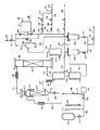
図1〜3は、それぞれ並列に連結された2つの水素化反応器内で、ジメチル1,4−シクロヘキサンジカルボキシレートの水素化により1,4−シクロヘキサンジメタノールを製造するための、プラントの簡略化されたフローチャートである。
図4は、単一水素化ゾーン内でジメチル1,4−シクロヘキサンジカルボキシレートの水素化により1,4−シクロヘキサンジメタノールを製造するための実験的装置の、簡略化されたフローチャートである。
【0050】
図はフローチャートであり、商業的プラントでは更に温度および圧力センサー、圧力リリーフバルブ、コントロールバルブ、レベルコントローラーなどの装置部材が付加的に必要となることは、当業者にとって更に理解出来るところであろう。このような付属の装置部材を設けることは、本発明の必須構成要素ではなく、慣用的な化学工学技術に過ぎない。更に、本発明の範囲は、様々な流れの加熱、気相化および凝縮の具体的な方法、またはそのために設けられる加熱器、熱交換器または気相化あるいは凝縮装置の配列により、何ら制限を受けるべきものではない。本発明の要件を満たす図に示された以外の装置を、慣用的な化学工学技術に従い、図示されている装置の代わりに用いることも出来る。
【0051】
図1を参照するに、テクニカル級ジメチル1,4−シクロヘキサンジカルボキシレートは、操作の第1相において、ライン1でパッキング4の床上の蒸発器容器3の上部に位置する蒸発器ノズル2に供給される。熱水素含有気体流は、ライン5で蒸発器容器3の底部に供給される。ジメチル1,4−シクロヘキサンジカルボキシレートを含む飽和気相状混合物は、ライン6で蒸発器容器3の頂部から回収される。生じた気相状混合物を、更にバルブ8で調節しながらライン7からの熱水素含有気体と混合する。ガス:ジメチル1,4−シクロヘキサンジカルボキシレートのモル比400:1を有し、圧力約900psia(約63バール)、温度約230℃である混合流をバルブ9およびライン10により、還元銅クロマイト触媒またはDRD92/89と呼称されるクロムを含まない触媒のようなペレット化した不均一系水素化触媒12の床を含む水素化反応器11に送り込む。水素化反応成績体混合物は、ライン13を経て反応器11から出て行き、バルブ14を通ってライン15に入る。ライン15へ入った水素化反応成績体混合物は、熱互交換器16で冷却され、生じた部分的凝縮混合物は、ライン17で冷却器18を通り、そこで更に冷却される。生じた気体と凝縮物の混合物はライン19で気体−液体分離器20へ流れて行き、そこからメタノールと粗1,4−シクロヘキサンジメタノールの混合物がライン21で回収される。ライン22における未凝縮の気体状混合物は、不活性気体およびメタノール気相と共に未反応水素を含んでおり、コンプレッサー23により圧縮されて、ライン24で圧縮気体流を得る。
【0052】
ライン24における圧縮再循環気体をライン25からの供給水素含有気体と合する。ライン26におけるこの合した混合物を、熱交換器16を通過させて加熱し、ライン27で加熱器28に流し込み、その温度をジメチル1,4−シクロヘキサンジカルボキシレート供給物の気相化をもたらすに適当な温度まで上げる。生じた熱気体をライン29で2つの気体流に分け、一方はライン5の、他方はライン30の気体流とする。この後者の気体流を更に加熱器31で約240℃まで加熱し、ライン32、バルブ33およびライン34と35を通過させて、操作の第1相では再活性化モードとなっている第2の水素化反応器36の底へ導く。反応器36は水素化触媒37の充填物を含有している。ライン7で反応器36の頂部を出た熱気体を、既に記載したようにライン6での飽和気相状混合物と混合し、その中の水素:ジメチル1,4−シクロヘキサンジカルボキシレートのモル比を増大させ、その温度を露点以上、例えば少なくとも5〜10℃以上高い温度に上げる。
【0053】
プラントはまたライン38および39とバルブ40および41を含んでおり、両方ともこの操作相では閉じられている。ライン42は、蒸発器容器3の底部に集められた“重質類(heavies)”を含有する流れを吸引し得るものである。43は、循環気体中に不活性ガスが増えるのを制限するため、パージガス流を取り出すことが出来るパージガスラインを示している。このような不活性ガスはライン25で供給気体流にまぎれてプラントに入ることがある。
【0054】
操作期間後、触媒充填物12の活性は再活性化が望まれる点まで低下しているであろう。触媒不活性化の理由は明確ではないが、この触媒活性の損失の原因として考えられるのは、エステル交換反応により触媒表面上に不揮発性ポリエステルの痕跡が形成されることである。このエステル交換反応は、例えばジメチル1,4−シクロヘキサンジカルボキシレートと、1,4−シクロヘキサンジメタノールまたは水素化反応の中間生成物であると考えられるメチル4−ヒドロキシメチルシクロヘキサンカルボキシレートもしくはジメチル1,4−シクロヘキサンジカルボキシレートと1,4−シクロヘキサンジメタノールエステルとの間の交換生成物であるヒドロキシメチルシクロヘキシルメチル1,4−シクロヘキサンジカルボキシレートとの間で生ずるものと推定される。生成した2量体または3量体物質は、更に気相状混合物の成分と反応して、これらの低重合体鎖を伸長させることとなる。ポリエステルおよび混合ポリエーテル−ポリエステルもまた形成することがある。
【0055】
このような触媒表面上の重合体副生物は、水素化されやすい。故に、熱水素含有気体との処理による触媒の再活性化が可能である。更に本発明の背景をなすジメチル1,4−シクロヘキサンジカルボキシレートの水素化に関する実験研究過程において、理由はともあれ、部分的に不活性化された触媒の熱水素含有気体流による処理は、触媒活性を少なくとも部分的に回復させるに有益な効果を示すことが認められた。
【0056】
従って、操作の第2相では、バルブ33を閉じ、バルブ41を開けると共に、バルブ14を閉じ、バルブ40を開ける。これにより、新しいまたは再活性化した触媒充填物37を持つ水素化反応器36を稼働させ、他方、反応器11を再活性化モードにし、その触媒の部分的不活性化充填物12を再活性化する。この操作の第2のモードでは、ライン6の飽和気相状混合物をライン10からの熱水素含有気体と混合して気相状供給混合物を形成させ、この混合物はライン7で反応器36とその触媒充填物37に流れる。生じた反応混合物は、ライン35および38によりバルブ40を通ってライン15に流れる。ライン32からの熱水素含有気体はバルブ41を通ってライン39に行き、その後ライン13を通って水素化反応器11の底部に行く。
【0057】
触媒充填物37がある程度不活性化したとき、バルブ14、33、40および41を再調整して水素化反応器11および36の流れを切り変えて操作の第1相の流れに戻すことが出来る。
【0058】
上記段階は、都合の良い程度に繰り返すことが出来、反応器11および36を再活性化手段によりもはや触媒活性が所望の増加を示さなくなるまで、またはプラントを整備またはその他の理由などで閉鎖しなければならなくなるまで順に稼働させ、そのうえで触媒充填物12および37を排出し、触媒または触媒前駆体の新しい充填物に置換することが出来る。
【0059】
ライン25における組み合わせ気体は、水素、COやCO2のような任意の少量成分およびアルゴン、窒素またはメタンのような不活性ガスの混合物であって、少なくとも水素を約70モル%含有するものであり得る。組み合わせ気体は、水素を好ましくは少なくとも90モル%、より好ましくは少なくとも97モル%含有する。組み合わせ気体は、常套の方法、例えば天然ガスの部分的酸化または気相改質、それに続く水性ガス移動反応およびCO2吸収、必要ならばそれに続く酸化炭素の残留痕跡の少なくとも幾分かのメタン化により製造することが出来る。高純度水素組み合わせ気体が所望ならば、圧力旋回吸収を用いることも出来る。
【0060】
プラントの運転開始時に、反応器11および36をそれぞれ、銅クロマイト触媒前駆体のような不均一系水素化触媒前駆体の充填物で充填する。しかしながら、反応器11および36は、DRD92/89のようなクロムを含まない水素化触媒を充填するのが好ましい。その後、触媒供給業者の指示に従って、触媒前駆体を注意深く還元する。EP−A−0301853の方法を用いて銅クロマイト前駆体を還元する場合には、その後、触媒床12および37の両者を同時に還元することが出来る。触媒前駆体を予備還元した後、熱水素含有気体をプラント中に循環させる。蒸発器容器3および反応器11の入り口温度が適温に達したら、ライン1でのジメチル1,4−シクロヘキサンジカルボキシレートの流入を開始し、プラントを操作の第1相で稼働状態にする。
【0061】
図2は、図1と同じ符号を用いており、同じ装置部材を示している。図1のプラントの場合、水素含有気体は、再活性化モードの間、触媒床12または37を気相状供給流が稼働モードで流れる方向とは逆方向に流れるのに対し、図2のプラントの場合、気体が触媒床12または37を流れる方向は、触媒床活性化モードでも稼働でも同じである。
【0062】
図2のプラントにおいて、ライン32における気体流からの熱気体は、バルブ51およびライン52を経てライン7、その後反応器36へと供給されるか、バルブ53およびライン54を経てライン10、その後反応器11へと供給されるかのいずれかであり得る。もし、反応器11が稼働モードでバルブ8が閉じており、反応器36が再活性化モードであるならば、バルブ51を調整して、ライン32からの気体の殆どをバルブ51を通して反応器36へ流し、反応器11の入り口温度を露点以上に上げるに充分な気体のみをバルブ53を通してライン10へ流す。反応器36を稼働モードにするため、バルブ9を閉じ、バルブ8を開ける。その上でバルブ51を幾分か閉じ、それに対応する程度にバルブ53を開け、ライン32からの気体のほとんどを反応器11に流す一方、露点必要条件を満たすに充分な気体のみをバルブ51に通す。
【0063】
図2のプラントにおいて、反応モードで放出される揮発性潜在的触媒不活性化物質は、稼働状態の触媒充填物を通過せず、ライン21で成績体流中に回収され得る。水素化されつつある不飽和有機化合物がジメチル1,4−シクロヘキサンジカルボキシレートである場合、このような触媒不活性化物質は何ら放出されないと言う予めの指摘もあるが、他の不飽和有機化合物が水素化されつつある場合は必ずしもそうではない。
【0064】
図3は、本発明にかかる水素化プラントの更に他の態様を説明するものである。このプラントにおいては、図2のプラントの場合と同じく、気体がそれぞれの再活性化モードの間、各触媒床12および37を通過して流れる方向は、気相状供給混合物が稼働モードの間に流れる方向と同じである。図3で使用した符号は、図1そのてまた図2で見られた装置部材と同じものを指している。
【0065】
図3のプラントにおいて、ライン1で入って来るジメチル1,4−シクロヘキサンジカルボキシレートの気相化のためにライン5で供給される水素含有気体は、まず、触媒床12または37の1つをその再活性化モードで通過する。従って、反応器36が再活性化モードである場合、ライン29の熱気体の殆どがバルブ51およびライン52を通り、触媒充填物37を通って反応器36に供給され、ライン35およびバルブ61を通って流れ、ライン5に入る。バルブ8および40を閉じ、露点必要条件を満足させるに充分な気体がライン10に入る限度においてバルブ53を開ける。一方、ライン6の気相供給混合物はバルブ9を通り、ライン10を経て、その触媒充填物12が稼働モードである反応器11に入る。ライン13の成績体流は、バルブ14を通ってライン15に流れ込み、バルブ62は閉じている。触媒充填物37を稼働状態とし、反応器11の触媒充填物12を再活性化するのが望ましい場合、バルブ8、40および62を開ける一方、先に開けていたバルブ9、14および61を閉める。バルブ53を幾分か開け、バルブ51を通って流れる気体量を露点を考慮して必要な程度で減少させる。触媒充填物37が再活性化し、触媒充填物12が再び稼働している先の条件に戻すために、種々のバルブの条件をそれぞれ前の条件に調整し直す。この方法を、反応工程がもはや触媒活性の増大が所望の結果とならなくなるまで、またはプラントが整備または他の理由で停止しなければならなくなるまで反応器11および36を次々に稼働状態にし、すぐに触媒充填物12および37を放出し、新しい触媒充填物または触媒前駆体と交換できるのが好都合なように、1度またはそれ以上繰り返してもよい。
【0066】
当分野の技術者は、ジメチル1,4−シクロヘキサンジカルボキシレートが本発明の方法を例示するのに適当な材料として選択したのであり、本発明の方法はジメチル1,4−シクロヘキサンジカルボキシレートを含む水素化反応の適用に限定するものではなく、実際、不揮発の水素化副産物が形成され触媒表面に付着する、エステル、ジエルテルまたはラクトンを供給保存物を使用した多くの気相層水素化反応、例えばジメチルまたはジエチルマレートのブタン−1,4−ジオールを産生するための水素化に適用し得る。
【0067】
以下に実施例を挙げて、本発明を更に詳細に説明する。実施例で使用された銅含有触媒AおよびBの組成は、表Iに示したとおりである。触媒の酸素含量は、各場合において分析対象から除外された。
【表1】

【実施例】
実施例1〜7
テクニカルグレイドのジメチル1,4-シクロヘキサンジカルボキシレートの水素化について、図4に示した実験装置を用いて調べた。
テクニカルグレードの供給物の組成は、以下の通りである:トランス-ジメチル1,4-シクロヘキサンジカルボキシレート34.47重量%、シス-ジメチル1,4-シクロヘキサンジカルボキシレート62.61重量%、以下の式:
【化1】
【化2】
【0069】
商業的プラントでは、水素ガスを、水素化生成物から分離して有利には水素化ゾーンへリサイクルさせている。水素リサイクル流は所定量の、ジメチル1,4-シクロヘキサンジカルボキシレートの水添によって生成したメタノール気相を含んでいる。よって、商業プラントの水素化ゾーンに供給された気相混合物は、一般に水素および不飽和有機化合物に加え、メタノールを含んでいる。以下に記載の実験装置は、商業的操作で得られるであろう結果を正確に予測できるものでなければならず、このため、蒸発器へ供給される液体供給物につき、商業プラントのリサイクル水素流に含まれるであろう所定量のメタノールに相当する所定量の液体メタノールによって修正した。以下に記載の実験装置では水素をリサイクルさせるが、リサイクル水素流中に含まれる所定量のメタノールは、対応する商業的リサイクル流に含まれるものよりも比較的少ない量とした。この差異が生じたのは、実験装置内のリサイクルガスが、商業プラントで好適に冷却される温度よりも実質的に低い温度に冷却されるためである。このため、実験上のリサイクル水素流から、より多量のメタノールが「たたき出される」 。実験装置と商業プラントの間のこの不一致は、実験装置に用いられる器具、とくに分析器具の精巧さにより必然的なものである。これらの実施例において、メタノールを実験用の液体生成物に対し、実験用リサイクル水素流中に実際に存在するメタノール量を差し引いた、仮に実験装置を商業的な条件下に操作した場合に実験用リサイクル流中に存在する釣りあったメタノール量と実質的に等しい用量で添加する。当該実施例では、転化率や単位時間当たりの空間速度のような全てのパラメーターは、メタノール不存在下の基準で算出した。
【0070】
実験用装置は図4に示した。約70重量%メタノール溶液の高純度グレイドのジメチル1,4-シクロヘキサンジカルボキシレートを貯蔵器100からバルブ101、ライン102およびバルブ103により液体供給ポンプ104へ供給する。ビュレット105は緩衝的な供給を付与する一方、ビュレット106はバルブ101をコントロールする液体レベルコントロラー(図示せず)を付設して備え、その結果、液体供給物の、貯蔵器100から液体供給ポンプ104への一定の水頭での供給が保証される。液体供給物を非返還バルブ107および単離バルブ108を介してライン109へポンプ供給するが、ここは、加熱液体が6mm×6mmのガラスリング112床上方の絶縁蒸発器111内に入る前に電気加熱テープ110で加熱することができる。ステンレススチール・デミスターパッド113は蒸発器111の頂部に付設する。高温水素含有ガスの流はライン114の蒸発器111の底部に供給する。ドレインバルブ116を付設して備える液体ドレインライン115は蒸発器111の基部から未蒸発液体供給物質(たとえば、重質類)の回収を可能にさせる。蒸発器111へ供給された液体供給物の蒸発は、加熱テープ117により促進される。ジメチル1,4-シクロヘキサンジカルボキシレートおよび水素からなる飽和蒸発混合物は、蒸発器111の頂部からライン118により回収する。気相混合物は、粒状亜クロム酸銅水素化触媒121(300ml、428.1g)床を含む水素化反応器120の頂部に入る前に、加熱テープ119により加熱して当該混合物の露点以上の温度に上昇させる。当該触媒は表Iの触媒Aである。ガラスリングは反応器120内の触媒床121の上下に充填する。気相混合物は、ジメチル1,4-シクロヘキサンジカルボキシレートの1,4-シクロヘキサンジメタノールへの転化が断熱条件で生じる触媒床121を介し下方に進行する。断熱性は、反応器120周囲の絶縁物質内の電気加熱テープ(図示せず)により、好適な位置に配置した熱電対(図示せず)のコントロールの下に維持される。総反応は穏やかな発熱反応で、触媒床の温度は通常約1〜2℃上昇する。水素化生成混合物は、ライン122の水添反応器120に存在し、熱交換器123を通過するが、この熱交換器は、水素化生成混合物の冷却と、ライン124からの水素含有ガスの供給物の加熱を同時に行う。ライン122における1,4-シクロヘキサンジメタノールの大半の凝縮は熱交換器123で起こる。ライン124のガスはライン125からの水素含有ガスからなり、所望によりライン126から供給されたメタン、アルゴン、窒素などの不活性ガスの混合物または単独の不活性ガスを含む。ライン125のガスはライン127により供給された補給水素と、ライン128により供給されたリサイクル水素から構成される。ライン127による補給水素は、ライン129および/またはライン130の流れにより、ライン125へ、圧力コントロラー131〜136および高純度水素シリンダー(図示せず)からのマスフロー・コントロラー137のシステムを介して供給する。
【0071】
熱交換器123からの加熱水素含有ガスは、ライン114を通過し、さらに電気的加熱テープ138により加熱し、蒸発器111へ供給する。
熱交換器123からの冷却水素化生成物はライン139を通過し、さらにクーラー140で室温付近の温度に冷却する。クーラー140からの液体/気相混合物はライン141を通過して、第1ノックアウト・ポット142に入るが、ここに液体水素化生成物が集められ、バルブ143、ライン144およびコントロールバルブ145による最終的な供給によって製品ライン146へ送られる。水素および未凝縮メタノールからなる気相混合物は、ライン147のノックアウト・ポット142の頂部に存在し、さらにクーラー148で温度10℃に冷却される。クーラー148からの付加的に冷却した液体/気相混合物は、ライン149を介し、第2ノックアウト・ポット150へ供給するが、ここに凝縮メタノールが集められ、バルブ151およびライン152を介する最終的な供給により製品ライン146へ送る。ノックアウト・ポット150からのガスおよび未凝縮物質は、ライン153を介し吸引ポット154を通ってライン155内に入り、次いでバルブ156を介してガスリサイクル圧縮器157へ送る。ガスは、バルブ158、ライン128、125、124および114を介して貯蔵器111へリサイクルする。窒素などの不活性ガス濃度のコントロールのために、リサイクルガス中に、パージガス流をライン159のシステムからバルブ160のコントロールの下に流入させる。
【0072】
参照番号161バイパスバルブを示す。
本発明の装置の始動時点で、銅含有触媒充填物を反応器120へ内に入れ、次いで窒素で当該反応器をパージする。触媒充填物を次いでEP-A-0301853開示に従い還元した。
メタノールで好適に希釈したテクニカルグレードのジメチル1,4−シクロヘキサンジカルボキシレートを次いで蒸発器111へ、適当な単位時間当たりの液体空間速度に対応する供給速度でポンプ輸送する。ライン118における気相混合物中の供給温度、供給圧およびガス:ジメチル1,4-シクロヘキサンジカルボキシレートのモル比は、水素化ゾーンがジメチル1,4-シクロヘキサンジカルボキシレートおよび揮発性が低い1,4-シクロヘキサンジメタノール生成物の両方についての凝縮を防止可能な条件下で操作することができるように選択する。水素化ゾーン全体の温度は操作圧力における露点以上であった。
【0073】
ライン146の液体は、毛管ガスクロマトグラフィにより、長さ15mおよび内径0.32mmの溶融シリカカラム(DBワックスの0.25μm膜で内部被覆)、ヘリウム流速2ml/分(ガス供給分割比= 100:1)およびフレーム・イオン化検出器を用い、定期的に分析した。当該機器はピーク・インテグレイターを有するチャート・レコーダーを備え、市販の試料である既知組成のジメチル1,4-シクロヘキサンジカルボキシレートを用いて検定した。また出口ガスを採取し、ガスクロマトグラフィによりクロマトグラフィ法を用いて分析した。ピークの同定は、当該物質の基準試料の分析によって観察された保持時間の比較およびマススペクトルにより確認した。反応混合物中に検出された化合物には、以下のものが含まれていた:1,4-シクロヘキサンジメタノール、ジメチル1,4-シクロヘキサンジカルボキシレート、4-メトキシメチル・シクロヘキサンメタノール、ジ(4-メトキシメチルシクロヘキシルメチル)エーテルおよびメタノール。装置の稼働は、数週間の期間にわたって追跡した。得られた結果から、この期間の間に、ジメチル1,4-シクロヘキサンジカルボキシレートは、99%以上転化され、1,4-シクロヘキサンジメタノールへの選択率約98.5%が得られ、少量の副産物が残部であると思われる。貯蔵庫100からのジメチル1,4-シクロヘキサンジカルボキシレートの供給溶液中に存在するメタノールを差し引くと、水添反応の化学量論に従い転化されたジメチル1,4-シクロヘキサンジカルボキシレート1モルごとに、メタノール2モルが検出された。
【0074】
装置の更なる稼働の後、下記の表IIに記載の実施例1で特定した条件下では、ジメチル1,4−シクロヘキサンジカルボキシレートへの転化は97.53%であり、1,4−シクロヘキサンジメタノールへの選択性は96.89%であった。稼働条件を次に表IIに記載の実施例2の条件に変えた。装置の稼働は、数日間続け、その間中、ジメチル1,4−シクロヘキサンジカルボキシレートの所望の転化を維持するために、供給温度を3℃上昇させることが必要であった。観察された結果は実施例3、表IIに説明する。装置を、所望の用量に近いジメチル1,4−シクロヘキサンジカルボキシレートの転化を維持するために、実施例2と比較して供給温度が6℃だけ上昇させることにより明白なように、数週間にわたって活性が減少する、更なる期間稼働し続けた。この期間の結果は実施例4に示す。稼働はさらに数日続けた。ついで条件を、実施例5の表IIに示してあるように変え、それは実施例1に特定されている条件と同等である。実施例1と比較して、転化は稼働がその間に97.53%から85.47%に減少し、したがって触媒活性の非常に顕著な減少が起こった証明となる。
【0075】
ジメチル1,4−シクロヘキサンジカルボキシレート供給を次にやめ、約3時間の間隔の後、反応容器120の供給温度を250℃に上昇し、水素ガスを反応器120にこの温度で14時間通し、触媒を再活性化した。反応器120は次に、再活性化工程直前と同じ条件に戻した。ジメチル1,4−シクロヘキサンジカルボキシレート転化は触媒再活性化直後、実施例6に記載してあるように約91.86%であり、少なくとも部分再活性化は十分行われた。これは実施例4と実質的に同様な稼働条件で再現して確認された。転化は、供給温度236℃で、実施例4に記載の98.61%から実施例7に記載の99.79%に上昇した。
【0076】
実施例1、5および6の比較は、実施例1から5の間に触媒が活性をジメチル1,4−シクロヘキサンジカルボキシレートの転化で測定して、実施例1の任意の相対活性100%から、基本を同じにして測定した実施例5の相対触媒活性87.63%に減少したことを示す。再活性化工程の後、触媒活性は、実施例6の記載し多様に、元の値の94.19%に再蓄積された。
【0077】
【表2】
DMCD= ジメチル1,4−シクロヘキサンジカルボキシレート
LHSV= 単位時間当たりの液体空間速度
CHDM= シクロヘキサンジメタノール
BYPR= 種々の副生物
METH= 4−メトキシメチル・シクロヘキサンメタノール
DETH= ジ−4−ヒドロキシメチルシクロヘキシルメチル・エーテル
ガス= 水素98%以上を含む、水素含有ガス
【0078】
実施例8〜12
実施例1〜7に記載と同様な方法および同じ方法を用い、いずれもブタン−1,4−ジオールを産生するジメチルマレート、ジエチルマレート、ジメチルフマレートまたはガンマ−ブチロラクトンをジメチル1,4−シクロヘキサンジカルボキシレートの変わりに用いて行う。同様の触媒活性の改善が再活性化法の後観察される。
【0079】
実施例13
触媒Aを触媒Bに変えたこと以外、実施例1〜7に記載と同様な方法を行い、同様なよい結果である。
【0080】
実施例14
本方法で使用するのに設計した実験装置は、図1に示した型のプラントで操作するようにする。この装置は、反応器120が一連の一対の反応器に変わっている以外本質的には図4に示すものと同一である。第1の反応器を稼働し、それに供給される気相供給混合物を水素化するに有効な条件下で維持し、第2の反応器は待機または再活性化モードでそれに供給される水素化材料は存在しないで、実施例1〜7に記載の一般的方法を繰り返した。第1の反応器内の触媒充填物の段階的な不活性化は、事実上実施例1〜7に記載してあるように観察される。第1の反応器内の触媒充填物を再活性化するために、それに供給される気相供給混合物を第2の反応器に変え、それにより、水素化反応を第2の装置内で続けさせた。一方、第1の反応器に水素含有ガスを供給し、それによりその中の触媒充填物の再活性化を行う。第2の容器内の触媒活性が実施例1〜7に記載の1個の水素化反応器内のと同様に減少した後、気相供給物混合物を第1の反応器に戻し、それにより水素化反応を続けさせ、一方再活性工程を第2の反応器で行う。第1の反応器での水素化触媒の活性は1個の水素化ゾーンで記載したのと同様に顕著に上昇するのが観察された。全ての工程を数回繰り返し、ジメチル1,4−シクロヘキセンジカルボキシレートの転化は優秀であるままである。
【図面の簡単な説明】
【図1】 本発明方法の一実施態様を示すフローチャートである。
【図2】 本発明方法の他の一実施態様を示すフローチャートである。
【図3】 本発明方法の他の一実施態様を示すフローチャートである。
【図4】 本発明方法の試験的規模における一実施態様を示すフローチャートである。
【符号の説明】
2 蒸発器ノズル
3 蒸発器容器
4 パッキングベッド
11、36 反応器
12、37 水素化触媒床
16 熱交換器
18 冷却器
20 気液分離器
23 コンプレッサー
28、31 加熱器[0001]
[Industrial application fields]
The present invention relates to a gas phase hydrogenation process.
[0002]
[Prior art]
Various processes have been disclosed for the production of alcohols and diols by hydrogenation of the corresponding unsaturated organic compounds selected from esters, diesters and lactones in the presence of a heterogeneous ester hydrogenation catalyst. Such unsaturated organic compounds are unsaturated because they have a carbon-oxygen double bond in the-(CO) -O- bond. These compounds do not need to have further unsaturated bonds. That is, this type of hydrogenation process involves various esters, diesters and lactones that do not contain unsaturated bonds in addition to the carbon-oxygen double bonds described above, such as C 8 ~ C twenty two Monoester of alkyl carboxylic acid, C Four ~ C 16 It can be applied to diesters of dicarboxylic acids and lactones of hydroxycarboxylic acids containing 4 to 16 carbon atoms. However, it does not extend to unsaturated bonds further present in the molecule. That is, such methods can be used for esters, diesters and lactones that contain further unsaturated bonds in the molecule, 8 ~ C twenty two It can be used for monoesters of aliphatic carboxylic acids, diesters of unsaturated aliphatic or alicyclic carboxylic acids and unsaturated lactones.
[0003]
Many examples of such hydrogenation processes are conventionally carried out in the liquid phase, hydrogenation of aliphatic monocarboxylic acids from alkyl esters to alkanols, and hydrogenation of aliphatic dicarboxylic acid dialkyl esters to aliphatic diols. including. In some cases it has been proposed to carry out the hydrogenation reaction under gas phase reaction conditions.
[0004]
The production of cycloaliphatic diols, cyclohexanedimethanol by hydrogenation of the corresponding cycloaliphatic diesters, usually the corresponding dialkyl benzenedicarboxylates, such as dialkylcyclohexanedicarboxylate, which can be produced by hydrogenation of dimethyl terephthalate. It is known.
[0005]
Commercially available hydrogenation catalysts used for carboxylic acid ester hydrogenation catalysts are copper chromite, optionally promoted by barium and / or manganese. The use of this catalyst in the preparation of butane-1,4-diol is disclosed in EP-A-0143634. WO-A-82 / 03854 discloses a process for hydrocracking a carboxylic acid utilizing a catalyst containing a reduced mixture of copper oxide and zinc oxide. Other catalysts that may be used for the hydrogenation reaction that may be mentioned are the palladium / zinc containing catalysts of WO-A-89 / 00886 and the mixed catalyst system of EP-A-0241760. Manganese promoted copper catalysts are also commercially available as hydrogenation catalysts.
[0006]
The hydrogenation reactor is operated adiabatically or isothermally by external or internal cooling. An adiabatic reactor is used when it is superior because it is easier to construct and operate than a thermostat reactor of shell type or tubular type.
[0007]
Hydrogenation of ester, diester and lactone feeds is generally an exothermic reaction. In a liquid phase reaction, the feed is usually diluted with an inert diluent, conveniently a recycled product hydroxy compound, and the catalyst is totally wetted with liquid. Dilution acts as a heat drop and serves to prevent the risk of damaging the catalyst due to the exothermic nature of the hydrogenation reaction.
[0008]
In typical gas phase hydrogenation processes, unsaturated organic compounds, ie esters, diesters or lactones, are usually vaporized directly into a heated hydrogen-containing gas, resulting in a gas phase mixture that is further heated, Further dilution with heated hydrogen-containing gas to raise the temperature above the dew point. It is important to ensure that the gas phase mixture normally in contact with the catalyst is above its dew point, i.e. above the temperature at which the gas mixture and vapor condense as a mist or film. This condensed liquid normally dissolves all condensed compositions and gases in the gas phase at a concentration that satisfies the normal gas phase / liquid phase critical point. It may contain starting materials, intermediate products, by-products and / or final hydrogenation products. Generally, this process is operated at a temperature of the steam feed mixture above its dew point, such as about 5 ° C. to about 10 ° C. above the dew point. Furthermore, it is desirable to prevent contact of the catalyst with liquid dew drops, especially dew drops rich in unsaturated organic compounds. Because catalyst degradation can lead to sintering due to reduced physical strength, the formation of hot spots on the catalyst surface or in the catalyst pores, and the exothermic nature of the reaction. This is because the catalytically effective catalyst surface (especially in the case of copper-containing catalysts) can be attributed to catalyst pellet collapse as a result of the possibility of explosive vapor in the pellet holes. The conditions of the hydrogenation reactor to prevent the maturation of the hydrogenation catalyst by a mechanism such as the formation of a heat spot on the catalyst surface is disclosed in WO-A-91 / 01961.
[0009]
Even with sufficient care to maximize the life of the hydrogenation catalyst, it is still possible to ensure that the hydrogenation catalyst is generally significantly deactivated, for example as described in WO-A-91 / 01961. It is recognized in the art that exposure to conditions in the hydrogenation range in which catalytic activity can be irreversibly reduced. Such inactivation may be due to various reasons in different hydrogenation reactions. For example, the deposition of carbon or carbonaceous material on the catalyst surface causes a decrease in catalyst activity. In addition to this deactivation process, the catalyst pellets physically disintegrate and powder over time, blocking the vapor passage through the catalyst bed, and an unacceptable increase in pressure drop through the catalyst bed. Tend to lead. The inactivation process may be gradual but not easily reversible.
[0010]
In commercial hydrogenation processes, the catalyst eventually loses activity and / or selectivity and needs to be replaced with a new catalyst charge. There are many unrelated but complementary reasons for catalyst deactivation in hydrogenation reactions. These include i) deposition of carbonaceous material on the catalyst surface, ii) pulverization or structural degradation of catalyst pellets resulting from local physical conditions, iii) catalyst poisons, especially those containing chlorine or sulfur, and iv) Sintering of the catalyst when the catalyst is a copper-containing catalyst and at a high temperature, for example, well above 230 ° C.
[0011]
In a hydrogenation reaction using a copper-containing catalyst, the catalyst is easily deactivated due to sintering (considered) and due to metal migration, and the catalyst particles collapse into a fine powder and become physically It is generally accepted in the art to lead to a reduction in physical strength. That is, the catalyst deactivation of the copper-containing hydrogenation catalyst is considered irreversible. Thus, for example, as suggested by US-A-3334149, attempts to reactivate copper-containing catalysts deactivated as a result of long-term use in liquid phase hydrogenation of dimethyl 1,4-cyclohexanedicarboxylate were unsuccessful. .
[0012]
Hydrogenation processes that allow reversible or slowdown of the deactivation process are believed to have significant commercial advantages over known processes in the art due to lower catalyst consumption costs. Such a process also has significant environmental advantages resulting in a reduction in catalyst turnover.
[0013]
Summary of invention
The object of the present invention is therefore to provide a method for reactivation of an ester hydrogenation catalyst after the catalytic activity in use has been reduced in the hydrogenation of esters, diesters and lactones. A further object of the present invention is C 8 ~ C twenty two A process for hydrogenating unsaturated organic compounds selected from monocarboxylic acids, dicarboxylic acid diesters and lactones to produce the corresponding alcohols or diols, wherein the lifetime of the copper-containing catalyst used therein is cyclically reactivated. It is a method characterized by prolonging the life.
[0014]
[Means for solving the problems]
The present invention is a process for producing a hydroxy compound selected from alcohols and diols by hydrogenation of a corresponding unsaturated organic compound selected from esters, diesters and lactones,
(a) providing at least two hydrogenation zones each comprising a charge of effective particulate hydrogenation catalyst to catalyze the hydrogenation of unsaturated compounds to hydroxy compounds;
(b) supplying at least one hydrogenation zone with a gas phase feed stream comprising a hydrogen-containing gas and an unsaturated organic compound in the first step of operation;
(c) maintaining at least one hydrogenation zone at temperature and pressure conditions that hydrogenate unsaturated organic compounds to form hydroxy compounds in the first step of operation;
(d) recovering a reaction product stream comprising a hydroxy compound from at least one hydrogenation zone in a first step of operation;
(e) supplying at least one other hydrogenation zone with a hydrogen-containing gas stream that reactivates the charge of the hydrogenation catalyst contained therein in the first step of operation;
(f) supplying at least one other hydrogenation zone with a gas phase feed stream comprising a hydrogen-containing gas and an unsaturated organic compound in the second step of operation;
(g) maintaining at least one other hydrogenation zone at temperature and pressure conditions to hydrogenate unsaturated organic compounds to form hydroxy compounds in the second step of operation;
(h) recovering a reaction product stream comprising a hydroxy compound from at least one other hydrogenation zone in a second step of operation; and
(i) supplying at least one hydrogenation zone with a hydrogen-containing gas stream for reactivating the charge of the hydrogenation catalyst contained therein in the second step of the operation.
A method comprising:
[0015]
The process of the present invention is suitable for any ester, diester and lactone hydrogen that can be gasified with a significant vapor pressure at the feed temperature in each hydrogenation zone, for example, about 0.01 psia (about 0.001 bar). This method can also be used to carry out the conversion, and this method does not deposit the chemical element carbon on the catalyst. As will be appreciated by those skilled in the art, the present invention is not based on the discovery of any new hydrogenation reaction, or any new hydrogenation conditions, or any new catalyst, but instead the mechanical properties of the hydrogenation plant. It relates to arrangement and control and the overall flow of material through two or more hydrogenation zones present in the plant.
[0016]
Specifically, esters, diesters and lactones contain 30 or more carbon atoms. The unsaturated organic compound is preferably, for example, C 8 ~ C twenty two Monoester of alkyl carboxylic acid, C Four ~ C 16 Diesters of dicarboxylic acids, and lactones of hydroxycarboxylic acids containing 4 to 16 carbon atoms, and C 8 ~ C twenty two Selected from monoesters of aliphatic carboxylic acids, diesters of unsaturated aliphatic or alicyclic carboxylic acids and unsaturated lactones.
[0017]
Examples of hydrogenation reactions involving the use of ester, diester or lactone feedstocks, to which the suggestion of the present invention may be applied, are described in WO-A-91 / 01961, EP-A-014634, WO-A -86/03189 and the methods disclosed in WO-A-86 / 07358.
[0018]
Unsaturated organic compounds are di- (C) dicarboxylic acids containing at least 4 carbon atoms. 1 ~ C Four Alkyl) esters may also be used. That is, in one preferred method, the unsaturated organic compound is, for example, C Four Dialkyl esters of dicarboxylic acids, for example, dialkyl maleates, and the corresponding hydrogenation products are butane-1,4-diol, gamma-butyrolactone or tetrahydrofuran or mixtures of one or more thereof. In such a process, the copper-containing catalyst is preferably a reduced copper chromite catalyst, a reduction promoted copper chromite catalyst, or a reduced manganese promoted copper catalyst. Dialkyl maleates are usually di- (C 1 ~ C Four ) Alkyl, preferably dimethyl maleate or diethyl maleate.
[0019]
A similar reaction is hydrogenation of gamma-butyrolactone to produce butane-1,4-diol, or epsilon-caprolactone to produce hexane-1,6-diol.
[0020]
The unsaturated organic compound is cyclohexanedicarboxylic acid di- (C 1 ~ C Four Alkyl), for example, dimethyl cyclohexanedicarboxylate, and the hydrogenation product is cyclohexanedimethanol. That is, in a particularly preferred method, the unsaturated organic compound is dimethyl 1,4-cyclohexanedicarboxylate and the hydrogenation product is 1,4-cyclohexanedimethanol. Other reactions to which the process of the present invention can be applied are 1,2- or 1,3-cyclohexanedicarboxylic acid di- (C 1 ~ C Four Alkyl), for example, hydrogenation of dimethyl 1,2- or 1,3-cyclohexanedicarboxylate to 1,2- or 1,3-cyclohexanedimethanol, respectively.
[0021]
Other types of unsaturated organic compounds that can be used as starting materials in the process of the present invention can include esters, such as C 8 ~ C twenty two C of monocarboxylic acid 1 ~ C Four It is an alkyl ester. Specific esters include C 8 ~ C twenty two Methyl or ethyl esters of alkyl carboxylic acids, such as methyl laurate, methyl oleate, methyl stearate, methyl linoleate and the like.
[0022]
The particulate catalyst used in the method of the present invention is not particularly limited as long as it has an action of catalyzing the hydrogenation or hydrocracking of an ester to a corresponding alcohol or mixture. It may be formed into a suitable shape, such as pellets, rings or saddles.
[0023]
Typical copper-containing ester hydrogenation catalysts include alumina-on-alumina catalyst, reduced copper oxide / zinc oxide catalyst (with promoter if necessary), reduced manganese promoted copper catalyst, reduced copper chromite Catalyst (with promoter if necessary). Suitable copper oxide / zinc oxide catalyst precursors include those containing a CuO / ZnO mixture with a Cu: Zn weight ratio of about 0.4: 1 to 2: 1. An example is a catalyst precursor called DRD 92/71. The promoted copper oxide / zinc oxide precursor comprises a CuO / ZnO mixture with a Cu: Zn weight ratio in the range of about 0.4: 1 to 2: 1 and about 0.1-15. Promoted by weight percent barium, manganese or a mixture of barium and manganese. Thus, in the promoted CuO / ZnO mixture, there is a Mn-promoted CuO / ZnO precursor available under the designation DRD 92/92. Suitable copper chromite catalyst precursors include those having a Cu: Cr weight ratio in the range of about 0.1: 1 to 4: 1, preferably about 0.5: 1 to 4: 1. This type of catalyst precursor is available under the designation DRD 89/21 or PG 85/1. Suitable accelerated copper chromite precursors include those having a Cu: Cr weight ratio in the range of about 0.1: 1 to 4: 1, preferably about 0.5: 1 to 4: 1, and about 0.1. The reaction is accelerated by 1 to 15% by weight of barium, manganese or a mixture of barium and manganese. Manganese-promoted copper catalyst precursors typically have a Cu: Mn weight ratio of about 2: 1 to 10: 1, usually with a Cu: Al weight ratio of about 2: 1 to 4: 1. It contains an alumina support. A specific example is the catalyst precursor DRD 92/89.
[0024]
All catalysts having the above generic designations DRD or PG are available from Debbie Research and Development Limited, UK, Crivland TS18-3HA, Stockton-on-Tees, Bosfield Lane, PO Box 37 I can do it.
[0025]
As the physical support of the catalyst used in the method of the present invention, it is possible to appropriately use what is known as a support. Such a support includes zinc oxide, alumina, silica, and alumina. -Substances such as silica, silicon carbide, zirconia, titania, carbon, zeolite, or suitable combinations thereof.
[0026]
Particularly preferred catalysts for use in the process of the present invention are the reduced forms of copper chromite, promoted copper chromite, and manganese promoted copper catalyst precursors described above.
[0027]
In steps (e) and (i) of the process of the present invention, each charge of the hydrogenation catalyst is treated with a hydrogen-containing gas stream to thereby reactivate the catalyst charge. Usually, it is preferable to raise the temperature to carry out these steps, and specifically, it is about 150 ° C. to about 340 ° C. or more. The feed temperature to each hydrogenation zone (s) in these steps is lower than the feed temperature to the hydrogenation zones of the gas phase feed streams of steps (b) and (f). For example, it may be about 10 ° C to about 50 ° C lower, substantially equal, or about 10 ° C to 50 ° C higher. The feed temperature to the hydrogenation zone during reactivation steps (e) and (i) is about 10 ° C. to less than the feed temperature to the gas phase hydrogenation zone used in steps (b) and (f). It may be about 30 ° C. lower or about 10 ° C. to about 30 ° C. higher.
[0028]
The hydrogen-containing gas stream used in steps (e) and (i) may comprise a recirculated gas heat stream. Conveniently, the hydrogen-containing gas stream in at least one of (e) and (i) comprises a recirculated and make-up gas heat stream.
[0029]
The supply pressure in steps (e) and (i) may be the same, lower or higher than the supply pressure used in steps (b) and (f). Preferably it is substantially the same as the feed pressure used in steps (b) and (f) w @.
[0030]
In one form of the process of the present invention, at least one of steps (e) and (i) is mixed with a gas phase hydrogen-containing stream of an unsaturated organic compound and the corresponding one of steps (b) and (f). A hydrogen-containing gas stream is recovered to form a gas phase feed stream for the process.
[0031]
In another embodiment, a hydrogen-containing gas stream that is mixed with the corresponding one-step reaction product stream of steps (d) and (h) is recovered from at least one step of steps (e) and (i).
[0032]
Furthermore, in another embodiment of the method of the present invention, it is used to gasify the unsaturated organic compound from at least one of steps (e) and (i) to produce a hydrogen-containing gas phase stream of the unsaturated organic compound. A hydrogen-containing gas stream is recovered.
[0033]
In at least one of steps (b) and (f), it is further possible to form a gas-phase feed stream by co-mixing a thermal recycle gas with a gas-phase hydrogen-containing stream of unsaturated organic compounds. It is advantageous.
[0034]
The direction of flow of the hydrogen-containing gas through at least one of the hydrogenation zones of the zones of steps (e) and (i), respectively, is that of the gas-phase feed stream through one zone of the corresponding steps (b) and (f). It may be the same as or opposite to the direction of flow. It will usually be advantageous to operate at conditions such that the gas phase hydrogen-containing stream containing the unsaturated organic compound is substantially saturated with the unsaturated organic compound.
Preferably the gas phase feed stream of step (b) and / or step (f) is at a temperature at least 5 ° C. above its dew point.
[0035]
The hydrogenation zone can include shell-and-tube reactors that can be operated at a constant temperature or near a constant temperature, with the catalyst in the tubular reaction vessel and the coolant in the shell reaction vessel, or vice versa. Usually, however, it is preferred to use an adiabatic reaction vessel because it is less expensive to assemble and attach than shell-and-tube reaction vessels. Such adiabatic reaction vessels may each contain only the hydrogenation catalyst charge, or may contain two or more catalyst beds, or may contain different hydrogenation catalyst beds. Optionally, an external or internal inter-bed heat exchanger may be provided to regulate the feed temperature from the inlet to one or more catalyst beds downstream to the respective adiabatic hydrogenation reaction vessel. Good.
[0036]
In the process of the present invention, two or more hydrogenation zones can be used in parallel, at least one of which operates at any time and the other is in the reactivation mode. If there are only two zones, one zone is active and the other zone is in reactivation mode. If the plant has 3 or more zones, typically one or more zones are in reactivation mode and one or more are operating. Alternatively, if the plant has three or more zones, at least one zone is in operation, at least one zone is in standby mode, and at least one zone is in reactivation mode. The number of zones in operation, reactivation or standby mode at a given time will depend on the desired plant operator and the economic issues associated with the particular hydrogenation reaction concerned.
[0037]
In general, gas phase hydrogenation processes that are very exothermic are those in which the unsaturated organic compound in the gas phase hydrogen-containing reaction mixture is above its dew point, and therefore in the gas phase form rather than in the liquid form, while simultaneously contacting the hydrogenation catalyst. It is important to ensure that In this method, the risk of water droplets in the liquid layer rich in unsaturated organic compounds containing the catalyst and the occurrence of local “hot spots” and the explosive locality of the liquid in the catalyst pores The risk of “fine dust” formation due to gasification is minimized. However, in some cases, especially when the evaporation of the hydrogenated product is significantly less than that of the unsaturated organic compound, the concentration of the catalyst on the hydrogenated product rich liquid layer can be noticeable. Thus, in some cases, for example in hydrogenation to produce 1,4-cyclohexanedimethanol of dimethyl 1,4-cyclohexanedicarboxylate in the catalyst gas phase, the reaction product mixture at the downstream end of the catalyst bed is hydrogenated. It is not always necessary to be above the dew point of the chemical product. Thus, gas phase conditions need to be above the dew point at the inlet end of the catalyst bed with unsaturated organic compounds, while mixed gas-liquid conditions are allowed at the catalyst bed end outlet. In the hydrogenation process, it is important that the product, for example 1,4-cyclohexanedimethanol, is considerably more volatile than the unsaturated organic compound such as the starting material 1,4-cyclohexanedicarboxylate. In such a process, the molar ratio of gas: unsaturated organic compound must be high enough to maintain the gas phase feed stream above the dew point, but the reaction product stream at the catalyst bed inlet end is above the dew point. It does not have to be so high as to maintain. Since the amount of circulating gas can be reduced, it has a significant effect on plant size and operating costs, so that less transportation work and smaller gas recirculation condensates than if the reaction product stream is also above the dew point. Enable the use of a presser.
[0038]
The hydrogen-containing gas: unsaturated organic compound molar ratio in the gas phase feed streams of steps (b) and (f) varies within a wide range depending on the temperature, pressure and volatility of the unsaturated organic compound. Can do. The main gaseous component is hydrogen, but other gases are also usually in low concentrations, and the process is combined with such things as nitrogen, argon, methane and carbon oxide in a hydrogen-containing gas as a make-up gas. Can be introduced. The lower the evaporation of the unsaturated organic compound, the less the evaporation at a given temperature and the higher the hydrogen-containing gas: unsaturated organic compound molar ratio in order to maintain the evaporation feed mixture above the dew point at the appropriate temperature. Conversely, if the organic compound evaporates more, the molar ratio needs to be low. Usually the range is from about 10: 1 to 8000: 0, preferably from about 200: 1 to about 1000: 1.
[0039]
The hydrogen-containing gas used in steps (b), (e), (f) and (i) of the present invention can include fresh combined gas or a mixture of combined gas and recycle gas. The combined gas is hydrogen and CO or CO 2 A mixture of any minor components such as, and an inert gas such as argon, nitrogen or methane, which may contain at least 70 mole percent hydrogen. The combined gas may preferably contain at least 90 mol%, more preferably at least 97 mol% hydrogen. The combined gas may be produced in any suitable manner, such as partial oxidation or gas phase reforming of natural gas followed by water gas transfer reaction and CO 2 It can be produced by absorption followed by at least some methanation of residual traces of carbon oxide, if desired. If high purity hydrogen combination gas is required, pressure swing absorption can be used. When utilizing gas recirculation, the recycle gas typically contains a small amount of one or more of the hydrogenation reaction products that have not been sufficiently condensed in the product recovery stage downstream of the hydrogenation zone. For example, in the case of hydrogenation of dimethylcyclohexanedicarboxylate using gas recycle, the gas recycle stream will contain methanol.
[0040]
The method of the present invention is operated using a gas phase feed stream, where the feed rate of the hydrogenatable material to the hydrogenation zone is expressed as space velocity and the space velocity is expressed as liquid hourly space velocity. Is convenient. Therefore, it is convenient to express the supply rate by the ratio of the liquid supply rate to the gasification zone of the unsaturated organic compound to the hydrogenation catalyst capacity. Thus, the equivalent liquid hourly space velocity through the hydrogenation catalyst of the hydrogenatable material is preferably about 0.05 to 4.0 h. -1 It is. In other words, the liquid hydrogenatable material is fed at a rate per unit volume of catalyst equal to about 0.05 to 4.0 unit volume of hydrogenatable material per hour (ie, catalyst m Three About 0.05-4.0m per Three h -1 ) To the gasification zone. More specifically, the liquid hourly space velocity is about 0.1 to 1.0 h. -1 It is. If the unsaturated organic compound is solid at ambient temperature, it must be heated to melting or dissolved in a suitable inert solvent, in which case the solvent is ignored for purposes of measuring the liquid hourly rate. Is done.
[0041]
It will be readily apparent to those skilled in the art that the rate at which the gas phase feed stream passes through the hydrogenation zone depends on the rate of feed of the unsaturated organic compound to the gas phase zone and the molar ratio of hydrogen-containing gas: unsaturated organic compound. It will be clear.
[0042]
In steps (c) and (g) of the process of the present invention, it is preferred to use a feed temperature in the range of about 150 ° C to about 350 ° C, preferably in the range of about 150 ° C to about 300 ° C. The exact choice of feed temperature will depend on the stability of the unsaturated organic compound undergoing the hydrogenation, the activity of the copper-containing catalyst and the temperature durability of the catalyst. In many cases, the most preferred feed temperature range is from about 180 ° C to about 250 ° C. However, when hydrogenating dimethyl 1,4-cyclohexanedicarboxylate, the preferred feed temperature is from about 200 ° C to about 260 ° C.
[0043]
The feed pressure is preferably from about 150 psia (about 10.34 bar) to about 150 psia (about 137.90 bar). However, the benefits and advantages of the presence of a low pressure that can be practically used in gas phase feed conditions are well recognized by conducting the process at pressures from about 450 psia (about 31.30 bar) to about 1000 psia (about 68.95 bar). That is.
[0044]
From our work during the hydrogenation experiment of dimethyl 1,4-cyclohexanedicarboxylate, the decrease in catalytic activity is due to the fact that non-volatile polymerization by-products, which are themselves sensitive to hydrogenation or hydrogenolysis, are present on the copper-containing catalyst surface. It is explained that it is because it is formed. Such polymerization by-products are, for example, transesterification between the feed unsaturated organic compound of the ester and an intermediate such as a hydroxylation component, for example 1,4-cyclohexanedimethanol or methyl-4-hydroxymethylcyclohexanecarboxylate. May form a polyester. It can be assumed that the high-boiling diesters thus formed can then undergo further transesterification reactions leading to further non-volatile polymerized products. Alternatively, ethers and polyethers can be combined with 1,4-cyclohexanedimethanol, which itself has a free hydroxyl group and further ether or ether-linked to produce the corresponding non-volatile polyether or polyester-polyether di- (4-hydroxymethylcyclohexyl). It can be formed by an intermolecular reaction of methyl) ether.
[0045]
Homologous polyester, polyether and mixed polyether-polyester products are produced during the hydrogenation to form butane-1,4-diol of dimethyl malate, diethyl maleate, diethyl succinate or dimethyl fumarate. It can be imagined during hydrogenation to produce butyrolactone butane-1,4-diol, or hydrogenation to produce epsilon-caprolactone hexane-1,6-diol.
[0046]
Such product polyesters, polyethers and mixed polyether-polyesters are used either hydrogenated or hydrocracked. Such a non-volatile polymeric material itself during reaction step (e) has undergone hydrogenation or hydrogenolysis, and when non-volatile, dimethyl 1,4-cyclohexanedicarboxylate is hydrogenated, 1,4-cyclohexane. It is consistent with our finding that dimethanol, or malate ester or gamma-butyrolactone, when hydrogenated produces products such as butane-1,4-diol.
[0047]
Esters of long chain fatty acids such as C 8 ~ C twenty two During the hydrogenation of methyl esters of aliphatic monocarboxylic acids, the formation of long-chain alcohols is C 8 ~ C twenty two C of monocarboxylic acid 8 ~ C twenty two This is done by internal exchange of the starting ester to esterify the alkyl ester. This C, which is less volatile than the starting ether of the ester or the desired alcohol product 16 ~ C 44 Esters are postulated to eventually form a sufficiently thin liquid film on the catalyst surface, causing significant catalyst deactivation by preventing free access of the ester starting material to the active catalyst sites.
[0048]
The time required for reactivation depends on the nature of the hydrogenation reaction, the degree of deactivation of the copper-containing catalyst and the volatility of the product in the reaction process, and the hydrogen partial pressure prevailing in the hydrogenation zone during the reaction process. Will. Generally, this time varies from a few minutes, such as about 10 minutes or less, to a few days, such as 10 days or more. In general, taking into account the selection of preferred temperature and hydrogen partial pressure conditions, for example from about 1 hour to about 24 hours will be sufficient.
[0049]
1-3 show a simplified plant for the production of 1,4-cyclohexanedimethanol by hydrogenation of dimethyl 1,4-cyclohexanedicarboxylate in two hydrogenation reactors connected in parallel, respectively. It is a generalized flowchart.
FIG. 4 is a simplified flow chart of an experimental apparatus for producing 1,4-cyclohexanedimethanol by hydrogenation of dimethyl 1,4-cyclohexanedicarboxylate in a single hydrogenation zone.
[0050]
The figure is a flow chart and it will be further appreciated by those skilled in the art that commercial plants additionally require additional components such as temperature and pressure sensors, pressure relief valves, control valves, level controllers and the like. Providing such accessory device members is not an essential component of the present invention, but only conventional chemical engineering techniques. Furthermore, the scope of the present invention is not limited in any way by the specific methods of heating, vaporization and condensation of various streams, or by the arrangement of heaters, heat exchangers or vaporization or condensation devices provided therefor. It should not be received. Devices other than those shown in the figures that meet the requirements of the present invention can be used in place of the devices shown in accordance with conventional chemical engineering techniques.
[0051]
Referring to FIG. 1, technical grade dimethyl 1,4-cyclohexanedicarboxylate is fed in line 1 to an evaporator nozzle 2 located at the top of an
[0052]
The compressed recycle gas in
[0053]
The plant also includes
[0054]
After the period of operation, the activity of the
[0055]
Such polymer by-products on the catalyst surface are susceptible to hydrogenation. Therefore, it is possible to reactivate the catalyst by treatment with a hot hydrogen-containing gas. Furthermore, in the course of experimental research on the hydrogenation of dimethyl 1,4-cyclohexanedicarboxylate, which is the background of the present invention, the treatment of a partially deactivated catalyst with a hot hydrogen-containing gas stream for any reason Has been shown to have a beneficial effect in at least partially restoring.
[0056]
Therefore, in the second phase of operation, the
[0057]
When the
[0058]
The above steps can be repeated to a convenient degree and
[0059]
The combined gas in
[0060]
At the start of plant operation,
[0061]
FIG. 2 uses the same reference numerals as FIG. 1 and shows the same device members. In the case of the plant of FIG. 1, the hydrogen-containing gas flows through the
[0062]
In the plant of FIG. 2, hot gas from the gas stream in
[0063]
In the plant of FIG. 2, the volatile latent catalyst deactivator released in reaction mode does not pass through the active catalyst charge and can be recovered in the product stream at
[0064]
FIG. 3 illustrates still another aspect of the hydrogenation plant according to the present invention. In this plant, as in the case of the plant of FIG. 2, the direction in which the gas flows through each
[0065]
In the plant of FIG. 3, the hydrogen-containing gas supplied in line 5 for the vaporization of dimethyl 1,4-cyclohexanedicarboxylate incoming in line 1 is first fed into one of
[0066]
Those skilled in the art have selected dimethyl 1,4-cyclohexanedicarboxylate as a suitable material to exemplify the process of the present invention, and the process of the present invention uses dimethyl 1,4-cyclohexanedicarboxylate. Not limited to the application of hydrogenation reactions including, in fact, many gas phase layer hydrogenation reactions using preserving supplies of esters, dielters or lactones, where non-volatile hydrogenation byproducts are formed and adhere to the catalyst surface, For example, it can be applied to hydrogenation to produce butane-1,4-diol of dimethyl or diethyl malate.
[0067]
Hereinafter, the present invention will be described in more detail with reference to examples. The compositions of the copper-containing catalysts A and B used in the examples are as shown in Table I. The oxygen content of the catalyst was excluded from the analysis in each case.
[Table 1]
【Example】
Examples 1-7
The hydrogenation of technical grade dimethyl 1,4-cyclohexanedicarboxylate was investigated using the experimental apparatus shown in FIG.
The composition of the technical grade feed is as follows: Trance 34.47% by weight of dimethyl 1,4-cyclohexanedicarboxylate, Cis -Dimethyl 1,4-cyclohexanedicarboxylate 62.61% by weight, the following formula:
[Chemical 1]
[Chemical 2]
[0069]
In commercial plants, hydrogen gas is separated from the hydrogenation product and advantageously recycled to the hydrogenation zone. The hydrogen recycle stream contains a predetermined amount of methanol vapor phase produced by hydrogenation of dimethyl 1,4-cyclohexanedicarboxylate. Thus, the gas phase mixture fed to the hydrogenation zone of a commercial plant generally contains methanol in addition to hydrogen and unsaturated organic compounds. The experimental equipment described below must be able to accurately predict the results that would be obtained in commercial operation, and thus, for the liquid feed fed to the evaporator, the recycle hydrogen stream of the commercial plant. Was corrected with a predetermined amount of liquid methanol corresponding to the predetermined amount of methanol that would be included in In the experimental apparatus described below, hydrogen is recycled, but the predetermined amount of methanol contained in the recycled hydrogen stream is relatively less than that contained in the corresponding commercial recycle stream. This difference has occurred because the recycle gas in the lab equipment is cooled to a temperature substantially lower than that suitably cooled in a commercial plant. For this reason, a larger amount of methanol is “struck out” from the experimental recycled hydrogen stream. This discrepancy between laboratory equipment and commercial plants is unavoidable due to the sophistication of the instruments used in the laboratory equipment, especially the analytical instruments. In these examples, if the experimental apparatus is operated under commercial conditions, methanol is subtracted from the experimental liquid product by the amount of methanol actually present in the experimental recycle hydrogen stream. Add in a dose substantially equal to the amount of methanol present in the recycle stream. In this example, all parameters such as conversion and space velocity per unit time were calculated on the basis of the absence of methanol.
[0070]
The experimental apparatus is shown in FIG. High purity grade dimethyl 1,4-cyclohexanedicarboxylate in about 70 wt% methanol solution is fed from
[0071]
The heated hydrogen-containing gas from the
The cooled hydrogenated product from the
[0072]
At the start of the apparatus of the present invention, the copper-containing catalyst charge is placed into
Technical grade dimethyl 1,4-cyclohexanedicarboxylate, preferably diluted with methanol, is then pumped to
[0073]
The liquid in
[0074]
After further operation of the apparatus, under the conditions specified in Example 1 listed in Table II below, the conversion to dimethyl 1,4-cyclohexanedicarboxylate was 97.53%, and 1,4-cyclohexane The selectivity to dimethanol was 96.89%. The operating conditions were then changed to the conditions of Example 2 listed in Table II. The operation of the apparatus continued for several days, during which time it was necessary to increase the feed temperature by 3 ° C. in order to maintain the desired conversion of dimethyl 1,4-cyclohexanedicarboxylate. The observed results are illustrated in Example 3, Table II. Over a period of several weeks, as is evident by increasing the feed temperature by 6 ° C compared to Example 2 to maintain the conversion of dimethyl 1,4-cyclohexanedicarboxylate close to the desired dose Continued to operate for a further period, when activity decreased. The results for this period are shown in Example 4. Operation continued for several more days. The conditions were then changed as shown in Table II of Example 5, which is equivalent to the conditions specified in Example 1. Compared to Example 1, the conversion is evidence that a run was reduced from 97.53% to 85.47% during that time, thus a very significant reduction in catalyst activity occurred.
[0075]
The dimethyl 1,4-cyclohexanedicarboxylate feed is then stopped, and after an interval of about 3 hours, the feed temperature of the
[0076]
A comparison of Examples 1, 5 and 6 shows that during Examples 1-5, the catalyst activity was measured by conversion of dimethyl 1,4-cyclohexanedicarboxylate and from any
[0077]
[Table 2]
DMCD = dimethyl 1,4-cyclohexanedicarboxylate
LHSV = Liquid space velocity per unit time
CHDM = cyclohexanedimethanol
BYPR = various by-products
METH = 4-methoxymethyl-cyclohexanemethanol
DETH = di-4-hydroxymethylcyclohexyl methyl ether
Gas = Hydrogen-containing gas containing 98% or more of hydrogen
[0078]
Examples 8-12
Using a method similar to that described in Examples 1-7 and the same method, dimethyl malate, diethyl malate, dimethyl fumarate or gamma-butyrolactone, all producing butane-1,4-diol, was converted to dimethyl 1,4- Use in place of cyclohexanedicarboxylate. Similar catalytic activity improvements are observed after the reactivation process.
[0079]
Example 13
The same method as described in Examples 1 to 7 was performed except that the catalyst A was changed to the catalyst B, and the same good results were obtained.
[0080]
Example 14
The experimental device designed for use in the present method is operated in a plant of the type shown in FIG. This apparatus is essentially the same as that shown in FIG. 4 except that the
[Brief description of the drawings]
FIG. 1 is a flowchart showing an embodiment of the method of the present invention.
FIG. 2 is a flowchart showing another embodiment of the method of the present invention.
FIG. 3 is a flowchart showing another embodiment of the method of the present invention.
FIG. 4 is a flow chart illustrating one embodiment on a pilot scale of the method of the present invention.
[Explanation of symbols]
2 Evaporator nozzle
3 Evaporator container
4 Packing bed
11, 36 Reactor
12, 37 Hydrogenation catalyst bed
16 Heat exchanger
18 Cooler
20 Gas-liquid separator
23 Compressor
28, 31 Heater
Claims (14)
(a)各々がヒドロキシ化合物への不飽和化合物の水素化を触媒するために有効な粒状水素化触媒の充填物を含む少なくとも2個の水素化ゾーンを設けること、
(b)少なくとも1つの水素化ゾーンに、操作の第1工程で、水素含有ガスおよび不飽和有機化合物を含む気相供給流を供給すること、
(c)少なくとも1個の水素化ゾーンを、操作の第1工程で、不飽和有機化合物を水素化しヒドロキシ化合物を生成させる温度および圧力条件に維持すること、
(d)少なくとも1つの水素化ゾーンから、操作の第1工程で、ヒドロキシ化合物を含む反応生成物流を回収すること、
(e)少なくとも1つの他の水素化ゾーンに、操作の第1工程で、それによってその中に含まれる水素化触媒の充填物を再活性化させるための水素含有ガス流を供給すること、
(f)少なくとも1つの他の水素化ゾーンに、操作の第2工程で、水素含有ガスおよび不飽和有機化合物を含む気相供給流を供給すること、
(g)少なくとも1つの他の水素化ゾーンを、操作の第2工程で、不飽和有機化合物を水素化しヒドロキシ化合物を生成させる温度および圧力条件に維持すること、
(h)少なくとも1つの他の水素化ゾーンから、操作の第2工程で、ヒドロキシ化合物を含む反応生成物流を回収すること、および
(i)少なくとも1つの水素化ゾーンに、操作の第2工程で、それによってその中に含まれる水素化触媒の充填物を再活性化させるための水素含有ガス流を供給する
ことを含む方法。A process for producing a corresponding hydroxy compound selected from alcohols and diols by hydrogenation of an unsaturated organic compound selected from esters, diesters and lactones, comprising:
(A) providing at least two hydrogenation zones each comprising a charge of particulate hydrogenation catalyst effective to catalyze the hydrogenation of unsaturated compounds to hydroxy compounds;
(B) supplying at least one hydrogenation zone with a gas phase feed stream comprising a hydrogen-containing gas and an unsaturated organic compound in the first step of operation;
(C) maintaining at least one hydrogenation zone at a temperature and pressure condition that hydrogenates unsaturated organic compounds to form hydroxy compounds in the first step of operation;
(D) recovering a reaction product stream comprising a hydroxy compound from at least one hydrogenation zone in a first step of operation;
(E) supplying to at least one other hydrogenation zone a hydrogen-containing gas stream for reactivating the charge of the hydrogenation catalyst contained therein in the first step of operation;
(F) supplying to at least one other hydrogenation zone a gas-phase feed stream comprising a hydrogen-containing gas and an unsaturated organic compound in the second step of operation;
(G) maintaining at least one other hydrogenation zone at temperature and pressure conditions to hydrogenate unsaturated organic compounds to produce hydroxy compounds in the second step of operation;
(H) recovering a reaction product stream containing a hydroxy compound from at least one other hydrogenation zone in a second step of operation; and (i) at least one hydrogenation zone in a second step of operation. Providing a hydrogen-containing gas stream for reactivating the charge of the hydrogenation catalyst contained therein.
Applications Claiming Priority (2)
| Application Number | Priority Date | Filing Date | Title |
|---|---|---|---|
| GB939324786A GB9324786D0 (en) | 1993-12-02 | 1993-12-02 | Process |
| GB9324786 | 1993-12-02 |
Publications (2)
| Publication Number | Publication Date |
|---|---|
| JPH07188077A JPH07188077A (en) | 1995-07-25 |
| JP4050334B2 true JP4050334B2 (en) | 2008-02-20 |
Family
ID=10746059
Family Applications (1)
| Application Number | Title | Priority Date | Filing Date |
|---|---|---|---|
| JP00080094A Expired - Fee Related JP4050334B2 (en) | 1993-12-02 | 1994-01-10 | Gas phase hydrogenation method |
Country Status (9)
| Country | Link |
|---|---|
| US (1) | US5395991A (en) |
| EP (1) | EP0656338B1 (en) |
| JP (1) | JP4050334B2 (en) |
| KR (1) | KR100282969B1 (en) |
| AT (1) | ATE160767T1 (en) |
| DE (1) | DE69407146T2 (en) |
| ES (1) | ES2111845T3 (en) |
| GB (1) | GB9324786D0 (en) |
| TW (1) | TW276247B (en) |
Cited By (3)
| Publication number | Priority date | Publication date | Assignee | Title |
|---|---|---|---|---|
| KR20190038062A (en) | 2017-09-29 | 2019-04-08 | 한화케미칼 주식회사 | Preparation method of ruthenium-platinum-tin catalyst for hydrogenation of cyclohexane dicarboxylic acid (CHDA) and method for producing cyclohexane dimethanol (CHDM) using said catalyst |
| KR20190076389A (en) | 2017-12-22 | 2019-07-02 | 한화케미칼 주식회사 | Preparation method of cyclohexane dimethanol having high trans contents and cyclohexane dimethanol thereof |
| KR20190081064A (en) | 2017-12-29 | 2019-07-09 | 한화케미칼 주식회사 | Noble metal-transition metal complex catalyst of carbon coated silica-alumina and preparation method of thereof |
Families Citing this family (18)
| Publication number | Priority date | Publication date | Assignee | Title |
|---|---|---|---|---|
| US5463143A (en) * | 1994-11-07 | 1995-10-31 | Shell Oil Company | Process for the direct hydrogenation of wax esters |
| US5475159A (en) * | 1994-11-07 | 1995-12-12 | Shell Oil Company | Process for the direct hydrogenation of methyl esters |
| US5475160A (en) * | 1994-11-07 | 1995-12-12 | Shell Oil Company | Process for the direct hydrogenation of triglycerides |
| US5536889A (en) * | 1995-09-29 | 1996-07-16 | Shell Oil Company | Process for the two-stage hydrogenation of methyl esters |
| JP3337615B2 (en) * | 1997-03-03 | 2002-10-21 | 花王株式会社 | Method for producing alcohol |
| US6455742B1 (en) | 1999-09-02 | 2002-09-24 | Wisconsin Alumni Research Foundation | Method for catalytically reducing carboxylic acid groups to hydroxyl groups in hydroxycarboxylic acids |
| MXPA05004561A (en) * | 2002-11-01 | 2005-07-26 | Cargill Inc | Process for preparation of 1,3-propanediol. |
| US7084180B2 (en) * | 2004-01-28 | 2006-08-01 | Velocys, Inc. | Fischer-tropsch synthesis using microchannel technology and novel catalyst and microchannel reactor |
| US6919489B1 (en) | 2004-03-03 | 2005-07-19 | Eastman Chemical Company | Process for a cyclohexanedimethanol using raney metal catalysts |
| US8252962B2 (en) * | 2007-08-31 | 2012-08-28 | Basf Se | Method for producing 1,2-propandiol by hydrogenating glycerine in a two-step reactor cascade |
| US8581010B2 (en) * | 2011-05-04 | 2013-11-12 | John E. Stauffer | Formation of ethanol from methanol |
| US9108895B2 (en) | 2012-10-26 | 2015-08-18 | Eastman Chemical Company | Promoted ruthenium catalyst for the improved hydrogenation of carboxylic acids to the corresponding alcohols |
| US9115155B1 (en) | 2014-03-20 | 2015-08-25 | Eastman Chemical Company | Low-pressure synthesis of cyclohexanedimethanol and derivatives |
| US9938218B2 (en) * | 2014-08-15 | 2018-04-10 | Exxonmobil Chemical Patents Inc. | Process and system for making cyclohexanone |
| US10293304B2 (en) | 2015-07-14 | 2019-05-21 | John E. Stauffer | Carbon dioxide recovery using an absorption column in combination with osmotic filters |
| US10040737B2 (en) | 2015-07-14 | 2018-08-07 | John E. Stauffer | Methanol production from methane and carbon dioxide |
| US10493397B2 (en) | 2015-07-14 | 2019-12-03 | John E. Stauffer | Carbon dioxide recovery |
| JP6786054B2 (en) * | 2017-12-18 | 2020-11-18 | 株式会社豊田中央研究所 | Methane production equipment and methane production method using it |
Family Cites Families (47)
| Publication number | Priority date | Publication date | Assignee | Title |
|---|---|---|---|---|
| US2105664A (en) * | 1930-04-17 | 1938-01-18 | Du Pont | Catalytic hydrogenation of hydroaromatic carboxylic acids and their esters |
| US2137407A (en) * | 1931-05-11 | 1938-11-22 | Du Pont | Catalytic hydrogenation process |
| US2091800A (en) * | 1931-09-15 | 1937-08-31 | Rohm & Haas | Method of hydrogenating esters |
| US2079414A (en) * | 1932-08-20 | 1937-05-04 | Du Pont | Process for producing alcohols from esters of nonaromatic carboxylic acids |
| US2040944A (en) * | 1933-09-22 | 1936-05-19 | Du Pont | Process for producing polyhydroxy alcohols |
| US2755317A (en) * | 1952-11-10 | 1956-07-17 | Universal Oil Prod Co | Hydrogenation of benzene to cyclohexane |
| US2818393A (en) * | 1953-05-05 | 1957-12-31 | Kellogg M W Co | Method of preparing a catalyst |
| US2830095A (en) * | 1953-05-07 | 1958-04-08 | Olin Mathieson | Production of ethylene chlorohydrin |
| BE592181A (en) * | 1955-12-22 | |||
| US2884450A (en) * | 1956-04-20 | 1959-04-28 | Du Pont | Hydrogenation of unsaturated dilactones to 1,8-octanedioic acids and 1,8-octanediolswith copper chromite catalysts |
| US2917549A (en) * | 1958-01-07 | 1959-12-15 | Eastman Kodak Co | Preparation of trans-1,4-cyclohexanedimethanol |
| NL260833A (en) * | 1960-02-09 | |||
| DE1144703B (en) * | 1960-10-06 | 1963-03-07 | Eastman Kodak Co | Process for the preparation of alcohols by catalytic hydrogenation of esters |
| FR1276722A (en) * | 1960-10-11 | 1961-11-24 | Eastman Kodak Co | Process for preparing a catalyst for the reduction of esters to alcohols |
| NL292315A (en) * | 1962-05-05 | |||
| CH438269A (en) * | 1963-05-10 | 1967-06-30 | Snam Spa | Hydrogenation process of acetylenic compounds miscible with water to ethylene compounds |
| US3334149A (en) * | 1964-07-21 | 1967-08-01 | Eastman Kodak Co | Plural stage hydrogenation of dialkyl terephthalate using palladium and then copper chromite |
| US4052467A (en) * | 1967-11-08 | 1977-10-04 | Phillips Petroleum Company | Catalytic reduction of aldehydes to alcohols |
| GB1454440A (en) * | 1974-10-03 | 1976-11-03 | Ucb Sa | Process for the production of butane-1,4-diol from but-2-ene- 1,4-dioic acid |
| GB1464263A (en) * | 1974-12-03 | 1977-02-09 | Ucb Sa | Production of butane-1,4-diol |
| US4032458A (en) * | 1975-08-08 | 1977-06-28 | Petro-Tex Chemical Corporation | Production of 1,4-butanediol |
| US4172961A (en) * | 1975-08-08 | 1979-10-30 | Denka Chemical Corporation | Production of 1,4-butanediol |
| DE2719867A1 (en) * | 1977-05-04 | 1978-11-09 | Bayer Ag | 1,4-Butane-diol prodn. from acrylonitrile and hydrogen cyanide - with conversion of succino-di:nitrile to di:alkyl succinate and hydrogenation |
| DE2845905C3 (en) * | 1978-10-21 | 1983-05-26 | Chemische Werke Hüls AG, 4370 Marl | Process for the continuous production of 1,4-butanediol |
| DE3106819A1 (en) * | 1981-02-24 | 1982-09-09 | Basf Ag, 6700 Ludwigshafen | METHOD FOR PRODUCING 1,4-BUTANDIOL |
| IT1190783B (en) * | 1981-04-29 | 1988-02-24 | Davy Mckee Oil & Chem | PROCESS FOR HYDROGENOLYSIS OF ESTERS OF CARBOXYLIC ACIDS |
| GB8331793D0 (en) * | 1983-11-29 | 1984-01-04 | Davy Mckee Ltd | Process |
| WO1986003189A1 (en) * | 1984-11-21 | 1986-06-05 | Davy Mckee (London) Limited | Process for the production of butane-1,4-diol |
| GB8514002D0 (en) * | 1985-06-04 | 1985-07-10 | Davy Mckee Ltd | Process |
| GB8514001D0 (en) * | 1985-06-04 | 1985-07-10 | Davy Mckee Ltd | Process |
| US4652685A (en) * | 1985-11-15 | 1987-03-24 | General Electric Company | Hydrogenation of lactones to glycols |
| DE3610698A1 (en) * | 1986-03-29 | 1987-10-01 | Henkel Kgaa | CATALYST AND METHOD FOR THE CATALYTIC HYDRATION OF FATTY ACID METHYL ESTERS IN THE FIXED BED |
| EP0277168A1 (en) * | 1986-08-01 | 1988-08-10 | DAVY McKEE (LONDON) LIMITED | PROCESS FOR THE CO-PRODUCTION OF BUTANE-1,4-DIOL AND $i(GAMMA)-BUTYROLACTONE |
| GB8717989D0 (en) * | 1987-07-29 | 1987-09-03 | Davy Mckee Ltd | Catalyst |
| DE3854973T2 (en) * | 1987-08-03 | 1996-05-30 | Eastman Chem Co | Process for the preparation of alcohols by low-pressure hydrogenation of carbonyl-containing compositions using palladium on catalysts containing zinc oxide. |
| US4837368A (en) * | 1988-02-01 | 1989-06-06 | Eastman Kodak Company | Low pressure catalytic hydrogenation of carbonyl-containing compounds and supported catalysts therefor |
| US4999090A (en) * | 1988-04-10 | 1991-03-12 | Towa Chemical Industry Co., Ltd. | Process for preparing trans-1,4-cyclohexanedimethanol and powder of the same |
| US5185476A (en) * | 1988-07-15 | 1993-02-09 | Eastman Kodak Company | Low pressure catalytic hydrogenation of carbonyl-containing compounds and supported catalysts therefor |
| DE3843956A1 (en) * | 1988-12-24 | 1990-06-28 | Huels Chemische Werke Ag | METHOD FOR PRODUCING ALIPHATIC AND CYCLOALIPHATIC DIOLS BY CATALYTIC HYDRATION OF DICARBONIC ACID ESTERS |
| US5124435A (en) * | 1988-12-28 | 1992-06-23 | Mitsubishi Rayon Co., Ltd. | Polyester copolymer from terephthalic acid glycol and cycloaliphatic diol |
| ES2064715T3 (en) * | 1989-01-17 | 1995-02-01 | Davy Mckee London | PROCEDURE FOR OBTAINING FATTY ALCOHOLS. |
| US4929777A (en) * | 1989-02-13 | 1990-05-29 | Eastman Kodak Company | Catalyst compositions and the use thereof in the hydrogenation of carboxylic acid esters |
| GB8917862D0 (en) * | 1989-08-04 | 1989-09-20 | Davy Mckee London | Process |
| US5191091A (en) * | 1989-12-21 | 1993-03-02 | Union Carbide Chemicals & Plastics Technology Corporation | Hydrogenation with Cu-Al catalysts |
| US5142067A (en) * | 1989-12-21 | 1992-08-25 | Union Carbide Chemicals & Plastics Technology Corporation | Hydrogenation with Cu-Al-X catalysts |
| GB9025708D0 (en) * | 1990-11-27 | 1991-01-09 | Unilever Plc | Fatty ester hydrogenation |
| DE4141199A1 (en) * | 1991-12-13 | 1993-06-17 | Sued Chemie Ag | CHROME-FREE CATALYST FOR HYDRATING ORGANIC COMPOUNDS CONTAINING THE CARBONYL FUNCTIONS |
-
1993
- 1993-12-02 GB GB939324786A patent/GB9324786D0/en active Pending
- 1993-12-30 US US08/175,545 patent/US5395991A/en not_active Expired - Lifetime
- 1993-12-31 TW TW082111217A patent/TW276247B/zh not_active IP Right Cessation
-
1994
- 1994-01-06 AT AT94300075T patent/ATE160767T1/en not_active IP Right Cessation
- 1994-01-06 ES ES94300075T patent/ES2111845T3/en not_active Expired - Lifetime
- 1994-01-06 EP EP94300075A patent/EP0656338B1/en not_active Expired - Lifetime
- 1994-01-06 KR KR1019940000133A patent/KR100282969B1/en not_active IP Right Cessation
- 1994-01-06 DE DE69407146T patent/DE69407146T2/en not_active Expired - Lifetime
- 1994-01-10 JP JP00080094A patent/JP4050334B2/en not_active Expired - Fee Related
Cited By (3)
| Publication number | Priority date | Publication date | Assignee | Title |
|---|---|---|---|---|
| KR20190038062A (en) | 2017-09-29 | 2019-04-08 | 한화케미칼 주식회사 | Preparation method of ruthenium-platinum-tin catalyst for hydrogenation of cyclohexane dicarboxylic acid (CHDA) and method for producing cyclohexane dimethanol (CHDM) using said catalyst |
| KR20190076389A (en) | 2017-12-22 | 2019-07-02 | 한화케미칼 주식회사 | Preparation method of cyclohexane dimethanol having high trans contents and cyclohexane dimethanol thereof |
| KR20190081064A (en) | 2017-12-29 | 2019-07-09 | 한화케미칼 주식회사 | Noble metal-transition metal complex catalyst of carbon coated silica-alumina and preparation method of thereof |
Also Published As
| Publication number | Publication date |
|---|---|
| EP0656338A1 (en) | 1995-06-07 |
| KR950017897A (en) | 1995-07-20 |
| JPH07188077A (en) | 1995-07-25 |
| TW276247B (en) | 1996-05-21 |
| ES2111845T3 (en) | 1998-03-16 |
| US5395991A (en) | 1995-03-07 |
| DE69407146T2 (en) | 1998-04-16 |
| DE69407146D1 (en) | 1998-01-15 |
| EP0656338B1 (en) | 1997-12-03 |
| ATE160767T1 (en) | 1997-12-15 |
| GB9324786D0 (en) | 1994-01-19 |
| KR100282969B1 (en) | 2001-04-02 |
Similar Documents
| Publication | Publication Date | Title |
|---|---|---|
| JP4050334B2 (en) | Gas phase hydrogenation method | |
| JP4149525B2 (en) | Process for producing hydroxy compounds | |
| JP4050337B2 (en) | Method for producing hydroxyl compound | |
| JP4153049B2 (en) | Preparation of 1,4-cyclohexanedimethanol by catalytic hydrogenation of dialkyl 1,4-cyclohexanedicarboxylate | |
| JP4050333B2 (en) | Method for producing cyclohexanedimethanol | |
| US5395990A (en) | Process for the production of alcohols and diols | |
| JP4184449B2 (en) | Method for producing cyclohexanedimethanol | |
| JP4050335B2 (en) | Method for producing cyclohexanedimethanol | |
| MXPA94009271A (en) | Process for the production of 1,4-cyclohexanedimethanol | |
| MXPA00010272A (en) | Method for producing mixtures of 1,4-butanediol, tetrahydrofuran and&ggr;-butyrolactone |
Legal Events
| Date | Code | Title | Description |
|---|---|---|---|
| A977 | Report on retrieval |
Free format text: JAPANESE INTERMEDIATE CODE: A971007 Effective date: 20050127 |
|
| A131 | Notification of reasons for refusal |
Free format text: JAPANESE INTERMEDIATE CODE: A131 Effective date: 20050531 |
|
| A601 | Written request for extension of time |
Free format text: JAPANESE INTERMEDIATE CODE: A601 Effective date: 20050830 |
|
| A602 | Written permission of extension of time |
Free format text: JAPANESE INTERMEDIATE CODE: A602 Effective date: 20050906 |
|
| TRDD | Decision of grant or rejection written | ||
| A01 | Written decision to grant a patent or to grant a registration (utility model) |
Free format text: JAPANESE INTERMEDIATE CODE: A01 Effective date: 20071030 |
|
| A61 | First payment of annual fees (during grant procedure) |
Free format text: JAPANESE INTERMEDIATE CODE: A61 Effective date: 20071129 |
|
| R150 | Certificate of patent or registration of utility model |
Free format text: JAPANESE INTERMEDIATE CODE: R150 |
|
| FPAY | Renewal fee payment (event date is renewal date of database) |
Free format text: PAYMENT UNTIL: 20101207 Year of fee payment: 3 |
|
| FPAY | Renewal fee payment (event date is renewal date of database) |
Free format text: PAYMENT UNTIL: 20101207 Year of fee payment: 3 |
|
| FPAY | Renewal fee payment (event date is renewal date of database) |
Free format text: PAYMENT UNTIL: 20111207 Year of fee payment: 4 |
|
| FPAY | Renewal fee payment (event date is renewal date of database) |
Free format text: PAYMENT UNTIL: 20121207 Year of fee payment: 5 |
|
| FPAY | Renewal fee payment (event date is renewal date of database) |
Free format text: PAYMENT UNTIL: 20121207 Year of fee payment: 5 |
|
| FPAY | Renewal fee payment (event date is renewal date of database) |
Free format text: PAYMENT UNTIL: 20131207 Year of fee payment: 6 |
|
| LAPS | Cancellation because of no payment of annual fees |