EP0656338B1 - Vapour phase hydrogenation of esters or lactones to hydroxy compounds - Google Patents
Vapour phase hydrogenation of esters or lactones to hydroxy compounds Download PDFInfo
- Publication number
- EP0656338B1 EP0656338B1 EP94300075A EP94300075A EP0656338B1 EP 0656338 B1 EP0656338 B1 EP 0656338B1 EP 94300075 A EP94300075 A EP 94300075A EP 94300075 A EP94300075 A EP 94300075A EP 0656338 B1 EP0656338 B1 EP 0656338B1
- Authority
- EP
- European Patent Office
- Prior art keywords
- hydrogenation
- stream
- hydrogen
- catalyst
- organic compound
- Prior art date
- Legal status (The legal status is an assumption and is not a legal conclusion. Google has not performed a legal analysis and makes no representation as to the accuracy of the status listed.)
- Expired - Lifetime
Links
Images

Classifications
-
- C—CHEMISTRY; METALLURGY
- C07—ORGANIC CHEMISTRY
- C07C—ACYCLIC OR CARBOCYCLIC COMPOUNDS
- C07C29/00—Preparation of compounds having hydroxy or O-metal groups bound to a carbon atom not belonging to a six-membered aromatic ring
- C07C29/132—Preparation of compounds having hydroxy or O-metal groups bound to a carbon atom not belonging to a six-membered aromatic ring by reduction of an oxygen containing functional group
- C07C29/136—Preparation of compounds having hydroxy or O-metal groups bound to a carbon atom not belonging to a six-membered aromatic ring by reduction of an oxygen containing functional group of >C=O containing groups, e.g. —COOH
- C07C29/147—Preparation of compounds having hydroxy or O-metal groups bound to a carbon atom not belonging to a six-membered aromatic ring by reduction of an oxygen containing functional group of >C=O containing groups, e.g. —COOH of carboxylic acids or derivatives thereof
- C07C29/149—Preparation of compounds having hydroxy or O-metal groups bound to a carbon atom not belonging to a six-membered aromatic ring by reduction of an oxygen containing functional group of >C=O containing groups, e.g. —COOH of carboxylic acids or derivatives thereof with hydrogen or hydrogen-containing gases
-
- C—CHEMISTRY; METALLURGY
- C07—ORGANIC CHEMISTRY
- C07C—ACYCLIC OR CARBOCYCLIC COMPOUNDS
- C07C31/00—Saturated compounds having hydroxy or O-metal groups bound to acyclic carbon atoms
- C07C31/27—Polyhydroxylic alcohols containing saturated rings
- C07C31/272—Monocyclic
- C07C31/276—Monocyclic with a six-membered ring
-
- C—CHEMISTRY; METALLURGY
- C07—ORGANIC CHEMISTRY
- C07C—ACYCLIC OR CARBOCYCLIC COMPOUNDS
- C07C2601/00—Systems containing only non-condensed rings
- C07C2601/12—Systems containing only non-condensed rings with a six-membered ring
- C07C2601/14—The ring being saturated
-
- Y—GENERAL TAGGING OF NEW TECHNOLOGICAL DEVELOPMENTS; GENERAL TAGGING OF CROSS-SECTIONAL TECHNOLOGIES SPANNING OVER SEVERAL SECTIONS OF THE IPC; TECHNICAL SUBJECTS COVERED BY FORMER USPC CROSS-REFERENCE ART COLLECTIONS [XRACs] AND DIGESTS
- Y02—TECHNOLOGIES OR APPLICATIONS FOR MITIGATION OR ADAPTATION AGAINST CLIMATE CHANGE
- Y02P—CLIMATE CHANGE MITIGATION TECHNOLOGIES IN THE PRODUCTION OR PROCESSING OF GOODS
- Y02P20/00—Technologies relating to chemical industry
- Y02P20/50—Improvements relating to the production of bulk chemicals
- Y02P20/584—Recycling of catalysts
Definitions
- the long chain alcohol formed can undergo ester interchange with the starting material to form a C 8 to C 22 alkyl ester of the C 8 to C 22 monocarboxylic acid. It is postulated that this C 16 to C 44 ester, which is much less volatile than either the ester starting material or the desired alcohol product, can eventually form a sufficiently thick liquid film on the catalyst surface to cause significant catalyst deactivation through hindering free access of the ester starting material to the active catalytic sites.
- composition of the technical grade feed was: 34.47 wt% trans -dimethyl 1,4-cyclohexanedicarboxylate, 62.61 wt% cis -dimethyl 1,4-cyclohexanedicarboxylate, 1.50 wt% methyl hydrogen 1,4-cyclohexanedicarboxylate of formula and 0.05 wt% water, with the balance being impurities including di-4-hydroxymethylcyclohexylmethyl ether of formula
Landscapes
- Chemical & Material Sciences (AREA)
- Organic Chemistry (AREA)
- Organic Low-Molecular-Weight Compounds And Preparation Thereof (AREA)
- Low-Molecular Organic Synthesis Reactions Using Catalysts (AREA)
- Glass Compositions (AREA)
- Iron Core Of Rotating Electric Machines (AREA)
Abstract
Description
- This invention relates to a vapour phase hydrogenation process.
- Various processes have been described for the production of alcohols and diols by hydrogenation of a corresponding unsaturated organic compound selected from esters, diesters and lactones in the presence of a heterogeneous ester hydrogenation catalyst. Such unsaturated organic compounds are unsaturated by virtue of their possessing a carbon-to-oxygen double bond in the linkage -(CO)-O-. They do not need to possess any further unsaturated linkages. Hydrogenation processes of this type are thus applicable to a wide variety of esters, diesters and lactones which contain no unsaturation apart from the aforementioned carbon-to-oxygen double bond, for example monoesters of C8 to C22 alkylcarboxylic acids, diesters of C4 to C16 dicarboxylic acids, and lactones of hydroxycarboxylic acids containing 4 to 16 carbon atoms. However, the presence of further unsaturation in the molecule is not excluded. Thus there can also be used in such processes esters, diesters and lactones which contain further unsaturation in the molecule, for example monoesters of unsaturated C8 to C22 aliphatic carboxylic acids, diesters of unsaturated aliphatic or alicyclic carboxylic acids, and unsaturated lactones.
- Examples of such hydrogenation processes, many of which are conventionally conducted in the liquid phase, include hydrogenation of alkyl esters of aliphatic monocarboxylic acids to alkanols, and of dialkyl esters of aliphatic dicarboxylic acids to aliphatic diols. It has also been proposed in some cases to effect the hydrogenation reaction under vapour phase reaction conditions.
- It is known to produce the cycloaliphatic diol cyclohexanedimethanol by hydrogenation of the corresponding cycloaliphatic diester, usually a dialkyl cyclohexanedicarboxylate, which may itself be produced by hydrogenation of the corresponding dialkyl benzenedicarboxylate, for example dimethyl terephthalate.
- A commercial hydrogenation catalyst used for hydrogenation of carboxylic acid esters is copper chromite which may optionally be promoted with barium and/or manganese. The use of such a catalyst in a process for the production of butane-1,4-diol is disclosed in EP-A-0143634. In WO-A-82/03854 there is disclosed a process for effecting the hydrogenolysis of carboxylic acid esters which involves the use of a catalyst comprising a reduced mixture of copper oxide and zinc oxide. Other catalysts useful in hydrogenation reactions which may be mentioned are the palladium/zinc-containing catalysts of WO-A-89/00886 and the mixed catalyst systems of EP-A-0241760. Manganese promoted copper catalysts have also been offered for sale as hydrogenation catalysts.
- The hydrogenation reactor or reactors may be operated adiabatically or isothermally with external or internal cooling. Adiabatic reactors are used where possible for preference since they are usually cheaper to construct and to operate than an isothermal reactor of shell and tube design.
- The hydrogenation of an ester, diester or lactone feedstock is generally an exothermic reaction. In a liquid phase reaction the feedstock is normally diluted with an inert diluent, conveniently with recycled product hydroxylic compound, and the catalyst is wholly wetted with liquid. The diluent acts as a heat sink and helps to prevent the danger of damage to the catalyst due to the exothermic nature of the hydrogenation reaction.
- In a typical vapour phase hydrogenation process the unsaturated organic compound, i.e. the ester, diester or lactone, is normally vaporised directly into a hot hydrogen-containing gas to give a vaporous mixture, which may be heated further or diluted with more hot hydrogen-containing gas in order to raise its temperature above the dew point. It is normally essential to ensure that the vaporous mixture in contact with the catalyst is above its dew point, i.e. above that temperature at which a mixture of gases and vapour just deposits liquid as a fog or a film. This dew point liquid will normally contain all the condensable components of the vapour phase, as well as dissolved gases, in concentrations that satisfy the usual vapour/liquid criteria. It may include the starting material, an intermediate product, a by-product and/or the final hydrogenation product. Generally the process is operated so that the temperature of the vaporous feed mixture is above its dew point, for example 5°C to 10°C above its dew point. Moreover it is desirable to prevent contact of droplets of liquid with the catalyst, particularly droplets which are rich in the unsaturated organic compound, because damage to the catalyst may result from loss of mechanical strength, from formation of hot spots on the surface of the catalyst or in the pores of the catalyst, due to the exothermic nature of the reaction, leading possibly to sintering and thereby to loss of chemically effective catalyst surface area (particularly in the case of copper-containing catalysts), or from disintegration of the catalyst pellets possibly as a result of explosive vaporisation within the pores of the pellets. Hydrogenation reactor conditions which aim to prevent premature degradation of the hydrogenation catalyst by mechanisms such as the formation of hot spots on the catalyst surface are described in WO-A-91/01961.
- Notwithstanding the precautions which may be taken, as described for example in WO-A-91/01961, to maximise the active life of a hydrogenation catalyst, it is still recognised in the art that a hydrogenation catalyst is generally subjected to conditions in the hydrogenation zone which lead inexorably to significant deactivation, and possibly also to irreversible loss of catalytic activity, over a period of time. Such deactivation may be ascribed to different causes in different hydrogenation reactions. For example deposition of carbon or carbonaceous materials on the catalyst surface may be a cause of loss of catalyst activity. In addition to such deactivation processes the catalyst pellets may disintegrate physically in the course of time leading to formation of fines which tend to block the pathway for vapour through the catalyst bed and to lead to an unacceptable increase in pressure drop across the catalyst bed. The deactivation processes may be slowed but not readily reversed.
- In any commercial hydrogenation process, the catalyst will eventually lose activity and/or selectivity and need to be replaced with a fresh charge of catalyst. There may be many unrelated but complementary causes of catalyst deactivation in a hydrogenation reaction. These may include i) deposition of carbonaceous materials on the catalyst surface, ii) comminution or structural deterioration of the catalyst pellets resulting from localised physical conditions, iii) poisoning of the catalyst, particularly by compounds containing chlorine or sulphur atoms, and iv) sintering of the catalyst, particularly when the catalyst is a copper-containing catalyst, at high temperatures, for example at temperatures greater than about 230°C.
- It is generally recognised in the art that, in hydrogenation reactions utilising copper-containing catalysts, the catalyst is readily deactivated due, it is thought, to sintering or due to migration of metal and is also prone to physical loss of strength such that the catalyst granules tend to disintegrate into a fine powder. Thus it is regarded that catalyst deactivation of copper-containing hydrogenation catalysts is irreversible. Thus, for example, attempts to reactivate copper-containing catalysts which have undergone deactivation as result of prolonged use in the liquid phase hydrogenation of dimethyl 1,4-cyclohexanedicarboxylate according to the teachings of US-A-3334149 have not been successful.
- Any hydrogenation process which permits reversal or deceleration of deactivation processes is likely to have significant commercial advantages over the processes taught in the prior art due to lower catalyst consumption costs. Such a process would further provide significant environmental benefits resulting from a reduction in catalyst turnover.
- It is therefore an object of the present invention to provide a process for reactivation of an ester hydrogenation catalyst after it has suffered a loss of catalytic activity during a period of use in the hydrogenation of an ester, diester, or lactone. It is further an object of the present invention to provide a process for hydrogenating an unsaturated organic compound selected from esters of C8 to C22 monocarboxylic acids, diesters of dicarboxylic acids, and lactones, to produce a corresponding alcohol or diol, wherein the life of the copper-containing catalyst used therein may be prolonged by its periodic reactivation.
- According to the present invention there is provided a process for the production of a hydroxylic compound selected from alcohols and diols by hydrogenation of a corresponding organic compound possessing a carbon-to-oxygen double bond and being selected from esters, diesters and lactones which comprises:
- (a) providing at least two hydrogenation zones, each containing a charge of a granular hydrogenation catalyst effective for catalysing the hydrogenation of the organic compound to the hydroxylic compound;
- (b) supplying to at least one of the hydrogenation zones, in a first phase of operation, a vaporous feed stream comprising a hydrogen-containing gas and the organic compound;
- (c) maintaining the at least one hydrogenation zone, in the first phase of operation, under temperature and pressure conditions conducive to hydrogenation of the organic compound to yield the hydroxylic compound;
- (d) recovering from the at least one hydrogenation zone, in the first phase of operation, a reaction product stream comprising the hydroxylic compound;
- (e) supplying to at least one other hydrogenation zone, in the first phase of operation, a stream of hydrogen-containing gas thereby to reactivate the charge of hydrogenation catalyst therein;
- (f) supplying to the at least one other hydrogenation zone, in a second phase of operation, a vaporous feed stream comprising a hydrogen-containing gas and the organic compound;
- (g) maintaining the at least one other hydrogenation zone, in the second phase of operation, under temperature and pressure conditions conducive to hydrogenation of the organic compound to the hydroxylic compound;
- (h) recovering from the at least one other hydrogenation zone, in the second phase of operation, a reaction product stream comprising the hydroxylic compound; and
- (i) supplying to the at least one hydrogenation zone, in the second phase of operation, a stream of hydrogen-containing gas thereby to reactivate the charge of hydrogenation catalyst therein.
- The process of the invention can be used for effecting hydrogenation of essentially any vaporisable ester, diester or lactone that has an appreciable vapour pressure, e.g. about 0.01 psia (about 0.001 bar) or more, at the feed temperature to the respective hydrogenation zone or zones, and that does not deposit elemental carbon on the catalyst. As will be appreciated by those skilled in the art, the invention does not rely on the discovery of any new hydrogenation reaction, of any new hydrogenation conditions, or of any new catalyst but is instead concerned with the physical arrangement and control of the hydrogenation plant and with the overall flow of materials through the two or more hydrogenation zones present in the plant.
- Typically the ester, diester or lactone contains up to about 30 carbon atoms.
- The organic compound is preferably selected from monoesters of C8 to C22 alkylcarboxylic acids, diesters of C4 to C16 dicarboxylic acids, and lactones of hydroxycarboxylic acids containing 4 to 16 carbon atoms, as well as monoesters of unsaturated C8 to C22 aliphatic carboxylic acids, diesters of unsaturated aliphatic or alicyclic carboxylic acids, and unsaturated lactones.
- Examples of hydrogenation reactions involving the use as feedstock of an ester, diester or lactone, to which the teachings of the present invention can be applied include the processes taught in WO-A-91/01961, in EP-A-0143634, in WO-A-86/03189, and in WO-A-86/07358.
- The organic compound may be a di-(C1 to C4 alkyl) ester of a dicarboxylic acid containing at least 4 carbon atoms. Thus in one preferred process the organic compound is a dialkyl ester of a C4 dicarboxylic acid, for example, a dialkyl maleate, and the corresponding hydrogenation product is butane-1,4-diol, gamma-butyrolactone or tetrahydrofuran or a mixture of two or more thereof. In such a process the catalyst is preferably a reduced copper chromite catalyst, a reduced promoted copper chromite catalyst, or a reduced manganese promoted copper catalyst. The dialkyl maleate normally is a di-(C1 to C4 alkyl) maleate and is preferably dimethyl maleate or diethyl maleate.
- A similar reaction is the hydrogenation of gamma-butyrolactone to yield butane-1,4-diol or the hydrogenation of epsilon-caprolactone to yield hexane-1,6-diol.
- The organic compound may be a di-(C1 to C4 alkyl) cyclohexanedicarboxylate, for example dimethyl cyclohexanedicarboxylate, while the hydrogenation product is cyclohexanedimethanol. Thus in a particularly preferred process the organic compound is dimethyl 1,4-cyclohexanedicarboxylate and the hydrogenation product is 1,4-cyclohexanedimethanol. Other reactions to which the process of the invention is applicable include hydrogenation of a di-(C1 to C4 alkyl) 1,2- or 1,3-cyclohexanedicarboxylate, for example dimethyl 1,2- or 1,3-cyclohexanedicarboxylate, to 1,2- or 1,3-cyclohexanedimethanol respectively.
- As another type of organic compound which can be used as starting material in the process of the present invention there can be mentioned esters, for example C1 to C4 alkyl esters, of C8 to C22 monocarboxylic acids. Typical esters include the methyl and ethyl esters of C8 to C22 alkylcarboxylic acids, such as methyl laurate, methyl oleate, methyl stearate, methyl linoleate and the like.
- The granular catalyst used in the process of the invention may be any catalyst capable of catalysing hydrogenation or hydrogenolysis of an ester to the corresponding alcohol or mixture of alcohols. It may be formed into any suitable shape, e.g. pellets, rings or saddles.
- Typical copper-containing ester hydrogenation catalysts include copper-on-alumina catalysts, reduced copper oxide/zinc oxide catalysts, with or without a promoter, manganese promoted copper catalysts, and reduced copper chromite catalysts, with or without a promoter. Suitable copper oxide/zinc oxide catalyst precursors include CuO/ZnO mixtures wherein the Cu:Zn weight ratio ranges from 0.4:1 to 2:1. An example is the catalyst precursor bearing the designation DRD 92/71. Promoted copper oxide/zinc oxide precursors include CuO/ZnO mixtures wherein the Cu:Zn weight ratio ranges from 0.4:1 to 2:1 which are promoted with from 0.1 % by weight up to 15% by weight of barium, manganese or a mixture of barium and manganese. Such promoted CuO/ZnO mixtures include the Mn-promoted CuO/ZnO precursor available under the designation DRD 92/92. Suitable copper chromite catalyst precursors include those wherein the Cu:Cr weight ratio ranges from 0.1:1 to 4:1, preferably from 0.5:1 to 4:1. Catalyst precursors of this type are the precursors available under the designation DRD 89/21 or under the designation PG 85/1. Promoted copper chromite precursors include copper chromite precursors wherein the Cu:Cr weight ratio ranges from 0.1:1 to 4:1, preferably from 0.5:1 to 4:1, which are promoted with from 0.1 % by weight up to 15% by weight of barium, manganese or a mixture of barium and manganese. Manganese promoted copper catalyst precursors typically have a Cu:Mn weight ratio of from 2:1 to 10:1 and can include an alumina support, in which case the Cu:Al weight ratio is typically from 2:1 to 4:1. An example is the catalyst precursor DRD 92/89.
- All of the above mentioned catalysts available under the general designations DRD or PG can be obtained from Davy Research and Development Limited, P.O.
Box 37, Bowesfield Lane, Stockton-on-Tees, Cleveland TS18 3HA, England. - Any recognised supporting medium may be used to provide physical support for the copper-containing catalyst used in the process of the invention. This support can be provided by materials such as zinc oxide, alumina, silica, alumina-silica, silicon carbide, zirconia, titania, carbon, a zeolite, or any suitable combination thereof.
- The copper-containing catalysts that are particularly preferred for use in the process of the invention are the reduced forms of the copper chromite, promoted copper chromite, and manganese promoted copper catalyst precursors described hereinabove.
- In steps (e) and (i) of the process of the invention a respective charge of hydrogenation catalyst is treated with a stream of hydrogen-containing gas thereby to reactivate the catalyst charge. Normally it will be preferred to carry out these steps at elevated temperatures, typically at a temperature of 150°C or more up to 350°C. In these steps the feed temperature to the respective hydrogenation zone or zones may be lower than, e.g. 10°C to 50°C lower than, substantially equal to, or higher than, e.g. about 10°C to about 50°C higher than, the feed temperature to the hydrogenation zone of the vaporous feed stream of steps (b) and (f). Preferably the feed temperature to the hydrogenation zone during the reactivation steps (e) and (i) is within about 30°C from the feed temperature to the hydrogenation zone of the vaporous feed stream used in steps (b) and (f). Thus during the reactivation steps (e) and (i) the feed temperature may be from 10°C to 30°C lower than, or from 10°C to 30°C higher than, the feed temperature to the hydrogenation zone of the vaporous feed stream used in steps (b) and (f).
- The stream of hydrogen-containing gas used in step (e) or step (i) may comprise a hot stream of recycle gas. Conveniently the stream of hydrogen containing gas of at least one of steps (e) and (i) comprises a hot stream of recycle and make-up gas.
- The feed pressure during step (e) or step (i) can be the same as, lower than, or higher than the feed pressure used in step (b) or step (f). Conveniently it is substantially the same as the feed pressure used in step (b) or in step (f).
- In one form of the process of the invention there is recovered from at least one of steps (e) and (i) a stream of hydrogen-containing gas which is admixed with a vaporous hydrogen-containing stream of the organic compound to form the vaporous stream of the corresponding one of steps (b) and (f).
- In another form there is recovered from at least one of steps (e) and (i) a stream of hydrogen-containing gas which is admixed with the reaction product stream of the corresponding one of steps (d) and (h).
- In a still further form of the process there is recovered from at least one of steps (e) and (i) a stream of hydrogen-containing gas which is used to vaporise the organic compound and to form a vaporous hydrogen-containing stream of the organic compound.
- It is further convenient to form the vaporous feed stream of at least one of steps (b) and (f) by admixing hot recycle gas with a vaporous hydrogen-containing stream of unsaturated organic compound.
- The direction of flow of the stream of hydrogen-containing gas through the respective hydrogenation zone or zones in at least one of steps (e) and (i) may be the same as, or opposite to, the direction of flow of the vaporous feed stream through that zone in the corresponding one of steps (b) and (f). It will usually be convenient to operate under conditions such that the vaporous hydrogen-containing stream of the unsaturated organic compound is substantially saturated with the unsaturated organic compound.
- Preferably the vaporous feed stream of step (b) and/or of step (f) is at a temperature at least about 5°C above its dew point.
- The hydrogenation zones may comprise shell-and-tube reactors which may be operated under isothermal, or near isothermal, conditions with the catalyst in the tubes and the coolant in the shell or vice versa. Usually, however, it will be preferred to use adiabatic reactors since these are cheaper to construct and install than shell-and-tube reactors. Such adiabatic reactors may each contain a single charge of a hydrogenation catalyst or may contain two or more beds of catalyst, or beds of different hydrogenation catalysts. If desired, external or internal inter-bed heat exchangers may be provided in order to adjust the feed temperature to one or more beds of catalyst downstream from the inlet to the respective adiabatic hydrogenation reactor.
- In the process of the invention there can be used two or more hydrogenation zones in parallel, at least one of which is at any time on line and the other or others of which is or are in reactivation mode. When there are only two zones then one zone will be on line while the other is in reactivation mode. If the plant has three or more zones, then one or more of the zones will usually be in reactivation mode, while one or more others is or are on line. Alternatively, if the plant has three or more zones, then at least one zone can be on line, at least one zone can be in standby mode, and at least one zone is in reactivation mode. The number of zones on line and in reactivation or standby mode at any given time will depend on the desires of the plant operator and upon the economic considerations associated with the particular hydrogenation reaction in question.
- In a vapour phase hydrogenation process, which is typically strongly exothermic, it is important to ensure that the organic compound is above its dew point, and hence in vapour form rather than in liquid form, in the vaporous hydrogen-containing reaction mixture whilst it is in contact with the hydrogenation catalyst. In this way the risk of droplets of a liquid phase rich in organic compound contacting the catalyst and the resulting localised development of "hot spots" and the risk of formation of "fines" due to explosive localised vaporisation of liquid within the pores of the catalyst are minimised. In some cases, however, particularly when the hydrogenation product is significantly less volatile than the organic compound, condensation on the catalyst of a liquid phase which is rich in the hydrogenation product can be tolerated. Hence in some cases, as for example in the catalytic vapour phase hydrogenation of dimethyl 1,4-cyclohexanedicarboxylate to yield 1,4-cyclohexanedimethanol, it is not essential that the reaction product mixture at the downstream end of the catalyst bed shall necessarily be above the dew point of the hydrogenation product. Hence, although vapour phase conditions are required at the inlet end of the catalyst bed with the organic compound above its dew point, mixed vapour-liquid conditions are permissible at the exit end of the catalyst bed. This is of importance in hydrogenation processes in which the product, e.g. 1,4-cyclohexanedimethanol, is considerably less volatile than the organic compound starting material, such as dimethyl 1,4-cyclohexanedicarboxylate. In such a process the gas: organic compound molar ratio should be high enough to maintain the vaporous feed stream above its dew point but does not need to be so high as to maintain the reaction product stream at the exit end of the catalyst bed above its dew point. This has a significant effect on the size and running costs of the plant since the quantity of circulating gas can be reduced, thereby enabling smaller pipework and a smaller gas recycle compressor to be used than would be the case in which the reaction product stream is above its dew point also.
- In the vaporous feed stream of step (b) and step (f) the hydrogen-containing gas: organic compound molar ratio can vary within wide limits, depending upon the temperature, pressure, and the volatility of the organic compound. Although the major gaseous constituent is hydrogen, other-gases may also be introduced, normally in minor amount, in the hydrogen-containing gas supplied as make-up gas to the process, such as nitrogen, argon, methane, and carbon oxides. The less volatile that the organic compound is the lower will be its vapour pressure at a given temperature and the higher the hydrogen-containing gas: organic compound molar ratio will have to be in order to keep the vaporous feed mixture above its dew point at the relevant temperature. Conversely the more volatile that the organic compound is the lower that this molar ratio need be. Usually it will range from 10:1 up to 8000:1, preferably in the range of from 200:1 to 1000:1.
- The hydrogen-containing gas used in steps (b), (e), (f), and (i) of the process may comprise fresh make-up gas or a mixture of make-up gas and recycle gas. The make-up gas can be a mixture of hydrogen, optional minor amounts of components such as CO and CO2, and inert gases, such as argon, nitrogen, or methane, containing at least about 70 mole % of hydrogen. Preferably the make-up gas contains at least 90 mole %, and even more preferably at least 97 mole %, of hydrogen. The make-up gas can be produced in any convenient manner, e.g. by partial oxidation or steam reforming of natural gas followed by the water gas shift reaction, and CO2 absorption, followed possibly by methanation of at least some of any residual traces of carbon oxides. Pressure swing absorption can be used if a high purity hydrogen make-up gas is desired. If gas recycle is utilised in the process then the recycle gas will normally contain minor amounts of one or more products of the hydrogenation reaction which have not been fully condensed in the product recovery stage downstream from the hydrogenation zone. For example, in the hydrogenation of dimethyl cyclohexanedicarboxylate using gas recycle, the gas recycle stream will contain minor amounts of methanol.
- Although the process of the invention is operated with the feed stream in the vapour phase, it is convenient to express the feed rate of the organic compound to the hydrogenation zone as a space velocity and to express that space velocity as a liquid hourly space velocity. Hence it is convenient to express the feed rate in terms of the ratio of the liquid feed rate of the organic compound to the vaporisation zone to the volume of the hydrogenation catalyst. Thus the equivalent liquid hourly space velocity of the organic compound through the hydrogenation catalyst is preferably from 0.05 to 4.0 h-1. In other words it is preferred to feed the liquid organic compound to the vaporisation zone at a rate which is equivalent to, per unit volume of catalyst, from 0.05 to 4.0 unit volumes of organic compound per hour (i.e. 0.05 to 4.0 m3h-1 per m3 of catalyst). Even more preferably the liquid hourly space velocity is from 0.1 h-1 to 1.0 h-1. If the organic compound is a solid at ambient temperatures, then it may be necessary to heat it sufficiently to melt it or to dissolve it in a suitable inert solvent, in which latter case the solvent is ignored for the purpose of measuring the liquid hourly space velocity.
- It will be readily apparent to those skilled in the art that the rate of passage of the vaporous feed stream through the hydrogenation zone will depend upon the feed rate of the organic compound to the vaporisation zone and upon the hydrogen-containing gas: organic compound molar ratio.
- In steps (c) and (g) of the process of the invention it is preferred to use a feed temperature which is in the range of from 150°C to 350°C, preferably in the range of from 150°C to 300°C. The precise choice of feed temperature will depend on the stability of the organic compound undergoing hydrogenation, the activity of the catalyst, and the temperature tolerance of the catalyst. In many cases the most preferred feed temperature range is from 180°C to 250°C. However, in the case of hydrogenation of dimethyl 1,4-cyclohexanedicarboxylate the preferred feed temperature is in the range of from 200°C to 260°C.
- The feed pressure is preferably in the range of from 150 psia (10.34 bar) up to 2000 psia (137.90 bar). However, the benefits and advantages of the present low pressure process utilising vaporous feed conditions are best realised by carrying out the process at a pressure of from 450 psia (31.03 bar) up to 1000 psia (68.95 bar).
- It appears from our work during investigation of the hydrogenation of dimethyl 1,4-cyclohexanedicarboxylate that an explanation for the decline in catalyst activity is that involatile polymeric byproducts are formed on the copper-containing catalyst surface which are themselves susceptible to hydrogenation or hydrogenolysis. Such polymeric byproducts may be, for example, polyesters formed by ester exchange between the feed organic compound and a hydroxylic component, e.g. 1,4-cyclohexanedimethanol or an intermediate product such as methyl 4-hydroxymethylcyclohexanecarboxylate. It can be postulated that the high boiling diester thus formed can then undergo further ester exchange reactions leading to involatile polymeric products. Alternatively ethers and polyethers can be formed by reaction between molecules of 1,4-cyclohexanedimethanol to form di-(4-hydroxymethylcyclohexylmethyl) ether which has itself free hydroxyl groups which can form further ether or ester linkages and yield corresponding involatile polyethers or polyester-polyethers.
- Analogous polyester, polyether and mixed polyether-polyester products can be envisaged as being formed during hydrogenation of dimethyl maleate, diethyl maleate, diethyl succinate, or dimethyl fumarate to form butane-1,4-diol, during hydrogenation of gamma-butyrolactone to yield butane-1,4-diol, or during hydrogenation of epsilon-caprolactone to form hexane-1,6-diol.
- Such polyester, polyether and mixed polyether-polyester by products are capable of being hydrogenated or undergoing hydrogenolysis. It is consistent with our findings to assume that in the reactivation step (e) such involatile polymeric materials themselves undergo hydrogenation or hydrogenolysis to yield more volatile materials such as 1,4-cyclohexanedimethanol, when dimethyl 1,4-cyclo-hexanedicarboxylate has been hydrogenated, or butane-1,4-diol, when a maleate ester or gamma-butyrolactone has been hydrogenated.
- In the hydrogenation of an ester of a long chain fatty acid, for example a methyl ester of a C8 to C22 aliphatic monocarboxylic acid, the long chain alcohol formed can undergo ester interchange with the starting material to form a C8 to C22 alkyl ester of the C8 to C22 monocarboxylic acid. It is postulated that this C16 to C44 ester, which is much less volatile than either the ester starting material or the desired alcohol product, can eventually form a sufficiently thick liquid film on the catalyst surface to cause significant catalyst deactivation through hindering free access of the ester starting material to the active catalytic sites.
- The period required for reactivation will depend upon the nature of the hydrogenation reaction, upon the extent of deactivation of the catalyst, and upon the volatility of the products of the reactivation procedure, as well as upon the temperature and hydrogen partial pressure prevailing in the hydrogenation zone during the reactivation step. Typically this period may vary from a few minutes, for example 10 minutes or less, up to a period of days, for example 10 days or more. Normally it will suffice, assuming that favourable temperature and hydrogen partial pressure conditions have been selected, to carry out reactivation for a matter of a few hours, for example from 1 hour up to 24 hours.
-
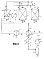
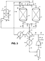
- Figures 1 to 3 are each a simplified flow diagram of a plant for production of 1,4-cyclohexanedimethanol in two hydrogenation reactors connected in parallel by hydrogenation of dimethyl 1,4-cyclohexanedicarboxylate; and
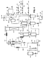
- Figure 4 is a simplified flow diagram of an experimental apparatus for production of 1,4-cyclohexanedimethanol in a single hydrogenation zone by hydrogenation of dimethyl 1,4-cyclohexanedicarboxylate.
- It will further be understood by those skilled in the art that the drawings are diagrammatic and that further items of equipment such as temperature and pressure sensors, pressure relief valves, control valves, level controllers and the like would additionally be required in a commercial plant. The provision of such ancillary items of equipment forms no part of the present invention and is in accordance with conventional chemical engineering practice. Moreover it is not intended that the scope of the invention should be limited in any way by the precise methods of heating, vaporising and condensing various process streams or by the arrangement of heaters, heat exchangers, vaporising or condensing apparatus provided therefor. Any suitable arrangement of equipment other than those depicted in the drawings which fulfils the requirements of the invention may be used in place of the illustrated equipment in accordance with conventional chemical engineering techniques.
- Referring to Figure 1 of the drawings, a technical grade of dimethyl 1,4-cyclohexanedicarboxylate is supplied in line 1, in a first phase of operation, to a
vaporiser nozzle 2 located in an upper part of avaporiser vessel 3 above a bed of packing 4. A stream of hot hydrogen-containing gas is supplied to the bottom ofvaporiser vessel 3 inline 5. A saturated vaporous mixture comprising dimethyl 1,4-cyclohexanedicarboxylate is recovered inline 6 from the top ofvaporiser vessel 3. The resulting vaporous mixture is mixed with further hot hydrogen-containing gas fromline 7 under the control ofvalve 8. The combined stream which now has a gas:dimethyl 1,4-cyclohexanedicarboxylate molar ratio of about 400:1 and is at a pressure of about 900 psia (about 62.05 bar) and at a temperature of about 230°C, is fed by way ofvalve 9 andline 10 to ahydrogenation reactor 11 which contains a bed of a pelletedheterogeneous hydrogenation catalyst 12, such as reduced copper chromite or the chromium-free catalyst designated DRD92/89. The hydrogenation reaction product mixture exitsreactor 11 vialine 13 and passes throughvalve 14 to enterline 15. The hydrogenation reaction product mixture inline 15 is cooled inheat interchanger 16 and the resulting partially condensed mixture passes on inline 17 through cooler 18 in which it is further cooled. The resulting mixture of gas and condensate flows on inline 19 to a gas-liquid separator 20 from which a mixture of methanol and crude 1,4-cyclohexanedimethanol is recovered inline 21. The uncondensed gaseous mixture inline 22 comprises unreacted hydrogen together with inert gases and methanol vapour and is compressed by means ofcompressor 23 to give a compressed gas stream inline 24. - The compressed recycled gas in
line 24 is combined with make-up hydrogen-containing gas fromline 25. The combined mixture inline 26 is heated by passage throughheat exchanger 16 and flows on inline 27 toheater 28 in which its temperature is raised further to a suitable temperature for effecting vaporisation of the dimethyl 1,4-cyclohexanedicarboxylate feed. The resulting hot gas inline 29 is then divided into two streams, one being the stream inline 5 and the other being a stream inline 30. This latter stream is heated further inheater 31 to a temperature of about 240°C and passes on by way ofline 32,valve 33 andlines second hydrogenation reactor 36 which, in this first phase of operation, is in reactivation mode.Reactor 36 contains a charge ofhydrogenation catalyst 37. The hot gas exiting the top ofreactor 36 inline 7 is admixed, as already described above, with the saturated vaporous mixture inline 6 to increase the hydrogen:dimethyl 1,4-cyclohexanedicarboxylate molar ratio therein and to raise its temperature above its dew point, e.g. at least 5°C to 10°C above its dew point. - The plant also includes
lines valves Line 42 indicates a line by means of which a stream containing any "heavies" collecting in the bottom ofvaporiser vessel 3 can be drawn off.Reference numeral 43 indicates a purge gas line through which a purge gas stream can be taken in order to limit the build up of inert gases in the circulating gas. Such inert gases may enter the plant in the make up gas stream inline 25. - After a period of operation the activity of the
catalyst charge 12 will have declined to a point at which reactivation is desirable. Although the reasons for catalyst deactivation have not been clarified, it can be postulated that a possible cause of this loss of catalyst activity is the formation of traces of involatile polyesters on the catalyst surface due to ester exchange reactions between, for example, dimethyl 1,4-cyclohexanedicarboxylate, on the one hand, and 1,4-cyclohexanedimethanol, or methyl 4-hydroxymethylcyclohexanecarboxylate, which can be postulated to be an intermediate product of the hydrogenation reaction, or hydroxymethylcyclohexylmethyl 1,4-cyclohexanedicarboxylate, which is the ester interchange product between dimethyl 1,4-cyclohexanedicarboxylate and 1,4-cyclohexanedimethanol, on the other hand. The resulting di- or trimeric materials can then undergo further reaction with components of the vaporous mixture to cause these oligomeric chains to grow. Polyethers and mixed polyethers-polyesters can also be formed. - Such polymeric byproducts on the catalyst surface are susceptible to hydrogenation. Hence reactivation of the catalyst by treatment with a hot hydrogen-containing gas is possible. It has further been shown in the course of experimental work to investigate the hydrogenation of dimethyl 1,4-cyclohexanedicarboxylate which forms the background to the present invention that, for whatever reason, the passage of a hot stream of hydrogen-containing gas over partially deactivated catalyst has a beneficial effect in at least partially restoring the activity of the catalyst.
- Accordingly in a second phase of
operation valve 33 is shut andvalve 41 is opened, whilevalve 14 is closed andvalve 40 is opened. In this way hydrogenationreactor 36 with its fresh or reactivatedcatalyst charge 37 is brought on line, whilstreactor 11 goes into reactivation mode and its partially deactivated charge ofcatalyst 12 is reactivated. In this second mode of operation the saturated vaporous mixture inline 6 is mixed with hot hydrogen-containing gas fromline 10 to form a vaporous feed mixture which flows inline 7 throughreactor 36 and itscatalyst charge 37. The resulting reaction mixture passes by way oflines valve 40 toline 15. The hot hydrogen-containing gas fromline 32 passes throughvalve 41 toline 39 and then throughline 13 to the bottom ofhydrogenation reactor 11. - When the
catalyst charge 37 has become deactivated to some extent thevalves hydrogenation reactors - The above described steps can be repeated as often as may be expedient, bringing the
reactors - The make-up gas in
line 25 can be a mixture of hydrogen, optional minor amounts of components such as CO and CO2, and inert gases, such as argon, nitrogen, or methane, containing at least about 70 mole % of hydrogen. Preferably the make-up gas contains at least 90 mole %, and even more preferably at least 97 mole %, of hydrogen. The make-up gas can be produced in any convenient manner, e.g. by partial oxidation or steam reforming of natural gas followed by the water gas shift reaction, and CO2 absorption, followed possibly by methanation of at least some of any residual traces of carbon oxides. Pressure swing absorption can be used if a high purity hydrogen make-up gas is desired. - At start up of the plant the
reactors reactors catalyst beds vaporiser vessel 3 and toreactor 11 have been achieved the flow of dimethyl 1,4-cyclohexanedicarboxylate in line 1 is commenced to bring the plant on line in the first phase of operation. - In Figure 2 of the drawings the same reference numerals have been used as in Figure 1 to denote like items of equipment. Whereas the hydrogen-containing gas flows in the plant of Figure 1 through the
catalyst bed same bed particular bed - In the plant of Figure 2 hot gas from the stream in
line 32 can be fed either viavalve 51 andline 52 intoline 7 and then throughreactor 36 or viavalve 53 andline 54 intoline 10 and then throughreactor 11. Ifreactor 11 is in on line mode withvalve 8 closed andreactor 36 is in reactivation mode, thenvalve 51 is adjusted so that most of the gas fromline 32 flow throughvalve 51 intoreactor 36 and only sufficient gas passes throughvalve 53 intoline 10 to raise the feed temperature toreactor 11 above its dew point. To bringreactor 36 into online mode valve 9 is closed andvalve 8 is opened, whereuponvalve 51 is closed somewhat andvalve 53 is opened a corresponding amount to cause most of the gas fromline 32 to flow throughreactor 11 while only sufficient gas passes throughvalve 51 to satisfy dew point requirements. - In the plant of Figure 2 any volatile potential catalyst deactivating materials released in the reaction mode do not pass through the on line catalyst charge and can be recovered in the product stream in
line 21. Although preliminary indications are that no such catalyst deactivating materials are released when the unsaturated organic compound being hydrogenated is dimethyl 1,4-cyclohexanedicarboxylate, this may not be the case when other unsaturated organic compounds are being hydrogenated. - Figure 3 illustrates a further design of hydrogenation plant in accordance with the invention. In this plant, as in the plant of Figure 2, the direction of gas flow through each of the
catalyst beds - In the plant of Figure 3 the hydrogen-containing gas supplied in
line 5 for vaporisation of the incoming dimethyl 1,4-cyclohexanedicarboxylate feed in line 1 is passed first through one of thecatalyst beds reactor 36 is in reactivation mode, most of the hot gas inline 29 is fed throughvalve 51 andline 52 intoreactor 36 throughcatalyst charge 37, and passes out vialine 35 and valve 61 toline 5.Valves valve 53 is open only so far as is necessary to permit passage of sufficient gas intoline 10 to satisfy dew point requirements. Meanwhile the vaporous feed mixture inline 6 passes throughvalve 9 and vialine 10 intoreactor 11 whosecatalyst charge 12 is in on line mode. The product stream inline 13 flows throughvalve 14 intoline 15,valve 62 being closed. When it is desired to bringcatalyst charge 37 on line and to reactivatecatalyst charge 12 inreactor 11,valves open valves Valve 53 is opened somewhat and the gas flow throughvalve 51 is reduced to the extent necessary for dew point considerations. To revert to the former condition withcatalyst charge 37 being reactivated andcatalyst charge 12 being on line again, the conditions of the various valves are each readjusted to its respective former condition. This procedure can be repeated one or more further times as may be expedient bringing thereactors - It will be understood by those skilled in the art that, whilst dimethyl 1,4-cyclohexanedicarboxylate has been chosen as a suitable material with which to exemplify the process of the invention, the process of the invention is by no means limited in its application to hydrogenation reactions involving dimethyl 1,4-cyclohexanedicarboxylate and may, in fact, be applied to many vapour phase hydrogenation reactions using esters, diesters or lactones as feedstocks, in which involatile hydrogenatable byproducts are formed and deposited on the catalyst surface, for example hydrogenation of dimethyl or diethyl maleate to yield butane-1,4-diol.
- The invention is further described with reference to the following Examples. The compositions of copper-containing catalysts A and B used in the Examples are listed in Table I. The oxygen content of the catalyst has been omitted in each case.
TABLE I Catalyst Composition wt% Surface area m2/g Density g/cm3 Pore Volume mm3/g Cu Cr Zn Mn Ba Al A DRD89/21 57.6 19.0 <0.01 0.09 <0.01 <0.01 28 1.420 200 B DRD92/89 41.1 0.26 <0.01 6.4 <0.01 20.4 47.1 1.452 211 - The hydrogenation of a technical grade of dimethyl 1,4-cyclohexanedicarboxylate was investigated using the experimental apparatus illustrated in Figure 4.
- The composition of the technical grade feed was: 34.47 wt% trans-dimethyl 1,4-cyclohexanedicarboxylate, 62.61 wt% cis-dimethyl 1,4-cyclohexanedicarboxylate, 1.50 wt% methyl hydrogen 1,4-cyclohexanedicarboxylate of formula


- In a commercial plant, hydrogen gas is separated from the hydrogenation product and is advantageously recycled through the hydrogenation zone. The hydrogen recycle stream will contain a quantity of methanol vapour produced by the hydrogenation of dimethyl 1,4-cyclohexanedicarboxylate. Hence, the vaporous mixture supplied to the hydrogenation zone in a commercial plant will generally contain methanol in addition to hydrogen and an unsaturated organic compound. In order that the experimental rig described hereinbelow should accurately predict the results obtained during commercial operation, the liquid feed supplied to the vaporiser was supplemented by a quantity of liquid methanol corresponding to the quantity of methanol which would be contained in the recycle hydrogen stream in a commercial plant. Although hydrogen is recycled in the experimental rig described hereinbelow, the quantity of methanol contained within the recycle hydrogen stream is proportionately less than would be contained in a corresponding commercial recycle stream. This difference arises because the recycle gas in the experimental rig is cooled substantially below the temperature to which it would be desirably cooled in a commercial plant. More methanol is therefore "knocked out" of the experimental recycle hydrogen stream. This discrepancy between the experimental rig and a commercial plant is necessitated by the delicacy of the equipment, particularly the analytical equipment, used in the experimental rig. In these Examples, methanol is added to the experimental liquid feed in a quantity which is substantially equal to the proportionate quantity of methanol which would be present in the experimental recycle stream if the rig were operated under commercial conditions minus the quantity of methanol actually present in the experimental recycle hydrogen stream. In the Examples, all parameters such as conversion rates and hourly space velocities are calculated on a methanol free basis.
- The experimental apparatus is illustrated in Figure 4. An approximately 70 wt% solution of the technical grade of dimethyl 1,4-cyclohexanedicarboxylate in methanol is fed from
reservoir 100 by way ofvalve 101,line 102 andvalve 103 toliquid feed pump 104.Burette 105 provides a buffer supply whilstburette 106 is fitted with a liquid level controller (not shown) that controlsvalve 101 so as to ensure that liquid feed is supplied fromreservoir 100 toliquid feed pump 104 at a constant head. The liquid feed is pumped throughnon-return valve 107 andisolation valve 108 intoline 109, which can be heated byelectrical heating tape 110, before the heated liquid enters the upper part of aninsulated vaporiser vessel 111 above a bed of 6mm x 6mm glass rings 112. A stainlesssteel demister pad 113 is fitted at the top end of thevaporiser vessel 111. A stream of hot hydrogen-containing gas is supplied to the bottom ofvaporiser 111 inline 114. Aliquid drain line 115 fitted with adrain valve 116 enables withdrawal of any unvaporised liquid feed material (e.g. "heavies") from the base of thevaporiser vessel 111. The vaporisation of the liquid feed supplied to thevaporiser vessel 111 is assisted byheating tape 117. A saturated vaporous mixture comprising dimethyl 1,4-cyclohexanedicarboxylate and hydrogen is recovered inline 118 from the top ofvaporiser vessel 111. The vaporous mixture is heated byheating tape 119 in order to raise its temperature above the dew point of the mixture prior to entering the top end ofhydrogenation reactor 120 which contains a bed of 300 ml (428.1 g) of a pelleted copperchromite hydrogenation catalyst 121. The catalyst was catalyst A of Table I. Glass rings are packed inreactor 120 above and below thecatalyst bed 121. The vaporous mixture passes downward throughcatalyst bed 121 where conversion of dimethyl 1,4-cyclohexanedicarboxylate to 1,4-cyclohexanedimethanol occurs under adiabatic conditions. Adiabaticity is maintained by electrical heating tapes (not shown) embedded within insulation aroundreactor 120 under the control of appropriately positioned thermocouples (not shown). The overall reaction is mildly exothermic with a general increase in catalyst bed temperature of approximately 1 to 2°C. The hydrogenation product mixture exits thehydrogenation reactor 120 inline 122 and is passed throughheat exchanger 123 which simultaneously cools the hydrogenation product mixture and heats a supply of hydrogen-containing gas fromline 124. Condensation of the bulk of the 1,4-cyclohexanedimethanol inline 122 occurs inheat exchanger 123. The gas inline 124 comprises hydrogen-containing gas fromline 125 and, optionally, an inert gas or a mixture of inert gases such as nitrogen, argon or methane supplied inline 126. The gas inline 125 comprises make-up hydrogen supplied inline 127 and recycle hydrogen supplied inline 128. Make-up hydrogen inline 127 may be supplied toline 125 in either or both of two streams inlines pressure controllers 131 to 136 and amass flow controller 137 from high purity hydrogen cylinders (not shown). - The heated hydrogen-containing gas from
heat exchanger 123 passes on inline 114 and is heated further byelectrical heating tape 138 for supply to thevaporiser vessel 111. - The cooled hydrogenation product from
heat exchanger 123 passes on throughline 139 to be cooled further in cooler 140 to a temperature near ambient temperature. The liquid/vapour mixture from cooler 140 passes on inline 141 to afirst knockout pot 142 where liquid hydrogenation product is collected for eventual supply by means ofvalve 143,line 144 andcontrol valve 145 toproduct line 146. A vaporous mixture comprising hydrogen and uncondensed methanol exits the top ofknockout pot 142 inline 147 and is further cooled to a temperature of 10°C in cooler 148. The further cooled liquid/vapour mixture from cooler 148 is supplied vialine 149 to asecond knockout pot 150 wherein condensed methanol is collected for eventual supply throughvalve 151 andline 152 toproduct line 146. The gas and uncondensed materials fromknockout pot 150 are supplied vialine 153 throughsuction pot 154 intoline 155 and then throughvalve 156 togas recycle compressor 157. Gas is recycled throughvalve 158lines vaporiser 111. In order to control the concentration of inert gases, such as nitrogen, in the circulating gas a purge gas stream may be bled from the system inline 159 under the control ofvalve 160. -
Reference numeral 161 indicates a bypass valve. - At start up of the apparatus the charge of copper-containing catalyst was placed in
reactor 120 which was then purged with nitrogen. The catalyst charge was then reduced according to the teachings of EP-A-0301853. - Technical grade dimethyl 1,4-cyclohexanedicarboxylate, appropriately diluted with methanol, was then pumped to the
vaporiser 111 at a feed rate corresponding to an appropriate liquid hourly space velocity. The feed temperature, feed pressure and gas:dimethyl 1,4-cyclohexanedicarboxylate molar ratio in the vaporous mixture inline 118 were selected so that the hydrogenation zone was operated under conditions which prevented the condensation of both dimethyl 1,4-cyclohexanedicarboxylate and the less volatile 1,4-cyclohexanedimethanol product. The temperature in the hydrogenation zone was above the dew point of the vaporous feed mixture at the operating pressure. - The liquid in
line 146 was analysed periodically by capillary gas chromatography using a 15 m long, 0.32 mm internal diameter fused silica column coated internally with a 0.25 µm film of DB wax, a helium flow rate of 2 ml/minute with a gas feed split ratio of 100:1 and a flame ionisation detector. The instrument was fitted with a chart recorder having a peak integrator and was calibrated using a commercially available sample of dimethyl 1,4-cyclohexanedicarboxylate of known composition. The exit gas was also sampled and analysed by gas chromatography using the same technique. The identities of the peaks were confirmed by comparison of the retention times observed with those of authentic specimens of the materials in question and by mass spectroscopy. Included amongst the compounds detected in the reaction mixture were 1,4-cyclohexanedimethanol, dimethyl 1,4-cyclohexanedicarboxylate, 4-methoxymethyl cyclohexanemethanol, di-(4-methoxymethylcyclohexylmethyl) ether, and methanol. Operation of the rig was monitored over a period of several weeks. From the results obtained it appeared that over this period dimethyl 1,4-cyclohexanedicarboxylate had been converted in excess of 99%, with a selectivity to 1,4-cyclohexanedimethanol of approximately 98.5% being obtained, the balance being minor by-products. After making due allowance for the methanol present in the feed solution of dimethyl 1,4-cyclohexanedicarboxylate fromreservoir - After further operation of the rig the conversion of dimethyl 1,4-cyclohexanedicarboxylate was found to be 97.53% under the conditions specified for Example 1 in Table II below, the selectivity to 1,4-cyclohexanedimethanol being 96.89%. The operating conditions were subsequently altered to those listed under Example 2 in Table II. Operation of the rig was continued for a number of days over the course of which it was necessary to raise the feed temperature by 3°C in order to maintain the desired conversion of dimethyl 1,4-cyclohexanedicarboxylate. The results observed are listed under Example 3 in Table II. A further period of continuous operation of the rig ensued during which the activity declined over the course of several weeks, as evidenced by the increase in feed temperature of 6°C, compared with Example 2, necessary to maintain the conversion of dimethyl 1,4-cyclohexanedicarboxylate as near as possible the desired value. The results at this time are given under Example 4. Operation was continued for a few days more. Then the conditions were changed to those set out in Table II under Example 5, which are comparable to those specified for Example 1. Compared with Example 1 the conversion had dropped over the intervening period of operation from 97.53% to 85.47%, thus demonstrating that a very significant loss of catalyst activity had occurred. The dimethyl 1,4-cyclohexanedicarboxylate feed was then turned off and, after an interval of approximately 3 hours, the feed temperature to
reactor 120 was increased to 250°C and hydrogen gas was passed through thereactor 120 at this temperature for 14 hours in order to effect catalyst reactivation. Thereactor 120 was then returned to the same conditions as those which prevailed immediately prior to the reactivation step. The dimethyl 1,4-cyclohexanedicarboxylate conversion immediately after catalyst reactivation had occurred was 91.86% as reported in Example 6, demonstrating that at least partial reactivation had been successfully accomplished. This was confirmed by restoring the operating conditions substantially to those of Example 4. The conversion had been increased from 98.61%, as reported in Example 4, to 99.79%, as reported in Example 7, at a feed temperature of 236°C. - Comparison of Examples 1, 5 and 6 shows that in the interval between Examples 1 and 5 the catalyst had dropped in activity from an arbitrary relative activity value of 100% in Example 1, as measured by conversion of dimethyl 1,4-cyclohexanedicarboxylate, to a relative catalyst activity of 87.63%, measured on the same basis in Example 5. After the reactivation procedure the relative catalyst activity, as reported in Example 6, had been restored to 94.19% of the original value.
TABLE II Example No. Inlet Temp. °C Gas:DMCD Molar ratio LHSV h-1 Pressure psia (bar) DMCD conversion mol% Selectivity mol % CHDM BYPR METH DETH 1 220 691 0.42 900 (62.05) 97.53 96.89 2.75 0.14 0.14 2 230 381 0.31 903 (62.26) 98.99 96.50 3.20 0.19 0.11 3 233 340 0.31 903 (62.26) 99.06 96.54 3.16 0.19 0.11 4 236 354 0.30 906 (62.47) 98.61 96.46 3.24 0.21 0.09 5 220 716 0.42 900 (62.05) 85.47 96.63 3.15 0.11 0.11 6 219 715 0.41 900 (62.05) 91.86 96.78 2.85 0.11 0.17 7 236 330 0.29 901 (62.12) 99.79 95.74 3.84 0.24 0.18 Notes to Table II:
DMCD = dimethyl 1,4-cyclohexanedicarboxylate
LHSV = liquid hourly space velocity
CHDM = 1,4-cyclohexanedimethanol
BYPR = miscellaneous byproducts
METH = 4-methoxymethyl cyclohexanemethanol
DETH = di-(4-hydroxymethylcyclohexylmethyl) ether
Gas = hydrogen containing gas containing more than 98% hydrogen. - The general procedure of Examples 1 to 7 is repeated using dimethyl maleate, diethyl maleate, diethyl succinate, dimethyl fumarate, or gamma-butyrolactone in place of dimethyl 1,4-cyclohexane-dicarboxylate, resulting in each case in production of butane-1,4-diol. A similar improvement in catalyst activity is observed following the reactivation procedure.
- The general procedure of Examples 1 to 7 is repeated except that catalyst A is replaced by catalyst B with similarly good results.
- An experimental rig is designed for use in a process intended to be operated in a plant of the type depicted in Figure 1. This rig is essentially identified to that of Figure 4 except that
reactor 120 is replaced by a pair of reactors in series. The same general procedure is followed as described in respect of Examples 1 to 7, with a first reactor on line and maintained under conditions effective to hydrogenate the vaporous feed mixture supplied thereto and a second reactor in standby or reactivation mode with no hydrogenatable material supplied thereto. A gradual deactivation of the catalyst charge contained within the first reactor is observed, substantially as exemplified in Examples 1 to 7. In order to reactivate the catalyst charge within the first reactor, the vaporous feed mixture supplied thereto is diverted into the second reactor, thereby to allow continuation of the hydrogenation reaction in the second reactor. Meanwhile, the first reactor is supplied with a hydrogen-containing gas thereby to reactivate the catalyst charge therein. After a period of operation during which the catalyst activity in the second reactor declines in a manner similar to the deactivation of the catalyst within a single hydrogenation reactor recorded in Examples 1 to 7, the vaporous feed mixture is switched back to the first reactor thereby to allow continuation of the hydrogenation reaction whilst the reactivation procedure is performed on the second reactor. The activity of the hydrogenation catalyst in the first reactor is seen to be significantly increased in a manner similar to that reported for a single hydrogenation zone. The overall procedure is repeated several times with excellent maintenance of conversion of dimethyl 1,4-cyclohexanedicarboxylate.
Claims (19)
- A process for the production of a hydroxylic compound selected from alcohols and diols by hydrogenation of a corresponding organic compound possessing a carbon-to-oxygen double bond and being selected from esters, diesters and lactones which comprises:(a) providing at least two hydrogenation zones, each containing a charge of a granular hydrogenation catalyst effective for catalysing the hydrogenation of the organic compound to the hydroxylic compound;(b) supplying to at least one of the hydrogenation zones, in a first phase of operation, a vaporous feed stream comprising a hydrogen-containing gas and the organic compound;(c) maintaining the at least one hydrogenation zone, in the first phase of operation, under temperature and pressure conditions conducive to hydrogenation of the organic compound to yield the hydroxylic compound;(d) recovering from the at least one hydrogenation zone, in the first phase of operation, a reaction product stream comprising the hydroxylic compound;(e) supplying to at least one other hydrogenation zone, in the first phase of operation, a stream of hydrogen-containing gas thereby to reactivate the charge of hydrogenation catalyst therein;(f) supplying to the at least one other hydrogenation zone, in a second phase of operation, a vaporous feed stream comprising a hydrogen-containing gas and the organic compound;(g) maintaining the at least one other hydrogenation zone, in the second phase of operation, under temperature and pressure conditions conducive to hydrogenation of the organic compound to the hydroxylic compound;(h) recovering from the at least one other hydrogenation zone, in the second phase of operation, a reaction product stream comprising the hydroxylic compound; and(i) supplying to the at least one hydrogenation zone, in the second phase of operation, a stream of hydrogen-containing gas thereby to reactivate the charge of hydrogenation catalyst therein.
- A process according to claim 1, in which the stream of hydrogen-containing gas of at least one of steps (e) to (i) comprises a hot stream of recycle and make-up gas.
- A process according to claim 1 or claim 2, in which there is recovered from at least one of steps (e) and (i) a stream of hydrogen-containing gas which is admixed with a vaporous hydrogen-containing stream of the organic compound to form the vaporous feed stream of the corresponding one of steps (b) and (f).
- A process according to claim 1 or claim 2, in which there is recovered from at least one of steps (e) and (i) a stream of hydrogen-containing gas which is admixed with the reaction product stream of the corresponding one of steps (d) and (h).
- A process according to claim 1 or claim 2, in which there is recovered from at least one of steps (e) and (i) a stream of hydrogen-containing gas which is used to vaporise the organic compound and to form a vaporous hydrogen-containing stream of the organic compound.
- A process according to any one of claims 1 to 5, in which the vaporous feed stream of at least one of steps (b) and (f) is formed by admixing hot recycle gas with a vaporous hydrogen-containing stream of the organic compound.
- A process according to claim 6, in which the vaporous hydrogen-containing stream of the organic compound of steps (b) and (f) is substantially saturated with the organic material.
- A process according to any one of claims 1 to 7, in which the vaporous feed stream of at least one of steps (b) and (f) is at a feed temperature at least about 5°C above its dew point.
- A process according to any one of claims 1 to 8, in which the direction of flow of the stream of hydrogen-containing gas through the respective hydrogenation zone or zones in at least one of steps (e) and (i) is the same as the direction of flow of the vaporous feed stream through that zone in the corresponding one of steps (b) and (f).
- A process according to any one of claims 1 to 8, in which the direction of flow of the stream of hydrogen-containing gas through the respective hydrogenation zone or zones in at least one of steps (e) and (i) is the opposite to the direction of flow of the vaporous feed stream through that zone in the corresponding one of steps (b) and (f).
- A process according to any one of claims 1 to 10, in which the temperature and pressure conditions conducive to hydrogenation of the unsaturated organic compound comprise a temperature of from 150°C to 350°C and a pressure of from 150 psia (10.34 bar) to 2000 psia (137.90 bar).
- A process according to any one of claims 1 to 11, in which the organic compound is selected from (C1 to C4 alkyl) esters of C8 to C22 monocarboxylic acids, di-(C1 to C4 alkyl) esters of dicarboxylic acids containing at least 4 carbon atoms, and lactones of hydroxyacids containing from 4 to 16 carbon atoms.
- A process according to any one of claims 1 to 12, in which the organic compound comprises dimethyl 1,4-cyclohexanedicarboxylate and in which the hydrogenated product comprises 1,4-cyclohexanedimethanol.
- A process according to any one of claims 1 to 12, in which the organic compound comprises dimethyl 1,2-cyclohexanedicarboxylate and in which the hydrogenated product comprises 1,2-cyclohexanedimethanol.
- A process according to any one of claims 1 to 12, in which the organic compound comprises dimethyl 1,3-cyclohexanedicarboxylate and in which the hydrogenated product comprises 1,3-cyclohexanedimethanol.
- A process according to any one of claims 1 to 12, in which the organic compound comprises an ester selected from dimethyl and diethyl maleate and in which the hydrogenated product comprises-butane-1,4-diol.
- A process according to any one of claims 1 to 16, in which the period used for reactivation ranges from 1 hour up to 24 hours.
- A process according to any one of claims 1 to 17, in which the reactivation temperature of step (e) lies in the range of from 150°C to 350°C and is from 50°C less than to 50°C more than the feed temperature of the vaporous feed stream to the hydrogenation zone.
- A process according to any one of claims 1 to 18, in which the catalyst is selected from reduced copper chromite, reduced promoted copper chromite, and manganese promoted copper catalysts.
Applications Claiming Priority (2)
| Application Number | Priority Date | Filing Date | Title |
|---|---|---|---|
| GB939324786A GB9324786D0 (en) | 1993-12-02 | 1993-12-02 | Process |
| GB9324786 | 1993-12-02 |
Publications (2)
| Publication Number | Publication Date |
|---|---|
| EP0656338A1 EP0656338A1 (en) | 1995-06-07 |
| EP0656338B1 true EP0656338B1 (en) | 1997-12-03 |
Family
ID=10746059
Family Applications (1)
| Application Number | Title | Priority Date | Filing Date |
|---|---|---|---|
| EP94300075A Expired - Lifetime EP0656338B1 (en) | 1993-12-02 | 1994-01-06 | Vapour phase hydrogenation of esters or lactones to hydroxy compounds |
Country Status (9)
| Country | Link |
|---|---|
| US (1) | US5395991A (en) |
| EP (1) | EP0656338B1 (en) |
| JP (1) | JP4050334B2 (en) |
| KR (1) | KR100282969B1 (en) |
| AT (1) | ATE160767T1 (en) |
| DE (1) | DE69407146T2 (en) |
| ES (1) | ES2111845T3 (en) |
| GB (1) | GB9324786D0 (en) |
| TW (1) | TW276247B (en) |
Families Citing this family (21)
| Publication number | Priority date | Publication date | Assignee | Title |
|---|---|---|---|---|
| US5475160A (en) * | 1994-11-07 | 1995-12-12 | Shell Oil Company | Process for the direct hydrogenation of triglycerides |
| US5463143A (en) * | 1994-11-07 | 1995-10-31 | Shell Oil Company | Process for the direct hydrogenation of wax esters |
| US5475159A (en) * | 1994-11-07 | 1995-12-12 | Shell Oil Company | Process for the direct hydrogenation of methyl esters |
| US5536889A (en) * | 1995-09-29 | 1996-07-16 | Shell Oil Company | Process for the two-stage hydrogenation of methyl esters |
| JP3337615B2 (en) * | 1997-03-03 | 2002-10-21 | 花王株式会社 | Method for producing alcohol |
| US6455742B1 (en) | 1999-09-02 | 2002-09-24 | Wisconsin Alumni Research Foundation | Method for catalytically reducing carboxylic acid groups to hydroxyl groups in hydroxycarboxylic acids |
| DK1556320T3 (en) * | 2002-11-01 | 2015-06-08 | Novozymes As | PROCEDURE FOR PREPARING 1,3-PROPANDIOL |
| US7084180B2 (en) * | 2004-01-28 | 2006-08-01 | Velocys, Inc. | Fischer-tropsch synthesis using microchannel technology and novel catalyst and microchannel reactor |
| US6919489B1 (en) | 2004-03-03 | 2005-07-19 | Eastman Chemical Company | Process for a cyclohexanedimethanol using raney metal catalysts |
| EP2200958B1 (en) * | 2007-08-31 | 2015-11-04 | Basf Se | Method for producing 1,2-propandiol by hydrogenating glycerine in a two-step reactor cascade |
| US8581010B2 (en) * | 2011-05-04 | 2013-11-12 | John E. Stauffer | Formation of ethanol from methanol |
| US9108895B2 (en) | 2012-10-26 | 2015-08-18 | Eastman Chemical Company | Promoted ruthenium catalyst for the improved hydrogenation of carboxylic acids to the corresponding alcohols |
| US9115155B1 (en) | 2014-03-20 | 2015-08-25 | Eastman Chemical Company | Low-pressure synthesis of cyclohexanedimethanol and derivatives |
| JP2017524718A (en) * | 2014-08-15 | 2017-08-31 | エクソンモービル ケミカル パテンツ インコーポレイテッド | Method and system for producing cyclohexanone |
| US10493397B2 (en) | 2015-07-14 | 2019-12-03 | John E. Stauffer | Carbon dioxide recovery |
| US10293304B2 (en) | 2015-07-14 | 2019-05-21 | John E. Stauffer | Carbon dioxide recovery using an absorption column in combination with osmotic filters |
| US10040737B2 (en) | 2015-07-14 | 2018-08-07 | John E. Stauffer | Methanol production from methane and carbon dioxide |
| KR102223388B1 (en) | 2017-09-29 | 2021-03-04 | 한화솔루션 주식회사 | Preparation method of ruthenium-platinum-tin catalyst for hydrogenation of cyclohexane dicarboxylic acid (CHDA) and method for producing cyclohexane dimethanol (CHDM) using said catalyst |
| JP6786054B2 (en) * | 2017-12-18 | 2020-11-18 | 株式会社豊田中央研究所 | Methane production equipment and methane production method using it |
| KR102188755B1 (en) | 2017-12-22 | 2020-12-08 | 한화솔루션 주식회사 | Preparation method of cyclohexane dimethanol having high trans contents and cyclohexane dimethanol thereof |
| KR102238548B1 (en) | 2017-12-29 | 2021-04-08 | 한화솔루션 주식회사 | Noble metal-transition metal complex catalyst of carbon coated silica-alumina and preparation method of thereof |
Citations (1)
| Publication number | Priority date | Publication date | Assignee | Title |
|---|---|---|---|---|
| WO1991001961A1 (en) * | 1989-08-04 | 1991-02-21 | Davy Mckee (London) Limited | Process |
Family Cites Families (46)
| Publication number | Priority date | Publication date | Assignee | Title |
|---|---|---|---|---|
| US2105664A (en) * | 1930-04-17 | 1938-01-18 | Du Pont | Catalytic hydrogenation of hydroaromatic carboxylic acids and their esters |
| US2137407A (en) * | 1931-05-11 | 1938-11-22 | Du Pont | Catalytic hydrogenation process |
| US2091800A (en) * | 1931-09-15 | 1937-08-31 | Rohm & Haas | Method of hydrogenating esters |
| US2079414A (en) * | 1932-08-20 | 1937-05-04 | Du Pont | Process for producing alcohols from esters of nonaromatic carboxylic acids |
| US2040944A (en) * | 1933-09-22 | 1936-05-19 | Du Pont | Process for producing polyhydroxy alcohols |
| US2755317A (en) * | 1952-11-10 | 1956-07-17 | Universal Oil Prod Co | Hydrogenation of benzene to cyclohexane |
| US2818393A (en) * | 1953-05-05 | 1957-12-31 | Kellogg M W Co | Method of preparing a catalyst |
| US2830095A (en) * | 1953-05-07 | 1958-04-08 | Olin Mathieson | Production of ethylene chlorohydrin |
| BE592181A (en) * | 1955-12-22 | |||
| US2884450A (en) * | 1956-04-20 | 1959-04-28 | Du Pont | Hydrogenation of unsaturated dilactones to 1,8-octanedioic acids and 1,8-octanediolswith copper chromite catalysts |
| US2917549A (en) * | 1958-01-07 | 1959-12-15 | Eastman Kodak Co | Preparation of trans-1,4-cyclohexanedimethanol |
| NL132671C (en) * | 1960-02-09 | |||
| DE1144703B (en) * | 1960-10-06 | 1963-03-07 | Eastman Kodak Co | Process for the preparation of alcohols by catalytic hydrogenation of esters |
| FR1276722A (en) * | 1960-10-11 | 1961-11-24 | Eastman Kodak Co | Process for preparing a catalyst for the reduction of esters to alcohols |
| NL292315A (en) * | 1962-05-05 | |||
| CH438269A (en) * | 1963-05-10 | 1967-06-30 | Snam Spa | Hydrogenation process of acetylenic compounds miscible with water to ethylene compounds |
| US3334149A (en) * | 1964-07-21 | 1967-08-01 | Eastman Kodak Co | Plural stage hydrogenation of dialkyl terephthalate using palladium and then copper chromite |
| US4052467A (en) * | 1967-11-08 | 1977-10-04 | Phillips Petroleum Company | Catalytic reduction of aldehydes to alcohols |
| GB1454440A (en) * | 1974-10-03 | 1976-11-03 | Ucb Sa | Process for the production of butane-1,4-diol from but-2-ene- 1,4-dioic acid |
| GB1464263A (en) * | 1974-12-03 | 1977-02-09 | Ucb Sa | Production of butane-1,4-diol |
| US4032458A (en) * | 1975-08-08 | 1977-06-28 | Petro-Tex Chemical Corporation | Production of 1,4-butanediol |
| US4172961A (en) * | 1975-08-08 | 1979-10-30 | Denka Chemical Corporation | Production of 1,4-butanediol |
| DE2719867A1 (en) * | 1977-05-04 | 1978-11-09 | Bayer Ag | 1,4-Butane-diol prodn. from acrylonitrile and hydrogen cyanide - with conversion of succino-di:nitrile to di:alkyl succinate and hydrogenation |
| DE2845905C3 (en) * | 1978-10-21 | 1983-05-26 | Chemische Werke Hüls AG, 4370 Marl | Process for the continuous production of 1,4-butanediol |
| DE3106819A1 (en) * | 1981-02-24 | 1982-09-09 | Basf Ag, 6700 Ludwigshafen | METHOD FOR PRODUCING 1,4-BUTANDIOL |
| IT1190783B (en) * | 1981-04-29 | 1988-02-24 | Davy Mckee Oil & Chem | PROCESS FOR HYDROGENOLYSIS OF ESTERS OF CARBOXYLIC ACIDS |
| GB8331793D0 (en) * | 1983-11-29 | 1984-01-04 | Davy Mckee Ltd | Process |
| GB8514002D0 (en) * | 1985-06-04 | 1985-07-10 | Davy Mckee Ltd | Process |
| BR8507068A (en) * | 1984-11-21 | 1987-07-14 | Davy Mckee London | PROCESS FOR THE PRODUCTION OF BUTANE-1,4-DIOL |
| GB8514001D0 (en) * | 1985-06-04 | 1985-07-10 | Davy Mckee Ltd | Process |
| US4652685A (en) * | 1985-11-15 | 1987-03-24 | General Electric Company | Hydrogenation of lactones to glycols |
| DE3610698A1 (en) * | 1986-03-29 | 1987-10-01 | Henkel Kgaa | CATALYST AND METHOD FOR THE CATALYTIC HYDRATION OF FATTY ACID METHYL ESTERS IN THE FIXED BED |
| EP0277168A1 (en) * | 1986-08-01 | 1988-08-10 | DAVY McKEE (LONDON) LIMITED | PROCESS FOR THE CO-PRODUCTION OF BUTANE-1,4-DIOL AND $i(GAMMA)-BUTYROLACTONE |
| GB8717989D0 (en) * | 1987-07-29 | 1987-09-03 | Davy Mckee Ltd | Catalyst |
| EP0397650B1 (en) * | 1987-08-03 | 1993-10-27 | Eastman Chemical Company | Low pressure catalytic hydrogenation of carbonyl-containing compounds and catalysts therefor |
| US4837368A (en) * | 1988-02-01 | 1989-06-06 | Eastman Kodak Company | Low pressure catalytic hydrogenation of carbonyl-containing compounds and supported catalysts therefor |
| US4999090A (en) * | 1988-04-10 | 1991-03-12 | Towa Chemical Industry Co., Ltd. | Process for preparing trans-1,4-cyclohexanedimethanol and powder of the same |
| US5185476A (en) * | 1988-07-15 | 1993-02-09 | Eastman Kodak Company | Low pressure catalytic hydrogenation of carbonyl-containing compounds and supported catalysts therefor |
| DE3843956A1 (en) * | 1988-12-24 | 1990-06-28 | Huels Chemische Werke Ag | METHOD FOR PRODUCING ALIPHATIC AND CYCLOALIPHATIC DIOLS BY CATALYTIC HYDRATION OF DICARBONIC ACID ESTERS |
| KR930006046B1 (en) * | 1988-12-28 | 1993-07-03 | 미쓰비시 레이욘 가부시키가이샤 | Polyester copolymer |
| EP0454704B1 (en) * | 1989-01-17 | 1994-09-28 | DAVY McKEE (LONDON) LIMITED | Process for the production of fatty alcohols |
| US4929777A (en) * | 1989-02-13 | 1990-05-29 | Eastman Kodak Company | Catalyst compositions and the use thereof in the hydrogenation of carboxylic acid esters |
| US5142067A (en) * | 1989-12-21 | 1992-08-25 | Union Carbide Chemicals & Plastics Technology Corporation | Hydrogenation with Cu-Al-X catalysts |
| US5191091A (en) * | 1989-12-21 | 1993-03-02 | Union Carbide Chemicals & Plastics Technology Corporation | Hydrogenation with Cu-Al catalysts |
| GB9025708D0 (en) * | 1990-11-27 | 1991-01-09 | Unilever Plc | Fatty ester hydrogenation |
| DE4141199A1 (en) * | 1991-12-13 | 1993-06-17 | Sued Chemie Ag | CHROME-FREE CATALYST FOR HYDRATING ORGANIC COMPOUNDS CONTAINING THE CARBONYL FUNCTIONS |
-
1993
- 1993-12-02 GB GB939324786A patent/GB9324786D0/en active Pending
- 1993-12-30 US US08/175,545 patent/US5395991A/en not_active Expired - Lifetime
- 1993-12-31 TW TW082111217A patent/TW276247B/zh not_active IP Right Cessation
-
1994
- 1994-01-06 KR KR1019940000133A patent/KR100282969B1/en not_active IP Right Cessation
- 1994-01-06 EP EP94300075A patent/EP0656338B1/en not_active Expired - Lifetime
- 1994-01-06 DE DE69407146T patent/DE69407146T2/en not_active Expired - Lifetime
- 1994-01-06 AT AT94300075T patent/ATE160767T1/en not_active IP Right Cessation
- 1994-01-06 ES ES94300075T patent/ES2111845T3/en not_active Expired - Lifetime
- 1994-01-10 JP JP00080094A patent/JP4050334B2/en not_active Expired - Fee Related
Patent Citations (1)
| Publication number | Priority date | Publication date | Assignee | Title |
|---|---|---|---|---|
| WO1991001961A1 (en) * | 1989-08-04 | 1991-02-21 | Davy Mckee (London) Limited | Process |
Also Published As
| Publication number | Publication date |
|---|---|
| EP0656338A1 (en) | 1995-06-07 |
| TW276247B (en) | 1996-05-21 |
| KR950017897A (en) | 1995-07-20 |
| KR100282969B1 (en) | 2001-04-02 |
| GB9324786D0 (en) | 1994-01-19 |
| US5395991A (en) | 1995-03-07 |
| ES2111845T3 (en) | 1998-03-16 |
| JPH07188077A (en) | 1995-07-25 |
| JP4050334B2 (en) | 2008-02-20 |
| ATE160767T1 (en) | 1997-12-15 |
| DE69407146T2 (en) | 1998-04-16 |
| DE69407146D1 (en) | 1998-01-15 |
Similar Documents
| Publication | Publication Date | Title |
|---|---|---|
| EP0656340B1 (en) | Process for the production of hydroxy compounds by hydrogenation of oxygenates | |
| EP0656338B1 (en) | Vapour phase hydrogenation of esters or lactones to hydroxy compounds | |
| EP0656337B1 (en) | Process for the production of 1,4-cyclohexanedimethanol | |
| EP0656339B1 (en) | Process for the production of cyclohexanedimethanol, with preponderance of the trans-isomer | |
| EP0656335B1 (en) | Process for the production of hydroxy compounds by hydrogenation of oxygenates | |
| EP0656336B1 (en) | Process for the production of hydroxy compounds by hydrogenation of oxygenates | |
| EP0656334B1 (en) | Process for the production of cyclohexanedimethanol, with preponderance of the trans-isomer | |
| EP0656341B1 (en) | Process for the production of cyclohexanedimethanol | |
| MXPA94009271A (en) | Process for the production of 1,4-cyclohexanedimethanol | |
| MXPA00010272A (en) | Method for producing mixtures of 1,4-butanediol, tetrahydrofuran and&ggr;-butyrolactone |
Legal Events
| Date | Code | Title | Description |
|---|---|---|---|
| PUAI | Public reference made under article 153(3) epc to a published international application that has entered the european phase |
Free format text: ORIGINAL CODE: 0009012 |
|
| AK | Designated contracting states |
Kind code of ref document: A1 Designated state(s): AT BE CH DE DK ES FR GB GR IE IT LI LU MC NL PT SE |
|
| 17P | Request for examination filed |
Effective date: 19950718 |
|
| 17Q | First examination report despatched |
Effective date: 19960812 |
|
| GRAG | Despatch of communication of intention to grant |
Free format text: ORIGINAL CODE: EPIDOS AGRA |
|
| GRAH | Despatch of communication of intention to grant a patent |
Free format text: ORIGINAL CODE: EPIDOS IGRA |
|
| GRAH | Despatch of communication of intention to grant a patent |
Free format text: ORIGINAL CODE: EPIDOS IGRA |
|
| GRAA | (expected) grant |
Free format text: ORIGINAL CODE: 0009210 |
|
| AK | Designated contracting states |
Kind code of ref document: B1 Designated state(s): AT BE CH DE DK ES FR GB GR IE IT LI LU MC NL PT SE |
|
| PG25 | Lapsed in a contracting state [announced via postgrant information from national office to epo] |
Ref country code: LI Free format text: LAPSE BECAUSE OF FAILURE TO SUBMIT A TRANSLATION OF THE DESCRIPTION OR TO PAY THE FEE WITHIN THE PRESCRIBED TIME-LIMIT Effective date: 19971203 Ref country code: GR Free format text: LAPSE BECAUSE OF FAILURE TO SUBMIT A TRANSLATION OF THE DESCRIPTION OR TO PAY THE FEE WITHIN THE PRESCRIBED TIME-LIMIT Effective date: 19971203 Ref country code: DK Free format text: LAPSE BECAUSE OF NON-PAYMENT OF DUE FEES Effective date: 19971203 Ref country code: CH Free format text: LAPSE BECAUSE OF FAILURE TO SUBMIT A TRANSLATION OF THE DESCRIPTION OR TO PAY THE FEE WITHIN THE PRESCRIBED TIME-LIMIT Effective date: 19971203 Ref country code: AT Free format text: LAPSE BECAUSE OF FAILURE TO SUBMIT A TRANSLATION OF THE DESCRIPTION OR TO PAY THE FEE WITHIN THE PRESCRIBED TIME-LIMIT Effective date: 19971203 |
|
| REF | Corresponds to: |
Ref document number: 160767 Country of ref document: AT Date of ref document: 19971215 Kind code of ref document: T |
|
| REG | Reference to a national code |
Ref country code: CH Ref legal event code: EP |
|
| ITF | It: translation for a ep patent filed |
Owner name: BARZANO' E ZANARDO MILANO S.P.A. |
|
| PG25 | Lapsed in a contracting state [announced via postgrant information from national office to epo] |
Ref country code: LU Free format text: LAPSE BECAUSE OF NON-PAYMENT OF DUE FEES Effective date: 19980106 |
|
| REF | Corresponds to: |
Ref document number: 69407146 Country of ref document: DE Date of ref document: 19980115 |
|
| PG25 | Lapsed in a contracting state [announced via postgrant information from national office to epo] |
Ref country code: IE Free format text: LAPSE BECAUSE OF NON-PAYMENT OF DUE FEES Effective date: 19980203 |
|
| PG25 | Lapsed in a contracting state [announced via postgrant information from national office to epo] |
Ref country code: SE Free format text: LAPSE BECAUSE OF FAILURE TO SUBMIT A TRANSLATION OF THE DESCRIPTION OR TO PAY THE FEE WITHIN THE PRESCRIBED TIME-LIMIT Effective date: 19980303 Ref country code: PT Free format text: LAPSE BECAUSE OF FAILURE TO SUBMIT A TRANSLATION OF THE DESCRIPTION OR TO PAY THE FEE WITHIN THE PRESCRIBED TIME-LIMIT Effective date: 19980303 |
|
| ET | Fr: translation filed | ||
| REG | Reference to a national code |
Ref country code: ES Ref legal event code: FG2A Ref document number: 2111845 Country of ref document: ES Kind code of ref document: T3 |
|
| REG | Reference to a national code |
Ref country code: CH Ref legal event code: PL |
|
| PG25 | Lapsed in a contracting state [announced via postgrant information from national office to epo] |
Ref country code: MC Free format text: LAPSE BECAUSE OF NON-PAYMENT OF DUE FEES Effective date: 19980731 |
|
| PLBE | No opposition filed within time limit |
Free format text: ORIGINAL CODE: 0009261 |
|
| STAA | Information on the status of an ep patent application or granted ep patent |
Free format text: STATUS: NO OPPOSITION FILED WITHIN TIME LIMIT |
|
| 26N | No opposition filed | ||
| REG | Reference to a national code |
Ref country code: GB Ref legal event code: IF02 |
|
| PGFP | Annual fee paid to national office [announced via postgrant information from national office to epo] |
Ref country code: FR Payment date: 20101221 Year of fee payment: 18 |
|
| PGFP | Annual fee paid to national office [announced via postgrant information from national office to epo] |
Ref country code: NL Payment date: 20110117 Year of fee payment: 18 Ref country code: IT Payment date: 20110118 Year of fee payment: 18 |
|
| PGFP | Annual fee paid to national office [announced via postgrant information from national office to epo] |
Ref country code: BE Payment date: 20110221 Year of fee payment: 18 Ref country code: ES Payment date: 20110117 Year of fee payment: 18 |
|
| BERE | Be: lapsed |
Owner name: *EASTMAN CHEMICAL CY Effective date: 20120131 |
|
| REG | Reference to a national code |
Ref country code: NL Ref legal event code: V1 Effective date: 20120801 |
|
| REG | Reference to a national code |
Ref country code: FR Ref legal event code: ST Effective date: 20120928 |
|
| PG25 | Lapsed in a contracting state [announced via postgrant information from national office to epo] |
Ref country code: IT Free format text: LAPSE BECAUSE OF NON-PAYMENT OF DUE FEES Effective date: 20120106 |
|
| PG25 | Lapsed in a contracting state [announced via postgrant information from national office to epo] |
Ref country code: BE Free format text: LAPSE BECAUSE OF NON-PAYMENT OF DUE FEES Effective date: 20120131 Ref country code: FR Free format text: LAPSE BECAUSE OF NON-PAYMENT OF DUE FEES Effective date: 20120131 |
|
| PG25 | Lapsed in a contracting state [announced via postgrant information from national office to epo] |
Ref country code: NL Free format text: LAPSE BECAUSE OF NON-PAYMENT OF DUE FEES Effective date: 20120801 |
|
| PGFP | Annual fee paid to national office [announced via postgrant information from national office to epo] |
Ref country code: GB Payment date: 20121228 Year of fee payment: 20 |
|
| PGFP | Annual fee paid to national office [announced via postgrant information from national office to epo] |
Ref country code: DE Payment date: 20130131 Year of fee payment: 20 |
|
| REG | Reference to a national code |
Ref country code: ES Ref legal event code: FD2A Effective date: 20130705 |
|
| PG25 | Lapsed in a contracting state [announced via postgrant information from national office to epo] |
Ref country code: ES Free format text: LAPSE BECAUSE OF NON-PAYMENT OF DUE FEES Effective date: 20120107 |
|
| REG | Reference to a national code |
Ref country code: DE Ref legal event code: R071 Ref document number: 69407146 Country of ref document: DE |
|
| REG | Reference to a national code |
Ref country code: DE Ref legal event code: R071 Ref document number: 69407146 Country of ref document: DE |
|
| REG | Reference to a national code |
Ref country code: GB Ref legal event code: PE20 Expiry date: 20140105 |
|
| PG25 | Lapsed in a contracting state [announced via postgrant information from national office to epo] |
Ref country code: GB Free format text: LAPSE BECAUSE OF EXPIRATION OF PROTECTION Effective date: 20140105 Ref country code: DE Free format text: LAPSE BECAUSE OF EXPIRATION OF PROTECTION Effective date: 20140108 |