JP4047449B2 - Distributed supply device for combination weigher - Google Patents
Distributed supply device for combination weigher Download PDFInfo
- Publication number
- JP4047449B2 JP4047449B2 JP13285798A JP13285798A JP4047449B2 JP 4047449 B2 JP4047449 B2 JP 4047449B2 JP 13285798 A JP13285798 A JP 13285798A JP 13285798 A JP13285798 A JP 13285798A JP 4047449 B2 JP4047449 B2 JP 4047449B2
- Authority
- JP
- Japan
- Prior art keywords
- layer thickness
- article
- tray
- ring
- shaped frame
- Prior art date
- Legal status (The legal status is an assumption and is not a legal conclusion. Google has not performed a legal analysis and makes no representation as to the accuracy of the status listed.)
- Expired - Lifetime
Links
Images


Description
【0001】
【発明の属する技術分野】
この発明は組合せ秤に設けられている複数の計量槽に対して物品を適切に供給するための分散供給装置に関する。
【0002】
【従来の技術】
複数の計量槽で計量した物品の計量値を種々組合せてその組合せ重量値が目標重量値に等しいか又は近い組合せを選択して、選択された計量槽の物品はそれぞれ排出され、一まとめにされ後段に設けられた包装機により製袋される。現在ではこのような計量方法を行う計量装置としては組合せ秤が広く知られている。この種の計量装置は組合せによって目標とする重量を得るものであるから組合せによる精度(組合せ精度という)というものが、一般の秤で称する計量精度の他に存在し、物品が個々に持っている重量(以下単重という)のバラツキなどにより供給量が異なり組合せ精度が左右されたり、複数ある計量槽に物品を供給するときの1回に供給する供給量の大小などによっても組合せ精度が左右されることが知られている。例えば特開平4−371414においてその一技術が開示されているので紹介する。
【0003】
しかしこの技術では、円形傘状の分散フィーダと称する振動フィーダがありその受け板上の範囲内に円筒状の筒体をほぼ同心円状に設け、この筒体内に上部から供給された物品が分散フィーダの振動により周囲に分散供給され、該筒体内の上下に設けられた光電子センサで筒体内の物品のレベルを常時監視していて下限に達すれば上部の供給コンベアから物品が供給され上限に達すると供給が停止される。そして分散フィーダを除く外部からこの筒体を支持する構造とし、この支持部を上下動させることにより分散フィーダ上の受け板と該筒体下端部との隙間を調整して分散フィーダ上の物品の層厚を加減するものである。そして物品は分散フィーダの外周に放射状に設けられた複数の直進フィーダの搬送台(一般に搬送トレイと称す)に供給され、該複数の直進フィーダの外側に各々の直進フィーダと対応して設けられた計量槽に供給される構造である。このような構造は概略においては現在の組合せ秤では一般的な構造となっていると言える。
【0004】
しかし上述したように分散フィーダの傘状部において層厚調整をしているので一斉に層厚が変えられ大きく供給量が加減できる利点はあるが、本来、上部の供給コンベアからの物品の供給は完全に一様でなく、分散フィーダ上の全方向に同一の層厚ではない何れかの方向に片寄った供給が行われている。これは供給コンベアで搬送されてくる物品の層厚が一定でなく、継続して供給されると言う保証がないからである。つまり供給コンベア上の物品の層厚が多い場合は供給コンベアの進行方向側に多く供給され、又少ないと手前に供給される傾向がある。従って分散フィーダ上の層厚分布が片寄った状態になり、分散フィーダの振動は全周に渡って一様であるから当然放射状に設けられた複数の直進フィーダにもその状態のまま供給されるので直進フィーダ上の層厚も変動する。このために各々の直進フィーダにおいて個別に搬送能力を加減したり、計量槽に物品を供給するための直進フィーダの運転時間を加減するなどして一定の供給量を確保しなければならず、適切なフィーダ制御というものが必要になってくる。しかしこれは組合せ秤の運転プログラムの中を常に変更することとなり、現場での運転者の作業の負担が大きくなる等の問題がある。
【0005】
一方の問題として、供給コンベアからの供給状態は片寄りがなく正常であったとしても、各々の直進フィーダの振幅等にバラツキがあり搬送能力が個々に異なる場合などにおいては、各直進フィーダの搬送能力を考慮して該直進フィーダに供給する物品の量を異ならせて各計量槽への物品の供給量を均一にすることが要求される。又各々の直進フィーダの搬送能力は一様であっても単重のバラツキが少ない場合で各計量槽に均一に供給され過ぎる場合においては各々の直進フィーダへの供給量を意図的に異ならせる必要が生じる。しかし、従来の技術では分散フィーダの上面内で層厚規制をしているのでどうしても一様に流れ込み、これらの要求を満たすことが困難であった。又、絡みやすい物品や付着性のある物品においても同様に各計量槽毎に供給量が異なるので個々に調節できる装置が必要となっていた。
【0006】
【発明が解決しようとする課題】
本発明は上述の問題点に鑑みてなされたものであり、組合せ秤における分散フィーダに物品を供給する場合、その供給状態に片寄りや変動が生じても各々の計量ホッパには確実に所望量の物品を供給することができることと、各々の直進フィーダ毎に物品の層厚が調整ができることにより、各々の計量ホッパに確実に所望量の物品を供給することができること。層厚を安定させ常に均等性を持って分散供給することなどにより組合せ精度の高い組合せ秤を提供することを課題とするものである。
【0007】
【課題を解決するための手段】
前述のような課題を解決するために第1の発明は、螺旋往復振動によって物品を周辺部に搬送する分散フィーダと該分散フィーダの上部に取り付けた円錐形の受け皿と該円錐形の受け皿の外周と重なりを持ち少なくとも等間隔で放射状に配置された複数の直進フィーダに取り付けられており、該直進フィーダの振動により物品を搬送する搬送トレイとにより構成された物品搬送部と、該物品搬送部の内上記複数の直進フィーダの上記搬送トレイ上に位置するように設けられた層厚調整装置であって、該層厚調整装置はリング状の枠体と該リング状の枠体の外周に沿って取り付けられる弾性体より成る層厚規制板と該層厚規制板を上記リング状の枠体に固着するための締付バンドとにより構成されていることを特徴とした組合せ秤用の分散供給装置である。
【0008】
第2発明は螺旋往復運動によって物品を周辺部に搬送する分散フィーダと該分散フィーダの上部に取り付けた円錐形の受け皿と、該円錐形の受け皿の外周と重なりを持ち、少なくとも等間隔で放射状に配置された複数の直進フィーダに取り付けられており該直進フィーダの振動により物品を搬送する搬送トレイとにより構成された物品搬送部と、該物品搬送部の内上記複数の直進フィーダの上記搬送トレイ上に位置するように設けられた層厚調整装置であって、上記層厚調整装置はリング状の枠体と、該リング状の枠体には前記の物品搬送部を構成している前記複数の直進フィーダの前記搬送トレイに対応した数により割り付けられた位置を円周に有し、上記リング状の枠体に割り付けられた位置には上記リング状の枠体の外周曲面に安定して沿うように両端を折り曲げた層厚規制板取付板と弾性体を用いた層厚規制板と上記層厚規制板押え板とを一組とした複数の層厚調節具を上下方向に移動可能にして着脱自在な構造にて取り付けられていることを特徴としている。又、上記リング状の枠体の上記割り付けられた各々の位置に層厚調節具を取り付け締結する手段がそれぞれ単数のボルト及びナットであることも本発明の特徴とするところである。
【0009】
【発明の実施の形態】
以下、本発明の実施の形態を図面に基づいて説明する。
組合せ秤用の分散供給装置を図1及び図2に示す。(A)は分散供給装置の概略断面図、(B)は層厚調整装置の側面図、(C)は分散供給装置の平面図である。分散供給装置の概略の構成は、螺旋往復振動をする振動器1とその上部に固着された円錐形の受け皿2と該受け皿の周辺に少なくとも等間隔に配置された複数の直進フィーダ3とそれに固着された搬送トレイ4と該搬送トレイにそれぞれ対応した位置に搬送トレイからの物品の供給を受ける計量槽を備えた計量部5と搬送トレイ上に位置するようにして、少なくとも分散フィーダ上の円錐形の受け皿の中心と同心円上に配置された層厚調整装置とによるものである。図3は分散供給装置に物品を供給している状態を示す。今、分散フィーダ1の上部受け皿2上に供給コンベア9より物品8を供給すると、物品8は受け皿2上に分散され、供給コンベア9からの落下によって、受け皿の周辺に位置する直進フィーダ3の搬送トレイ4上に達するが分散フィーダの振動により更に均一に分散される。
【0010】
前述したように組合せ秤においては各計量槽に目標重量のほぼ整数分の1の量を1回に供給し計量する。そしてこの計量値を種々組合せて目標重量に等しいか又は近い組合せをコンピュータの演算によって求めるものである。このことから、直進フィーダの搬送トレイ上の物品の層厚や搬送能力及び分散フィーダの受け皿上での層厚や分散供給能力は目標重量が決定されることにより決まり、それぞれ層厚やフィーダの振幅も決まってくる。従って図3に示すように層厚調整装置6により搬送トレイ4上の層厚を規制するが搬送トレイ上の物品の流れは途切れることなく一様に搬送されることが望ましい。そのため層厚調整装置の内側においては搬送トレイの層厚よりも若干多い層厚を確保しておく必要がある。つまり分散フィーダ上の物品の量も常に層厚調整装置により規制できるだけの量が必要になり、分散フィーダ上の層厚をレベルセンサ10により一定量確保している。
【0011】
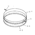
図4は前述の層厚調整装置の第1の実施例であって、6−1はリング状の枠体である。6−2は層厚規制板で例えばウレタンゴムや合成ゴムなどの弾性体を使用した帯状のシートであり片方からスリット(切れ目)を入れた暖簾状でありスリットの深さは物品に応じて適宜決定される。またこのスリットは搬送トレイの山部4−1では変形し隣接する搬送トレイ4のいずれかに分かれる。又、搬送トレイの山部4−1以外にある部分では、変形せずそのままの状態となり物品の層厚規制の役目を果たす。このとき物品の層厚は層厚規制板6−2の最下端と搬送トレイ4の谷部4−2との隙間の寸法を増減することによって行うことができる。6−3は層厚規制板6−2をリング状の枠体6−1に巻き付け固定するための締付バンドである。又、各々の搬送トレイ4全体に渡って層厚を調整する場合はリング状の枠体取付具7の固着位置を上下に変更することにより可能である。
【0012】
図5は前述の層厚調整装置の第2の実施例を示すもので、6−4はリング状の枠体である。6−5は層厚規制板で例えばウレタンゴムや合成ゴムなどの弾性体シートを使用したものである。6−6は層厚規制板の押え板、6−7は層厚規制板取付板で両端を折り曲げた形状である。そして6−8は取付ボルトで6−9は固定用ナットである。これら層厚規制板6−5と押え板6−6及び層厚規制板取付板6−7を一組として層厚調節具6−10を構成し複数組が準備されている。これらの層厚調節具6−10をリング状の枠体に取り付ける順序を図6に図解する。同図において(A)は複数の層厚調節具の内の一つをリング状の枠体から外した図であり(B)はリング状の枠体に取付け固定した図である。図5はその全体を示したものであるが、リング状の枠体6−4の円周に上記の層厚調節具6−10を取り付ける場合は、リング状の枠体6−4の円周を少なくとも、複数の直進フィーダ3の搬送トレイ4に対応した数ににより割り付けられた位置を円周に設けてその位置に層厚調節具は取り付けられる。そして層厚規制板6−5は対応する搬送トレイ4の谷部4−2と一致し各搬送トレイの中央に収まるようになっている。層厚規制板を含む層厚調節具6−10は取付ボルト6−8及び固定用ナット6−9にてリング状の枠体に固着される。本実施例による層厚調整装置の特徴は層厚の調整が各搬送トレイ毎に可能であり、層厚調節具の各々は中央付近の取付穴を長穴にして少なくとも上下に移動できるようになっていることである。更に層厚規制板取付板6−7は両端が折り曲げられているためリング状の枠体の外周に沿いやすく、1本のボルト6−8により取り付けても単独で回転することがない。そして各々の搬送トレイ全体に渡って一様に層厚を調整する場合はリング状の枠体取付具7の固着位置を上下に変更することにより可能である。
【0013】
【発明の効果】
以上のように第1の発明による分散供給装置は、分散フィーダの上部に取り付けた円錐形の受け皿の外周部に放射状に配置した複数の直進フィーダ上の搬送トレイ上に位置するように層厚調整装置を設けたので、分散フィーダの受け皿の上部から供給される物品の供給状態に多少の片寄りや変動が生じても直進フィーダ上でならされて均一な層厚が得られ各計量槽に所望量の物品が常に確保できる。又、第2の発明による分散供給装置では上述のほか各々の搬送トレイ毎に層厚の調整が可能であるため、直進フィーダの振幅等にバラツキがあり搬送能力が個々に異なる場合でも搬送トレイ上の層厚が個々に調整できるので各計量槽には所望量の物品が常に確保でき結果的に組合せ精度の高い組合せ秤を提供することができる。更に層厚調節具をリング状の枠体に取り付ける場合、層厚調節具を締結する手段が単数のボルト及びナットであるので部品点数や加工工数が低減でき安価に製作できるなどの効果がある。
【図面の簡単な説明】
【図1】本発明の第1の実施例を示す全体図。
【図2】本発明の第2の実施例を示す全体図。
【図3】本発明において物品を供給している状態を示す図。
【図4】本発明の第1の実施例を示す図。
【図5】本発明の第2の実施例を示す図。
【図6】本発明の第2の実施例詳細図。
【符号の説明】
1 分散フィーダ
2 円錐形の受け皿
3 直進フィーダ
4 搬送トレイ
5 計量部
6 層厚調整装置
7 枠体取付具
8 物品
9 供給コンベア
10レベルセンサ[0001]
BACKGROUND OF THE INVENTION
The present invention relates to a dispersion supply apparatus for appropriately supplying articles to a plurality of weighing tanks provided in a combination weigher.
[0002]
[Prior art]
Various combinations of the weighing values of articles weighed in multiple weighing tanks are selected, and the combination weight value is equal to or close to the target weight value, and the articles in the selected weighing tanks are respectively discharged and combined. Bags are made by a packaging machine provided in the subsequent stage. At present, a combination weigher is widely known as a weighing device for performing such a weighing method. This type of weighing device obtains the target weight by combination, so there is accuracy in combination (called combination accuracy) in addition to the weighing accuracy called a general scale, and each article has it. The supply accuracy varies depending on the variation in weight (hereinafter referred to as single weight), and the combination accuracy is affected. The supply accuracy is also affected by the amount of supply supplied at one time when supplying articles to multiple weighing tanks. It is known that For example, Japanese Patent Application Laid-Open No. 4-371414 discloses one technique thereof.
[0003]
However, in this technique, there is a vibration feeder called a circular umbrella-shaped dispersion feeder, and a cylindrical cylinder is provided substantially concentrically within a range on the receiving plate, and an article supplied from above into the cylinder is distributed to the dispersion feeder. When the level of the article in the cylinder is constantly monitored by the photoelectric sensors provided above and below the cylinder and the lower limit is reached, the article is supplied from the upper supply conveyor and reaches the upper limit. Supply is stopped. The cylindrical body is supported from the outside excluding the dispersion feeder, and the support portion is moved up and down to adjust the clearance between the receiving plate on the dispersion feeder and the bottom end of the cylinder to adjust the article on the dispersion feeder. The layer thickness is adjusted. Then, the articles are supplied to a plurality of linear feeder conveyance bases (generally referred to as conveyance trays) provided radially on the outer periphery of the dispersion feeder, and provided on the outside of the plurality of linear feeders corresponding to the respective linear feeders. It is a structure supplied to the measuring tank. Such a structure can be said to be a general structure in the current combination weigher.
[0004]
However, as described above, since the layer thickness is adjusted in the umbrella-shaped portion of the dispersion feeder, there is an advantage that the layer thickness can be changed all at once and the supply amount can be greatly increased or decreased. Supply is offset in any direction that is not perfectly uniform and does not have the same layer thickness in all directions on the dispersion feeder. This is because the layer thickness of the articles conveyed by the supply conveyor is not constant and there is no guarantee that the articles will be continuously supplied. That is, when the layer thickness of the article on the supply conveyor is large, the article is supplied more in the traveling direction side of the supply conveyor, and when it is less, it tends to be supplied to the front. Therefore, the layer thickness distribution on the dispersion feeder is shifted and the vibration of the dispersion feeder is uniform over the entire circumference, so it is naturally supplied to the plurality of linearly-feeding feeders as they are. The layer thickness on the straight feeder also varies. For this purpose, it is necessary to secure a certain supply amount by adjusting the conveyance capacity individually for each linear feeder or by adjusting the operation time of the linear feeder for supplying articles to the weighing tank. Feeder control is necessary. However, this constantly changes the operation program of the combination weigher, and there is a problem that the burden on the driver's work at the site increases.
[0005]
On the other hand, even if the supply state from the supply conveyor is normal without any deviation, if each of the linear feeders varies in amplitude, etc. It is required to make the amount of articles supplied to each weighing tank uniform by varying the amount of articles supplied to the linear feeder in consideration of capacity. In addition, even if the conveying capacity of each linear feeder is uniform, there is little variation in the unit weight, and if it is supplied uniformly to each weighing tank, it is necessary to intentionally vary the amount supplied to each linear feeder. Occurs. However, in the conventional technique, since the layer thickness is regulated within the upper surface of the dispersion feeder, it has flowed uniformly and it has been difficult to satisfy these requirements. In addition, for articles that are easily entangled and articles that are sticky, the supply amount is different for each measuring tank, and thus a device that can be adjusted individually is required.
[0006]
[Problems to be solved by the invention]
The present invention has been made in view of the above-described problems. When an article is supplied to a dispersion feeder in a combination weigher, a desired amount is reliably supplied to each weighing hopper even if the supply state is shifted or fluctuated. That the desired amount of articles can be reliably supplied to each weighing hopper by adjusting the layer thickness of each article for each linear feeder. It is an object of the present invention to provide a combination weigher with high combination accuracy by stabilizing the layer thickness and always supplying it with uniform distribution.
[0007]
[Means for Solving the Problems]
In order to solve the above-described problems, a first invention is a dispersion feeder that conveys an article to the periphery by spiral reciprocating vibration, a conical tray attached to the top of the dispersion feeder, and an outer periphery of the conical tray. Are attached to a plurality of rectilinear feeders that are arranged at least at an equal interval and are radially disposed, and an article transporting section that includes a transport tray that transports articles by vibration of the rectilinear feeder, and A layer thickness adjusting device provided on the transport tray of the plurality of linearly moving feeders, the layer thickness adjusting device being arranged along a ring-shaped frame body and an outer periphery of the ring-shaped frame body; A distributed supply for a combination weigher characterized by comprising a layer thickness regulating plate made of an elastic body to be attached and a tightening band for fixing the layer thickness regulating plate to the ring-shaped frame body It is the location.
[0008]
The second invention has a dispersion feeder that conveys an article to the periphery by a reciprocating spiral, a conical tray attached to the top of the dispersion feeder, and an outer periphery of the conical tray that overlaps with each other at least at equal intervals in a radial manner. An article transport unit that is attached to a plurality of rectilinear feeders and is configured to transport an article by vibration of the rectilinear feeder, and the transport tray of the plurality of rectilinear feeders in the article transport unit The layer thickness adjusting device provided to be located at a ring-shaped frame, and the ring-shaped frame includes a plurality of the plurality of the article conveying units constituting the article transporting unit The linear feeder has a position assigned by the number corresponding to the number of the transport trays on the circumference, and the position assigned to the ring-shaped frame is stable on the outer peripheral curved surface of the ring-shaped frame. A plurality of layer thickness adjusters, each of which includes a layer thickness regulating plate mounting plate bent at both ends, a layer thickness regulating plate using an elastic body, and the above layer thickness regulating plate holding plate, are movable in the vertical direction. It is characterized by being attached in a detachable structure. It is also a feature of the present invention that the means for attaching and fastening the layer thickness adjuster to each of the assigned positions of the ring-shaped frame is a single bolt and nut, respectively.
[0009]
DETAILED DESCRIPTION OF THE INVENTION
Hereinafter, embodiments of the present invention will be described with reference to the drawings.
A dispersion supply device for a combination weigher is shown in FIGS. (A) is a schematic sectional view of a distributed supply device, (B) is a side view of a layer thickness adjusting device, and (C) is a plan view of the distributed supply device. The schematic configuration of the dispersion supply apparatus is as follows: a
[0010]
As described above, in the combination weigher, each weighing tank is supplied with an amount of approximately a fraction of the target weight at a time and weighed. Various combinations of the measured values are used to obtain a combination that is equal to or close to the target weight by computer calculation. From this, the layer thickness and transport capacity of articles on the transport tray of the linear feeder and the layer thickness and dispersion supply capacity on the receiving tray of the dispersion feeder are determined by determining the target weight, and the layer thickness and the amplitude of the feeder, respectively. Will also be decided. Therefore, as shown in FIG. 3, the layer
[0011]
FIG. 4 shows a first embodiment of the aforementioned layer thickness adjusting apparatus, in which 6-1 is a ring-shaped frame. 6-2 is a layer-thickness regulating plate, for example, a belt-like sheet using an elastic body such as urethane rubber or synthetic rubber. It is a warm sheet with slits (cuts) from one side, and the depth of the slit is appropriately determined according to the article. It is determined. Further, this slit is deformed at the peak portion 4-1 of the transport tray and divided into any of the
[0012]
FIG. 5 shows a second embodiment of the aforementioned layer thickness adjusting apparatus, and 6-4 is a ring-shaped frame. 6-5 is a layer thickness regulating plate using an elastic sheet such as urethane rubber or synthetic rubber. 6-6 is a presser plate for the layer thickness regulating plate, and 6-7 is a layer thickness regulating plate mounting plate with both ends bent. 6-8 is a mounting bolt, and 6-9 is a fixing nut. A plurality of sets are prepared by configuring the layer thickness adjusting tool 6-10 as a set of the layer thickness regulating plate 6-5, the presser plate 6-6, and the layer thickness regulating plate mounting plate 6-7. The order of attaching these layer thickness adjusters 6-10 to the ring-shaped frame is illustrated in FIG. In the same figure, (A) is the figure which removed one of several layer thickness adjustment tools from the ring-shaped frame, (B) is the figure attached and fixed to the ring-shaped frame. FIG. 5 shows the entire structure. When the layer thickness adjuster 6-10 is attached to the circumference of the ring-shaped frame 6-4, the circumference of the ring-shaped frame 6-4 is shown. At least a position assigned by the number corresponding to the
[0013]
【The invention's effect】
As described above, the dispersion supply apparatus according to the first aspect of the present invention adjusts the layer thickness so as to be positioned on the transport trays on the plurality of linear feeders arranged radially on the outer periphery of the conical tray attached to the top of the dispersion feeder. Since the equipment is provided, even if there is some deviation or fluctuation in the supply state of the articles supplied from the upper part of the receiving tray of the dispersion feeder, it is smoothed on the linear feeder and a uniform layer thickness is obtained in each weighing tank. The quantity of goods can always be secured. Further, in the distributed supply apparatus according to the second invention, since the layer thickness can be adjusted for each transport tray in addition to the above, even when there is variation in the amplitude or the like of the linear feeder and the transport capability is different, Therefore, a desired amount of articles can always be secured in each weighing tank, and as a result, a combination weigher with high combination accuracy can be provided. Further, when the layer thickness adjuster is attached to the ring-shaped frame, since the means for fastening the layer thickness adjuster is a single bolt and nut, the number of parts and the number of processing steps can be reduced, and it can be manufactured at low cost.
[Brief description of the drawings]
FIG. 1 is an overall view showing a first embodiment of the present invention.
FIG. 2 is an overall view showing a second embodiment of the present invention.
FIG. 3 is a view showing a state where an article is supplied in the present invention.
FIG. 4 is a diagram showing a first embodiment of the present invention.
FIG. 5 is a diagram showing a second embodiment of the present invention.
FIG. 6 is a detailed view of a second embodiment of the present invention.
[Explanation of symbols]
DESCRIPTION OF
Claims (3)
Priority Applications (1)
| Application Number | Priority Date | Filing Date | Title |
|---|---|---|---|
| JP13285798A JP4047449B2 (en) | 1998-05-15 | 1998-05-15 | Distributed supply device for combination weigher |
Applications Claiming Priority (1)
| Application Number | Priority Date | Filing Date | Title |
|---|---|---|---|
| JP13285798A JP4047449B2 (en) | 1998-05-15 | 1998-05-15 | Distributed supply device for combination weigher |
Publications (2)
| Publication Number | Publication Date |
|---|---|
| JPH11326023A JPH11326023A (en) | 1999-11-26 |
| JP4047449B2 true JP4047449B2 (en) | 2008-02-13 |
Family
ID=15091159
Family Applications (1)
| Application Number | Title | Priority Date | Filing Date |
|---|---|---|---|
| JP13285798A Expired - Lifetime JP4047449B2 (en) | 1998-05-15 | 1998-05-15 | Distributed supply device for combination weigher |
Country Status (1)
| Country | Link |
|---|---|
| JP (1) | JP4047449B2 (en) |
Cited By (2)
| Publication number | Priority date | Publication date | Assignee | Title |
|---|---|---|---|---|
| JP2014025844A (en) * | 2012-07-27 | 2014-02-06 | Yamato Scale Co Ltd | Combination weigher |
| JP2020016487A (en) * | 2018-07-24 | 2020-01-30 | アンリツインフィビス株式会社 | Supply control device, transfer device using the same, and combination weighing device using the transfer device |
Families Citing this family (5)
| Publication number | Priority date | Publication date | Assignee | Title |
|---|---|---|---|---|
| JP5124348B2 (en) * | 2008-05-30 | 2013-01-23 | 株式会社イシダ | Combination weighing device |
| JP2010032285A (en) * | 2008-07-28 | 2010-02-12 | Ishida Co Ltd | Weighing apparatus |
| JP5468417B2 (en) * | 2010-03-01 | 2014-04-09 | 株式会社イシダ | Combination weighing device |
| JP6631967B2 (en) * | 2015-09-10 | 2020-01-15 | 大和製衡株式会社 | Transfer width control device for combination weigher |
| JP7304045B2 (en) * | 2018-03-20 | 2023-07-06 | 株式会社イシダ | Conveying device and combination weighing device equipped with it |
-
1998
- 1998-05-15 JP JP13285798A patent/JP4047449B2/en not_active Expired - Lifetime
Cited By (2)
| Publication number | Priority date | Publication date | Assignee | Title |
|---|---|---|---|---|
| JP2014025844A (en) * | 2012-07-27 | 2014-02-06 | Yamato Scale Co Ltd | Combination weigher |
| JP2020016487A (en) * | 2018-07-24 | 2020-01-30 | アンリツインフィビス株式会社 | Supply control device, transfer device using the same, and combination weighing device using the transfer device |
Also Published As
| Publication number | Publication date |
|---|---|
| JPH11326023A (en) | 1999-11-26 |
Similar Documents
| Publication | Publication Date | Title |
|---|---|---|
| EP0082696B1 (en) | Controlling the flow of articles in combinatorial weighing apparatus | |
| CA2723003C (en) | Adjustable conveyor chute | |
| JP4047449B2 (en) | Distributed supply device for combination weigher | |
| US5105930A (en) | Method and device for successively feeding flat products | |
| EP2558388B1 (en) | Apparatus for conveying eggs | |
| US4457840A (en) | Apparatus for delivering a stream of green pellets | |
| US10094700B2 (en) | Conveyor apparatus and combined weighing apparatus | |
| JP6668643B2 (en) | Control method of belt conveyor system | |
| US10006802B2 (en) | Dispersing feed device and combination weighing device comprised of at least two elastic units inclined in different directions with different natural frequencies that can vary a feed direction of articles thereon by changing the driven vibration frequency | |
| JP2649073B2 (en) | Method and apparatus for controlling distributed supply device | |
| EP0084962B1 (en) | Weighing apparatus | |
| JP6631967B2 (en) | Transfer width control device for combination weigher | |
| JP3718727B2 (en) | Dispersion supply device for combination weigher | |
| EP3543662B1 (en) | Combination weighing apparatus having a conveying device | |
| JP2556316B2 (en) | Distributed feeder | |
| JPH0665342U (en) | Commodity weighing equipment | |
| JP6305834B2 (en) | Article supply adjusting device and combination scale provided with the same | |
| JP2754048B2 (en) | Article supply device in combination scale | |
| JPH07311077A (en) | Combination weight system | |
| JPH0643012A (en) | Method and apparatus for feeding object to be measured in combination measuring apparatus | |
| GB2391323A (en) | Weighing assembly for food items conveyed in parallel | |
| EP0310987A1 (en) | Volumetric dosage distributor with carrier belt for pulverized and granular substances | |
| JP2003327326A (en) | Distributed supply device | |
| JP5345022B2 (en) | Combination weighing device | |
| JP2023039640A (en) | Distribution tray and combination weigher including the same |
Legal Events
| Date | Code | Title | Description |
|---|---|---|---|
| A621 | Written request for application examination |
Free format text: JAPANESE INTERMEDIATE CODE: A621 Effective date: 20050419 |
|
| A977 | Report on retrieval |
Free format text: JAPANESE INTERMEDIATE CODE: A971007 Effective date: 20070402 |
|
| TRDD | Decision of grant or rejection written | ||
| A01 | Written decision to grant a patent or to grant a registration (utility model) |
Free format text: JAPANESE INTERMEDIATE CODE: A01 Effective date: 20071023 |
|
| A61 | First payment of annual fees (during grant procedure) |
Free format text: JAPANESE INTERMEDIATE CODE: A61 Effective date: 20071122 |
|
| FPAY | Renewal fee payment (event date is renewal date of database) |
Free format text: PAYMENT UNTIL: 20101130 Year of fee payment: 3 |
|
| R150 | Certificate of patent or registration of utility model |
Free format text: JAPANESE INTERMEDIATE CODE: R150 |
|
| FPAY | Renewal fee payment (event date is renewal date of database) |
Free format text: PAYMENT UNTIL: 20101130 Year of fee payment: 3 |
|
| FPAY | Renewal fee payment (event date is renewal date of database) |
Free format text: PAYMENT UNTIL: 20131130 Year of fee payment: 6 |
|
| R250 | Receipt of annual fees |
Free format text: JAPANESE INTERMEDIATE CODE: R250 |
|
| R250 | Receipt of annual fees |
Free format text: JAPANESE INTERMEDIATE CODE: R250 |
|
| EXPY | Cancellation because of completion of term |