JP4047216B2 - Ink supply system and ink cartridge - Google Patents
Ink supply system and ink cartridge Download PDFInfo
- Publication number
- JP4047216B2 JP4047216B2 JP2003122008A JP2003122008A JP4047216B2 JP 4047216 B2 JP4047216 B2 JP 4047216B2 JP 2003122008 A JP2003122008 A JP 2003122008A JP 2003122008 A JP2003122008 A JP 2003122008A JP 4047216 B2 JP4047216 B2 JP 4047216B2
- Authority
- JP
- Japan
- Prior art keywords
- ink
- positioning
- joint
- needle
- holes
- Prior art date
- Legal status (The legal status is an assumption and is not a legal conclusion. Google has not performed a legal analysis and makes no representation as to the accuracy of the status listed.)
- Expired - Fee Related
Links
Images


Classifications
-
- B—PERFORMING OPERATIONS; TRANSPORTING
- B41—PRINTING; LINING MACHINES; TYPEWRITERS; STAMPS
- B41J—TYPEWRITERS; SELECTIVE PRINTING MECHANISMS, i.e. MECHANISMS PRINTING OTHERWISE THAN FROM A FORME; CORRECTION OF TYPOGRAPHICAL ERRORS
- B41J2/00—Typewriters or selective printing mechanisms characterised by the printing or marking process for which they are designed
- B41J2/005—Typewriters or selective printing mechanisms characterised by the printing or marking process for which they are designed characterised by bringing liquid or particles selectively into contact with a printing material
- B41J2/01—Ink jet
- B41J2/17—Ink jet characterised by ink handling
- B41J2/175—Ink supply systems ; Circuit parts therefor
- B41J2/17503—Ink cartridges
- B41J2/1752—Mounting within the printer
-
- B—PERFORMING OPERATIONS; TRANSPORTING
- B41—PRINTING; LINING MACHINES; TYPEWRITERS; STAMPS
- B41J—TYPEWRITERS; SELECTIVE PRINTING MECHANISMS, i.e. MECHANISMS PRINTING OTHERWISE THAN FROM A FORME; CORRECTION OF TYPOGRAPHICAL ERRORS
- B41J2/00—Typewriters or selective printing mechanisms characterised by the printing or marking process for which they are designed
- B41J2/005—Typewriters or selective printing mechanisms characterised by the printing or marking process for which they are designed characterised by bringing liquid or particles selectively into contact with a printing material
- B41J2/01—Ink jet
- B41J2/17—Ink jet characterised by ink handling
- B41J2/175—Ink supply systems ; Circuit parts therefor
- B41J2/17503—Ink cartridges
- B41J2/17513—Inner structure
-
- B—PERFORMING OPERATIONS; TRANSPORTING
- B41—PRINTING; LINING MACHINES; TYPEWRITERS; STAMPS
- B41J—TYPEWRITERS; SELECTIVE PRINTING MECHANISMS, i.e. MECHANISMS PRINTING OTHERWISE THAN FROM A FORME; CORRECTION OF TYPOGRAPHICAL ERRORS
- B41J2/00—Typewriters or selective printing mechanisms characterised by the printing or marking process for which they are designed
- B41J2/005—Typewriters or selective printing mechanisms characterised by the printing or marking process for which they are designed characterised by bringing liquid or particles selectively into contact with a printing material
- B41J2/01—Ink jet
- B41J2/17—Ink jet characterised by ink handling
- B41J2/175—Ink supply systems ; Circuit parts therefor
- B41J2/17503—Ink cartridges
- B41J2/17543—Cartridge presence detection or type identification
- B41J2/1755—Cartridge presence detection or type identification mechanically
-
- B—PERFORMING OPERATIONS; TRANSPORTING
- B41—PRINTING; LINING MACHINES; TYPEWRITERS; STAMPS
- B41J—TYPEWRITERS; SELECTIVE PRINTING MECHANISMS, i.e. MECHANISMS PRINTING OTHERWISE THAN FROM A FORME; CORRECTION OF TYPOGRAPHICAL ERRORS
- B41J2/00—Typewriters or selective printing mechanisms characterised by the printing or marking process for which they are designed
- B41J2/005—Typewriters or selective printing mechanisms characterised by the printing or marking process for which they are designed characterised by bringing liquid or particles selectively into contact with a printing material
- B41J2/01—Ink jet
- B41J2/17—Ink jet characterised by ink handling
- B41J2/175—Ink supply systems ; Circuit parts therefor
- B41J2/17503—Ink cartridges
- B41J2/17553—Outer structure
Landscapes
- Ink Jet (AREA)
Description
【0001】
【発明の属する技術分野】
本発明は、インク供給システムおよびインクカートリッジに関するものである。
【0002】
【従来の技術】
従来、インクを液体吐出ヘッド(インクジェットヘッド)に供給する方式の1つとしてピットインインク供給方式が知られている。ピットインインク供給方式とは、液体吐出ヘッドに液体を供給するための液体貯蔵容器(サブタンク)を備え、この液体貯蔵容器(サブタンク)に液体を補充する容器(インクカートリッジ)が設置されると共に、サブタンクとインクジェットヘッドとが一体的に装着されたヘッドカートリッジがキャリッジ上に装着され、キャリッジを移動させて所定の位置で、液体を補充する容器(メインタンク)にサブタンクの一部に設けられた液体供給部材と接続することによりサブタンクに液体が補充される方式である。
【0003】
この方式にてインクを補充する場合には、所定量のインクを過不足なく液体貯蔵容器に補充する構成が必要となる。したがって、確実に液体を補充する容器(インクカートリッジ)に、液体貯蔵容器の一部に設けられた液体供給部材とを接続することが必要となる。さらに液体貯蔵容器へのインク充填はインクの消費に伴い複数回行われるため液体を補充する容器(インクカートリッジ)に、液体貯蔵容器の一部に設けられた液体供給部材とを接続する際の信頼性、耐久性が重要となる。またこの接後時の信頼性をあげるためには、液体貯蔵容器の一部に設けられた液体供給部材を精度よく、インクカートリッジの所定の供給部分に接続する必要がある。
【0004】
このため一般的に良く用いられる接続方法としては、インクカートリッジの一部にガイド用の凸部分を設け、インクジェット記録装置に対してロックと位置決めを行おうとする記録装置が開示されている(例えば、特許文献1参照)。
【0005】
また、インクカートリッジのインク供給口面に爪部をもたせ、これと係合するようにインクジェット記録装置に装着部をもち、この爪部の突起が本体との誤挿入の防止と、挿入の際、フタ開閉のラッチを兼ねているものが開示されている(例えば、特許文献2参照)
さらにまた、インクカートリッジに位置決めピンを設けカートリッジのホルダー側にこれに対応した位置決めの穴を設けて、両者の係合によりインク供給部の接合精度を保証しようとしたものも開示されている(例えば、特許文献3参照)。
【0006】
また、位置決めピンとインクの供給パイプとがある距離をもって固定保持されていて、これらに対してそれぞれ位置決め受け部と供給パイプの結合部とが一体化されて状態でスライドする機構を有し、接合時にスライド部が接合に応じて変位することによって位置決めを行う提案があり、また逆に、位置決め受け部と供給パイプの結合部とが固定されていて、これらに対してそれぞれ位置決めピンとインクの供給パイプとが、一体化されて状態でスライドする機構を有し、接合時にスライド部が接合に応じて変位することによって位置決めを行う記録装置が開示されている(例えば、特許文献4参照)。
提案件がある。
【0007】
【特許文献1】
特開平01−141750号公報
【特許文献2】
特開平05−261935号公報
【特許文献3】
特開2000−127444号公報
【特許文献4】
特開平06−8463号公報
【0008】
【発明が解決しようとする課題】
しかしながら上述の従来例で提案されているインクカートリッジの位置決め方法は、通常にあるユーザの装着が1回ないしは数回を前提として考えらたものであることにたいして、上述したような液体を補充する容器(インクカートリッジ)に、サブタンクの一部に設けられた液体供給部材を接続する動作によってインク充填が行われ、このサブタンクへのインク充填がインクの消費に伴い複数回行われ、インクカートリッジの大容量化によっては数十回〜数百回が前提となる場合もある。したがって液体を補充する容器(インクカートリッジ)に、液体貯蔵容器の一部に設けられた液体供給部材とを接続する際の高い位置決めの信頼性と長期間の使用における耐久性が要求される。
【0009】
また一方、最近のインクジェット記録装置では、カラー記録対応が進み、複数色のインクジェットヘッドにより液滴を重ね合わせることによりカラー画像を形成するものが普及している。一般に、カラー記録を行う場合、イエロー(Y)、マゼンダ(M)、シアン(C)の3原色、あるいはこれらの3原色にブラック(B)を含めた4色に対応する4種類のインクジェットヘッド及びインクカートリッジが使用されることになる。
【0010】
昨今では、このような3〜4色のインクジェットヘッドを搭載し、フルカラーで画像形成を行うインクジェット記録装置が実用化されている。また、上記4色の他に、淡いマゼンダ(LM)及び淡いシアン(LC)の2色を追加し、6色のインクを用いて高精細な写真レベルの画質での画像形成が可能なインクジェット記録装置も実用化されている。
【0011】
したがって、1つのインクカートリッジ内に複数の色のインク収容容器がレイアウトされることとなり、これらの色ごとのインク充填(接続)を行う必要がある(例えば、特許文献3の図4参照)。
【0012】
しかしながらこれらの接続部ごとに前述したような従来例における爪部やピンを設けるとインクカートリッジ自体が大型化してしまう。
【0013】
また、特許文献4にある実施形態では、インクの供給パイプ側または逆の逆のパイプ結合部にスライド機構を持たせているためカートリッジが大型化する傾向がある。さらにこの機構をもち、かつ、多色化する場合には各色ごとのジョイント結合部にスライド機構が必要となるため小型化のプリンタへは適しているといえない。また前述したようにジョイントが複数回(数十回〜数百回)に及ぶ仕様のプリンタにおいては、スライド部自体の劣化が生じることもあり、耐久性をあげる必要も生じてくる。
【0014】
一方、この大型化を避けるために、複数の接続の位置決めを1つの爪やピンで構成しようとすると、それぞれの接続部のバラツキを精度上吸収することが困難となるため、接続精度が低下する。さらに位置決めの精度低下に伴い、接続の際に余剰のインクがインクカートリッジの供給部等に残留することを生じる場合がある。この余剰となったインクは、前述した接続動作が繰り返されることによって、しだいに蓄積され、供給部に広がり、異なるインクの色が混ざり合って混色する現象を引き起こす恐れがある。
【0015】
混色したインクが接続の際に、サブタンクの一部に設けられた液体供給部材へと充填が行われてしまうと、インク吐出される色味が異なることになり、画質が低下し、記録の信頼性が保証されなくなってしまう。
【0016】
そこで、本発明では、上記、接続部における高い位置決めの信頼性と長期間の使用における耐久性の必要性のみならず、カラー化に伴うカートリッジの大型化と、混色発生の課題に着目し、特にピットイン方式において、インク補充の構成が安価であり、小型化が可能で、さらに性能が安定し、インク漏れや混色が発生しない信頼性の高い、インク供給システムを提供することを目的とする。
【0017】
【課題を解決するための手段】
上記目的を達成するため本発明のインク供給システムは、内部にインクを収納するインク収納室と、インク収納室内に連通した複数の針状筒とを備え、被記録媒体にインクを吐出する記録ヘッドを有する記録装置、および記録装置に対して着脱可能な、内部にインクを収納し、記録ヘッドにインクを供給するための複数のジョイント穴を備えたインクカートリッジを有し、該記録ヘッドの針状筒を該インクカートリッジのジョイント穴へ挿通する動作と、挿通を解除する動作とが繰り返され、各針状筒と各ジョイント穴とが連結されることによって、インクカートリッジから記録ヘッドのインク収納室内へのインク供給がなされるインク供給システムにおいて、記録ヘッドが各針状筒のピッチ間に少なくとも1つの位置決め突起部を有するとともに、インクカートリッジの各ジョイント穴のピッチ間に位置決め突起部に対応した位置決め穴が形成されており、位置決め突起部が位置決め穴に係合されることで針状筒とジョイント穴とが位置決めされることを特徴とする。
【0018】
上記のとおりの本発明のインク供給システムは、記録ヘッドが位置決め突起部を各インク受給部の間に有し、また、インクカートリッジの各インク供給部の間に位置決め突起部に対応した位置決め穴が形成された構成となっている。すなわち、位置決め突起部を各インク受給部のピッチ間に設けているので、位置決めのための部材によって記録ヘッドが大型化してしまうことがない。また、インクカートリッジも、各インク供給部のピッチ間に位置決め穴が形成されているので大型化してしまうことがない。よって、本発明のインク供給システムは、記録装置の大型化を伴わずに位置決めを行うことができる。さらには、インクカートリッジの各インク供給部の間に位置決め穴が形成されているので、複数の色のインクの供給が行われる場合においても、供給時の余剰インクがこの位置決め穴に入り込むことで、各色の混色を防止することができる。
また、本発明のインク供給システムは、前記複数のジョイント穴は少なくともイエローインク、マゼンタインク、シアンインクに対応しており、前記位置決め穴はイエローインクに対応したジョイント穴とその他のインクに対応したジョイント穴との間に配されているものであってもよい。
本発明のインクカートリッジは、内部にインクを収納するインク収納室と該インク収納室内に連通した複数の針状筒とを備える記録ヘッドに対して着脱可能なインクカートリッジにおいて、前記複数の針状筒に対応した前記記録ヘッドにインクを供給するための複数のジョイント穴と、前記記録ヘッドに配される位置決め突起部に対応した位置決め穴と、を有し、前記複数のジョイント穴と前記位置決め穴とは直線状に配され、前記位置決め穴は前記複数のジョイント穴のピッチ間に配されることを特徴とする。
また、本発明のインクカートリッジは、前記複数のジョイント穴は少なくともイエローインク、マゼンタインク、シアンインクに対応しており、前記位置決め穴はイエローインクに対応したジョイント穴とその他のインクに対応したジョイント穴との間に配されているものであってもよい。
また、本発明のインクカートリッジは、内部にインク吸収部材を有し、該インク吸収部材と前記位置決め穴とは連通しているものであってもよい。
【0019】
【発明の実施の形態】
次に、本発明の実施の形態について図面を参照して説明する。
【0020】
(第1の実施形態)
図1に本実施形態のインク供給システムにおけるインクジェット記録装置の内部概要を示す斜視図を示す。
【0021】
インクジェット記録装置30は、その背面部に給紙カセット31が着脱自在であり、給紙カセット31内に、記録装置本体内に供給する被記録媒体Pが重ねて収納されている。
【0022】
記録装置本体内に供給した被記録媒体Pは、その搬送方向と交差する方向に配置された2本のガイドレール438に支持されて往復移動するインクジェットヘッド410から吐出されたインクにより所望の画像が記録される。インクジェットヘッド410からのインクの吐出は、ノズルの吐出口431(図6参照)近傍に配置した発熱素子または振動素子(不図示)の熱もしくは振動エネルギーにより、ノズル内の液体を押し出すことにより行われる。
【0023】
また、インクジェット記録装置30内にはインクジェットヘッド410にインクを供給するため、内部にインクを収納したインクカートリッジ10がインクカートリッジガイドフレーム430に着脱可能に保持されている。すなわち、インクカートリッジ10は、インクカートリッジ交換口34より矢印A方向に挿入されて、インクジェットヘッド410の走査方向範囲内のインク吐出方向側で、かつ、インクジェットヘッド410が図1に示すホームポジションにあるとき、インクジェットヘッド410の針状筒36がジョイント穴145に挿通可能な位置となるよう装着される。
【0024】
次に、本実施形態のインク供給システムにおけるインクジェット記録装置に用いられるインクカートリッジについて詳細に説明する。
【0025】
図2にインクカートリッジの外観斜視図を、図3に図2に示すA−A線での断面図を、図4にインクカートリッジの上面図を、図5(a)に図4に示すB−B線での断面図を、図5(b)に図4に示すC−C線での断面図を、図5(c)に図5(b)のC部に示す位置決め部材近傍の拡大図をそれぞれ示す。
【0026】
図2および図3に示すように、インクカートリッジ10は、インクジェットヘッド440へのインクの供給に用いられるジョイント部140を有しており、その主要な外部構成は、インクY(イエロー)、M(マゼンタ)、C(シアン)の3色のインクをそれぞれ独立して収容するインク容器250を収納する筐体部120と、その上面に配され、後述するインクジェットヘッド410の吐出面432からインクを吸引して回復動作を行った際に生じる廃棄インクを収納する廃インク吸収部材220を収納する蓋部100とで構成された容器からなる。廃棄インクは廃棄インク開口部125より、インクジェット記録装置の本体からパイプなどの配管系を通じて排出されてくる。
【0027】
また、インクカートリッジ10には、後述するジョイント穴145への針状筒436の挿抜を行うために、インクジェット記録装置30のカムなどによる上下動作を行う軸(不図示)に係合することによってインクカートリッジ10自体を上下させるための溝部170が設けられている。
【0028】
図4に示すように、ジョイント部140は、ジョイント穴145Y、145M、145Cからなる複数のジョイント穴145と、ジョイント穴145Yとジョイント穴145Mとの間に位置決め穴142を有し、ジョイント穴145Y、145M、145Cおよび位置決め穴142は一直線状に配列されている。
【0029】
ジョイント穴145Y、145M、145Cは、インク容器250のインクY、M、Cの3色のインクをインクジェットヘッド440に供給するための、後述するインクジェットヘッド440の針状筒436Y、436M、436Cが挿入される穴である。
【0030】
また、位置決め穴142は、ジョイント穴145Y、145M、145Cと針状筒436Y、436M、436Cとの位置決めを行うためのものであり、後述するガイドピン420が挿入される。
【0031】
なお、本実施形態では、ジョイント穴145Yとジョイント穴145Mとの間にひとつの位置決め穴142のみが設けられた例を示しているが、これに限定されるものではなく、例えば、ジョイント穴145Mとジョイント穴145Cとの間に位置決め穴が設けられているものであってもよいし、あるいは、これらを組み合わせて、ジョイント穴145Yとジョイント穴145Mとの間、ジョイント穴145Mとジョイント穴145Cの間の、合計2つの位置決め穴が形成ものであってもよい。
【0032】
また、本実施形態ではこれら各穴が一直線上に配列された例を示しているが、これに限定されるものでもなく、ジョイント穴の列に対して位置決め穴が並行に配列されているものであってもよい。
【0033】
すなわち、本実施形態は、位置決め穴をジョイント穴のピッチ外に設けるのではなく、各ジョイント穴の間に配置されたレイアウトであればどのようなものであってもよい。このようにすることで、ガイドピンも針状筒の間に配置されることとなるのでインクカートリッジおよび記録ヘッドを大型化することなく、すなわち、記録装置を大型化することなく高精度の位置決めを行うことができる。
【0034】
また、ジョイント動作によって、インクがインクカートリッジのジョイント部に付着することがあっても、位置決め穴が各ジョイント穴の間にあるため、ジョイント部に付着した余剰インクがこの穴に入り込み、それぞれのインク色による混色が防止できる。なお、本実施形態の場合は、特に混色が目立ちやすいイエローが他のインクと混色を起こさないようにするため、ジョイント穴145Yとジョイント穴145Mとの間に位置決め穴142を配置したものである。
【0035】
図5(a)に示すように、ジョイント穴145の内部にはインクの漏れや、未使用時のインクの蒸発を防ぐためのシール部材300が内部に組み込まれている。シール部材300は、インク連結部材350の上方に向いて開口している一端上に配置され、押さえ板143によってインク連結部材350の端部との間で挟持されて固定されている。シール部材300の材質として塩素化ブチルゴムを使用している。この部品の選定においては、使用されるインクに耐えうるもので、かつシール部分からの蒸発が少ないものであればよく、かつ針状筒の挿抜の際に要する挿抜力が少なくて済むものが好適であり、他の選択候補としては、シリコンゴムやエラストマー成形の可能なスチレン系のゴムが挙げられる。
【0036】
一端にシール部材300を配したエルボー型のインク連結部材350は変性PPEの樹脂成形材料からなり、その他端はインク容器結合部材360を介してインク容器250に連結されている。
【0037】
押さえ板143は板厚0.2mmのSUS303からなり、ジョイント穴145Y、145M、145Cと、位置決め穴142とにそれぞれ対応する開口が4つ形成されている。
【0038】
図5(b)に示すように、位置決め穴142はインク連結部材350に嵌め込まれた中空パイプ形状からなる位置決め部材148にて形成されている。位置決め部材148の内径はインクジェットヘッド440ガイドピン420の位置決め部420b(図6参照)の外径との嵌合関係によって、位置決めの精度、ズレの公差などを考慮して決定すればよい。位置決め部材148の材質はSUS304であり、内径dをφ1.9mm、深さtを4.3mmとしている。
【0039】
図5(a)および図5(b)に示すように、ジョイント部140近傍に設けられた吸収部材130は、インクジェットヘッド440の回復動作において、ワイピング部材(不図示)がインクジェットヘッド440の吐出面432から拭き取った際のワイピング部材への付着物を吸収するためのものであり、本実施形態では、吸収のため微細な孔があいている、いわゆる多孔質部材が用られており、この多孔質部材自体の毛管力によりワイピング部材に付着した付着物を吸収する。吸収部材130として、厚み1.2mmのポリエチレン多孔質部材を用いている。この材質の選定においては、液体(インク)の吸収、保持が可能であることに加え、インクジェット記録装置の記録インクとして使用されるインクに耐え、かつ、後述するワイピング部材との長期間の接触においても強度的、化学的に安定したものであればよい。例えば、ポリプロピレンやポリウレタン系の繊維体などが挙げられる。
【0040】
また、インクカートリッジ10の内部には、インクを収容するインク容器250が、筐体部120とインクカートリッジの底面を構成する底板210の内部に収納されている。本実施形態では、筐体部120に収容されるインク容器250として、それぞれ数ミクロン〜数十ミクロンのPET層、アルミ層、PP層からなり、内部に収納されたインクの導出に対応して変形する袋状の容器を使用した。このインク容器250は、記録によってインクが消費されて最終的にインクが無くなると、インクカートリッジ10ごと新しいものと交換され、記録が維持されることとなる。なお、本実施形態では用紙50枚が記録可能なインク容量を考慮して、インク容器250内には、Y,M,Cの各色インクはそれぞれそれぞれ4mlずつ収容されている。なお、図5(a)および図5(b)には簡単のため、インク容器250は1つのみ示している。
【0041】
筐体部120の上部には、インクジェット記録装置のメンテナンス動作として、吐出面432からインクを吸引して回復動作を行った際に生じる廃棄インクを収納するための廃インク吸収部材220が蓋部100との間に配置されている。本実施形態では、廃インク吸収部材220として、パルプ不繊布と合成繊維不繊布とを層状に構成してなるものであり、厚み3mm程度のものを用いている。廃インク吸収部材220の厚みに関しては、廃インクを吸収するに要する容量と、廃インク吸収部材220の面積とから最適なものとして設計寸法が与えられる。
【0042】
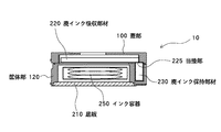
また、インクカートリッジ10の内部には、図3に示すように、廃棄インク開口部125より、インクジェット記録装置の本体からパイプなどの配管系を通じて排出されてくる廃棄インクを保持するための廃インク保持部材230が収納されている。廃インク保持部材230は廃インク吸収部材220と互いに当接部225を介して接しており、前述したインクジェットヘッド410のメンテナンス動作によって生じた廃棄インクは廃インク保持部材230を介して廃インク吸収部材220に吸収される。この廃インク保持部材230は廃インク吸収部材220の端部を折り曲げるなどして、廃インク吸収部材220に一体的に構成しても良い。
【0043】
次に、本実施形態のインク供給システムにおけるインクジェット記録装置に用いられるインクジェットヘッドについて説明する。
【0044】
図6に、インクジェットヘッドを吐出面側からみた斜視図を示す。
【0045】
インクジェットヘッド440は、吐出面432にインクを吐出する吐出口431が形成されており、上述したようにノズルの吐出口431近傍に配置した発熱素子または振動素子(不図示)の熱もしくは振動エネルギーにより、ノズル内の液体が吐出される。
【0046】
ヘッド側ジョイント部441には、インクカートリッジ10のジョイント部140に設けられたジョイント穴145Y、145M、145Cに対応する3本の針状筒436Y、436M、436Cからなる針状筒436が設けられている。これら針状筒436Y、436M、436Cは、インクジェットヘッド440内に形成されている、インクを各色毎に貯蔵するインク貯蔵室に連通しており、上述したように、インク供給時には、インクカートリッジ10内のインク容器250からインクの供給を受けるために各ジョイント穴145にそれぞれ挿入される。
【0047】
また、針状筒436Yと針状筒436Mとの間には、位置決め穴142に対応するガイドピン420が設けられている。ガイドピン420は、円錐形状の先端部420aと、位置決め穴142に対して挿入されることで、針状筒436Y、436M、436Cとジョイント穴145Y、145M、145Cとの位置決めをする位置決め部420bとからなり、その長さは針状筒436Y、436M、436Cよりも長いものとなっている。このため、針状筒436がジョイント穴145に挿入されるのに先立ってガイドピン420が位置決め穴142に挿入されることとなる。
【0048】
また、インクジェットヘッド410には、図1に示すガイドレール438によってインクジェットヘッド410を支持するため、2つの軸受け560が吐出口431およびヘッド側ジョイント部441を挟んで両側に配置されている。
【0049】
次に、本実施形態のインク供給システムにおけるインク供給動作について説明する。
【0050】
本実施形態における、インクカートリッジを使用したインク供給システムは、断続的にインクジェットヘッド410にインクを満たす、いわゆるピットイン方式によりインク供給を行う。
【0051】
すなわち、インクジェットヘッド410のインク貯蔵室内のインクが所定の量まで減ると、インクジェットヘッド410はホームポジションまで戻り、インクジェットヘッド410の針状筒436がジョイント穴145に挿通されて、インクジェットヘッド410に接続したポンプの負圧により所定容量インクがインク容器250内からインクジェットヘッド410のインク貯蔵室内へと供給される。
【0052】
インク供給が終了し、記録を行う際には、インクジェットヘッド410に設けられた針状筒36とジョイント穴145との結合は解除され、インクジェットヘッド410が被記録媒体Pに対して走査されることにより記録がなされる。
【0053】
さらに所定の記録後、再び、インクジェットヘッド410の針状筒436がジョイント穴145に挿通され、インクジェットヘッドに接続したポンプの負圧により所定容量のインクがインク容器内からインクジェットヘッドに供給がなされる。
【0054】
このように本実施形態のインク供給システムは、インクジェットヘッド410の針状筒436をジョイント部140のジョイント穴145へ挿通する動作と、挿通を解除する動作とが繰り返される。
【0055】
次に、上述したインク供給動作における、インクジェットヘッド410の針状筒436の、インクカートリッジ10のジョイント穴145への位置決めおよび挿入に関して説明する。
【0056】
図7はホームポジションに位置するインクジェットヘッドとインクカートリッジとの位置関係を示す斜視図であり、図8(a)〜図8(c)は、インクジェットヘッドの針状筒およびガイドピンがインクカートリッジのジョイント穴および位置決め穴に挿入されていく状態の各工程をジョイント部側からみた図である。
【0057】
インクジェットヘッド410が図7および図8(a)に示すようにホームポジションに位置することで、インクジェットヘッド410の針状筒436およびガイドピン420がインクカートリッジ10のジョイント穴145および位置決め穴142の真上に位置する。
【0058】
図8(a)の状態からインクカートリッジ10が上方に移動を開始し、図8(b)にように、まず、針状筒436Y、436M、436Cよりも長いガイドピン420の先端部420aが位置決め穴142に挿入され始める。この時点では、針状筒436Y、436M、436Cは、ジョイント穴145Y、145M、145Cに挿入されていない。
【0059】
円錐形状の先端部420aによって、位置決め穴142に案内されたガイドピン420は、図8(b)の状態からさらにインクカートリッジ10が上方に移動することで位置決め部420bが位置決め穴142に挿入されることとなり、これにより、ジョイント穴145Y、145M、145Cに対する針状筒436Y、436M、436Cの位置が決まる。
【0060】
位置決め部420bが位置決め穴142に挿入されてジョイント穴145Y、145M、145Cに対する針状筒436Y、436M、436Cの位置が完了した状態からさらにインクカートリッジ10が上方に移動することで、図8(c)に示すように、ジョイント穴145Y、145M、145Cに対して針状筒436Y、436M、436Cが挿入されることとなる。各針状筒436がジョイント穴145に対して所定の量だけ挿入されてから、インク供給が開始される。
【0061】
以上説明したように、本実施形態のインク供給システムにおいては、各針状筒436よりも長さが長いガイドピン420による位置決めがなされてから各針状筒436が各位置決め穴142に挿入される構成であるため、インクジェットヘッド440とインクカートリッジ10とが精度よく連結される。
【0062】
また、位置決め穴142がジョイント穴145Yとジョイント穴145Mとのピッチ間に配置されていることでインクカートリッジ10が大型化することがない。また、これに対応してガイドピン420も針状筒436Yと針状筒436Mとのピッチ間に配置されることでインクジェットヘッド440も大型化することがない。よって、インクジェット記録装置30も大型化することがない。
【0063】
さらに、位置決め穴142がジョイント穴145Yとジョイント穴145Mとのピッチ間に配置されていることで、インクがジョイント部140に付着することがあっても、余剰インクがこの位置決め穴142に入り込むことで特に混色が目立ちやすいイエローと他のインクとの混色を防止することができる。
【0064】
(第2の実施形態)
図9に本実施形態のインクカートリッジの位置決め穴部分の断面図を示す。
【0065】
本実施形態は、位置決め穴142と、廃インク吸収部材220を収納している廃インク吸収部材収納部220aと連通する連通管149が設けられている以外は、第1の実施形態と同様であるため詳細の説明は省略する。
【0066】
本実施形態の場合、連通管149によって位置決め穴142と廃インク吸収部材収納部220aとが連通しているため、インクがジョイント部140に付着し、位置決め穴142に入り込んだ余剰インクが連通管149を通じて廃インク吸収部材220へと排出されることとなる。したがって、長期間のジョイント動作などにおいて、より多くのインクがジョイント部付近に付着する場合においても、これら余剰インクを最終的に連通管149を通じて廃インク吸収部材220へと排出できるため、より確実に混色等の発生を防止することができる。
【0067】
【発明の効果】
以上説明したように本発明によれば、記録ヘッドは各インク受給部のピッチ間に位置決め突起部を有し、また、インクカートリッジも、各インク供給部のピッチ間に位置決め穴が形成されているので記録装置が位置決めのために大型化してしまうことがない。
【0068】
さらには、本発明によれば、インクカートリッジの各インク供給部の間に形成された位置決め穴に余剰インクが入り込むことで、各色の混色を防止することができる。
【図面の簡単な説明】
【図1】 本発明の第1の実施形態のインク供給システムにおけるインクジェット記録装置の内部概要を示す斜視図である。
【図2】 本発明の第1の実施形態のインクカートリッジの外観斜視図である。
【図3】 図2に示すインクカートリッジのA−A線での断面図である。
【図4】 図2に示すインクカートリッジの上面図である。
【図5】 図4に示すインクカートリッジのB−B線での断面図、C−C線での断面図、および図5(b)に示すC部に示す位置決め部材近傍の拡大図である。
【図6】 本発明の第1の実施形態のインクジェットヘッドを吐出面側からみた斜視図である。
【図7】 ホームポジションに位置するインクジェットヘッドとインクカートリッジとの位置関係を示す斜視図である。
【図8】 インクジェットヘッドの針状筒およびガイドピンがインクカートリッジのジョイント穴および位置決め穴に挿入されていく状態の各工程をジョイント部側からみた図である。
【図9】 本発明の第2の実施形態におけるインクカートリッジの位置決め穴部分の断面図である。
【符号の説明】
10 インクカートリッジ
30 インクジェット記録装置
31 給紙カセット
34 インクカートリッジ交換
36 針状筒
100 蓋部
120 筐体部
125 廃棄インク開口部
130 吸収部材
140 ジョイント部
142 位置決め穴
143 押さえ板
145、145Y、145M、145C ジョイント穴
148 位置決め部材
149 連通管
170 溝部
210 底板
220 廃インク吸収部材
220a 廃インク吸収部材収納部
225 当接部
230 廃インク保持部材
250 インク容器
300 シール部材
350 インク連結部材
360 インク容器結合部材
410 インクジェットヘッド
420 ガイドピン
420a 先端部
420b 位置決め部
430 インクカートリッジガイドフレーム
431 吐出口
432 吐出面
436、436Y、436M、436C 針状筒
438 ガイドレール
440 インクジェットヘッド
441 ヘッド側ジョイント部[0001]
BACKGROUND OF THE INVENTION
The present invention relates to an ink supply system.And ink cartridgeIt is about.
[0002]
[Prior art]
Conventionally, a pit-in ink supply method is known as one of methods for supplying ink to a liquid discharge head (inkjet head). The pit-in ink supply system includes a liquid storage container (sub tank) for supplying liquid to the liquid discharge head, and a container (ink cartridge) for replenishing the liquid is installed in the liquid storage container (sub tank). A liquid cartridge provided in a part of the sub-tank in a container (main tank) for replenishing liquid at a predetermined position by mounting a head cartridge on which the inkjet head and the inkjet head are integrally mounted, mounted on the carriage This is a system in which liquid is replenished to the sub tank by connecting to the member.
[0003]
In the case of replenishing ink by this method, a configuration for replenishing a liquid storage container with a predetermined amount of ink without excess or deficiency is required. Therefore, it is necessary to connect a liquid supply member provided in a part of the liquid storage container to a container (ink cartridge) that reliably replenishes the liquid. Further, since the ink filling into the liquid storage container is performed a plurality of times as the ink is consumed, the reliability when the liquid supply member provided in a part of the liquid storage container is connected to the container (ink cartridge) for replenishing the liquid. And durability are important. In order to increase the reliability after the contact, it is necessary to accurately connect the liquid supply member provided in a part of the liquid storage container to a predetermined supply portion of the ink cartridge.
[0004]
For this reason, as a connection method that is commonly used, a recording device is disclosed in which a convex portion for guide is provided on a part of an ink cartridge to lock and position the ink jet recording device (for example, Patent Document 1).
[0005]
Also, the ink supply port surface of the ink cartridge has a claw portion, and the ink jet recording apparatus has a mounting portion so as to engage with this, and the projection of this claw portion prevents erroneous insertion with the main body, A device that also serves as a lid opening / closing latch is disclosed (for example, see Patent Document 2).
Furthermore, there is also disclosed an ink cartridge in which a positioning pin is provided and a corresponding positioning hole is provided on the holder side of the cartridge so as to guarantee the joining accuracy of the ink supply unit by engaging both of them (for example, And Patent Document 3).
[0006]
In addition, the positioning pin and the ink supply pipe are fixedly held at a certain distance, and the positioning receiving portion and the coupling portion of the supply pipe are integrated with each other to slide in a state where they are joined. There is a proposal to perform positioning by displacing the slide part according to the joining, and conversely, the positioning receiving part and the connecting part of the supply pipe are fixed, and the positioning pin and the ink supply pipe are respectively connected to these parts. However, there is disclosed a recording apparatus that has a mechanism that slides in an integrated state, and that performs positioning by displacing a slide portion in accordance with the joining (see, for example, Patent Document 4).
There are proposals.
[0007]
[Patent Document 1]
JP-A-01-141750
[Patent Document 2]
JP 05-261935 A
[Patent Document 3]
JP 2000-127444 A
[Patent Document 4]
Japanese Patent Laid-Open No. 06-8463
[0008]
[Problems to be solved by the invention]
However, the ink cartridge positioning method proposed in the above-described conventional example is a container for replenishing the liquid as described above, on the assumption that the user is usually mounted once or several times. Ink filling is performed by connecting a liquid supply member provided in a part of the sub tank to the (ink cartridge), and the ink filling to the sub tank is performed a plurality of times as the ink is consumed. Depending on the conversion, there may be a case of several tens to several hundred times. Therefore, high positioning reliability and durability in long-term use are required when connecting a liquid supply member provided in a part of the liquid storage container to a container (ink cartridge) for replenishing liquid.
[0009]
On the other hand, in recent ink jet recording apparatuses, the progress of color recording has progressed, and a device that forms a color image by superposing droplets with a plurality of ink jet heads has become widespread. In general, when performing color recording, four types of inkjet heads corresponding to three primary colors of yellow (Y), magenta (M), cyan (C), or four colors including black (B) in these three primary colors; An ink cartridge will be used.
[0010]
In recent years, an ink jet recording apparatus that mounts such 3 to 4 color ink jet heads and forms a full color image has been put into practical use. In addition to the above four colors, two colors of light magenta (LM) and light cyan (LC) are added, and ink-jet recording capable of forming images with high-definition photographic image quality using six colors of ink. The device has also been put into practical use.
[0011]
Accordingly, a plurality of color ink containers are laid out in one ink cartridge, and it is necessary to fill (connect) ink for each of these colors (see, for example, FIG. 4 of Patent Document 3).
[0012]
However, if the claw portions and pins in the conventional example as described above are provided for each of these connection portions, the ink cartridge itself becomes large.
[0013]
Further, in the embodiment disclosed in
[0014]
On the other hand, in order to avoid this increase in size, if an attempt is made to configure the positioning of a plurality of connections with a single claw or pin, it becomes difficult to accurately absorb variations in each connection portion, resulting in a decrease in connection accuracy. . Further, as the positioning accuracy decreases, excess ink may remain in the ink cartridge supply section or the like at the time of connection. The surplus ink is gradually accumulated by repeating the above-described connection operation, spreads to the supply unit, and may cause a phenomenon in which different ink colors are mixed and mixed.
[0015]
When the mixed ink is connected, if the liquid supply member provided in a part of the sub-tank is filled, the color of ink discharged will be different, the image quality will deteriorate, and the recording reliability will be reduced. The sex will not be guaranteed.
[0016]
Therefore, the present invention pays attention not only to the above-described high positioning reliability in the connecting portion and the necessity of durability in long-term use, but also to the problem of color enlargement and color mixing, An object of the present invention is to provide an ink supply system that is inexpensive and can be downsized in the pit-in system, can be downsized, has stable performance, and does not cause ink leakage or color mixing and has high reliability.
[0017]
[Means for Solving the Problems]
In order to achieve the above object, an ink supply system of the present invention includes an ink storage chamber that stores ink therein, and a plurality of ink storage chambers that communicate with the ink storage chamber.Needle tubeAnd a recording apparatus having a recording head for ejecting ink onto a recording medium, and a plurality of units that are detachable from the recording apparatus and that contain ink therein and supply ink to the recording headJoint holeHaving an ink cartridge withThe operation of inserting the needle tube of the recording head into the joint hole of the ink cartridge and the operation of releasing the insertion are repeated, and each needle tubeWhenEach joint holeIn the ink supply system in which the ink is supplied from the ink cartridge to the ink storage chamber of the recording head, the recording headEach needle tubeAt least one positioning protrusion between the pitches of the ink cartridges andEach joint holePositioning holes corresponding to the positioning projections are formed between the pitches of the two, and the positioning projections are engaged with the positioning holes.Needle tubeWhenJoint holeAre positioned.
[0018]
In the ink supply system of the present invention as described above, the recording head has the positioning projections between the ink receiving units, and the positioning holes corresponding to the positioning projections are provided between the ink supply units of the ink cartridge. It has a formed configuration. That is, since the positioning protrusions are provided between the pitches of the ink receiving portions, the recording head is not increased in size by the positioning member. Also, the ink cartridge is not increased in size because the positioning holes are formed between the pitches of the ink supply portions. Therefore, the ink supply system of the present invention can perform positioning without enlarging the recording apparatus. Furthermore, since a positioning hole is formed between the ink supply portions of the ink cartridge, even when a plurality of colors of ink are supplied, excess ink at the time of supply enters the positioning hole, Color mixing of each color can be prevented.
Further, the ink supply system of the present invention includes the plurality ofJoint holeCorresponds to at least yellow ink, magenta ink, and cyan ink, and the positioning hole corresponds to yellow ink.Joint holeAnd other inksJoint holeIt may be arranged between.
An ink cartridge according to the present invention includes an ink storage chamber that stores ink therein, and a plurality of ink cartridges that communicate with the ink storage chamber.Needle tubeA plurality of the ink cartridges that can be attached to and detached from the recording head.Needle tubeA plurality of inks for supplying ink to the recording headJoint holeAnd positioning holes corresponding to positioning protrusions disposed on the recording head, and the plurality of the positioning holesJoint holeAnd the positioning holes are arranged in a straight line, and the positioning holes are the plurality of the positioning holes.Joint holeIt is characterized by being arranged between the pitches.
In addition, the ink cartridge of the present invention includes the plurality of the ink cartridges.Joint holeCorresponds to at least yellow ink, magenta ink, and cyan ink, and the positioning hole corresponds to yellow ink.Joint holeAnd other inksJoint holeIt may be arranged between.
In addition, the ink cartridge of the present invention may have an ink absorbing member inside, and the ink absorbing member and the positioning hole may communicate with each other.
[0019]
DETAILED DESCRIPTION OF THE INVENTION
Next, embodiments of the present invention will be described with reference to the drawings.
[0020]
(First embodiment)
FIG. 1 is a perspective view showing an internal outline of an ink jet recording apparatus in the ink supply system of the present embodiment.
[0021]
The ink
[0022]
The recording medium P supplied into the recording apparatus main body is supported by two guide rails 438 arranged in a direction crossing the conveying direction, and a desired image is formed by ink ejected from the inkjet head 410 that reciprocates. To be recorded. Ink is ejected from the inkjet head 410 by pushing out the liquid in the nozzle by the heat or vibration energy of a heating element or vibration element (not shown) arranged near the nozzle outlet 431 (see FIG. 6). .
[0023]
Further, in the ink
[0024]
Next, the ink cartridge used in the ink jet recording apparatus in the ink supply system of this embodiment will be described in detail.
[0025]
2 is an external perspective view of the ink cartridge, FIG. 3 is a sectional view taken along line AA shown in FIG. 2, FIG. 4 is a top view of the ink cartridge, and FIG. FIG. 5B is a cross-sectional view taken along the line C-C shown in FIG. 4, and FIG. 5C is an enlarged view of the vicinity of the positioning member shown at C in FIG. 5B. Respectively.
[0026]
As shown in FIG. 2 and FIG. 3, the
[0027]
Further, the
[0028]
As shown in FIG. 4, the
[0029]
The
[0030]
The
[0031]
In the present embodiment, an example in which only one
[0032]
Further, in the present embodiment, an example is shown in which these holes are arranged in a straight line, but the present invention is not limited to this, and positioning holes are arranged in parallel to the row of joint holes. There may be.
[0033]
That is, in the present embodiment, the positioning holes are not provided outside the pitch of the joint holes, but any layout may be used as long as the layout is arranged between the joint holes. By doing so, the guide pin is also disposed between the needle-like cylinders, so that the ink cartridge and the recording head can be positioned with high accuracy without increasing the size of the ink cartridge and the recording head. It can be carried out.
[0034]
Even if the ink may adhere to the joint part of the ink cartridge due to the joint operation, since the positioning hole is located between the joint holes, the surplus ink attached to the joint part enters the hole, and each ink Color mixing by color can be prevented. In the present embodiment, the
[0035]
As shown in FIG. 5A, a seal member 300 is incorporated in the
[0036]
An elbow-type
[0037]
The
[0038]
As shown in FIG. 5B, the
[0039]
As shown in FIG. 5A and FIG. 5B, the absorbing
[0040]
In addition, an
[0041]
A waste
[0042]
Further, as shown in FIG. 3, the
[0043]
Next, an ink jet head used in the ink jet recording apparatus in the ink supply system of this embodiment will be described.
[0044]
FIG. 6 is a perspective view of the ink jet head as seen from the ejection surface side.
[0045]
The
[0046]
The head-side joint portion 441 is provided with a needle-like tube 436 including three needle-
[0047]
Further, a
[0048]
In addition, in order to support the inkjet head 410 by the guide rail 438 shown in FIG. 1, the two bearings 560 are arranged on both sides of the ejection port 431 and the head side joint portion 441.
[0049]
Next, an ink supply operation in the ink supply system of this embodiment will be described.
[0050]
In the present embodiment, the ink supply system using the ink cartridge supplies ink by a so-called pit-in method that intermittently fills the inkjet head 410 with ink.
[0051]
That is, when the ink in the ink storage chamber of the inkjet head 410 decreases to a predetermined amount, the inkjet head 410 returns to the home position, and the needle-like cylinder 436 of the inkjet head 410 is inserted into the
[0052]
When the ink supply is completed and recording is performed, the connection between the needle-shaped cylinder 36 provided in the inkjet head 410 and the
[0053]
Further, after a predetermined recording, the needle-like cylinder 436 of the inkjet head 410 is again inserted into the
[0054]
As described above, in the ink supply system of the present embodiment, the operation of inserting the needle-like tube 436 of the inkjet head 410 into the
[0055]
Next, the positioning and insertion of the needle-like cylinder 436 of the inkjet head 410 into the
[0056]
FIG. 7 is a perspective view showing the positional relationship between the ink jet head positioned at the home position and the ink cartridge. FIGS. 8A to 8C show the needle cylinder and guide pin of the ink jet head of the ink cartridge. It is the figure which looked at each process of the state inserted in a joint hole and a positioning hole from the joint part side.
[0057]
When the inkjet head 410 is positioned at the home position as shown in FIGS. 7 and 8A, the needle-like cylinder 436 and the
[0058]
The
[0059]
The
[0060]
When the
[0061]
As described above, in the ink supply system of the present embodiment, each needle-like cylinder 436 is inserted into each
[0062]
Further, the positioning of the
[0063]
Furthermore, since the positioning holes 142 are arranged between the
[0064]
(Second Embodiment)
FIG. 9 shows a cross-sectional view of the positioning hole portion of the ink cartridge of this embodiment.
[0065]
This embodiment is the same as the first embodiment except that a
[0066]
In the case of this embodiment, since the
[0067]
【The invention's effect】
As described above, according to the present invention, the recording head has the positioning protrusions between the pitches of the ink receiving portions, and the ink cartridge has the positioning holes between the pitches of the ink supply portions. Therefore, the recording apparatus is not enlarged for positioning.
[0068]
Furthermore, according to the present invention, it is possible to prevent color mixing of each color by surplus ink entering the positioning holes formed between the ink supply portions of the ink cartridge.
[Brief description of the drawings]
FIG. 1 is a perspective view showing an internal outline of an ink jet recording apparatus in an ink supply system according to a first embodiment of the present invention.
FIG. 2 is an external perspective view of the ink cartridge according to the first embodiment of the present invention.
3 is a cross-sectional view taken along line AA of the ink cartridge shown in FIG.
4 is a top view of the ink cartridge shown in FIG. 2. FIG.
5 is a cross-sectional view taken along line BB, a cross-sectional view taken along line CC in the ink cartridge shown in FIG. 4, and an enlarged view of the vicinity of the positioning member shown in part C shown in FIG. 5B.
FIG. 6 is a perspective view of the ink jet head according to the first embodiment of the present invention as viewed from the ejection surface side.
FIG. 7 is a perspective view showing a positional relationship between an ink jet head positioned at a home position and an ink cartridge.
FIG. 8 is a diagram of each process in a state where the needle-like cylinder and the guide pin of the ink jet head are inserted into the joint hole and the positioning hole of the ink cartridge as viewed from the joint part side.
FIG. 9 is a cross-sectional view of a positioning hole portion of an ink cartridge according to a second embodiment of the present invention.
[Explanation of symbols]
10 Ink cartridge
30 Inkjet recording device
31 Paper cassette
34 Ink cartridge replacement
36 needle tube
100 lid
120 Case
125 Waste ink opening
130 Absorbing member
140 Joint
142 Positioning hole
143 holding plate
145, 145Y, 145M, 145C Joint hole
148 Positioning member
149 Communication pipe
170 Groove
210 Bottom plate
220 Waste ink absorbing member
220a Waste ink absorbing member storage
225 Contact part
230 Waste ink holding member
250 ink container
300 Seal member
350 Ink connecting member
360 Ink container coupling member
410 Inkjet head
420 Guide pin
420a Tip
420b Positioning part
430 Ink cartridge guide frame
431 outlet
432 Discharge surface
436, 436Y, 436M, 436C needle tube
438 guide rail
440 Inkjet head
441 Head side joint
Claims (5)
前記記録ヘッドが前記各針状筒のピッチ間に少なくとも1つの位置決め突起部を有するとともに、前記インクカートリッジの前記各ジョイント穴のピッチ間に前記位置決め突起部に対応した位置決め穴が形成されており、前記位置決め突起部が前記位置決め穴に係合されることで前記針状筒と前記ジョイント穴とが位置決めされることを特徴とするインク供給システム。A recording apparatus having an ink storage chamber for storing ink therein and a plurality of needle-shaped cylinders communicating with the ink storage chamber, the recording apparatus having a recording head that discharges ink to a recording medium, and a removable recording apparatus An ink cartridge having a plurality of joint holes for storing ink therein and supplying ink to the recording head is provided, and a needle-like tube of the recording head is inserted into the joint hole of the ink cartridge. The operation and the operation of releasing the insertion are repeated, and the ink is supplied from the ink cartridge to the ink storage chamber of the recording head by connecting the needle-shaped cylinders and the joint holes. In the ink supply system,
The recording head has at least one positioning projection between the pitches of the needle-shaped cylinders , and positioning holes corresponding to the positioning projections are formed between the pitches of the joint holes of the ink cartridge. The ink supply system is characterized in that the needle-shaped cylinder and the joint hole are positioned by engaging the positioning protrusion with the positioning hole.
前記複数の針状筒に対応した前記記録ヘッドにインクを供給するための複数のジョイント穴と、
前記記録ヘッドに配される位置決め突起部に対応した位置決め穴と、を有し、
前記複数のジョイント穴と前記位置決め穴とは直線状に配され、前記位置決め穴は前記複数のジョイント穴のピッチ間に配されることを特徴とするインクカートリッジ。In an ink cartridge detachably attached to a recording head comprising an ink storage chamber for storing ink therein and a plurality of needle-shaped cylinders communicating with the ink storage chamber
A plurality of joint holes for supplying ink to the recording head corresponding to the plurality of needle-shaped cylinders ;
A positioning hole corresponding to a positioning protrusion disposed on the recording head,
The ink cartridge, wherein the plurality of joint holes and the positioning holes are arranged in a straight line, and the positioning holes are arranged between the pitches of the plurality of joint holes .
Priority Applications (2)
| Application Number | Priority Date | Filing Date | Title |
|---|---|---|---|
| JP2003122008A JP4047216B2 (en) | 2003-04-25 | 2003-04-25 | Ink supply system and ink cartridge |
| US10/806,654 US7114800B2 (en) | 2003-04-25 | 2004-03-22 | Ink supply system and ink cartridge |
Applications Claiming Priority (1)
| Application Number | Priority Date | Filing Date | Title |
|---|---|---|---|
| JP2003122008A JP4047216B2 (en) | 2003-04-25 | 2003-04-25 | Ink supply system and ink cartridge |
Publications (3)
| Publication Number | Publication Date |
|---|---|
| JP2004322531A JP2004322531A (en) | 2004-11-18 |
| JP2004322531A5 JP2004322531A5 (en) | 2005-08-04 |
| JP4047216B2 true JP4047216B2 (en) | 2008-02-13 |
Family
ID=33296583
Family Applications (1)
| Application Number | Title | Priority Date | Filing Date |
|---|---|---|---|
| JP2003122008A Expired - Fee Related JP4047216B2 (en) | 2003-04-25 | 2003-04-25 | Ink supply system and ink cartridge |
Country Status (2)
| Country | Link |
|---|---|
| US (1) | US7114800B2 (en) |
| JP (1) | JP4047216B2 (en) |
Families Citing this family (3)
| Publication number | Priority date | Publication date | Assignee | Title |
|---|---|---|---|---|
| JP2004338383A (en) * | 2003-04-25 | 2004-12-02 | Canon Inc | Ink cartridge, printing device equipped with ink cartridge, and manufacturing process of ink tank |
| JP2007152733A (en) * | 2005-12-05 | 2007-06-21 | Canon Inc | Inkjet recording apparatus and ink tank therefor |
| US10994547B2 (en) | 2015-09-04 | 2021-05-04 | Hewlett-Packard Development Company, L.P. | Housing for a carriage assembly |
Family Cites Families (12)
| Publication number | Priority date | Publication date | Assignee | Title |
|---|---|---|---|---|
| US104949A (en) * | 1870-07-05 | Improvement in let-off mechanism for looms | ||
| JP2639947B2 (en) | 1987-11-30 | 1997-08-13 | キヤノン株式会社 | Ink cartridge holding device |
| GB2242867B (en) * | 1990-02-15 | 1994-04-13 | Canon Kk | Waste ink receiving cartridge and ink recording apparatus using said cartridge |
| JP2877578B2 (en) * | 1990-09-22 | 1999-03-31 | キヤノン株式会社 | Ink jet recording apparatus and ink cartridge mountable on the recording apparatus |
| EP0860285B1 (en) * | 1991-12-11 | 2002-03-06 | Canon Kabushiki Kaisha | Ink jet cartridge |
| JP3110872B2 (en) * | 1992-06-24 | 2000-11-20 | キヤノン株式会社 | Ink jet recording device |
| CA2156809C (en) * | 1994-08-24 | 2003-11-11 | Hiroyuki Inoue | Ink container for ink jet printer, holder for the container carriage for the holder and ink jet printer |
| JPH09267487A (en) * | 1996-04-03 | 1997-10-14 | Canon Inc | Ink tank for recording head, recording head cartridge, and recorder using the recording head |
| JP3295339B2 (en) * | 1996-08-30 | 2002-06-24 | キヤノン株式会社 | Ink tank, holder, inkjet cartridge and cap |
| US6454400B1 (en) * | 1998-09-01 | 2002-09-24 | Canon Kabushiki Kaisha | Liquid container, cartridge including liquid container, printing apparatus using cartridge and liquid discharge printing apparatus |
| US6929356B2 (en) * | 2001-03-21 | 2005-08-16 | Canon Kabushiki Kaisha | Container of consumable supplies for a printer and printer utilizing the container |
| CA2379725C (en) * | 2001-04-03 | 2007-06-12 | Seiko Epson Corporation | Ink cartridge |
-
2003
- 2003-04-25 JP JP2003122008A patent/JP4047216B2/en not_active Expired - Fee Related
-
2004
- 2004-03-22 US US10/806,654 patent/US7114800B2/en not_active Expired - Fee Related
Also Published As
| Publication number | Publication date |
|---|---|
| US7114800B2 (en) | 2006-10-03 |
| US20040212664A1 (en) | 2004-10-28 |
| JP2004322531A (en) | 2004-11-18 |
Similar Documents
| Publication | Publication Date | Title |
|---|---|---|
| JP5552931B2 (en) | Liquid container and liquid ejection system | |
| KR100233977B1 (en) | Ink recharger for inkjet print cartridge having sliding valve connectable to print cartridge | |
| JP3658373B2 (en) | Liquid storage container, ink jet cartridge, and ink jet recording apparatus | |
| KR100240540B1 (en) | Syringe for filling print cartridge and establishing correct back pressure | |
| KR100235282B1 (en) | Inkjet print cartridge having handle which incorporates an ink fill port | |
| AU768376B2 (en) | Ink tank, ink-jet cartridge, ink-supplying apparatus, ink-jet printing apparatus and method for supplying ink | |
| US7134747B2 (en) | Ink container, recording head and recording device using same | |
| KR100235281B1 (en) | Inkjet print cartridge having two ink inlet ports for initial filling and recharging | |
| NZ280044A (en) | Multi-chambered ink cartridge for ink jet printer | |
| KR100266931B1 (en) | Inkjet print cartridge having valve connectable to an external ink reservoir for recharging the print cartridge | |
| KR100235283B1 (en) | Inkjet print cartridge having a first inlet port for initial filling and a second inlet port for ink replenishment without removing the print cartridge from the printer | |
| TWI239299B (en) | Ink cartridge, recording apparatus employing ink cartridge, and manufacturing method for ink cartridge | |
| JP4382170B2 (en) | Ink supply station in ink jet printer, ink supply container used in the station, and replenishment ink supply method | |
| JP2003072100A (en) | Ink cartridge incorporating ink bag and its filling method | |
| JP2023115276A (en) | Inkjet recording device and ink tank | |
| JPH10235893A6 (en) | Ink supply station in ink jet printer, ink supply container used in the station, and replenishment ink supply method | |
| JP2007313829A (en) | Inkjet recording apparatus and ink recovery method | |
| US7101027B2 (en) | Inkjet printer | |
| JP4047216B2 (en) | Ink supply system and ink cartridge | |
| JP2005329709A (en) | Ink vessel, inkjet recording head, and inkjet recording apparatus | |
| JP2000334977A (en) | Ink tank and recorder | |
| JPH08323989A (en) | Ink cartridge, ink-jet recording device equipped with more than one said ink cartridge | |
| GB2315461A (en) | Multi-colour ink cartridge having an enlarged supply port | |
| JP2011131514A (en) | Liquid supply device | |
| JP3209992B2 (en) | Ink supply container and inkjet recording head |
Legal Events
| Date | Code | Title | Description |
|---|---|---|---|
| A521 | Request for written amendment filed |
Free format text: JAPANESE INTERMEDIATE CODE: A523 Effective date: 20041224 |
|
| A621 | Written request for application examination |
Free format text: JAPANESE INTERMEDIATE CODE: A621 Effective date: 20041224 |
|
| A977 | Report on retrieval |
Free format text: JAPANESE INTERMEDIATE CODE: A971007 Effective date: 20060601 |
|
| A131 | Notification of reasons for refusal |
Free format text: JAPANESE INTERMEDIATE CODE: A131 Effective date: 20060621 |
|
| A521 | Request for written amendment filed |
Free format text: JAPANESE INTERMEDIATE CODE: A523 Effective date: 20060811 |
|
| TRDD | Decision of grant or rejection written | ||
| A01 | Written decision to grant a patent or to grant a registration (utility model) |
Free format text: JAPANESE INTERMEDIATE CODE: A01 Effective date: 20071107 |
|
| A61 | First payment of annual fees (during grant procedure) |
Free format text: JAPANESE INTERMEDIATE CODE: A61 Effective date: 20071121 |
|
| FPAY | Renewal fee payment (event date is renewal date of database) |
Free format text: PAYMENT UNTIL: 20101130 Year of fee payment: 3 |
|
| R150 | Certificate of patent or registration of utility model |
Free format text: JAPANESE INTERMEDIATE CODE: R150 |
|
| FPAY | Renewal fee payment (event date is renewal date of database) |
Free format text: PAYMENT UNTIL: 20101130 Year of fee payment: 3 |
|
| FPAY | Renewal fee payment (event date is renewal date of database) |
Free format text: PAYMENT UNTIL: 20111130 Year of fee payment: 4 |
|
| FPAY | Renewal fee payment (event date is renewal date of database) |
Free format text: PAYMENT UNTIL: 20121130 Year of fee payment: 5 |
|
| FPAY | Renewal fee payment (event date is renewal date of database) |
Free format text: PAYMENT UNTIL: 20131130 Year of fee payment: 6 |
|
| LAPS | Cancellation because of no payment of annual fees |