JP4046893B2 - Database copying apparatus, database copying method, and computer-readable recording medium recording a database copying program - Google Patents
Database copying apparatus, database copying method, and computer-readable recording medium recording a database copying program Download PDFInfo
- Publication number
- JP4046893B2 JP4046893B2 JP14923199A JP14923199A JP4046893B2 JP 4046893 B2 JP4046893 B2 JP 4046893B2 JP 14923199 A JP14923199 A JP 14923199A JP 14923199 A JP14923199 A JP 14923199A JP 4046893 B2 JP4046893 B2 JP 4046893B2
- Authority
- JP
- Japan
- Prior art keywords
- database
- data
- records
- update
- copying
- Prior art date
- Legal status (The legal status is an assumption and is not a legal conclusion. Google has not performed a legal analysis and makes no representation as to the accuracy of the status listed.)
- Expired - Fee Related
Links
Images


Classifications
-
- G—PHYSICS
- G06—COMPUTING OR CALCULATING; COUNTING
- G06F—ELECTRIC DIGITAL DATA PROCESSING
- G06F16/00—Information retrieval; Database structures therefor; File system structures therefor
- G06F16/20—Information retrieval; Database structures therefor; File system structures therefor of structured data, e.g. relational data
- G06F16/27—Replication, distribution or synchronisation of data between databases or within a distributed database system; Distributed database system architectures therefor
-
- G—PHYSICS
- G06—COMPUTING OR CALCULATING; COUNTING
- G06F—ELECTRIC DIGITAL DATA PROCESSING
- G06F11/00—Error detection; Error correction; Monitoring
- G06F11/07—Responding to the occurrence of a fault, e.g. fault tolerance
- G06F11/14—Error detection or correction of the data by redundancy in operations
- G06F11/1402—Saving, restoring, recovering or retrying
- G06F11/1415—Saving, restoring, recovering or retrying at system level
- G06F11/1441—Resetting or repowering
-
- Y—GENERAL TAGGING OF NEW TECHNOLOGICAL DEVELOPMENTS; GENERAL TAGGING OF CROSS-SECTIONAL TECHNOLOGIES SPANNING OVER SEVERAL SECTIONS OF THE IPC; TECHNICAL SUBJECTS COVERED BY FORMER USPC CROSS-REFERENCE ART COLLECTIONS [XRACs] AND DIGESTS
- Y10—TECHNICAL SUBJECTS COVERED BY FORMER USPC
- Y10S—TECHNICAL SUBJECTS COVERED BY FORMER USPC CROSS-REFERENCE ART COLLECTIONS [XRACs] AND DIGESTS
- Y10S707/00—Data processing: database and file management or data structures
- Y10S707/953—Organization of data
- Y10S707/954—Relational
-
- Y—GENERAL TAGGING OF NEW TECHNOLOGICAL DEVELOPMENTS; GENERAL TAGGING OF CROSS-SECTIONAL TECHNOLOGIES SPANNING OVER SEVERAL SECTIONS OF THE IPC; TECHNICAL SUBJECTS COVERED BY FORMER USPC CROSS-REFERENCE ART COLLECTIONS [XRACs] AND DIGESTS
- Y10—TECHNICAL SUBJECTS COVERED BY FORMER USPC
- Y10S—TECHNICAL SUBJECTS COVERED BY FORMER USPC CROSS-REFERENCE ART COLLECTIONS [XRACs] AND DIGESTS
- Y10S707/00—Data processing: database and file management or data structures
- Y10S707/964—Database arrangement
- Y10S707/966—Distributed
- Y10S707/967—Peer-to-peer
- Y10S707/968—Partitioning
-
- Y—GENERAL TAGGING OF NEW TECHNOLOGICAL DEVELOPMENTS; GENERAL TAGGING OF CROSS-SECTIONAL TECHNOLOGIES SPANNING OVER SEVERAL SECTIONS OF THE IPC; TECHNICAL SUBJECTS COVERED BY FORMER USPC CROSS-REFERENCE ART COLLECTIONS [XRACs] AND DIGESTS
- Y10—TECHNICAL SUBJECTS COVERED BY FORMER USPC
- Y10S—TECHNICAL SUBJECTS COVERED BY FORMER USPC CROSS-REFERENCE ART COLLECTIONS [XRACs] AND DIGESTS
- Y10S707/00—Data processing: database and file management or data structures
- Y10S707/99931—Database or file accessing
- Y10S707/99933—Query processing, i.e. searching
-
- Y—GENERAL TAGGING OF NEW TECHNOLOGICAL DEVELOPMENTS; GENERAL TAGGING OF CROSS-SECTIONAL TECHNOLOGIES SPANNING OVER SEVERAL SECTIONS OF THE IPC; TECHNICAL SUBJECTS COVERED BY FORMER USPC CROSS-REFERENCE ART COLLECTIONS [XRACs] AND DIGESTS
- Y10—TECHNICAL SUBJECTS COVERED BY FORMER USPC
- Y10S—TECHNICAL SUBJECTS COVERED BY FORMER USPC CROSS-REFERENCE ART COLLECTIONS [XRACs] AND DIGESTS
- Y10S707/00—Data processing: database and file management or data structures
- Y10S707/99951—File or database maintenance
- Y10S707/99952—Coherency, e.g. same view to multiple users
- Y10S707/99953—Recoverability
Landscapes
- Engineering & Computer Science (AREA)
- Databases & Information Systems (AREA)
- Theoretical Computer Science (AREA)
- Computing Systems (AREA)
- Data Mining & Analysis (AREA)
- Physics & Mathematics (AREA)
- General Engineering & Computer Science (AREA)
- General Physics & Mathematics (AREA)
- Information Retrieval, Db Structures And Fs Structures Therefor (AREA)
Abstract
Description
【0001】
【発明の属する技術分野】
本発明は、データベースの複写技術に関し、特に、汎用性を高める技術に関する。
【0002】
【従来の技術】
近年では、業務の国際化や24時間サービスにより、業務プログラムを実行するコンピュータシステムを無停止で運用する必要性が高まっている。
【0003】
ところで、コンピュータシステムでは、ハードウエア等の保守のために、システムを停止させる必要がある。コンピュータシステムの無停止運用では、システムを停止できないため、保守を行うことができない。このため、コンピュータシステムを2セット用意し、交互に運用を切り替えることにより、一方のシステムを停止させて保守を行う運用形態が考えられる。
【0004】
しかしながら、保守作業には、ディスク装置の保守も含まれるため、2つのコンピュータシステム間で同一ディスク装置を共用することはできない。従って、システム毎に別のディスク装置とする必要があり、運用の切り替え時に、データベース(以下「DB」という)の複写が必要となる。DBの複写は、コンピュータシステムの利用者に対するサービスが停止しない程度に、充分速くなければならない。
【0005】
このような課題を解決するために、本出願人は、更新系データベースの複写方式(特開平10−207754号公報参照)を提案した。この技術は、業務プログラムが抽出済みデータに対してDBを更新した場合にだけ、更新差分を取得,反映してDBの等価性を保証するものである。そして、データ抽出時には、抽出対象範囲を排他占有し、その範囲内のレコード及びレコード間の接続関係(以下「セット関係」という)を一気に抽出する。
【0006】
【発明が解決しようとする課題】
しかしながら、DB構造によっては、セット関係がDB全体に及ぶ可能性があり、次のような不具合が発生するおそれがある。即ち、セット関係がDB全体に及ぶ場合には、DB全体を排他占有してデータを抽出することとなり、実質的にDB更新が不可能となってしまう。従って、従来技術では、DBの複写に関してDB構造上の制約があり、汎用性が低いものであった。
【0007】
そこで、本発明は以上のような従来の問題点に鑑み、DB構造の如何にかかわらずDB複写を効率的に行えるようにし、汎用性を高めたデータベース複写技術を提供することを目的とする。
【0008】
【課題を解決するための手段】
このため、請求項1記載の発明は、複写元データベースを所定領域に分割し、各領域に含まれるレコード及び該レコード間の接続関係を複写先データベースに複写するデータ複写手段と、前記複写元データベースから、異なった領域に夫々含まれるレコード間の接続関係を抽出する接続関係抽出手段と、該接続関係抽出手段により抽出された接続関係に基づいて、前記データ複写手段により複写先データベースに複写されたレコード間の接続関係を再現する接続関係再現手段と、を含んでデータベース複写装置を構成したことを特徴とする。
【0009】
かかる構成によれば、データベースの複写は、次のようにして行われる。
(1)複写元データベースが所定領域に分割され、各領域に含まれるレコード及びレコード間の接続関係が複写先データベースに複写される。
【0010】
(2)複写元データベースから、異なった領域に夫々含まれるレコード間の接続関係が抽出される。
(3)抽出された接続関係に基づいて、複写先データベースに複写されたレコード間の接続関係が再現される。
【0011】
従って、レコード間の接続関係がデータベース全体に及ぶ場合であっても、分割された領域単位でのデータベース複写が行われ、その後、異なる領域に夫々含まれるレコード間の接続関係が再現される。このため、従来技術のように、広範囲に亘るデータベースの排他占有が不要となり、例えば、オンラインシステムの稼動中にデータベース複写を行うことが可能となる。
【0012】
請求項2記載の発明は、前記データ複写手段によりレコード及び該レコード間の接続関係が複写された複写元データベースの領域に対してデータベース更新要求があったときに、該データベース更新要求による更新差分を取得する更新差分取得手段と、該更新差分取得手段により取得された更新差分に基づいて、前記データ複写手段により複写先データベースに複写されたレコード及び該レコード間の接続関係を更新するデータ更新手段と、当該更新差分取得手段により取得された更新差分に基づいて、前記接続関係抽出手段により抽出された接続関係を更新する接続関係更新手段と、を含んだ構成であることを特徴とする。
【0013】
かかる構成によれば、レコード及びレコード間の接続関係が複写された複写元データベースの領域に対してデータベース更新要求があったときには、データベース更新要求による更新差分が取得される。即ち、複写元データベースにおけるレコード等が複写済みである領域に対して更新を行っても、その更新が複写先データベースに反映されないことから、更新差分が取得されるのである。そして、取得された更新差分に基づいて、複写先データベースに複写されたレコード及びレコード間の接続関係、並びに、異なる領域に夫々含まれるレコード間の接続関係が更新される。その後、更新された異なる領域に含まれるレコード間の接続関係に基づいて、複写先データベースに複写されたレコード間の接続関係が再現される。
【0014】
請求項3記載の発明は、前記データ複写手段及び前記接続関係抽出手段による複写元データベースに対する処理が完了したか否かを判定する処理完了判定手段と、前記データ複写手段によりレコード及び該レコード間の接続関係が複写された複写元データベースの領域に対してデータベース更新要求があったときに、該データベース更新要求による更新差分を取得する更新差分取得手段と、を備え、前記接続関係再現手段は、前記処理完了判定手段により複写元データベースに対する処理が完了したと判定されたときに、前記接続関係抽出手段により抽出された接続関係及び前記更新差分取得手段により取得された更新差分に基づいて、前記データ複写手段により複写先データベースに複写されたレコード間の接続関係を再現及び更新する構成であることを特徴とする。
【0015】
かかる構成によれば、レコード及びレコード間の接続関係が複写された複写元データベースの領域に対してデータベース更新要求があったときには、データベース更新要求による更新差分が取得される。そして、複写元データベースに対する処理が完了すると、接続関係及び更新差分に基づいて、複写先データベースに複写されたレコード間の接続関係が再現及び更新される。従って、請求項2記載の発明のような抽出された接続関係の更新処理が不要となる。
【0016】
請求項4記載の発明は、前記接続関係抽出手段により抽出された接続関係は、不揮発性記憶媒体上に保持される構成であることを特徴とする。
ここで、「不揮発性記憶媒体」とは、例えば、ハードディスク装置のように、電源が遮断されたときであってもその内容が保持される記憶媒体をいう。
【0017】
かかる構成によれば、接続関係抽出手段により抽出された接続関係が大きくなっても、コンピュータシステムのメモリ消費が抑制される。また、データベースの複写中にコンピュータシステムがダウンしても、接続関係が保持されているので,再起動時にデータベースの回復が可能となる。
【0018】
請求項5記載の発明は、複写元データベースを所定領域に分割し、各領域に含まれるレコード及び該レコード間の接続関係を複写先データベースに複写するデータ複写工程と、前記複写元データベースから、異なった領域に夫々含まれるレコード間の接続関係を抽出する接続関係抽出工程と、該接続関係抽出工程により抽出された接続関係に基づいて、前記データ複写工程により複写先データベースに複写されたレコード間の接続関係を再現する接続関係再現工程と、を含んでデータベース複写方法を構成したことを特徴とする。
【0019】
かかる構成によれば、データベースの複写は、次のようにして行われる。
(1)複写元データベースが所定領域に分割され、各領域に含まれるレコード及びレコード間の接続関係が複写先データベースに複写される。
【0020】
(2)複写元データベースから、異なった領域に夫々含まれるレコード間の接続関係が抽出される。
(3)抽出された接続関係に基づいて、複写先データベースに複写されたレコード間の接続関係が再現される。
【0021】
従って、レコード間の接続関係がデータベース全体に及ぶ場合であっても、分割された領域単位でのデータベース複写が行われ、その後、異なる領域に夫々含まれるレコード間の接続関係が再現される。このため、従来技術のように、広範囲に亘るデータベースの排他占有が不要となり、例えば、オンラインシステムの稼動中にデータベース複写を行うことが可能となる。
【0022】
請求項6記載の発明は、複写元データベースを所定領域に分割し、各領域に含まれるレコード及び該レコード間の接続関係を複写先データベースに複写するデータ複写機能と、前記複写元データベースから、異なった領域に夫々含まれるレコード間の接続関係を抽出する接続関係抽出機能と、該接続関係抽出機能により抽出された接続関係に基づいて、前記データ複写機能により複写先データベースに複写されたレコード間の接続関係を再現する接続関係再現機能と、を実現するためのデータベース複写プログラムを記録媒体に記録したことを特徴とする。
【0023】
ここで、「記録媒体」とは、各種情報を確実に記録でき、かつ、必要に応じて確実に取り出し可能なものをいい、磁気テープ,磁気ディスク,磁気ドラム,ICカード,CD−ROM等の可搬記録媒体が該当する。
【0024】
かかる構成によれば、データ複写機能と、接続関係抽出機能と、接続関係再現機能と、を実現するためのデータベース複写プログラムが記録媒体に記録される。従って、かかるプログラムを記録した記録媒体があれば、一般的なコンピュータシステムを利用して、本発明に係るデータベース複写装置を容易に構築することが可能となる。
【0025】
【発明の実施の形態】
以下、添付された図面を参照して本発明を詳述する。
本発明を詳述する前に、従来技術の問題点を再度説明する。
【0026】
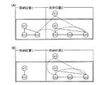
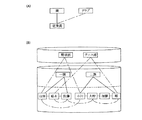
図20は、オンラインシステムの運用形態の一例を示す。従来の運用例では、図20(A)に示すように、オンラインサービスの停止時間内(図では、22時〜翌日7時)に、保守等のシステム停止を前提とした作業が行われていた。しかし、24時間サービス等によりオンラインシステムを無停止で運用するようになると、1つのコンピュータシステムでは、図20(B)に示すように、システム停止を前提とした作業ができなくなってしまう。このため、図20(C)に示すように、2つのコンピュータシステムを用いて、システムを交互に運用を切り替えることにより、システム停止を前提とした作業が可能になる。
【0027】
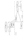
2つのコンピュータシステムを交互に切り替えるためには、前述したように、DBの複写が必要となる。DBの複写処理について、図21を参照しつつ説明すると、次のようになる。なお、DB複写は、システム1のDBからシステム2のDBへ行うものとする。
【0028】
(1)システム切り替えに先立って、システム1のDBからデータを抽出する。
(2)DB抽出と連動して、システム1に対するサービス要求の更新差分の取得を開始する。
【0029】
(3)抽出したデータを、システム2のDBに複写する。
(4)システム1のサービスを停止する。この時点まで、システム1ではサービスを行っており、更新差分が取得される。
【0030】
(5)更新差分を反映して、システム1のDBとシステム2のDBとを等価にする。この場合、DB抽出後の更新分を反映するだけであるので、処理は短時間で終了し、オンラインシステムの停止は利用者に分からない程度になる。
【0031】
(6)システム1とシステム2とのDBが等価状態になったので、システム2のDBを使用してサービスを再開する。
以上説明した従来技術によるDB複写では、データ抽出範囲を排他占有し、その範囲内のデータ及びセット関係を一気に抽出するため、セット関係がDB全体に及ぶ場合には、短時間でのDB更新が不可能となってしまう。即ち、図22に示すような「n:1型」のDBの場合であって、図23に示すようなデータ格納構造である場合には、異なった格納位置に跨ったセット関係があるため、DB全体を排他占有しなければならない。オンラインシステム等におけるDBは、一般的に大規模であるため、DB全体を排他占有した場合には、短時間でのDB複写は到底望めないこととなる。従って、コンピュータシステムを短時間で切り替えることは不可能となる。
【0032】
次に、このような従来技術の問題点を解決するための方法について説明する。
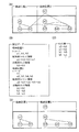
図1は、DB複写中にDB更新がない場合のDB複写方法を示す。
複写元DBが図1(A)に示すようなデータ格納構造である場合、複写元DBから図1(B)に示すような抽出データを抽出する。抽出データは、夫々の格納位置毎に、レコード,解決済みセット情報及び未解決セット情報を含んで構成される。レコードとは、複写元DBに格納されているデータ本体、即ち、図22のようなデータ構造であれば、「野球部」,「一課」,「山田」というようなデータそのものをいう。解決済みセット情報とは、異なった格納位置間に跨ったセット関係があり得ないセット関係を特定する情報をいう。未解決セット情報とは、異なった格納位置間に跨ったセット関係があり得るセット関係を特定する情報をいう。抽出データが抽出できたら、未解決セット情報から、図1(C)に示すようなセット表(詳細は後述する)を生成する。
【0033】
そして、レコードを複写先DBに複写し、図1(D)に示すように、解決済みセット情報に基づいて複写されたレコード間のセット関係を再現する。その後、セット表に基づいて未解決セット関係を再現すると、複写先DB上に、図1(A)と同一の論理構造を有するDB構造が再現される。
【0034】
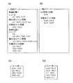
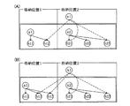
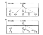
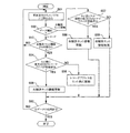
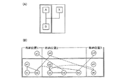
また、DB複写中にDB更新がある場合には、図2及び図3に示すようなDB複写方法となる。
複写元DBが図2(A)に示すようなデータ格納構造である場合、先の例と同様にして、複写元DBから図3(A)に示すような抽出データを抽出する。ここで、複写元DBの格納位置1のデータを抽出後、格納位置2のデータ抽出前に、図2(B)に示すように、格納位置1にレコード「b13」が追加された場合を考える。この場合には、図3(B)に示すような更新差分を取得する。更新差分は、DB更新情報及び未解決セット情報を含んで構成される。また、未解決セット情報に基づいて、図3(C)に示すようなセット表を生成する。
【0035】
そして、先の例と同様にして、レコードを複写先DBに複写し、図2(C)に示すように、解決済みセット情報に基づいて複写されたレコード間のセット関係を再現する。
【0036】
ところで、格納位置1にレコード「b13」の追加があったので、これを複写先DBに反映しなければならない。即ち、更新差分のDB更新情報に基づいて複写先DBに対して更新を行うと、図2(D)のようになる。また、DB更新によりセット表にも変更の必要性が生じたので、更新差分の未解決セット情報に基づいてセット表を更新すると、セット表は図3(D)のようになる。その後、セット表に基づいて未解決セット関係を再現すると、複写先DB上に、図2(A)と同一の論理構造を有するDB構造が再現される。
【0037】
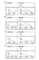
なお、本発明は、以上説明した2つの場合だけではなく、図4〜図6に示すような場合にも適用が可能である。夫々の場合を簡単に説明すると、次のようになる。
【0038】
図4は、DB更新としてデータ削除がある場合を示す。即ち、図4(A)に示すようなDB格納構造において、複写元DBの格納位置1のデータを抽出後、格納位置2のデータ抽出前に、図4(B)に示すように、格納位置1のレコード「b12」が削除された場合である。
【0039】
図5は、セット関係をポインタリストで管理する構造のDBにおいて、DB更新としてデータ追加がある場合を示す。即ち、図5(A)に示すようなDB格納構造において、複写元DBの格納位置1のデータを抽出後、格納位置2のデータ抽出前に、図5(B)に示すように、格納位置1にレコード「b13」が追加された場合である。
【0040】
図6は、セット関係をポインタリストで管理する構造のDBにおいて、DB更新としてデータ削除がある場合を示す。即ち、図6(A)に示すようなDB格納構造において、複写元DBの格納位置1のデータを抽出後、格納位置2のデータ抽出前に、図6(B)に示すように、格納位置1のレコード「b12」が削除された場合である。
【0041】
次に、以上説明した方法を実現するための具体的な構成について説明する。
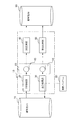
図7は、本発明に係るDB複写装置の全体構成を示す。DB複写装置は、少なくとも、中央処理装置(CPU)とメモリとを備えたコンピュータ上に構築され、メモリにロードされたプログラムに従ってソフトウエア的に動作する。
【0042】
DB複写装置10は、図7に示すように、DB抽出部20と、差分取得部30と、DB反映部40と、差分反映部50と、不揮発性記憶媒体としてのハードディスク装置等からなるファイル記憶部60と、を含んで構成される。
【0043】
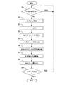
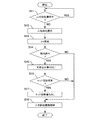
DB抽出部20は、図8に示すフローチャートに従って、複写元DB70から抽出データを抽出し、抽出データを抽出データファイル62としてファイル記憶部60に書き出す。なお、DB抽出部20が、データ複写手段,データ複写工程,データ複写機能,接続関係抽出手段,接続関係抽出工程及び接続関係抽出機能の一部として作用する。
【0044】
ステップ1(図では「S1」と略記する。以下同様)では、差分取得部30により複写元DB70のデータ抽出対象範囲が占有排他獲得されているか否かが判定される。そして、データ抽出対象範囲が占有排他獲得されていると判定されれば、占有排他獲得が解除されるまで待機する(Yes)。一方、データ抽出対象範囲が独占排他獲得されていないと判定されれば、ステップ2へと進む(No)。ここで、データ抽出対象範囲とは、例えば、図2(A)における矩形で表したDBの部分的範囲のことをいう。また、複写元DB70のデータ抽出対象範囲が占有排他獲得されている間待機する理由は、業務プログラム80により複写元DB70の更新が行われているときにデータ抽出が行われないようにすることで、複写元DB70及び複写先DB90のデータ不一致を防止するためである。
【0045】
ステップ2では、複写元DB70のデータ抽出対象範囲が占有排他獲得される。
ステップ3では、複写元DB70からレコードが抽出される。
【0046】
ステップ4では、複写元DB70から解決済みセット情報が抽出される。
ここで、ステップ3及びステップ4の処理が、データ複写手段,データ複写工程及びデータ複写機能の一部に相当する。
【0047】
ステップ5では、複写元DB70から未解決セット情報が抽出される。ここで、解決済みセット関係と未解決セット関係の区別は、例えば、DB構造定義を解析することで判断することができる。なお、ステップ5の処理が、接続関係抽出手段,接続関係抽出工程及び接続関係抽出機能の一部に相当する。
【0048】
ステップ6では、複写元DB70からデータを抽出した抽出済みデータ位置情報(具体的には、複写元DB70のデータ格納位置を特定するアドレス)が、ファイル記憶部60に書き出される。
【0049】
ステップ7では、複写元DB70のデータ抽出対象範囲の占有排他獲得が解除される。
ステップ8では、複写元DB70から抽出したレコード,解決済みセット情報及び未解決セット情報が、抽出データファイル62としてファイル記憶部60に書き出される。
【0050】
ステップ9では、複写元DB70から全データが抽出されたか否かが判定される。そして、全データが抽出されたと判定されればDB抽出部20における処理を終了し(Yes)、全データが抽出されていないと判定されればステップ1へと戻る(No)。
【0051】
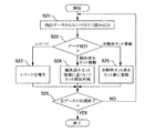
差分取得部30は、業務プログラム80からDB更新要求があったときに起動される。そして、図9に示すフローチャートに従って、データ更新対象範囲が複写元DB70から抽出済みのときに、その更新差分を更新差分ファイル64としてファイル記憶部60に書き出す。また、更新差分ファイル64は、DB複写装置10の起動時に空に初期化される。なお、差分取得部30が、更新差分取得手段として作用する。
【0052】
ステップ11では、DB抽出部20により複写元DB70のデータ更新対象範囲が占有排他獲得されているか否かが判定される。そして、データ更新対象範囲が独占排他獲得されていると判定されれば、占有排他獲得が解除されるまで待機する(Yes)。一方、データ更新対象範囲が占有排他獲得されていないと判定されれば、ステップ12へと進む(No)。ここで、複写元DB70のデータ更新対象範囲が占有排他獲得されている間待機する理由は、先のDB抽出部20における待機理由と同様である。
【0053】
ステップ12では、複写元DB70のデータ更新対象範囲が占有排他獲得される。
ステップ13では、業務プログラム80からのDB更新要求に基づいて、複写元DB70の更新が行われる。
【0054】
ステップ14では、複写元DB70のデータ更新対象範囲のデータが抽出済みであるか否かが判定される。データが抽出済みであるか否かは、ファイル記憶部60に登録された抽出済みデータ位置情報を参照することで判定することができる。そして、データ更新対象範囲のデータが抽出済みであると判定されればステップ15へと進み(Yes)、データが抽出済みでないと判定されればステップ18へと進む(No)。
【0055】
ステップ15では、更新差分ファイル64がファイル記憶部60に書き出される。
ステップ16では、業務プログラム80からのDB更新要求によりセット関係が更新されたか否かが判定される。そして、セット関係が更新されたと判定されればステップ17へと進み(Yes)、セット情報が更新差分ファイル64としてファイル記憶部60に書き出される。一方、セット関係が更新されていないと判定されればステップ18へと進む(No)。
【0056】
ここで、ステップ14〜ステップ17の処理が、更新差分取得手段に相当する。
ステップ18では、複写元DB70のデータ更新対象範囲の占有排他獲得が解除される。
【0057】
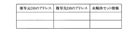
DB反映部40は、図10に示すフローチャートに従って、ファイル記憶部60から抽出データファイル62を読み込み、複写先DB90に対してレコード及び解決済みセット情報を複写すると共に、未解決セット情報を「セット表」に登録する。ここで、セット表は、図11に示すように、複写元DBのアドレス,複写先DBのアドレス及び未解決セット情報を含んで構成される。なお、DB反映部40が、データ複写手段,データ複写工程,データ複写機能,接続関係抽出手段,接続関係抽出工程及び接続関係抽出機能の一部として作用する。
【0058】
ステップ21では、ファイル記憶部60の抽出データファイル62からエントリが1つ読み込まれる。
ステップ22では、読み込まれたデータの種別に応じた分岐処理が行われる。即ち、データがレコードであればステップ23へと進み、レコードが複写先DB90に複写される。また、データが解決済みセット情報であればステップ24へと進み、解決済みセット情報に基づいて、複写先DB90に複写されたレコードのセット関係が再現される。さらに、データが未解決セット情報であればステップ25へと進み、未解決セット情報がセット表に登録される。なお、未解決セット情報のセット表への登録処理の詳細については後述する。
【0059】
ここで、ステップ23及びステップ24の処理が、データ複写手段,データ複写工程及びデータ複写機能の一部に相当する。また、ステップ25の処理が、接続関係抽出手段,接続関係抽出工程及び接続関係抽出機能の一部に相当する。
【0060】
ステップ26では、抽出データファイル62の全データの処理が終了したか否かが判定される。そして、全データの処理が終了したと判定されればDB反映部40における処理を終了し(Yes)、全データの処理が終了していないと判定されればステップ21へと戻り(No)、次のエントリの処理が行われる。
【0061】
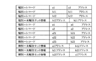
ここで、DB反映部40において、未解決セット情報をセット表に登録する処理の詳細について説明する。なお、以下の説明においては、図2及び図3の例を前提とする。
【0062】
DB抽出部20の機能により、複写元DB70から図12に示すような抽出データが抽出される。抽出データは、データ種別、並びに、レコード名及びレコードアドレス(データ種別がレコードの場合)、又は、セット関係の起点及び終点アドレス(データ種別が未解決セット情報の場合)を含んで構成される。また、解決済みセット情報は、エントリの並びの順序によって表現される。そして、セット表の生成は、図13に示すフローチャートに従って行われる。
【0063】
ステップ31では、抽出データファイル62からエントリが1つ読み込まれる。
ステップ32では、データ種別に応じた分岐処理が行われる。即ち、データがレコードであればステップ33へと進み、データが未解決セット情報であればステップ37へと進む。
【0064】
データがレコードである場合の処理を行うステップ33では、未解決セット関係があり得るレコードであるか否かが判定される。そして、未解決セット関係があり得ると判定されればステップ34へと進み(Yes)、未解決セット関係があり得ないと判定されればステップ31へと戻る(No)。
【0065】
ステップ34では、複写元DB70のレコードアドレスをキーとしてセット表が検索され、セット表にレコードアドレスが登録されているか否かが判定される。そして、セット表にレコードアドレスが登録されていると判定されればステップ35へと進み(Yes)、データ矛盾が発生していると判断して、例えば、エラーメッセージ表示等のエラー処理が実行される。一方、セット表にレコードアドレスが登録されていないと判定されればステップ36へと進み(No)、複写元DB70及び複写先DB90のレコードアドレスが、セット表に登録される。
【0066】
データが未解決セット情報である場合の処理を行うステップ37では、セット関係の起点となるレコードアドレス(複写元DBのアドレス)をキーとしてセット表が検索され、セット表にレコードアドレスが登録されているか否かが判定される。そして、セット表にレコードアドレスが登録されていると判定されればステップ38へと進み(Yes)、セット関係の終点となるレコードアドレスがセット表に登録される。一方、セット表にレコードアドレスが登録されていないと判定されればステップ39へと進み(No)、データ矛盾が発生していると判断して、例えば、エラーメッセージ表示等のエラー処理が実行される。
【0067】
ステップ40では、全データの処理が終了したか否かが判定される。そして、全データの処理が終了したと判定されればセット表の生成処理を終了し(Yes)、全データの処理が終了していないと判定されればステップ31へと戻り(No)、次のエントリの処理が行われる。
【0068】
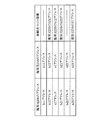
以上説明したステップ31〜ステップ40の処理によれば、図14に示すように、未解決セット情報がセット表に登録される。なお、図14では、複写元DB及び複写先DBのレコードアドレスが同一形式で表現されているが、実際には、レコードが論理複写されるため同一アドレスとは限られない。
【0069】
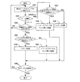
差分反映部50は、図15に示すフローチャートに従って、ファイル記憶部60から更新差分ファイル64を読み込み、複写先DB90に対してデータ更新を行うと共に、「セット表」に基づいて未解決セット情報を再現する。なお、業務プログラム80からDB更新要求がない場合には、空の更新差分ファイル64に基づくデータ更新が行われる。これにより、DB更新がない場合には、実質的にDBのデータ更新が行われないこととなる。なお、差分反映部50が、接続関係再現手段,接続関係再現工程,接続関係再現機能,データ更新手段,接続関係更新手段として作用する。
【0070】
ステップ41では、更新差分ファイル64からエントリが1つ読み込まれる。
ステップ42では、データ種別に応じた分岐処理が行われる。即ち、データがレコード更新情報であればステップ43へと進み、複写先DB90に対してレコード更新が行われる。一方、データが未解決セット情報であればステップ44へと進み、未解決セット情報に基づいてセット表が更新される。なお、セット表の更新処理の詳細については後述する。
【0071】
ここで、ステップ43の処理が、データ更新手段に相当する。また、ステップ44の処理が、接続関係更新手段に相当する。
ステップ45では、更新差分ファイル64の全データの処理が終了したか否かが判定される。そして、全データの処理が終了したと判定されればステップ46へと進み(Yes)、全データの処理が終了していないと判定されればステップ41へと戻り(No)、次のエントリの処理が行われる。
【0072】
ステップ46では、セット表から未解決セット情報が1つ読み込まれる。
ステップ47では、読み込まれた未解決セット情報に基づいて、複写先DB90に複写されたレコードのセット関係が再現される。なお、レコードのセット関係の再現処理の詳細については後述する。ここで、ステップ47の処理が、接続関係再現手段,接続関係再現工程及び接続関係再現機能に相当する。
【0073】
ステップ48では、全未解決セット情報の処理が終了したか否かが判定される。そして、全未解決セット情報の処理が終了したと判定されれば差分反映部50における処理を終了し(Yes)、全未解決セット情報の処理が終了していないと判定されればステップ46へと戻り(No)、次の未解決セット情報の処理が行われる。
【0074】
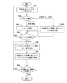
ここで、差分反映部50において、セット表を更新する処理の詳細について説明する。なお、以下の説明においては、図2及び図3の例を前提とする。
差分取得部30の機能により、図16に示すような更新差分が生成される。更新差分は、データ種別、並びに、レコード名及びレコードアドレス(データ種別がレコード更新情報の場合)、又は、セット関係の起点及び終点アドレス(データ種別が未解決セット情報の場合)を含んで構成される。そして、セット表の更新は、図17に示すフローチャートに従って行われる。
【0075】
ステップ51では、更新差分ファイル64からエントリが1つ読み込まれる。
ステップ52では、データ種別に応じた分岐処理が行われる。即ち、データがレコードであればステップ53へと進み、データが未解決セット情報であればステップ57へと進む。
【0076】
データがレコードである場合の処理を行うステップ53では、未解決セット関係があり得るレコードであるか否かが判定される。そして、未解決セット関係があり得ると判定されればステップ54へと進み(Yes)、未解決セット関係があり得ないと判定されればステップ51へと戻る(No)。
【0077】
ステップ54では、複写元DB70のレコードアドレスをキーとしてセット表が検索され、セット表にレコードアドレスが登録されているか否かが判定される。そして、セット表にレコードアドレスが登録されていると判定されればステップ55へと進み(Yes)、セット関係の終点となるレコードアドレスにより未解決セット情報が更新される。一方、セット表にレコードアドレスが登録されていないと判定されればステップ56へと進み(No)、複写元DB70及び複写先DB90のレコードアドレスが、セット表に登録される。
【0078】
データが未解決セット情報である場合の処理を行うステップ57では、セット関係の起点となるレコードアドレスをキーとしてセット表が検索され、セット表にレコードアドレスが登録されているか否かが判定される。そして、セット表にレコードアドレスが登録されていると判定されればステップ58へと進み(Yes)、セット関係の終点となるレコードアドレスにより未解決セット情報が更新される。一方、セット表にレコードアドレスが登録されていないと判定されればステップ59へと進み(No)、未解決セット情報が無視される。
【0079】
ステップ60では、全データの処理が終了したか否かが判定される。そして、全データの処理が終了したと判定されればセット表の更新処理を終了し(Yes)、全データの処理が終了していないと判定されればステップ51へと戻り(No)、次のエントリの処理が行われる。
【0080】
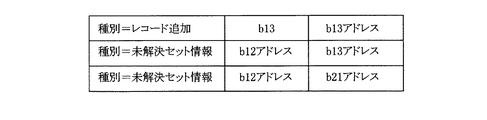
以上説明したステップ51〜ステップ60の処理によれば、セット表が図18に示すように更新される。即ち、業務プログラム80によるDB更新内容が、セット表に反映されることとなる。
【0081】
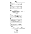
次に、差分反映部50において、セット表に基づくセット関係の再現処理の詳細について、図19のフローチャートを参照して説明する。なお、以下の説明においては、図18のセット表に基づいて、レコード間のセット関係を再現するものとする。
【0082】
ステップ61では、セット表からエントリが1つ読み込まれる。
ステップ62では、複写元DB70のレコードアドレスがセット関係の起点に位置付けられる。
【0083】
ステップ63では、エントリの未解決セット情報が登録されているか否かが判定される。そして、未解決セット情報が登録されていればステップ64へと進み(Yes)、未解決セット情報が登録されていなければステップ61へと戻り、次のエントリの処理が行われる。
【0084】
ステップ64では、未解決セット情報に登録されているレコードアドレスをキーとしてセット表が検索され、このレコードアドレスが登録されている複写元DB70のエントリが読み込まれる。
【0085】
ステップ65では、エントリの複写先DB90のレコードアドレスがセット関係の終点に位置付けられる。
ステップ66では、位置付けられたセット関係の起点と終点とが接続され、レコード間のセット関係が再現される。
【0086】
ステップ67では。セット表の全エントリの処理が終了したか否かが判定される。そして、全エントリの処理が終了したと判定されればセット関係の再現処理を終了し(Yes)、全エントリの処理が終了していないと判定されればステップ61へと戻る(No)。
【0087】
以上説明した構成のDB複写装置によれば、レコード間の接続関係がデータベース全体に及ぶ場合であっても、分割された領域単位でのデータベース複写が行われ、その後、異なる領域に夫々含まれるレコード間の接続関係が再現される。このため、従来技術のように、広範囲に亘るデータベースの排他占有が不要となり、例えば、オンラインシステムの稼動中にデータベース複写を行うことが可能となる。従って、データベース構造の如何にかかわらずデータベース複写が効率的に行われ、データベース複写の係る汎用性を高めることができる。
【0088】
また、レコード及びレコード間の接続関係が複写された複写元データベースの領域に対してデータベース更新要求があったときには、データベース更新要求による更新差分が取得される。そして、取得された更新差分に基づいて、複写先データベースに複写されたレコード及びレコード間の接続関係、並びに、異なる領域に夫々含まれるレコード間の接続関係が更新される。その後、更新された異なる領域に含まれるレコード間の接続関係に基づいて、複写先データベースに複写されたレコード間の接続関係が再現される。従って、データベース複写中であっても、例えば、業務プログラムからのデータベース更新要求を処理することが可能となり、種々のオンラインシステムへ適用することができる。
【0089】
なお、本実施形態では、セット表をファイル記憶部60に登録したが、セット表をメモリ上に登録する構成としてもよい。但し、セット表は、一般的に大規模になること及びシステムダウン時のデータ保証を考慮すると、本実施形態のように、不揮発性記憶媒体に登録することが望ましい。
【0090】
また、本実施形態では、セット関係は、全ての更新差分を反映した後に再現する構成を採用しているが、DB抽出完了後であれば任意の時点で行うことができる。例えば、処理完了判定手段としてDB抽出が完了した旨の情報を更新差分取得中に取得し、差分反映部がこれを認識した時点で行う方法も考えられる。この場合、DB抽出完了後のセット表の更新がなくなるため,本実施形態よりも効率が良いという利点がある。
【0091】
このような機能を実現するプログラムを、例えば、磁気テープ,磁気ディスク,磁気ドラム,ICカード,CD−ROM等の可搬記録媒体に記録しておけば、本発明に係るDB複写プログラムを市場に流通させることができる。そして、かかる記録媒体を取得した者は、一般的なコンピュータシステムを利用して、本発明に係るDB複写装置を容易に構築することができる。
【0092】
【発明の効果】
以上説明したように、請求項1又は請求項5に記載の発明によれば、レコード間の接続関係がデータベース全体に及ぶ場合であっても、分割された領域単位でのデータベース複写が行われ、その後、異なる領域に夫々含まれるレコード間の接続関係が再現される。従って、データベース構造の如何にかかわらずデータベース複写が効率的に行われ、データベース複写の係る汎用性を高めることができる。
【0093】
請求項2記載の発明によれば、データベース複写中にデータベース更新要求があっても、その内容を複写先データベースに反映することができる。従って、データベース複写中であっても、例えば、業務プログラムからのデータベース更新要求を処理することが可能となり、種々のオンラインシステムへ適用することができる。
【0094】
請求項3記載の発明によれば、複写元データベースに対する処理が完了すると、接続関係及び更新差分に基づいて、複写先データベースに複写されたレコード間の接続関係が再現及び更新される。従って、請求項2記載の発明のような抽出された接続関係の更新処理が不要となり、データベース複写効率をさらに向上することができる。
【0095】
請求項4記載の発明によれば、コンピュータシステムのメモリ消費が抑制されるので、コンピュータシステムのハードウエア上の要求を緩和することができる。また、コンピュータシステムがダウンしても接続関係が保持されるので、再起動時にデータベースを回復することができる。
【0096】
請求項6記載の発明によれば、請求項1又は請求項5に記載の発明の効果に加え、本発明に係るデータベース複写プログラムを市場に流通させることができる。そして、かかる記録媒体を取得した者は、一般的なコンピュータシステムを利用して、本発明に係るデータベース複写装置を容易に構築することができる。
【図面の簡単な説明】
【図1】データベースの更新がない場合の本発明の原理を示し、(A)は複写元データベースのデータ格納構造、(B)は複写元データベースから抽出した抽出データ、(C)は抽出データに基づいて生成されたセット表、(D)は複写先データベースに複写されたレコード及び解決済みセット情報を夫々説明する図である。
【図2】データベースの更新がある場合の本発明の原理を示し、(A)は複写元データベースのデータ格納構造、(B)はデータベースの更新内容、(C)は複写先データベースに複写されたレコード及び解決済みセット情報、(D)はデータベースの更新内容を反映した複写先データベースを夫々説明する図である。
【図3】データベースの更新がある場合の本発明の原理を示し、(A)は複写元データベースから抽出した抽出データ、(B)はデータベースの更新内容に応じて生成された更新差分、(C)は抽出データに基づいて生成されたセット表、(D)は更新差分により更新されたセット表を夫々説明する図である。
【図4】本発明が適用可能な他のデータ格納構造の一例を示す図である。
【図5】本発明が適用可能な他のデータ格納構造の一例を示す図である。
【図6】本発明が適用可能な他のデータ格納構造の一例を示す図である。
【図7】本発明に係るデータベース複写装置の全体構成図である。
【図8】DB抽出部における処理内容を示すフローチャートである。
【図9】差分取得部における処理内容を示すフローチャートである。
【図10】DB反映部における処理内容を示すフローチャートである。
【図11】セット表の説明図である。
【図12】抽出データの説明図である。
【図13】セット表の生成処理内容を示すフローチャートである。
【図14】セット表の生成処理によって生成されたセット表の具体例を示す図である。
【図15】差分反映部における処理内容を示すフローチャートである。
【図16】差分取得部によって生成される更新差分の具体例を示す図である。
【図17】セット表の更新処理内容を示すフローチャートである。
【図18】セット表の更新処理によって更新されたセット表の具体例を示す図である。
【図19】セット関係の再現処理内容を示すフローチャートである。
【図20】従来技術の問題点を示し、(A)はシステムを停止して保守等を行う運用形態、(B)はシステムの無停止運用形態、(C)は2つのシステムを交互に切り替えて保守等を行う運用形態を夫々説明する図である。
【図21】システムを切り替えるときのデータベース複写処理の概要説明図である。
【図22】従来技術ではデータベース複写が短時間でできない一例を示し、(A)はn:1型のデータ構造、(B)はn:1型のデータ構造の具体例を夫々説明する図である。
【図23】従来技術ではデータベース複写が短時間でできない一例を示し、(A)は論理構造、(B)はデータ格納構造を夫々説明する図である。
【符号の説明】
10…データベース複写装置
20…DB抽出部
30…差分取得部
40…DB反映部
50…差分反映部
60…ファイル記憶部
64…更新差分ファイル
70…複写元データベース
90…複写先データベース[0001]
BACKGROUND OF THE INVENTION
The present invention relates to a database copying technique, and more particularly to a technique for improving versatility.
[0002]
[Prior art]
In recent years, with the internationalization of business and 24-hour services, there is an increasing need to operate computer systems that execute business programs without interruption.
[0003]
By the way, in a computer system, it is necessary to stop the system for maintenance of hardware or the like. In a non-stop operation of a computer system, maintenance cannot be performed because the system cannot be stopped. For this reason, an operation mode in which two sets of computer systems are prepared and the operation is alternately switched to stop one system and perform maintenance can be considered.
[0004]
However, since the maintenance work includes maintenance of the disk device, the same disk device cannot be shared between the two computer systems. Therefore, it is necessary to use a separate disk device for each system, and a database (hereinafter referred to as “DB”) must be copied when switching operations. Copying the DB must be fast enough so that the service to users of the computer system does not stop.
[0005]
In order to solve such a problem, the present applicant has proposed a copy system of an update database (refer to Japanese Patent Laid-Open No. 10-207754). This technology guarantees DB equivalence by acquiring and reflecting update differences only when the business program updates the DB for extracted data. At the time of data extraction, the extraction target range is exclusively occupied, and the records within the range and the connection relationship between the records (hereinafter referred to as “set relationship”) are extracted at once.
[0006]
[Problems to be solved by the invention]
However, depending on the DB structure, there is a possibility that the set relationship extends to the entire DB, and the following problems may occur. That is, when the set relationship extends to the entire DB, the entire DB is exclusively occupied and data is extracted, and thus the DB cannot be updated substantially. Therefore, in the prior art, there is a limitation on the DB structure with respect to DB copying, and the versatility is low.
[0007]
Therefore, in view of the above-described conventional problems, an object of the present invention is to provide a database copying technique that can efficiently perform DB copying regardless of the DB structure and has improved versatility.
[0008]
[Means for Solving the Problems]
Therefore, the invention according to
[0009]
According to such a configuration, the database is copied as follows.
(1) The copy source database is divided into predetermined areas, and the records included in each area and the connection relationship between the records are copied to the copy destination database.
[0010]
(2) A connection relationship between records included in different areas is extracted from the copy source database.
(3) Based on the extracted connection relationship, the connection relationship between records copied to the copy destination database is reproduced.
[0011]
Therefore, even when the connection relationship between records extends over the entire database, database copying is performed in units of divided areas, and thereafter, the connection relationships between records included in different regions are reproduced. This eliminates the need for exclusive occupancy of the database over a wide range as in the prior art. For example, database copying can be performed while the online system is in operation.
[0012]
According to the second aspect of the present invention, when there is a database update request for a copy source database area in which a record and a connection relation between the records are copied by the data copying unit, an update difference due to the database update request is calculated. An update difference acquisition means for acquiring, and a data update means for updating a record copied to a copy destination database by the data copying means and a connection relation between the records based on the update difference acquired by the update difference acquisition means; And a connection relation updating means for updating the connection relation extracted by the connection relation extracting means on the basis of the update difference obtained by the update difference obtaining means.
[0013]
According to this configuration, when there is a database update request for a copy source database area in which a record and a connection relationship between records are copied, an update difference due to the database update request is acquired. That is, even if an update is performed on an area where a record or the like in the copy source database has been copied, the update is not reflected in the copy destination database, and thus an update difference is acquired. Then, based on the acquired update difference, the records copied in the copy destination database, the connection relationship between the records, and the connection relationship between the records respectively included in different areas are updated. Thereafter, the connection relation between the records copied to the copy destination database is reproduced based on the connection relation between the records included in the updated different areas.
[0014]
According to a third aspect of the present invention, there is provided a processing completion judging means for judging whether or not the processing for the copy source database by the data copying means and the connection relation extracting means has been completed, and a record between the records by the data copying means. An update difference acquisition unit that acquires an update difference according to the database update request when there is a database update request for an area of the copy source database in which the connection relationship is copied, and the connection relationship reproduction unit includes: The data copy based on the connection relation extracted by the connection relation extraction means and the update difference acquired by the update difference acquisition means when the processing completion determination means determines that the processing for the copy source database is completed. A mechanism for reproducing and updating the connection relationship between records copied to the copy destination database by means of And characterized in that.
[0015]
According to this configuration, when there is a database update request for a copy source database area in which a record and a connection relationship between records are copied, an update difference due to the database update request is acquired. When the processing for the copy source database is completed, the connection relationship between the records copied to the copy destination database is reproduced and updated based on the connection relationship and the update difference. Therefore, it is not necessary to update the extracted connection relationship as in the second aspect of the invention.
[0016]
The invention described in claim 4 is characterized in that the connection relation extracted by the connection relation extraction means is held on a nonvolatile storage medium.
Here, the “nonvolatile storage medium” refers to a storage medium that retains its contents even when the power is turned off, such as a hard disk device.
[0017]
According to such a configuration, even if the connection relationship extracted by the connection relationship extraction unit increases, memory consumption of the computer system is suppressed. Even if the computer system goes down during database copying, the connection relationship is maintained, so that the database can be recovered at the time of restart.
[0018]
The invention described in
[0019]
According to such a configuration, the database is copied as follows.
(1) The copy source database is divided into predetermined areas, and the records included in each area and the connection relationship between the records are copied to the copy destination database.
[0020]
(2) A connection relationship between records included in different areas is extracted from the copy source database.
(3) Based on the extracted connection relationship, the connection relationship between records copied to the copy destination database is reproduced.
[0021]
Therefore, even when the connection relationship between records extends over the entire database, database copying is performed in units of divided areas, and thereafter, the connection relationships between records included in different regions are reproduced. This eliminates the need for exclusive occupancy of the database over a wide range as in the prior art. For example, database copying can be performed while the online system is in operation.
[0022]
The invention according to claim 6 is different from the copy source database in that the copy source database is divided into predetermined areas and the records included in each area and the connection relationship between the records are copied to the copy destination database. A connection relation extracting function for extracting a connection relation between records included in each area, and a record between records copied to the copy destination database by the data copying function based on the connection relation extracted by the connection relation extracting function. A database copy program for realizing a connection relationship reproduction function for reproducing a connection relationship is recorded on a recording medium.
[0023]
Here, the “recording medium” refers to a medium that can reliably record various kinds of information and can be reliably taken out as necessary, such as a magnetic tape, a magnetic disk, a magnetic drum, an IC card, and a CD-ROM. This applies to portable recording media.
[0024]
According to such a configuration, the database copying program for realizing the data copying function, the connection relation extracting function, and the connection relation reproducing function is recorded on the recording medium. Therefore, if there is a recording medium in which such a program is recorded, a database copying apparatus according to the present invention can be easily constructed using a general computer system.
[0025]
DETAILED DESCRIPTION OF THE INVENTION
Hereinafter, the present invention will be described in detail with reference to the accompanying drawings.
Before describing the present invention in detail, the problems of the prior art will be described again.
[0026]
FIG. 20 shows an example of the operation mode of the online system. In the conventional operation example, as shown in FIG. 20 (A), work that is premised on system stoppage such as maintenance is performed within the online service stoppage time (in the figure, 22:00 to 7:00 the next day). . However, when an online system is operated without stopping by a 24-hour service or the like, a single computer system cannot perform a work based on the premise that the system is stopped as shown in FIG. For this reason, as shown in FIG. 20C, by using two computer systems and alternately switching the operation of the system, it is possible to perform an operation based on the premise that the system is stopped.
[0027]
In order to switch between the two computer systems alternately, it is necessary to copy the DB as described above. The DB copying process will be described with reference to FIG. Note that DB copying is performed from the
[0028]
(1) Prior to system switching, data is extracted from the
(2) In conjunction with DB extraction, acquisition of service request update differences for the
[0029]
(3) The extracted data is copied to the
(4)
[0030]
(5) The update difference is reflected to make the
[0031]
(6) Since the DBs of the
In the DB copying according to the prior art described above, the data extraction range is exclusively occupied, and the data and set relationships within the range are extracted all at once. Therefore, when the set relationship covers the entire DB, the DB update can be performed in a short time. It becomes impossible. That is, in the case of an “n: 1 type” DB as shown in FIG. 22 and a data storage structure as shown in FIG. 23, there is a set relationship across different storage positions. The entire DB must be exclusively occupied. Since a DB in an online system or the like is generally large-scale, if the entire DB is exclusively occupied, a DB copy in a short time cannot be expected. Therefore, it is impossible to switch the computer system in a short time.
[0032]
Next, a method for solving such problems of the prior art will be described.
FIG. 1 shows a DB copying method when there is no DB update during DB copying.
When the copy source DB has a data storage structure as shown in FIG. 1A, extracted data as shown in FIG. 1B is extracted from the copy source DB. The extracted data includes a record, resolved set information, and unresolved set information for each storage position. The record means the data itself stored in the copy source DB, that is, the data itself such as “baseball club”, “one section”, “Yamada” if the data structure is as shown in FIG. Solved set information refers to information that identifies a set relationship that cannot have a set relationship between different storage positions. Unresolved set information refers to information that identifies a set relationship that can have a set relationship between different storage positions. When the extracted data can be extracted, a set table (details will be described later) as shown in FIG. 1C is generated from the unresolved set information.
[0033]
Then, the record is copied to the copy destination DB, and the set relation between the copied records is reproduced based on the resolved set information as shown in FIG. Thereafter, when the unresolved set relationship is reproduced based on the set table, a DB structure having the same logical structure as that in FIG. 1A is reproduced on the copy destination DB.
[0034]
When there is DB update during DB copying, the DB copying method as shown in FIGS. 2 and 3 is used.
When the copy source DB has a data storage structure as shown in FIG. 2A, the extracted data as shown in FIG. 3A is extracted from the copy source DB in the same manner as the previous example. Here, consider the case where the record “b13” is added to the
[0035]
Then, similarly to the previous example, the record is copied to the copy destination DB, and the set relationship between the copied records is reproduced based on the resolved set information as shown in FIG.
[0036]
Incidentally, since the record “b13” has been added to the
[0037]
Note that the present invention can be applied not only to the two cases described above, but also to the cases shown in FIGS. Each case will be briefly described as follows.
[0038]
FIG. 4 shows a case where there is data deletion as DB update. That is, in the DB storage structure as shown in FIG. 4A, after extracting the data at the
[0039]
FIG. 5 shows a case where data is added as a DB update in a DB having a structure in which the set relation is managed by a pointer list. That is, in the DB storage structure as shown in FIG. 5A, after extracting the data at the
[0040]
FIG. 6 shows a case where there is data deletion as DB update in a DB having a structure in which the set relation is managed by a pointer list. That is, in the DB storage structure as shown in FIG. 6A, after extracting the data at the
[0041]
Next, a specific configuration for realizing the method described above will be described.
FIG. 7 shows the overall configuration of the DB copying apparatus according to the present invention. The DB copying apparatus is constructed on a computer including at least a central processing unit (CPU) and a memory, and operates in software according to a program loaded in the memory.
[0042]
As shown in FIG. 7, the
[0043]
The
[0044]
In step 1 (abbreviated as “S1” in the figure, the same applies hereinafter), the
[0045]
In
In
[0046]
In step 4, resolved set information is extracted from the
Here, the processing in
[0047]
In
[0048]
In step 6, extracted data position information (specifically, an address specifying the data storage position of the copy source DB 70) obtained by extracting data from the
[0049]
In step 7, the exclusive exclusive acquisition of the data extraction target range of the
In step 8, the record extracted from the
[0050]
In
[0051]
The
[0052]
In step 11, it is determined whether the
[0053]
In step 12, exclusive exclusive acquisition of the data update target range of the
In step 13, the
[0054]
In step 14, it is determined whether or not the data in the data update target range of the
[0055]
In step 15, the
In step 16, it is determined whether or not the set relationship has been updated by a DB update request from the
[0056]
Here, the process of step 14-step 17 is equivalent to an update difference acquisition means.
In step 18, the exclusive exclusive acquisition of the data update target range of the
[0057]
The
[0058]
In step 21, one entry is read from the extracted
In step 22, branch processing is performed according to the type of the read data. That is, if the data is a record, the process proceeds to step 23, where the record is copied to the
[0059]
Here, the processing of step 23 and step 24 corresponds to a part of the data copying means, the data copying process, and the data copying function. Further, the processing in step 25 corresponds to a part of the connection relationship extracting means, the connection relationship extracting step, and the connection relationship extracting function.
[0060]
In step 26, it is determined whether or not the processing of all data in the extracted
[0061]
Here, details of the process of registering unresolved set information in the set table in the
[0062]
The extracted data as shown in FIG. 12 is extracted from the
[0063]
In step 31, one entry is read from the extracted
In step 32, branch processing according to the data type is performed. That is, if the data is a record, the process proceeds to step 33, and if the data is unresolved set information, the process proceeds to step 37.
[0064]
In step 33 in which processing is performed when the data is a record, it is determined whether or not the record can have an unresolved set relationship. If it is determined that there can be an unresolved set relationship, the process proceeds to step 34 (Yes), and if it is determined that there is no unsolved set relationship, the process returns to step 31 (No).
[0065]
In step 34, the set table is searched using the record address of the
[0066]
In step 37 where processing is performed when the data is unresolved set information, the set table is searched using the record address (address of the copy source DB) as a starting point of the set relationship, and the record address is registered in the set table. It is determined whether or not there is. If it is determined that the record address is registered in the set table, the process proceeds to step 38 (Yes), and the record address that is the end point of the set relationship is registered in the set table. On the other hand, if it is determined that the record address is not registered in the set table, the process proceeds to step 39 (No), and it is determined that data inconsistency has occurred, and error processing such as error message display is executed. The
[0067]
In
[0068]
According to the processing from step 31 to step 40 described above, unresolved set information is registered in the set table as shown in FIG. In FIG. 14, the record addresses of the copy source DB and the copy destination DB are expressed in the same format, but in reality, the records are logically copied, so they are not necessarily the same address.
[0069]
The
[0070]
In step 41, one entry is read from the
In step 42, branch processing according to the data type is performed. That is, if the data is record update information, the process proceeds to step 43, and the record is updated in the
[0071]
Here, the process of step 43 corresponds to a data update means. Further, the process of step 44 corresponds to a connection relationship update unit.
In step 45, it is determined whether or not the processing of all data in the
[0072]
In step 46, one unresolved set information is read from the set table.
In step 47, the set relationship of the records copied to the
[0073]
In step 48, it is determined whether or not the processing of all unsolved set information has been completed. If it is determined that the processing of all unresolved set information has been completed, the processing in the
[0074]
Here, details of the process of updating the set table in the
An update difference as shown in FIG. 16 is generated by the function of the
[0075]
In step 51, one entry is read from the
In step 52, branch processing according to the data type is performed. That is, if the data is a record, the process proceeds to step 53, and if the data is unsolved set information, the process proceeds to step 57.
[0076]
In step 53 in which processing is performed when the data is a record, it is determined whether or not the record can have an unresolved set relationship. If it is determined that there can be an unresolved set relationship, the process proceeds to step 54 (Yes), and if it is determined that there is no unsolved set relationship, the process returns to step 51 (No).
[0077]
In step 54, the set table is searched using the record address of the
[0078]
In step 57 where processing is performed when the data is unresolved set information, the set table is searched using the record address that is the starting point of the set relationship as a key, and it is determined whether or not the record address is registered in the set table. . If it is determined that the record address is registered in the set table, the process proceeds to step 58 (Yes), and the unresolved set information is updated with the record address that is the end point of the set relationship. On the other hand, if it is determined that the record address is not registered in the set table, the process proceeds to step 59 (No), and the unresolved set information is ignored.
[0079]
In
[0080]
According to the processing of step 51 to step 60 described above, the set table is updated as shown in FIG. That is, the DB update content by the
[0081]
Next, the details of the set relationship reproduction process based on the set table in the
[0082]
In step 61, one entry is read from the set table.
In
[0083]
In step 63, it is determined whether or not the unresolved set information of the entry is registered. If unresolved set information is registered, the process proceeds to step 64 (Yes). If unresolved set information is not registered, the process returns to step 61 to process the next entry.
[0084]
In
[0085]
In step 65, the record address of the
In step 66, the start point and end point of the positioned set relationship are connected, and the set relationship between records is reproduced.
[0086]
In step 67. It is determined whether or not the processing of all entries in the set table has been completed. If it is determined that all entries have been processed, the set relationship reproduction process is terminated (Yes). If it is determined that all entries have not been processed, the process returns to step 61 (No).
[0087]
According to the DB copying apparatus having the above-described configuration, even if the connection relation between records extends to the entire database, database copying is performed in units of divided areas, and thereafter records included in different areas are recorded. The connection relationship between them is reproduced. This eliminates the need for exclusive occupancy of the database over a wide range as in the prior art. For example, database copying can be performed while the online system is in operation. Therefore, database copying is efficiently performed regardless of the database structure, and versatility related to database copying can be enhanced.
[0088]
Further, when there is a database update request for the copy source database area in which the record and the connection relation between the records are copied, an update difference by the database update request is acquired. Then, based on the acquired update difference, the records copied in the copy destination database, the connection relationship between the records, and the connection relationship between the records respectively included in different areas are updated. Thereafter, the connection relation between the records copied to the copy destination database is reproduced based on the connection relation between the records included in the updated different areas. Therefore, even during database copying, for example, a database update request from a business program can be processed and can be applied to various online systems.
[0089]
In this embodiment, the set table is registered in the
[0090]
Further, in the present embodiment, the set relationship employs a configuration that is reproduced after reflecting all update differences, but can be performed at any time as long as the DB extraction is completed. For example, a method of acquiring information indicating that the DB extraction has been completed as the processing completion determination unit during update difference acquisition, and performing when the difference reflection unit recognizes the information is also conceivable. In this case, since the set table is not updated after the DB extraction is completed, there is an advantage that it is more efficient than this embodiment.
[0091]
If a program that realizes such a function is recorded on a portable recording medium such as a magnetic tape, a magnetic disk, a magnetic drum, an IC card, or a CD-ROM, the DB copying program according to the present invention is put on the market. It can be distributed. A person who has obtained such a recording medium can easily construct a DB copying apparatus according to the present invention using a general computer system.
[0092]
【The invention's effect】
As described above, according to the invention described in
[0093]
According to the second aspect of the present invention, even if there is a database update request during database copying, the contents can be reflected in the copy destination database. Therefore, even during database copying, for example, a database update request from a business program can be processed and can be applied to various online systems.
[0094]
According to the third aspect of the present invention, when the processing for the copy source database is completed, the connection relationship between the records copied to the copy destination database is reproduced and updated based on the connection relationship and the update difference. Therefore, the update process of the extracted connection relation as in the invention described in
[0095]
According to the invention described in claim 4, since the memory consumption of the computer system is suppressed, the hardware requirements of the computer system can be relaxed. Even if the computer system goes down, the connection relationship is maintained, so that the database can be recovered at the time of restart.
[0096]
According to the invention described in claim 6, in addition to the effect of the invention described in
[Brief description of the drawings]
FIG. 1 shows the principle of the present invention when there is no database update, (A) shows a data storage structure of a copy source database, (B) shows extracted data extracted from the copy source database, and (C) shows extracted data. (D) is a diagram for explaining records copied to the copy destination database and resolved set information, respectively.
FIG. 2 shows the principle of the present invention when a database is updated, (A) is a data storage structure of a copy source database, (B) is a database update content, and (C) is copied to a copy destination database. (D) is a diagram for explaining the copy destination database reflecting the updated contents of the database.
FIG. 3 shows the principle of the present invention when there is a database update, (A) is extracted data extracted from the copy source database, (B) is an update difference generated according to the database update content, (C () Is a set table generated based on the extracted data, and (D) is a diagram for explaining the set table updated by the update difference.
FIG. 4 is a diagram showing an example of another data storage structure to which the present invention can be applied.
FIG. 5 is a diagram showing an example of another data storage structure to which the present invention is applicable.
FIG. 6 is a diagram showing an example of another data storage structure to which the present invention can be applied.
FIG. 7 is an overall configuration diagram of a database copying apparatus according to the present invention.
FIG. 8 is a flowchart showing processing contents in a DB extraction unit.
FIG. 9 is a flowchart illustrating processing contents in a difference acquisition unit.
FIG. 10 is a flowchart showing processing contents in a DB reflection unit.
FIG. 11 is an explanatory diagram of a set table.
FIG. 12 is an explanatory diagram of extracted data.
FIG. 13 is a flowchart showing the contents of set table generation processing;
FIG. 14 is a diagram illustrating a specific example of a set table generated by a set table generation process;
FIG. 15 is a flowchart showing processing contents in a difference reflection unit;
FIG. 16 is a diagram illustrating a specific example of an update difference generated by a difference acquisition unit.
FIG. 17 is a flowchart showing details of set table update processing;
FIG. 18 is a diagram illustrating a specific example of a set table updated by a set table update process.
FIG. 19 is a flowchart showing the contents of a set relationship reproduction process;
20A and 20B show problems of the prior art, in which FIG. 20A shows an operation mode in which a system is stopped and maintenance is performed, FIG. 20B shows a system non-stop operation mode, and FIG. It is a figure explaining the operation | movement form which performs maintenance etc., respectively.
FIG. 21 is a schematic explanatory diagram of database copy processing when switching systems;
FIGS. 22A and 22B show an example in which database copying cannot be performed in a short time in the prior art. FIG. 22A is a diagram illustrating an n: 1 type data structure, and FIG. 22B is a diagram illustrating a specific example of an n: 1 type data structure. is there.
FIGS. 23A and 23B show an example in which database copying cannot be performed in a short time in the prior art. FIG. 23A is a diagram illustrating a logical structure and FIG. 23B is a diagram illustrating a data storage structure.
[Explanation of symbols]
10 ... Database copying machine
20 ... DB extraction unit
30 ... Difference acquisition unit
40 ... DB reflection part
50 ... Difference reflection part
60: File storage unit
64 ... update difference file
70 ... Copy source database
90 ... Copy destination database
Claims (6)
前記複写元データベースから、異なった領域に夫々含まれるレコード間の接続関係を抽出する接続関係抽出手段と、
該接続関係抽出手段により抽出された接続関係に基づいて、前記データ複写手段により複写先データベースに複写されたレコード間の接続関係を再現する接続関係再現手段と、
を含んで構成されたことを特徴とするデータベース複写装置。Data copying means for dividing the copy source database into predetermined areas and copying the records included in each area and the connection relationship between the records to the copy destination database;
Connection relation extracting means for extracting connection relations between records respectively included in different areas from the copy source database;
Based on the connection relation extracted by the connection relation extraction means, connection relation reproduction means for reproducing the connection relation between records copied to the copy destination database by the data copying means;
A database copying apparatus comprising:
該更新差分取得手段により取得された更新差分に基づいて、前記データ複写手段により複写先データベースに複写されたレコード及び該レコード間の接続関係を更新するデータ更新手段と、
当該更新差分取得手段により取得された更新差分に基づいて、前記接続関係抽出手段により抽出された接続関係を更新する接続関係更新手段と、
を含んだ構成である請求項1記載のデータベース複写装置。An update difference acquisition means for acquiring an update difference due to the database update request when there is a database update request for a copy source database area in which a record and a connection relation between the records are copied by the data copying means;
Based on the update difference acquired by the update difference acquisition means, the data update means for updating the record copied to the copy destination database by the data copy means and the connection relationship between the records;
Based on the update difference acquired by the update difference acquisition unit, a connection relationship update unit that updates the connection relationship extracted by the connection relationship extraction unit;
The database copying apparatus according to claim 1, comprising:
前記データ複写手段によりレコード及び該レコード間の接続関係が複写された複写元データベースの領域に対してデータベース更新要求があったときに、該データベース更新要求による更新差分を取得する更新差分取得手段と、
を備え、
前記接続関係再現手段は、前記処理完了判定手段により複写元データベースに対する処理が完了したと判定されたときに、前記接続関係抽出手段により抽出された接続関係及び前記更新差分取得手段により取得された更新差分に基づいて、前記データ複写手段により複写先データベースに複写されたレコード間の接続関係を再現及び更新する構成である請求項1記載のデータベース複写装置。A process completion judging means for judging whether or not the processing for the copy source database by the data copying means and the connection relation extracting means is completed;
An update difference acquisition means for acquiring an update difference due to the database update request when there is a database update request for a copy source database area in which a record and a connection relation between the records are copied by the data copying means;
With
The connection relation reproduction means is connected to the connection relation extracted by the connection relation extraction means and the update acquired by the update difference acquisition means when the processing completion determination means determines that the processing for the copy source database is completed. 2. The database copying apparatus according to claim 1, wherein the database copying apparatus is configured to reproduce and update a connection relation between records copied to the copy destination database by the data copying means based on the difference.
接続関係抽出手段が、前記複写元データベースから、異なった領域に夫々含まれるレコード間の接続関係を抽出する接続関係抽出工程と、
接続関係再現手段が、該接続関係抽出工程により抽出された接続関係に基づいて、前記データ複写工程により複写先データベースに複写されたレコード間の接続関係を再現する接続関係再現工程と、
を含んで構成されたことを特徴とするデータベース複写方法。 A data copying step in which the data copying means divides the copy source database into predetermined areas and copies the records included in each area and the connection relationship between the records to the copy destination database;
A connection relationship extracting means for extracting a connection relationship between records respectively included in different areas from the copy source database; and
A connection relationship reproduction means for reproducing a connection relationship between records copied to the copy destination database by the data copying step based on the connection relationship extracted by the connection relationship extraction step;
A database copying method comprising:
複写元データベースを所定領域に分割し、各領域に含まれるレコード及び該レコード間の接続関係を複写先データベースに複写するデータ複写機能と、
前記複写元データベースから、異なった領域に夫々含まれるレコード間の接続関係を抽出する接続関係抽出機能と、
該接続関係抽出機能により抽出された接続関係に基づいて、前記データ複写機能により複写先データベースに複写されたレコード間の接続関係を再現する接続関係再現機能と、
を実現させるためのデータベース複写プログラムを記録したコンピュータ読み取り可能な記録媒体。 On the computer,
A data copy function for dividing the copy source database into predetermined areas, and copying records included in each area and the connection relation between the records to the copy destination database;
A connection relation extraction function for extracting connection relations between records respectively included in different areas from the copy source database;
Based on the connection relation extracted by the connection relation extraction function, a connection relation reproduction function for reproducing the connection relation between records copied to the copy destination database by the data copying function;
Computer readable recording medium recording a database replication program for letting realized.
Priority Applications (2)
| Application Number | Priority Date | Filing Date | Title |
|---|---|---|---|
| JP14923199A JP4046893B2 (en) | 1999-05-28 | 1999-05-28 | Database copying apparatus, database copying method, and computer-readable recording medium recording a database copying program |
| US09/427,935 US6636876B1 (en) | 1999-05-28 | 1999-10-27 | Database copy apparatus, database copy method and recording medium recorded with database copy program |
Applications Claiming Priority (1)
| Application Number | Priority Date | Filing Date | Title |
|---|---|---|---|
| JP14923199A JP4046893B2 (en) | 1999-05-28 | 1999-05-28 | Database copying apparatus, database copying method, and computer-readable recording medium recording a database copying program |
Publications (2)
| Publication Number | Publication Date |
|---|---|
| JP2000339210A JP2000339210A (en) | 2000-12-08 |
| JP4046893B2 true JP4046893B2 (en) | 2008-02-13 |
Family
ID=15470749
Family Applications (1)
| Application Number | Title | Priority Date | Filing Date |
|---|---|---|---|
| JP14923199A Expired - Fee Related JP4046893B2 (en) | 1999-05-28 | 1999-05-28 | Database copying apparatus, database copying method, and computer-readable recording medium recording a database copying program |
Country Status (2)
| Country | Link |
|---|---|
| US (1) | US6636876B1 (en) |
| JP (1) | JP4046893B2 (en) |
Families Citing this family (16)
| Publication number | Priority date | Publication date | Assignee | Title |
|---|---|---|---|---|
| US6775423B2 (en) * | 2000-05-03 | 2004-08-10 | Microsoft Corporation | Systems and methods for incrementally updating an image in flash memory |
| US7620665B1 (en) * | 2000-11-21 | 2009-11-17 | International Business Machines Corporation | Method and system for a generic metadata-based mechanism to migrate relational data between databases |
| US7987157B1 (en) * | 2003-07-18 | 2011-07-26 | Symantec Operating Corporation | Low-impact refresh mechanism for production databases |
| US7143117B2 (en) * | 2003-09-25 | 2006-11-28 | International Business Machines Corporation | Method, system, and program for data synchronization by determining whether a first identifier for a portion of data at a first source and a second identifier for a portion of corresponding data at a second source match |
| JP4390618B2 (en) * | 2004-04-28 | 2009-12-24 | 富士通株式会社 | Database reorganization program, database reorganization method, and database reorganization apparatus |
| US7492953B2 (en) * | 2004-06-17 | 2009-02-17 | Smith Micro Software, Inc. | Efficient method and system for reducing update requirements for a compressed binary image |
| JP4854973B2 (en) | 2005-03-09 | 2012-01-18 | 富士通株式会社 | Storage control program, storage control method, storage control device, and storage control system |
| US7890508B2 (en) * | 2005-08-19 | 2011-02-15 | Microsoft Corporation | Database fragment cloning and management |
| US9547485B2 (en) * | 2006-03-31 | 2017-01-17 | Prowess Consulting, Llc | System and method for deploying a virtual machine |
| US20070234337A1 (en) * | 2006-03-31 | 2007-10-04 | Prowess Consulting, Llc | System and method for sanitizing a computer program |
| US8159775B2 (en) * | 2007-07-27 | 2012-04-17 | Hewlett-Packard Development Company, L.P. | Vibration identification and attenuation system and method |
| US8671166B2 (en) * | 2007-08-09 | 2014-03-11 | Prowess Consulting, Llc | Methods and systems for deploying hardware files to a computer |
| JP2009069941A (en) * | 2007-09-11 | 2009-04-02 | Honda Motor Co Ltd | Data generation system and data generation method |
| US8051111B2 (en) | 2008-01-31 | 2011-11-01 | Prowess Consulting, Llc | Method and system for modularizing windows imaging format |
| US20100312805A1 (en) * | 2009-05-08 | 2010-12-09 | Noonan Iii Donal Charles | System and method for capturing, managing, and distributing computer files |
| US9110847B2 (en) | 2013-06-24 | 2015-08-18 | Sap Se | N to M host system copy |
Family Cites Families (4)
| Publication number | Priority date | Publication date | Assignee | Title |
|---|---|---|---|---|
| US5970502A (en) * | 1996-04-23 | 1999-10-19 | Nortel Networks Corporation | Method and apparatus for synchronizing multiple copies of a database |
| JPH10207754A (en) * | 1997-01-16 | 1998-08-07 | Fujitsu Ltd | Update database replication method |
| US6026398A (en) * | 1997-10-16 | 2000-02-15 | Imarket, Incorporated | System and methods for searching and matching databases |
| US6424969B1 (en) * | 1999-07-20 | 2002-07-23 | Inmentia, Inc. | System and method for organizing data |
-
1999
- 1999-05-28 JP JP14923199A patent/JP4046893B2/en not_active Expired - Fee Related
- 1999-10-27 US US09/427,935 patent/US6636876B1/en not_active Expired - Lifetime
Also Published As
| Publication number | Publication date |
|---|---|
| JP2000339210A (en) | 2000-12-08 |
| US6636876B1 (en) | 2003-10-21 |
Similar Documents
| Publication | Publication Date | Title |
|---|---|---|
| JP4046893B2 (en) | Database copying apparatus, database copying method, and computer-readable recording medium recording a database copying program | |
| US8239356B2 (en) | Methods and apparatuses for data protection | |
| US7991749B2 (en) | Database recovery method applying update journal and database log | |
| JP4199993B2 (en) | How to get a snapshot | |
| JP3180038B2 (en) | Method and system for mass storage device configuration management | |
| JP2557172B2 (en) | Method and system for secondary file status polling in a time zero backup copy process | |
| US8117167B2 (en) | Method and data processing system with data replication | |
| JP2003280964A (en) | Snapshot acquisition method, storage system and disk device | |
| JP3617437B2 (en) | Data copy method and program recording medium recording data copy program | |
| JP3042600B2 (en) | Distributed file synchronization method | |
| WO2021169163A1 (en) | File data access method and apparatus, and computer-readable storage medium | |
| JP2008146408A (en) | Data storage device, data relocation method thereof, and program | |
| CN120336088A (en) | Snapshot rollback method, device, electronic device and storage medium | |
| JP2002318717A (en) | Database system | |
| JP2005506632A (en) | Security device for mass storage devices | |
| KR950011056B1 (en) | Log / Recovery Management Method of Transaction Processing System | |
| JPH0385650A (en) | Disk volume restoration system | |
| JPH06214839A (en) | File management method | |
| JP2006189976A (en) | Storage device, data processing method thereof, data processing program thereof, and data processing system | |
| JPH11259519A (en) | Document registration and retrieval method and system, and recording medium on which the method is programmed and recorded | |
| JP2004005524A (en) | Data recording device, data recording method, program for executing the method, and program recording medium | |
| JP2001142772A (en) | Method of managing and copying by name of memory, medium recording management program by name of memory, and medium recording copy program | |
| JPH04255040A (en) | Data base processor | |
| JPH04235645A (en) | File back-up processing system | |
| JPH04250563A (en) | Document creation and control system |
Legal Events
| Date | Code | Title | Description |
|---|---|---|---|
| A621 | Written request for application examination |
Free format text: JAPANESE INTERMEDIATE CODE: A621 Effective date: 20040324 |
|
| A131 | Notification of reasons for refusal |
Free format text: JAPANESE INTERMEDIATE CODE: A131 Effective date: 20070821 |
|
| A521 | Request for written amendment filed |
Free format text: JAPANESE INTERMEDIATE CODE: A523 Effective date: 20070927 |
|
| TRDD | Decision of grant or rejection written | ||
| A01 | Written decision to grant a patent or to grant a registration (utility model) |
Free format text: JAPANESE INTERMEDIATE CODE: A01 Effective date: 20071120 |
|
| A61 | First payment of annual fees (during grant procedure) |
Free format text: JAPANESE INTERMEDIATE CODE: A61 Effective date: 20071121 |
|
| FPAY | Renewal fee payment (event date is renewal date of database) |
Free format text: PAYMENT UNTIL: 20101130 Year of fee payment: 3 |
|
| R150 | Certificate of patent or registration of utility model |
Free format text: JAPANESE INTERMEDIATE CODE: R150 |
|
| LAPS | Cancellation because of no payment of annual fees |