JP4046868B2 - Apparatus and method for unified collation and binding of sheet-like articles - Google Patents
Apparatus and method for unified collation and binding of sheet-like articles Download PDFInfo
- Publication number
- JP4046868B2 JP4046868B2 JP28404298A JP28404298A JP4046868B2 JP 4046868 B2 JP4046868 B2 JP 4046868B2 JP 28404298 A JP28404298 A JP 28404298A JP 28404298 A JP28404298 A JP 28404298A JP 4046868 B2 JP4046868 B2 JP 4046868B2
- Authority
- JP
- Japan
- Prior art keywords
- sheet material
- assembler
- section
- binding
- collated
- Prior art date
- Legal status (The legal status is an assumption and is not a legal conclusion. Google has not performed a legal analysis and makes no representation as to the accuracy of the status listed.)
- Expired - Fee Related
Links
- 238000000034 method Methods 0.000 title claims description 24
- 239000000463 material Substances 0.000 claims description 155
- 239000000853 adhesive Substances 0.000 claims description 14
- 230000001070 adhesive effect Effects 0.000 claims description 14
- 238000006073 displacement reaction Methods 0.000 claims 1
- 239000000758 substrate Substances 0.000 description 3
- 230000005484 gravity Effects 0.000 description 2
- 238000003780 insertion Methods 0.000 description 2
- 230000037431 insertion Effects 0.000 description 2
- 238000007788 roughening Methods 0.000 description 2
- 230000004308 accommodation Effects 0.000 description 1
- 238000010586 diagram Methods 0.000 description 1
- 230000000694 effects Effects 0.000 description 1
- 238000004519 manufacturing process Methods 0.000 description 1
- 238000011017 operating method Methods 0.000 description 1
- 238000002360 preparation method Methods 0.000 description 1
- 238000003860 storage Methods 0.000 description 1
- 238000009966 trimming Methods 0.000 description 1
Images
Classifications
-
- B—PERFORMING OPERATIONS; TRANSPORTING
- B65—CONVEYING; PACKING; STORING; HANDLING THIN OR FILAMENTARY MATERIAL
- B65H—HANDLING THIN OR FILAMENTARY MATERIAL, e.g. SHEETS, WEBS, CABLES
- B65H39/00—Associating, collating, or gathering articles or webs
- B65H39/02—Associating,collating or gathering articles from several sources
-
- B—PERFORMING OPERATIONS; TRANSPORTING
- B42—BOOKBINDING; ALBUMS; FILES; SPECIAL PRINTED MATTER
- B42C—BOOKBINDING
- B42C1/00—Collating or gathering sheets combined with processes for permanently attaching together sheets or signatures or for interposing inserts
- B42C1/12—Machines for both collating or gathering and permanently attaching together the sheets or signatures
-
- B—PERFORMING OPERATIONS; TRANSPORTING
- B65—CONVEYING; PACKING; STORING; HANDLING THIN OR FILAMENTARY MATERIAL
- B65H—HANDLING THIN OR FILAMENTARY MATERIAL, e.g. SHEETS, WEBS, CABLES
- B65H31/00—Pile receivers
- B65H31/30—Arrangements for removing completed piles
- B65H31/3009—Arrangements for removing completed piles by dropping, e.g. removing the pile support from under the pile
-
- B—PERFORMING OPERATIONS; TRANSPORTING
- B65—CONVEYING; PACKING; STORING; HANDLING THIN OR FILAMENTARY MATERIAL
- B65H—HANDLING THIN OR FILAMENTARY MATERIAL, e.g. SHEETS, WEBS, CABLES
- B65H2301/00—Handling processes for sheets or webs
- B65H2301/40—Type of handling process
- B65H2301/42—Piling, depiling, handling piles
- B65H2301/422—Handling piles, sets or stacks of articles
- B65H2301/4226—Delivering, advancing piles
- B65H2301/42261—Delivering, advancing piles by dropping
-
- B—PERFORMING OPERATIONS; TRANSPORTING
- B65—CONVEYING; PACKING; STORING; HANDLING THIN OR FILAMENTARY MATERIAL
- B65H—HANDLING THIN OR FILAMENTARY MATERIAL, e.g. SHEETS, WEBS, CABLES
- B65H2301/00—Handling processes for sheets or webs
- B65H2301/40—Type of handling process
- B65H2301/43—Gathering; Associating; Assembling
- B65H2301/432—Gathering; Associating; Assembling in pockets, i.e. vertically
- B65H2301/4321—Gathering; Associating; Assembling in pockets, i.e. vertically and dropping material through bottom of the pocket
-
- B—PERFORMING OPERATIONS; TRANSPORTING
- B65—CONVEYING; PACKING; STORING; HANDLING THIN OR FILAMENTARY MATERIAL
- B65H—HANDLING THIN OR FILAMENTARY MATERIAL, e.g. SHEETS, WEBS, CABLES
- B65H2405/00—Parts for holding the handled material
- B65H2405/20—Cassettes, holders, bins, decks, trays, supports or magazines for sheets stacked on edge
Landscapes
- Engineering & Computer Science (AREA)
- Mechanical Engineering (AREA)
- Folding Of Thin Sheet-Like Materials, Special Discharging Devices, And Others (AREA)
- Collation Of Sheets And Webs (AREA)
Description
【0001】
【発明の属する技術分野】
本発明は、同じ製造ラインにおける、シート状物品の統一された丁合い及び綴じのための装置及び方法に関する。
【0002】
【従来の技術】
米国特許第3580563号明細書は、ラックへ送り込む又はラックから送り出す丁合機に関する。水平な骨組みは、複数の横方向の、傾斜させられた、平行な、紙支持ラックを支持している。ベルトを有する、丁合機に設けられた搬送系は、再生装置から出てくる紙のシートを所定の1つのラックに搬送する。所望の数のシートが適切な順序でラックに配置された後、丁合機に対して、ベルト移動の反転を含む様々な調整が行われ、これにより丁合機は、ラックに前もって集められた紙シートを丁合いすることができる。丁合い機構は、運転者が丁合機を変化する紙サイズ、模様及び重量に適応させることができるような構造を有している。
【0003】
米国特許第5251888号明細書は、調整可能なストッパを有するポケットを備えた挿入機械に関する。規則的な間隔を置いて配置されておりかつ無限軌道に沿って可動な各ポケットには、このポケット内に配置される被印刷物のための、鉛直に調整可能な2つのストッパが設けられている。ストッパは、ポケット支持装置に移動可能に取り付けられている。ポケットのキャリヤ内には、スライド部材が水平に配置されており、このスライド部材は、水平方向に対して僅かに傾斜した2つの細長い開口を有している。各ストッパに設けられた突起は、スライド部材の対応する開口内で案内されており、すなわちストッパの鉛直方向の移動を生ぜしめる。機械に固定されたキャリヤに設けられたスライド部材の方向に移動可能なガイド部材は、スライド部材の突出端部に配置された突起のための溝を有している。ポケットの通過に基づき、突起は、スライドが対応する水平位置に位置させられ、ストッパが対応する鉛直位置に位置させられるようにガイド溝を介して移動する。したがって、被印刷物の高さの変更に基づき、被印刷物を全てのポケット内で正しい高さに位置させるために、ガイド部材だけがキャリヤ上で新たに設定される必要がある。
【0004】
米国特許4133521号明細書は、シート材料丁合い装置に関する。新聞詰め装置においては、新聞のジャケット及び内側部分の収容のために働くポケットは、無限軌道に沿って、開放可能なジャケットを入れる第1のフィーダを通過し、連続するポケット内の開放したジャケット内に内側部分を入れる少なくとも1つの第2のフィーダを通過し、このように丁合いされた新聞を連続するポケットから取り出す排出装置を通過するように移動させられる。各ポケットは、第1のフィーダを通過する走行時に一方の端部で保持された保持ブレードに関連しており、この保持ブレードは、ばねによってポケット内へ移動させられ、第2のフィーダに向かって及び第2のフィーダを通過する走行時に、開放したジャケットの半部をポケットの一方の壁に対して締め付け、また、ポケットが排出装置に達すると同時にポケットから引っ込められる。各ブレードは、ガイド軸に沿って往復運動可能でありかつガイド軸に対して回転不能に保持されており、このガイド軸は、各ポケットの1つの壁の背後に配置されており、各ポケット内の開放したジャケットの半部に対して又は開放したジャケットの半部から離れるようにブレードを移動させるために回転させられることができる。
【0005】
最後に、米国特許第4988086号明細書は、シート材料集まりを形成するための装置及び方法に関する。シート材料集まりを形成するための装置は、連続的な軌道を走行しかつシート材料積み体の下方を連続的に通過しながら走行する複数のシート材料アセンブラを有している。シート材料積み体は、底なしのホッパに配置されている。シート材料集合体はベルトを有しており、このベルトは、底なしのホッパ内のシート材料積み体を支持している。ベルトは、シート材料の積み体に連続的に係合するために、シート材料アセンブラと一緒に移動する。ベルトの上側の軌道はシート材料アセンブラとは反対方向に移動するので、ベルトの上側の軌道は、材料積み体に対して定置である。また、シート材料アセンブラは、送り機構と収容位置とを有している。シート材料アセンブラがシート材料積み体の下方を通過しながら、シート材料がシート材料積み体から送り機構によって収容位置へ送られる。
【0006】
綴じられた製品の折丁を丁合いすることに基づき、最も一般的な欠点は、綴じるために製品を受け渡しかつ再方向付けするのが困難であることである。本及び定期刊行物を製造するために今日使用される処理コンポーネントの連続的に配置されたアセンブリの場合には、工程においてしばしば製品の受渡しが行われ、このそれぞれの受渡しは、紙詰まり及びその他の否定的な事態を招くおそれがある。
【0007】
【発明が解決しようとする課題】
すなわち、従来知られた、技術的な問題を示す従来技術の解決手段の場合には、本発明の主な1つの課題は、製品を別の機械に受け渡す必要なしに綴じ工程を行うために必要なコンポーネントを有する丁合い装置を提供することである。
【0008】
本発明の別の課題は、使用される機械のサイズ及びコストを低減することである。
【0009】
本発明のさらに別の課題は、処理速度を低減するために短いセンタにおける面方向に対して鉛直な方向で製品を処理することである。
【0010】
【課題を解決するための手段】
この課題を解決するために本発明の構成では、連続的な軌道に沿って配置された複数のシート材料フィーダと、このシート材料フィーダからシート材料物品を受け取るために前記連続的な軌道に沿って連続的に可動な複数のシート材料アセンブラとが設けられており、このシート材料アセンブラが、集まりを形成したシート材料物品を丁合いするための第1の区分とこの第1のアセンブラ区分から丁合いされたシート材料集まりを受け取るための第2の綴じ区分とを有しており、前記集まりに対する綴じ作業が第2の綴じ区分において行われるようにした。
【0011】
さらに、本発明の方法による手段によれば、シート材料アセンブラの第1の区分においてシート材料物品を丁合いし、シート材料物品の集まりをシート材料アセンブラの第2の綴じ区分へ受け渡し、この第2の綴じ区分において集まりを締付け、前記集まりの個々のシート材料物品の底側縁部から材料を取り出し、シート材料物品の露出した縁部の表面に接着剤を塗布し、シート材料物品を取り囲むように接着剤にカバーを当て付け、綴じられた製品を仕上げ裁ち及び/又は郵送ラインへ引き渡すステップから成るようにした。
【0012】
【発明の効果】
本発明による所定の解決手段は、製品の頻繁な受渡しを排除する。この個々の受渡しは、紙詰まり又は故障を引き起こすおそれがある。綴じ作業を行うためにもはや丁合いされた集まりを別の機械へ受け渡す必要はない。本発明によれば、綴じラインが丁合いラインにうまく組み込まれており、これにより、丁合いされた集まりを紙詰まりに曝す危険性を著しく低減する。さらに、シート材料物品は積み体位置に向かって鉛直に方向付けられており、個々の集まりの背が、綴じ作業を助成する位置に配置されている。
【0013】
本発明によれば、上側の区分及び下側の綴じ区分は、シート材料受渡し領域を有している。上側のアセンブラ区分の底部は、下側の綴じ区分の入口領域から横方向にずらされている。個々の下側の綴じ区分は、シート材料物品の積み体の位置に向かって鉛直に方向付けられている。この方向付けは、下側の綴じ区分に受け渡された丁合された集まりにおける綴じ作業を著しく容易にする。丁合された集まりを下側の綴じ区分に向かって信頼性よく受け渡すために、上側のアセンブラ区分は、可動なポケット壁部材を有している。この可動な壁部材は、リンク装置に結合されており、このリンク装置は、カム作動式であるか又はニューマチック式作動式であり、丁合された集まりを下側の綴じ区分へ受け渡すために、上側のアセンブラ区分の底部を下側の綴じ区分の入口領域に接続させる解放位置へ旋回可能である。下側の綴じ区分には、解放部材が設けられており、この解放部材は、軸に旋回可能に取り付けられており、収容された集まりの背を綴じ作業のための準備のために露出させることができる。丁合された集まりのほぼ垂直な方向付けにより、集まりの底側縁部が今や露出させられ、この縁部に対して綴じ作業を行うことができる。これに対し、前記シート材料物品フィーダに沿った別の巡回の完了に基づき、シート材料アセンブラの個々の上側のアセンブラ区分が、新たなシート材料集まりを丁合いし、この間、前に丁合いされた集まりは個々の下側の綴じ区分において綴じられる。
【0014】
本発明によるシート材料アセンブラにおいてシート材料物品を丁合いしかつ綴じるための方法は、シート材料アセンブラの上側区分にシート材料物品を丁合いし、シート材料物品の集まりをシート材料アセンブラの下側区分へ受け渡し、集まりを締め付け、前記集まりの個々のシートの底側縁部から材料を取り出し、底側縁部の表面に接着剤を塗布し、集まりを取り囲むためのカバーを接着剤に当て付け、綴じられた製品を多数の種々異なる仕上げ裁ち及び/又は郵送ラインに引き渡すステップから成っている。
【0015】
シート材料アセンブラの上側区分において丁合いされたシート材料物品を受け渡すために、シート材料物品はポケット壁によって横方向に移動させられる。前記上側のアセンブラ区分において丁合された、丁合いされたシート材料物品の横方向の移動に基づき、丁合された集まりは、下側の綴じ区分に向かって解放される。上側のアセンブラ区分において丁合いされかつ下側の綴じ区分において綴じられる個々のシート材料集まりは、綴じ作業を容易にするようにほぼ鉛直方向で保持される。上側のアセンブラ区分から収容されたシート材料集まりは、集まりの底側縁部(背)からの材料の取出しを容易にするために、下側の綴じ区分において締め付けられる。この材料の取出しは、集まりの個々のシートへの接着剤の塗布を容易にする。丁合された集まりの露出させられた底側縁部から成る背に接着剤を塗布した後に、カバーが集まりに当て付けられる。
【0016】
連続的な軌道に沿った第1の巡回の間、上側のアセンブラ区分と下側の綴じ区分とを有するシート材料アセンブラは、個々の上側のアセンブラ区分において前記供給部からシート材料全てを丁合いする。供給部に沿った第1の巡回が完了した後、前記丁合された集まりが、個々のシート材料アセンブラの下側の綴じ区分に受け渡される。シート材料アセンブラの個々の上側の区分から個々の下側の区分への丁合された集まりの受渡しは、連続的な軌道に沿ったシート材料アセンブラの多数のサイクルの間に生じてよい。連続的な軌道に沿ったシート材料アセンブラの別の巡回に基づき、新たなシート材料集まりが上側のアセンブラ区分に丁合いされ、この間に、前の回路において丁合いされた集まりは、下側の綴じ区分において綴じられている。
【0017】
【発明の実施の形態】
以下に本発明の実施の形態を図面につき詳しく説明する。
【0018】
本発明の特徴と考えられる新規の特徴は特に添付の請求項に示されている。しかしながら、本発明自体は、付加的な目的及び利点を備えた構成と操作方法とに関して、図面を参照しながら読む場合には特定の実施例の以下の説明から理解することができる。
【0019】
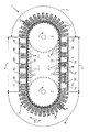
図1は、シート材料集まりを形成するための装置の概略的な平面図であり、シート材料積み体を収容するための定置の底なしのホッパと、可動なシート材料アセンブラとの関係を示している。
【0020】
統一された丁合い及び綴じ装置1は、互いに並んで配置されたシート材料アセンブラ12の無限チェーンを有しており、この無限チェーンは、2つの駆動輪2,3を取り囲むように循環させられる。定置のベース10上を移動させられる無限チェーンの上方には、複数の底なしのシート材料フィーダ9が配置されている。複数のシート材料フィーダ9a〜9jは、互いに間隔を置いて配置されている。
【0021】
巡回という言葉は、1つの所定のシート材料アセンブラ12が様々なシート材料フィーダ9全てに沿って1つの全体的な一巡を完了し、元の位置に戻ることを意味する。これに対してサイクルは、2つの隣接した供給部、例えば9b及び9cの間の連続的な軌道4の一部として規定される。
【0022】
シート材料アセンブラ12は、2つの線形区分5,6と第1の非線形区分7と第2の非線形区分8とによって規定された連続的な軌道4に沿って配置されている。図示したように前記連続的な軌道4に沿った方向14での搬送に基づき、前記シート材料アセンブラ12は、線形区分5において底なしのフィーダ9b〜9fを通過し、前記非線形区分7を通過した後、前記シート材料アセンブラ12は前記底なしのフィーダ9g〜9j及び9aを通過する。
【0023】
シート材料アセンブラ12は、シート材料アセンブラ12の巡回の間に、例えば、前記底なしのフィーダ9aからシート材料物品(折丁)17を受け取り、その後にアセンブラ12の回路の間に各フィーダ9からシート材料物品14を受け取る。複数のフィーダ9を通過する巡回の完了後には、シート材料アセンブラ12においてシート材料物品17の集まりが丁合いされている。
【0024】
各シート材料アセンブラ12は、ベルト13を駆動する、駆動軸11.1に取り付けられた駆動ローラ11を有している。前記ベルト13の個々の上側の軌道20は、米国特許第4988086号明細書に記載されているように前記底なしのフィーダ9の底部を形成している。前記複数の底なしのフィーダ9は、方形の側壁配列16から成っており、この側壁配列16内には、移動するシート材料アセンブラ12に供給したいシート材料17の積み体15が配置されている。
【0025】
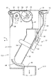
図2は、上側の区分と下側の区分とを有する1つのシート材料アセンブラの縦断面図であり、上側の区分は閉鎖した状態を占めている。
【0026】
各シート材料アセンブラ12は、上側のアセンブラ区分12.1と下側の綴じ区分12.2とを有している。上側のアセンブラ区分12.1は、1対の側部フレーム21を有しており、これらの側部フレーム21の間には前記ベルト13が取り付けられている。前記ベルト13は個々の上側の軌道20を有しており、この上側の軌道20は、側壁配列16の間に配置された積み体15からシート材料物品17を受け取る場合に、前記底なしのフィーダ9の個々の一時的な底部を形成している。ベルト13は、アイドラローラ22と、このアイドラローラ22とは異なる直径を有する別のアイドラローラ23とを取り囲むように循環する。前記ベルト13は、駆動軸11.1に取り付けられた前記駆動ローラ11(図1参照)によって駆動される。したがって、走行方向14でのシート材料アセンブラ12の移動に基づき、前記ベルト13は、図2に矢印19によって示したように反対方向に循環させられる。このように、前記上側のベルト軌道20は、前記底なしのフィーダ9の一時的な底部を形成する。軸25に取り付けられたグリッパヘッド26(概略的に図示)の作動に基づき、シート材料物品17は、真空ライン27によって供給されるグリッパヘッド26内の真空により掴まれ、右側の上側ポケット壁33と、前記シート材料アセンブラ12の前記側部フレーム21の間に配置された左側の上側ポケット壁34との間に送り込まれる。
【0027】
図2に示した位置においては、右側の上側ポケット壁33は閉鎖した状態を占めている。左側の上側ポケット壁34と右側の上側ポケット壁33との間の空間へのシート材料物品17の収容に基づき、シート材料物品の後縁が、公知の真空源に接続可能な吸引部材(図示せず)によって保持される。図2及び図3からさらに分かるように、前記右側の上側ポケット壁33は、この右側の上側ポケット壁33を個々の開放位置と閉鎖位置との間で移動させるために、第1の作動部材35と第2の作動部材36とから成るリンク装置に連結されている。
【0028】
個々の上側区分12.1は、さらに、ガイドプレート28を有しており、このガイドプレート28は、隣接するシート材料アセンブラ12と相俟って、上側のアセンブラ区分12.1へのホッパ状の挿入区分を形成している。さらに、前記真空ライン27内の真空のスイッチが切られた後に前記グリッパヘッド26からシート材料物品17を穏やかに分離させるために、ストリッパブレード29が前記ベルト13の下方に配置されている。
【0029】
シート材料アセンブラ12は、上側のアセンブラ区分12.1に対して横方向にずらされて配置された個々の下側の綴じ区分12.2を有している。前記上側のアセンブラ区分12.1は、傾斜した位置を占めるように方向付けられており、これに対して、下側の綴じ区分12.2は、矢印19によって示したベルトの走行方向に対して垂直に方向付けられている。右側の上側ポケット壁33は、カム装置を介して、又はニューマチック式手段によって解放位置43へ移動させられる(図4(d))。したがって、フィーダ9を通過するシート材料アセンブラ12の巡回に基づき前記左側の上側ポケット壁34と前記右側の上側のポケット壁33との間に丁合いされた前記丁合いされた集まりは、前記下側の綴じ区分12.2内へ移動させられるために、下側の綴じ区分の入口領域45(図4(a))に受け渡されることができる。前記下側の綴じ区分12.2の個々の鉛直の配向は、下側の綴じ区分12.2において、丁合された集まりに対して行いたい綴じ作業を助成する。
【0030】
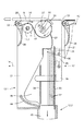
図3は、上側のアセンブラ区分12.1と下側の綴じ区分12.2とを有する1つのシート材料アセンブラの縦断面図である。上側のアセンブラ区分12.1は、丁合された集まりを下側の綴じ区分12.2へ受け渡すための受渡し位置を占めている。
【0031】
全巡回の完了に基づき、シート材料の集まり46(図4(a))は、左側の上側ポケット壁34と右側の上側ポケット壁33との間に丁合いされる。図3に示した段階においては、シート材料集まりは、上側アセンブリ区分ポケット12.1から出て、下側の綴じ区分12.2の入口領域45に進入する位置を占めている。
【0032】
図3に示したように、ポケット壁33,34は作動部材35,36の前記リンク装置37に結合されている。したがって、両ポケット壁33,34は解放位置へ移動させられる。同時に、様々なシート材料物品17が、完全な集まり46を形成しており、この集まり46は、重力によってシート材料アセンブラ12の個々の綴じ区分12.2へ移動させられる。
【0033】
丁合い及び綴じラインの前の巡回の間に丁合いされた集まり46が別の巡回において個々の下側の綴じ区分12.2へ受け渡された後、別の集まりが、左側の上側ポケット壁34と右側の上側ポケット壁33との間に丁合いされる。
【0034】
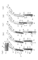
図4は、様々な段階におけるシート材料アセンブラを示す概略図であり、このシート材料アセンブラは、上側のアセンブラ区分と下側の綴じ区分とを有しており、この図4は、上側のアセンブラから下側の綴じ区分への第1の丁合いされた集まりの受渡しを示している。
【0035】
ベルト駆動部材、すなわちベルト13と、アイドラローラ22,23とが図4に概略的に示されている。
【0036】
1つのサイクルの間に1つの所定のシートアセンブラ12が占める種々異なる段階が、図4に示されている。シート材料物品17の積み体15は、フィーダ9における側壁配列16によって取り囲まれている。図4(a)に示した段階においては、シート材料物品17は、底なしのフィーダ9から、丁合いされた集まり46へ送られる。図4(a)に示したように、シート材料物品17は、集まり46を完成させるために、左側の上側ポケット壁34と右側の上側ポケット壁との間に保持された丁合いされた集まり46へ送られる。前記下側の綴じ区分12.2においては、集まり47は解放部材49によって支持されており、この解放部材49は軸49.1を中心にして旋回可能に取り付けられている。集まり47は、前記底なしのフィーダ9を通過するシート材料アセンブラ12の前の巡回の間に丁合いされている。
【0037】
図4(b)に示したように、同じシート材料アセンブラ2は連続的な軌道4に沿って移動させられており、集まり47は鉛直方向に方向付けられておりかつ今や綴じ処理に露出させられている。したがって、集まり47の背50は、解放部材9を旋回離反させることによって露出させられている。今や、背50に接着剤を塗布する前に、集まり47の背50を準備するために背50からの材料の取出しが行われ、この間集まり46は上側のアセンブリ区分12.1において保持されており、またシート材料が集まり46に供給されてよい。集まり47の背50からの材料の取出しの間、集まり47は側壁51,52の間に締め付けられている。材料は、切欠きをつける装置又は粗くする装置等の、公知の適切な工具によって背から取り出される。側壁52は、集まり47を締め付けるために側壁51に向かって可動である。接着剤が前記背50に塗布された後、カバーが集まり47に当て付けられ、接着剤によって背50に固定されることが考えられる。
【0038】
下側の綴じ区分12.2からの集まり47の取出し時には、上側のアセンブラ区分12.1内の集まり46は、図4(c)に示したように、右側の上側ポケット壁33によって所定の位置に保持される。
【0039】
集まり47は、側壁52を締付け位置から移動させることによって下側の綴じ区分12.2から取り出される。これにより、固定されたカバーを備えた集まりは、綴じ区分12.2から落下することができる。この後、必要であればカバーパネル(前及び後ろ)が集まりに対して折り畳まれてもよく、又は、カバーはこのように前もって折り畳まれていてもよい。今や集まり47は、集まり47を郵送順に他の集まりとひとまとめにするための状態を占めている。これらのひとまとまりは、種々異なる仕上げ裁ち及び郵送ラインへ引き渡される。付加的な仕上げ裁ちが必要ではない場合には、集まり47は適切な郵送ラインへ直接に引き渡されることができる。
【0040】
図4(c)に示した段階の後、解放部材49は図4(d)に示したように閉鎖される。したがって、閉鎖されたポケットが個々の側壁51,52と閉鎖された解放部材49との間に形成される。次いで、右側の上側ポケット壁33が解放位置へ移動させられ(図3及び図4(d)参照)、この右側の上側ポケット壁33は、右側の上側ポケット壁33と上側のアセンブラ区分の底部44とによって前もって保持されていた、丁合いされた集まり46を解放する。次いで丁合いされた集まり46は、重力によって下側の綴じ区分12.2へ落下する。
【0041】
右側の上側ポケット壁33が図4(e)に示したように元の位置へ戻り旋回させられた後、新たな集まりが、連続的な軌道4に沿ったシート材料アセンブラ12のその後の巡回の間に、上側のアセンブラ区分12.1に丁合いされることができる。図4(e)に示した段階においては、上側のアセンブラ区分12.1に新たなシート材料物品17を丁合いする間に、解放部材49が離れるように移動させられて鉛直に方向付けられた集まりの背50が露出させられた後に、綴じ作業が集まり46の底側縁部50に行われることができる。集まり46を締め付けるために、側壁52は側壁51に対して移動させられることができる。
【0042】
図示したように、本発明は種々異なる機械への集まり46,47への受渡しを排除する。受渡しは、シート材料アセンブラ12の上側区分と下側区分との間においてのみ行われ、受渡しは潜在的な紙詰まりを回避するような制御された形式で行うことができる。受渡しは、より多くのサイクルに亘って行うことができ、これにより受渡しは低速でかつ制御されているようにすることができる。下側の綴じ区分12.2において綴じ作業が集まりに対して行われている間に、新たな集まりが上側のアセンブラ区分12.1において丁合いされることができる。
【0043】
また、図4に示したように、上側のアセンブラ区分12.1の壁34は、図2及び図3に示したように、壁33と一緒に移動しないことは明らかである。このような場合には、壁33は上側のアセンブラ区分12.1において集まりを部分的に取り囲む手段を有していてよく、これにより、集まりを下側の綴じ区分12.2に受け渡すために壁33が移動する場合には、壁33は、丁合された集まりを壁33と一緒に連行する。さらに、図4に示したように、アイドラローラ22,23とベルト13とが、図2に示したのとは反対向きで示されている。図4には概略的にしか示されていない。
【0044】
また、図4(b)に示したように、側壁51,52は集まり47の底側縁部(背50)において終わっている。側壁51,52は、集まり47の一部がこれらの側壁51,52の下方へ突出するように背50よりも短く終わっているのが最も有利である。これにより、粗くする機構又は切欠きをつける機構を用いて、露出した背50に対して作業することがさらに容易となり、また、背50に接着剤及びカバーを供給することがさらに容易となる。
【図面の簡単な説明】
【図1】 シート材料集まりを形成するための装置を示す概略的な平面図である。
【図2】 閉鎖状態を占めた、上側の区分と下側の区分とを有する1つのシート材料アセンブラを示す縦断面図である。
【図3】 受渡し状態を占めた、上側の区分と下側の区分とを有する1つのシート材料アセンブラを示す縦断面図である。
【図4】 上側の区分から下側の区分への丁合された集まりの受渡しを示す、様々なシート材料アセンブラの状態の概略図である。
【符号の説明】
1 統一された丁合い及び綴じ装置、 2,3 駆動ローラ、 4 連続的な軌道、 5,6 線形の区分、 7,8 非線形の区分、 9 フィーダ、 10 ベース、 12 シート材料アセンブラ、 12.1 上側のアセンブラ区分、 12.2 下側の綴じ区分、 13 ベルト、 14 走行方向、 15 積み体、 16 側壁配列、 17 シート材料、 20 上部走行部、 21 側部フレーム、 22,23 アイドラローラ、 25 軸、 26 グリッパヘッド、 27 真空ライン、 33,34 上側ポケット壁、 35,36 作動部材、 43 解放位置、 45 入口領域、 46,47 集まり、 49 解放部材、 50 背、 51,52 側壁[0001]
BACKGROUND OF THE INVENTION
The present invention relates to an apparatus and method for unified collating and binding of sheet-like articles on the same production line.
[0002]
[Prior art]
U.S. Pat. No. 3,580,563 relates to a collator that feeds into or out of a rack. The horizontal framework supports a plurality of lateral, inclined, parallel, paper support racks. A conveying system provided in the collating machine having a belt conveys a sheet of paper coming out of the reproducing apparatus to a predetermined one rack. After the desired number of sheets are placed in the rack in the proper order, various adjustments are made to the collator, including reversing the belt movement, so that the collator is pre-collected in the rack. A paper sheet can be collated. The collating mechanism has a structure that allows the driver to adapt the collating machine to the changing paper size, pattern and weight.
[0003]
U.S. Pat. No. 5,251,888 relates to an insertion machine with a pocket having an adjustable stop. Each pocket arranged at regular intervals and movable along an endless track is provided with two vertically adjustable stoppers for the substrate to be placed in this pocket. . The stopper is movably attached to the pocket support device. A slide member is disposed horizontally in the pocket carrier and has two elongated openings that are slightly inclined with respect to the horizontal direction. The protrusion provided on each stopper is guided in a corresponding opening of the slide member, that is, causes the stopper to move in the vertical direction. The guide member which is movable in the direction of the slide member provided on the carrier fixed to the machine has a groove for a projection arranged at the protruding end of the slide member. Based on the passage of the pocket, the protrusion moves through the guide groove so that the slide is positioned at the corresponding horizontal position and the stopper is positioned at the corresponding vertical position. Therefore, only the guide member needs to be newly set on the carrier in order to position the substrate at the correct height in all the pockets based on the change in the height of the substrate.
[0004]
U.S. Pat. No. 4,133,521 relates to a sheet material collating apparatus. In a newspaper stuffing device, the pockets that serve to contain the newspaper jacket and the inner part pass along a track of the first feeder containing the openable jacket along an endless track and within the open jacket in the continuous pocket. Is passed through a discharge device which passes through at least one second feeder which puts the inner part into the magazine and takes out the newspaper thus collated from a continuous pocket. Each pocket is associated with a holding blade that is held at one end as it travels through the first feeder, and this holding blade is moved into the pocket by a spring toward the second feeder. And during travel through the second feeder, the open jacket half is clamped against one wall of the pocket and retracted from the pocket as soon as the pocket reaches the discharge device. Each blade is reciprocally movable along the guide shaft and is held non-rotatable with respect to the guide shaft, and the guide shaft is disposed behind one wall of each pocket, And can be rotated to move the blade away from or away from the open jacket half.
[0005]
Finally, US Pat. No. 4,988,086 describes sheet material gathering The present invention relates to an apparatus and a method for forming a film. Sheet material gathering The apparatus for forming the sheet material has a plurality of sheet material assemblers that run on a continuous track and run continuously under the sheet material stack. The sheet material stack is placed in a bottomless hopper. The sheet material assembly has a belt that supports the sheet material stack in a bottomless hopper. The belt moves with the sheet material assembler to continuously engage the stack of sheet material. Since the upper track of the belt moves in the opposite direction to the sheet material assembler, the upper track of the belt is stationary with respect to the material stack. The sheet material assembler has a feeding mechanism and a storage position. While the sheet material assembler passes under the sheet material stack, the sheet material is fed from the sheet material stack to the receiving position by the feeding mechanism.
[0006]
Based on collating signatures of bound products, the most common disadvantage is that it is difficult to deliver and redirect products for binding. In the case of a continuously arranged assembly of processing components used today to produce books and periodicals, product delivery often takes place in the process, each of these delivery being a paper jam and other There is a risk of negative situations.
[0007]
[Problems to be solved by the invention]
That is, in the case of the prior art solutions that are known in the art and that indicate technical problems, one main object of the present invention is to perform the binding process without having to deliver the product to another machine. Collage with necessary components apparatus Is to provide.
[0008]
Another object of the present invention is to reduce the size and cost of the machine used.
[0009]
Yet another object of the present invention is to process the product in a direction perpendicular to the surface direction at the short center in order to reduce the processing speed.
[0010]
[Means for Solving the Problems]
In order to solve this problem, in the configuration of the present invention, a plurality of sheet material feeders arranged along a continuous track, and along the continuous track for receiving sheet material articles from the sheet material feeder. A plurality of continuously movable sheet material assemblers are provided, and this sheet material assembler gathering A sheet material collated from a first section for collating the sheet material article formed with the first assembler section gathering A second binding section for receiving gathering The binding operation is performed in the second binding section.
[0011]
Moreover, according to the method of the present invention, the sheet material article is collated in the first section of the sheet material assembler, and the sheet material article gathering Is passed to the second binding section of the sheet material assembler, and in this second binding section gathering Tighten the above gathering Remove the material from the bottom edge of the individual sheet material article, apply the adhesive to the exposed edge surface of the sheet material article, apply the cover to the adhesive to surround the sheet material article, and be bound The product consists of finishing trimming and / or delivering to the mailing line.
[0012]
【The invention's effect】
Certain solutions according to the invention eliminate frequent delivery of products. This individual delivery can cause a paper jam or failure. No longer collated to perform binding gathering There is no need to pass the to another machine. According to the present invention, the binding line is successfully incorporated into the collating line, thereby gathering Significantly reduces the risk of exposure to paper jams. In addition, the sheet material articles are oriented vertically toward the stack position and are individually gathering Is arranged at a position for assisting the binding operation.
[0013]
According to the invention, the upper section and the lower binding section have a sheet material delivery area. The bottom of the upper assembler section is offset laterally from the entry area of the lower binding section. The individual lower binding sections are oriented vertically towards the position of the stack of sheet material articles. This orientation was collated passed to the lower binding section gathering The binding work in the process is remarkably facilitated. Collated gathering The upper assembler section has a movable pocket wall member so as to pass it reliably towards the lower binding section. The movable wall member is coupled to a link device, which is cam actuated or pneumatic actuated and collated gathering Can be pivoted to a release position that connects the bottom of the upper assembler section to the entry area of the lower binding section. The lower binding section is provided with a release member, which is pivotally attached to the shaft and received. gathering The back of the can be exposed in preparation for the binding operation. Collated gathering With a nearly vertical orientation of gathering Is now exposed and can be bound to this edge. In contrast, based on the completion of another tour along the sheet material article feeder, the individual upper assembler section of the sheet material assembler is replaced with a new sheet material. gathering Was collated before, during this time gathering Are bound in the individual lower binding sections.
[0014]
A method for collating and binding sheet material articles in a sheet material assembler according to the present invention involves collating the sheet material article with the upper section of the sheet material assembler, gathering To the lower section of the sheet material assembler, gathering Tighten the above gathering Remove material from the bottom edge of each individual sheet, apply adhesive to the surface of the bottom edge, gathering A cover for enveloping the adhesive and the steps of delivering the bound product to a number of different finishing cuts and / or mailing lines.
[0015]
In order to deliver the collated sheet material article in the upper section of the sheet material assembler, the sheet material article is moved laterally by the pocket wall. Collated based on the lateral movement of the collated sheet material article collated in the upper assembler section gathering Is released towards the lower binding section. Individual sheet materials that are collated in the upper assembler section and bound in the lower binding section gathering Is held in a substantially vertical direction to facilitate the binding operation. Sheet material received from upper assembler section gathering Is gathering In order to facilitate the removal of the material from the bottom edge (back), it is clamped in the lower binding section. The removal of this material gathering To facilitate the application of the adhesive to individual sheets. Collated gathering After applying adhesive to the back consisting of the exposed bottom edge of the gathering It is applied to.
[0016]
During a first round along a continuous trajectory, a sheet material assembler having an upper assembler section and a lower binding section collates all of the sheet material from the supply in each upper assembler section. . After the first patrol along the supply section is completed, the collated gathering Is passed to the lower binding section of the individual sheet material assembler. Collated from individual upper section of sheet material assembler to individual lower section gathering Delivery may occur during multiple cycles of the sheet material assembler along a continuous trajectory. New sheet material based on another cycle of sheet material assembler along a continuous trajectory gathering Was collated in the upper assembler section, during which time it was collated in the previous circuit gathering Are bound in the lower binding section.
[0017]
DETAILED DESCRIPTION OF THE INVENTION
In the following, embodiments of the present invention will be described in detail with reference to the drawings.
[0018]
The novel features believed characteristic of the invention are set forth with particularity in the appended claims. However, the present invention itself can be understood from the following description of specific embodiments when read with reference to the drawings, with regard to configurations and operating methods with additional objects and advantages.
[0019]
Figure 1 shows the sheet material gathering FIG. 2 is a schematic plan view of an apparatus for forming a sheet, showing the relationship between a stationary bottomless hopper for receiving sheet material stacks and a movable sheet material assembler.
[0020]
Unified collation and binding apparatus 1 has an infinite chain of
[0021]
The term tour means that one given
[0022]
The
[0023]
The
[0024]
Each
[0025]
FIG. 2 is a longitudinal cross-sectional view of one sheet material assembler having an upper section and a lower section, with the upper section occupying a closed state.
[0026]
Each
[0027]
In the position shown in FIG. 2, the right
[0028]
Each upper section 12.1 further comprises a
[0029]
The
[0030]
FIG. 3 is a longitudinal section view of one sheet material assembler having an upper assembler section 12.1 and a lower binding section 12.2. Upper assembler section 12.1 collated gathering Occupies a delivery position for delivering to the lower binding section 12.2.
[0031]
Based on the completion of the entire tour, gathering 46 (FIG. 4A) is collated between the left
[0032]
As shown in FIG. 3, the
[0033]
Collated during the patrol before the collating & binding line gathering After 46 is passed to each lower binding section 12.2 in another tour, gathering Between the left
[0034]
FIG. 4 is a schematic diagram showing the sheet material assembler at various stages, the sheet material assembler having an upper assembler section and a lower binding section. 1st collated to lower binding section gathering Indicates delivery.
[0035]
The belt drive member, i.e., the
[0036]
The different stages occupied by a given
[0037]
As shown in FIG. 4 (b), the same sheet material assembler 2 is moved along a
[0038]
From lower binding section 12.2. gathering When 47 is removed, the upper assembler section 12.1 gathering As shown in FIG. 4C, 46 is held at a predetermined position by the
[0039]
gathering 47 is removed from the lower binding section 12.2 by moving the
[0040]
After the step shown in FIG. 4 (c), the
[0041]
After the right
[0042]
As shown, the present invention can be applied to different machines. gathering Delivery to 46 and 47 is excluded. Delivery takes place only between the upper and lower sections of the
[0043]
Also, as shown in FIG. 4, it is clear that the
[0044]
Further, as shown in FIG. 4B, the
[Brief description of the drawings]
[Figure 1] Sheet material gathering It is a schematic plan view which shows the apparatus for forming.
FIG. 2 is a longitudinal cross-sectional view of one sheet material assembler having an upper section and a lower section that occupy a closed state.
FIG. 3 is a longitudinal cross-sectional view of one sheet material assembler having an upper section and a lower section that occupy a delivery state.
FIG. 4 Collated from upper section to lower section gathering FIG. 2 is a schematic view of various sheet material assembler states showing delivery of the sheet;
[Explanation of symbols]
1 Unified collation and binding apparatus , 2,3 Drive roller, 4 Continuous trajectory, 5,6 Linear section, 7,8 Non-linear section, 9 Feeder, 10 Base, 12 Sheet material assembler, 12.1 Upper assembler section, 12.2 Bottom Side binding section, 13 belt, 14 running direction, 15 stack, 16 side wall arrangement, 17 sheet material, 20 upper running section, 21 side frame, 22, 23 idler roller, 25 shaft, 26 gripper head, 27
Claims (19)
連続的な軌道(4)に沿って配置された複数のシート材料フィーダ(9)と、
該シート材料フィーダ(9)からシート材料物品を受け取るために前記連続的な軌道(4)に沿って連続的に可動な複数のシート材料アセンブラ(12)とが設けられており、
該シート材料アセンブラ(12)が、集まり(46)を形成したシート材料物品(17)を丁合いするための第1のアセンブラ区分(12.1)と該第1のアセンブラ区分(12.1)から丁合いされたシート材料集まり(46)を受け取るための第2の綴じ区分(12.2)とを有しており、前記集まり(46)に対する綴じ作業が第2の綴じ区分(12.2)において行われるようになっていることを特徴とする、シート状物品の統一された丁合い及び綴じのための装置。A sheet material collating and binding device comprising :
A plurality of sheet material feeders (9) arranged along a continuous track (4);
A plurality of sheet material assemblers (12) continuously movable along said continuous track (4) for receiving sheet material articles from said sheet material feeder (9);
A first assembler section (12.1) and a first assembler section (12.1) for the sheet material assembler (12) to collate the sheet material article (17) forming the mass (46); collated second binding section for receiving the sheet material collection (46) (12.2) has a, stitching work for the collection (46) of the second binding section from (12.2 A device for uniform collation and binding of sheet-like articles, characterized in that
連続的な軌道に沿って連続的に可動な複数のシート材料アセンブラ(12)のうちの第1のシート材料アセンブラ(12)の第1のアセンブラ区分(12.1)においてシート材料物品(17)を丁合いし、
シート材料物品(17)の集まりをシート材料アセンブラ(12)の第2の綴じ区分(12.2)へ受け渡し、
該第2の綴じ区分(12.2)においてシート材料集まり(47)を締付け、
前記シート材料集まり(47)の個々のシート材料物品の底側縁部から材料を取り出し、
シート材料物品の露出した縁部の表面に接着剤を塗布し、
シート材料物品を取り囲むように接着剤にカバーを当て付け、
綴じられた製品を仕上げ裁ち及び/又は郵送ラインへ引き渡す
ステップから成ることを特徴とする、シート状物品の統一された丁合い及び綴じのための方法。A method for collating and binding sheet material articles in a sheet material assembler comprising:
Sheet material article (17) in a first assembler section (12.1) of a first sheet material assembler (12) of a plurality of sheet material assemblers (12) continuously movable along a continuous trajectory Collate
Passing the collection of sheet material articles (17) to the second binding section (12.2) of the sheet material assembler (12);
Tightening the sheet material mass (47) in the second binding section (12.2) ;
Removing material from the bottom edge of individual sheet material articles of the sheet material mass (47);
Apply adhesive to the exposed edge surface of the sheet material article,
Apply a cover to the adhesive to surround the sheet material article,
A method for unified collating and binding of sheet-like articles, comprising the step of delivering the bound product to a finishing cut and / or a mailing line.
Applications Claiming Priority (2)
| Application Number | Priority Date | Filing Date | Title |
|---|---|---|---|
| US08/946,516 US5921538A (en) | 1997-10-07 | 1997-10-07 | Apparatus and method for combined gathering and binding of sheet like articles |
| US08/946516 | 1997-10-07 |
Publications (2)
| Publication Number | Publication Date |
|---|---|
| JPH11189366A JPH11189366A (en) | 1999-07-13 |
| JP4046868B2 true JP4046868B2 (en) | 2008-02-13 |
Family
ID=25484592
Family Applications (1)
| Application Number | Title | Priority Date | Filing Date |
|---|---|---|---|
| JP28404298A Expired - Fee Related JP4046868B2 (en) | 1997-10-07 | 1998-10-06 | Apparatus and method for unified collation and binding of sheet-like articles |
Country Status (5)
| Country | Link |
|---|---|
| US (1) | US5921538A (en) |
| EP (1) | EP0908408B1 (en) |
| JP (1) | JP4046868B2 (en) |
| CN (1) | CN1093496C (en) |
| DE (2) | DE19839312A1 (en) |
Families Citing this family (20)
| Publication number | Priority date | Publication date | Assignee | Title |
|---|---|---|---|---|
| ES2158662T3 (en) * | 1997-02-14 | 2001-09-01 | Ferag Ag | DEVICE FOR PRODUCING PRINTED MATERIALS OF VARIOUS PARTS. |
| JP3648073B2 (en) * | 1998-05-29 | 2005-05-18 | シャープ株式会社 | Sheet post-processing device |
| US6213457B1 (en) * | 1998-12-29 | 2001-04-10 | Heidelberger Druckmaschinen | Apparatus and method for feeding sheet material magazines |
| US6267366B1 (en) | 1999-10-25 | 2001-07-31 | Quad/Graphics, Inc. | Apparatus and method of delivering signatures to a binding line |
| US6447229B1 (en) * | 2000-05-12 | 2002-09-10 | Heidelberger Druckmaschinen Ag | Device and method for preparing a book spine for binding |
| US6547501B2 (en) * | 2001-03-22 | 2003-04-15 | Heidelberger Druckmaschinen Ag | Device and method for binding printed products |
| DE50204002D1 (en) * | 2001-04-26 | 2005-09-29 | Ferag Ag | Apparatus for gathering flat objects into stacks and for further processing the stacks |
| JP3721131B2 (en) * | 2002-01-28 | 2005-11-30 | 日本電気株式会社 | Transport mechanism |
| US6695306B2 (en) * | 2002-06-24 | 2004-02-24 | Heidelberger Druckmaschinen Ag | Sheet material conveying apparatus with height-adjustable pockets |
| DE10303979B3 (en) * | 2003-01-31 | 2004-07-08 | Siemens Ag | Letter stack compartment for mail sorting machine with driven displacement device infront of stacking point for rapid emptying of stack compartment |
| DE102004021958A1 (en) * | 2004-05-04 | 2005-12-01 | Heidelberger Druckmaschinen Ag | Saddle stitcher for brochures |
| US7325375B2 (en) * | 2004-06-23 | 2008-02-05 | Quad/Graphics, Inc. | Selective product inserter apparatus and process |
| GB0420036D0 (en) * | 2004-09-09 | 2004-10-13 | Pitney Bowes Ltd | Accumulator for sheet handling apparatus |
| US7571902B2 (en) * | 2004-11-17 | 2009-08-11 | Goss International Americas, Inc. | Sheet material conveying apparatus with dual-bottom pockets |
| US7611135B2 (en) * | 2005-12-05 | 2009-11-03 | Goss International Americas, Inc. | Inserter with closure device |
| EP2280892A4 (en) * | 2008-05-20 | 2012-11-07 | Goss Int Americas Inc | DEVICE AND METHOD FOR MULTIPLEX ASSEMBLY |
| US20120170996A1 (en) * | 2010-12-01 | 2012-07-05 | Michael Speller | Adhesive application module for a batcher unit in a book block finishing machine |
| CN103662957A (en) * | 2012-09-15 | 2014-03-26 | 张洪彬 | Origami method and device for producing filter elements |
| DE102013017223A1 (en) * | 2013-10-17 | 2015-04-23 | Manroland Web Systems Gmbh | Device for forming book blocks |
| DE102022117920A1 (en) * | 2022-07-18 | 2024-01-18 | Müller Martini Holding AG | Device for producing an adhesive-bound printed product with a transport system |
Family Cites Families (11)
| Publication number | Priority date | Publication date | Assignee | Title |
|---|---|---|---|---|
| CH411779A (en) * | 1963-05-17 | 1966-04-30 | Mueller Hans Grapha Masch | Conveyor chain for stacks of sheets of paper, sheets and books |
| US3580563A (en) * | 1969-01-30 | 1971-05-25 | Ernest D Bassett | Collating machine feeding into or out of racks |
| CH594552A5 (en) * | 1976-02-19 | 1978-01-13 | Grapha Holding Ag | |
| US4477067A (en) * | 1982-05-10 | 1984-10-16 | Harris Graphics Corporation | Method and apparatus for assembling sheet material assemblages |
| US4721296A (en) * | 1986-05-27 | 1988-01-26 | Harris Graphics Corporation | Sheet material handling apparatus |
| DE3805877A1 (en) * | 1988-02-25 | 1989-08-31 | Roland Man Druckmasch | ADDRESSING DEVICE FOR PRODUCTS, ESPECIALLY FOR FOLDING PRODUCTS |
| FR2628685B1 (en) * | 1988-03-21 | 1990-08-24 | Ordibel | MACHINE FOR BINDING SHEETS OF PINK SHEETS |
| US4988086A (en) * | 1989-01-26 | 1991-01-29 | Am International Incorporated | Apparatus and method for forming sheet material assemblages |
| CA2010094A1 (en) * | 1989-03-09 | 1990-09-09 | Robert R. Butler | Binding line book tracking system and method |
| CH681448A5 (en) * | 1990-09-12 | 1993-03-31 | Grapha Holding Ag | |
| US5186443A (en) * | 1991-02-28 | 1993-02-16 | Am International Incorporated | Method of collating newspapers based upon credit card holders |
-
1997
- 1997-10-07 US US08/946,516 patent/US5921538A/en not_active Expired - Lifetime
-
1998
- 1998-08-28 DE DE19839312A patent/DE19839312A1/en not_active Withdrawn
- 1998-08-28 EP EP98116310A patent/EP0908408B1/en not_active Expired - Lifetime
- 1998-08-28 DE DE59806171T patent/DE59806171D1/en not_active Expired - Lifetime
- 1998-09-28 CN CN98120057A patent/CN1093496C/en not_active Expired - Fee Related
- 1998-10-06 JP JP28404298A patent/JP4046868B2/en not_active Expired - Fee Related
Also Published As
| Publication number | Publication date |
|---|---|
| EP0908408A2 (en) | 1999-04-14 |
| EP0908408A3 (en) | 2000-01-05 |
| EP0908408B1 (en) | 2002-11-06 |
| JPH11189366A (en) | 1999-07-13 |
| HK1018608A1 (en) | 1999-12-30 |
| CN1213640A (en) | 1999-04-14 |
| DE19839312A1 (en) | 1999-04-08 |
| US5921538A (en) | 1999-07-13 |
| CN1093496C (en) | 2002-10-30 |
| DE59806171D1 (en) | 2002-12-12 |
Similar Documents
| Publication | Publication Date | Title |
|---|---|---|
| JP4046868B2 (en) | Apparatus and method for unified collation and binding of sheet-like articles | |
| US3995748A (en) | Sorter apparatus | |
| CA1264167A (en) | Method and apparatus for opening printed products which have been folded off-center | |
| US4533132A (en) | Collating machine | |
| US4575296A (en) | Apparatus and method for preparing multipage, side-stitched documents | |
| JPH07266736A (en) | Device for binding printed materials and binding | |
| JPH0233058A (en) | Device for conducting collection and insertion of print | |
| US3658318A (en) | Method and apparatus for adding loose inserts to magazines | |
| JPH0280296A (en) | Device and method for discretely printing signature during time when signature is fed to bookbinding line conveyor | |
| JP2001287829A (en) | Graphic publication rotating device for conveyor line and/or packaging machine | |
| US4456242A (en) | Apparatus for shingling stack of flat articles | |
| US2845264A (en) | Signature feeding and opening mechanism | |
| US4200275A (en) | Collating machine | |
| US4083551A (en) | Method and apparatus for on-line tipping of inserts | |
| JP2708422B2 (en) | Folding and conveying device | |
| US5727781A (en) | Process and apparatus for combining printed products | |
| CA2146808C (en) | Apparatus for processing printed products | |
| US6270068B1 (en) | Transport device | |
| US6581753B1 (en) | Transport apparatus | |
| US8096542B2 (en) | Method and arrangement for producing perfect bound book blocks | |
| US7572090B2 (en) | Method for producing a printed end product comprised of one or more printed products and device for performing the method | |
| US3431805A (en) | Magazine counting and destroying apparatus | |
| JPH10338402A (en) | Device for decelerating sheet material while maintaining sheet register | |
| JP2993552B2 (en) | Autoloader for bookbinding | |
| HK1018608B (en) | Apparatus and method for combined gathering and binding of sheet like articles |
Legal Events
| Date | Code | Title | Description |
|---|---|---|---|
| A621 | Written request for application examination |
Free format text: JAPANESE INTERMEDIATE CODE: A621 Effective date: 20050823 |
|
| A711 | Notification of change in applicant |
Free format text: JAPANESE INTERMEDIATE CODE: A711 Effective date: 20050902 |
|
| A711 | Notification of change in applicant |
Free format text: JAPANESE INTERMEDIATE CODE: A711 Effective date: 20060224 |
|
| A977 | Report on retrieval |
Free format text: JAPANESE INTERMEDIATE CODE: A971007 Effective date: 20070713 |
|
| A131 | Notification of reasons for refusal |
Free format text: JAPANESE INTERMEDIATE CODE: A131 Effective date: 20070718 |
|
| A521 | Request for written amendment filed |
Free format text: JAPANESE INTERMEDIATE CODE: A523 Effective date: 20071017 |
|
| TRDD | Decision of grant or rejection written | ||
| A01 | Written decision to grant a patent or to grant a registration (utility model) |
Free format text: JAPANESE INTERMEDIATE CODE: A01 Effective date: 20071109 |
|
| A61 | First payment of annual fees (during grant procedure) |
Free format text: JAPANESE INTERMEDIATE CODE: A61 Effective date: 20071121 |
|
| FPAY | Renewal fee payment (event date is renewal date of database) |
Free format text: PAYMENT UNTIL: 20101130 Year of fee payment: 3 |
|
| R150 | Certificate of patent or registration of utility model |
Free format text: JAPANESE INTERMEDIATE CODE: R150 |
|
| LAPS | Cancellation because of no payment of annual fees |